

Page 1
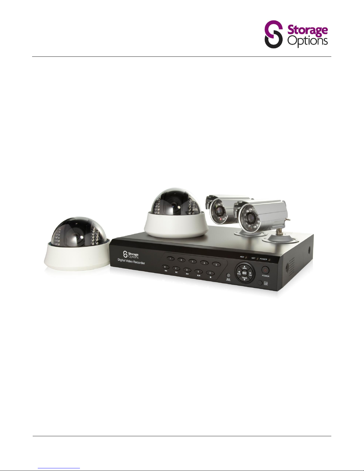
CCTV SECURITY SYSTEM
INSTRUCTION MANUAL
For the latest, up-to-date manual, please visit www.storageoptions.com
Page 2
Page 2
IMPORTANT SAFEGUARD
All lead-free products offered by the company comply with the requirements of the
European law of the Restriction of Hazardous Substances (RoHS) directive, which means our
manufacturing processes and products are strictly “lead-free” and without the hazardous
substances cited in the directive.
The crossed-out wheeled bin mark symbolizes that within the European Union the product
must be collected separately at the product’s end-of-life. This applies to your product and
any peripherals marked with this symbol. Do not dispose of these products as unsorted
municipal waste. Contact your local dealer for procedures for recycling this equipment.
DISCLAIMER
We reserve the right to revise or remove any content in this manual at any time. We do not warrant or assume any
legal liability or responsibility for the accuracy, completeness, or usefulness of this manual. The content of this
manual is subject to change without notice.
RECOMMENDATIONS
AVOID DUSTY LOCATIONS:
Excessive build-up of dust may cause the unit to fail.
INSTALL IN VENTILATED SPACE:
Ensure adequate airflow around the DVR to prevent overheating.
DO NOT EXPOSE TO MOISTURE:
Exposing the unit to water poses high risk of electric shock.
DO NOT DROP:
Doing so could damage internal components.
DO NOT OPEN CHASSIS:
No user-serviceable parts inside.
TRADEMARK ACKNOWLEDGEMENTS
Internet Explorer, Microsoft & Windows are registered trademarks of Microsoft Corporation.
DEFAULT PASS CODE INFORMATION
ADMIN ACCOUNT:
88888888
USER ACCOUNTS:
66666666
WARRANTY AND TECHNICAL SUPPORT
In the event that you need further assistance with this product you can call us, at local UK rate on the number below and our
UK-based experts will be happy to help you (they’re available Mon-Fri 9am – 5.30pm, excluding bank holidays). Alternatively
visit our website at www.storageoptions.com/support or send us an email at the address below.
UK:
Ireland:
0844 248 7191
00353 (0) 94 937 4026
Page 3

Page 3
TABLE OF CONTENTS
OVERVIEW
4
PACKAGE CONTENTS
6
INSTALLATION
7
3.1 – Mounting Cameras
3.2 – Connecting Cameras to the DVR
3.3 – Connecting the DVR to a Monitor
3.4 – Connecting the DVR to the Mains Supply
7
9
9
10
BASIC OPERATION
11
4.1 – Power On / Off
4.2 – Format the Hard Disk Drive
4.3 – Start / Stop Continuous Recording
4.4 – Playback
4.5 – Using the Mouse
4.6 – Remote Control Functions
11
11
11
12
12
13
MENU FUNCTIONS
14
5.1 – Accessing the Menu
5.2 – Basic
5.3 – Live
5.4 – Record
5.5 – Network
5.6 – Alarm Set
5.7 – Exception
5.8 – PTZ
5.9 – Preview
5.10 – User
5.11 – Backup
5.12 – Tools
14
15
16
17
18
19
19
20
20
21
22
23
NETWORK FUNCTIONS
24
6.1 – Connecting the DVR to a Network
6.2 – View and Record Live Cameras
6.3 – Playback of Recordings on the DVR
6.4 – Viewing Logs
6.5 – Remote DVR Configuration
24
25
26
27
28
USING ZMEYE FOR ANDROID
31
TROUBLESHOOTING
32
APPENDIX - PRODUCT SPECIFICATIONS
33
Page 4
Page 4
OVERVIEW
Key Features
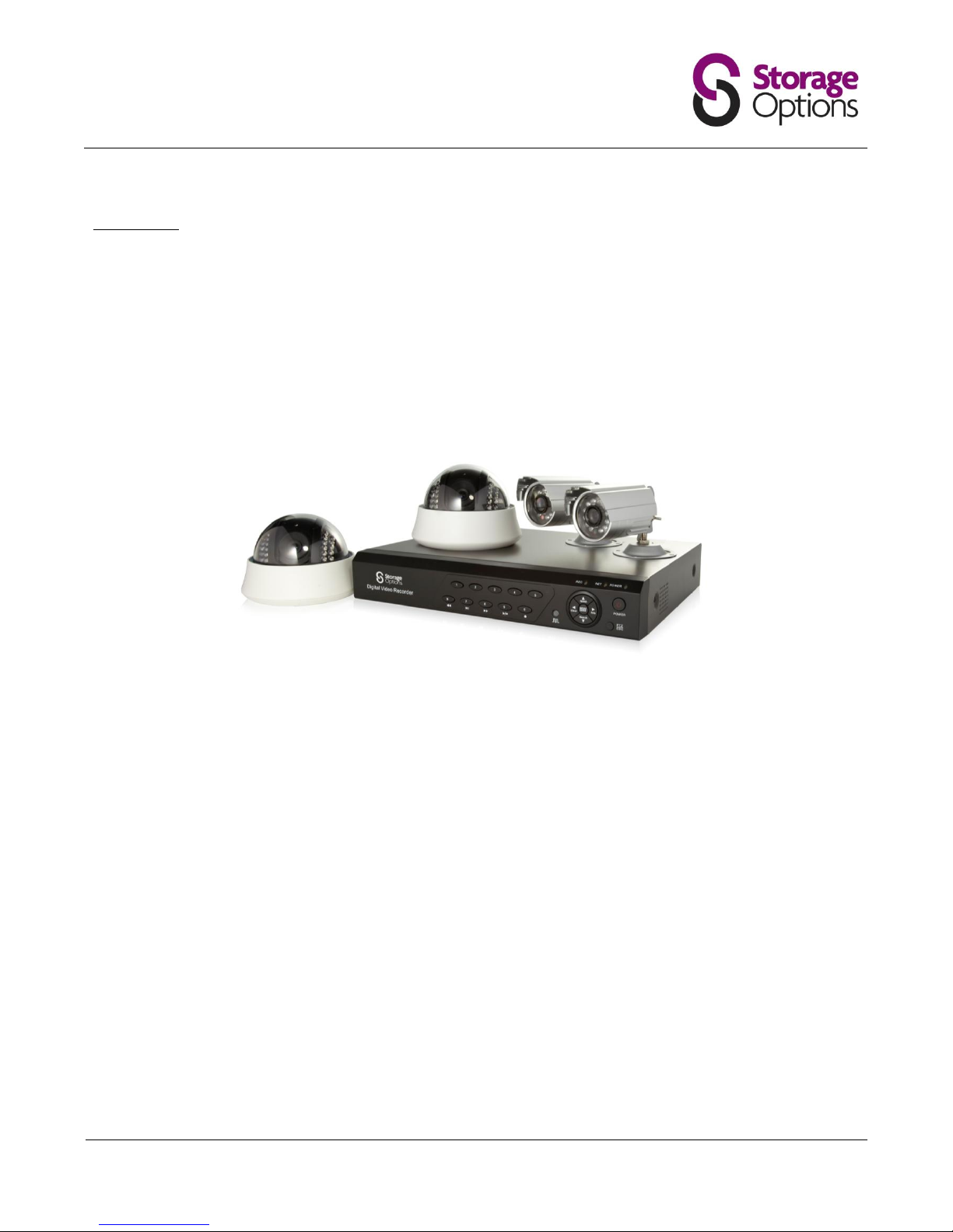
Storage Options presents a complete CCTV solution for home or office security, featuring up to four high-quality
cameras, internal HDD, easy setup and configuration, alarm triggers, and network connectivity.
Stand-alone DVR with H.264 compression
High quality video recording and playback
Supports real-time viewing and recording
Multiple recording / search categories
Date/Time, Event, Manual, Schedule, Alarm, Motion detection
Live view, record, playback, backup and network functions at the same time
Optimised Compression
H.264 compression algorithm provides higher definition and lower bandwidth requirements
Independent channel design – static (CBR) and dynamic (VBR) bit streams are available
Live Configuration
Compound video input, built-in anti-lightning protection
BNC and VGA simultaneous output
Real-time viewing of video feeds with no delay
Adjustment for contrast, brightness, hue and sharpness
Video Recording
Adjustable frame rate (0.1 – 25fps)
Multiple recording methods: manual / schedule / alarm / motion detect
Customisable bitrate and five preset quality levels
Motion Detection Function
48 motion detection areas can be set in each image
7 levels of sensitivity for each image
Page 5

Page 5
Search and Playback
Search by date / time or list
Normal / alarm-triggered search
4 Channel Playback
Synchronised playback of 2 channel or 4 channel AV
Transport: Fast forward, fast rewind, pause, single frame, previous track, next track, track head, track end
Alarm Function
Alarm input / output with triggering point
Upload alarm manually or by remote control / network
Remote Control Function
Supports 10/100 Mbps self-adaptive network
Supports remote setup of time (NTP)
Web-based interface compatible with Internet Explorer
Safety Protection
Dual password protection: administrator and operator
Power switch lock and front panel lock
Backup
Backup to external USB device according to time period
Backup to USB flash drive or external HDD
Page 6
Page 6
PACKAGE CONTENTS
Digital Video Recorder
DVR
Mains adapter
Mains splitter cable
Remote control
Mouse
2x AAA batteries
Cables
Manual
Outdoor Camera
Camera
Video / power combo cable
Mounting kit (screws & plugs)
Wall bracket
Dome Camera
Camera
Video / power combo cable
Mounting kit (screws & plugs)
Page 7
Page 7
INSTALLATION
3.1 – Mounting Cameras
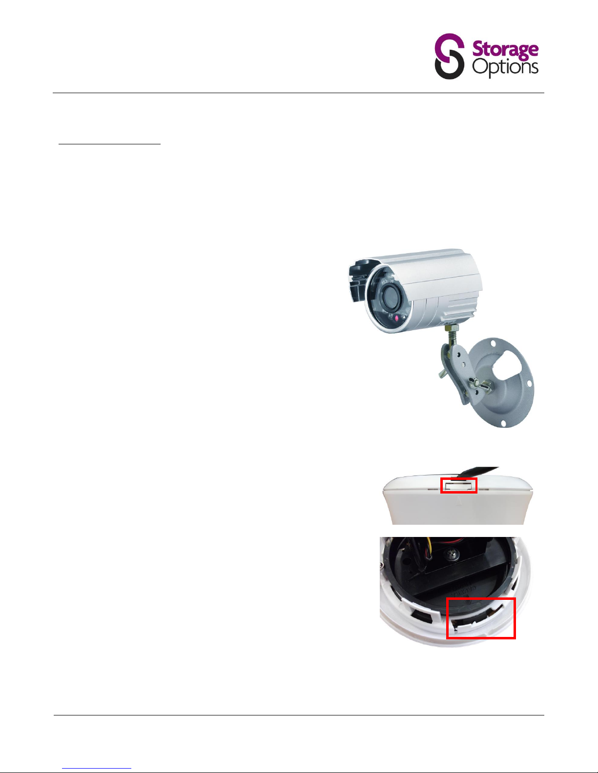
The cameras are supplied with mounting kits for attaching to a wall. Before you affix the cameras in position, please
ensure the cable is of adequate length to reach the DVR.
To mount each camera on a wall or ceiling, follow these instructions:
Outdoor Camera
1. Ensure the surface you want to mount the cameras on is solid
and can support the weight.
2. Accurately mark on the wall the position of the holes to be
drilled.
3. Drill to the correct depth in the wall, as indicated by the plugs.
4. Insert plugs into the drilled holes.
5. Secure the bracket to the wall using the provided screws.
Dome Camera
Locate the unlock catch on the top edge of the chassis and press it to
release the dome. Gently pull the units apart.
To unlock the mounting plate, locate the locking mechanism and pull it
towards the outer edge of the chassis.
Page 8
Page 8
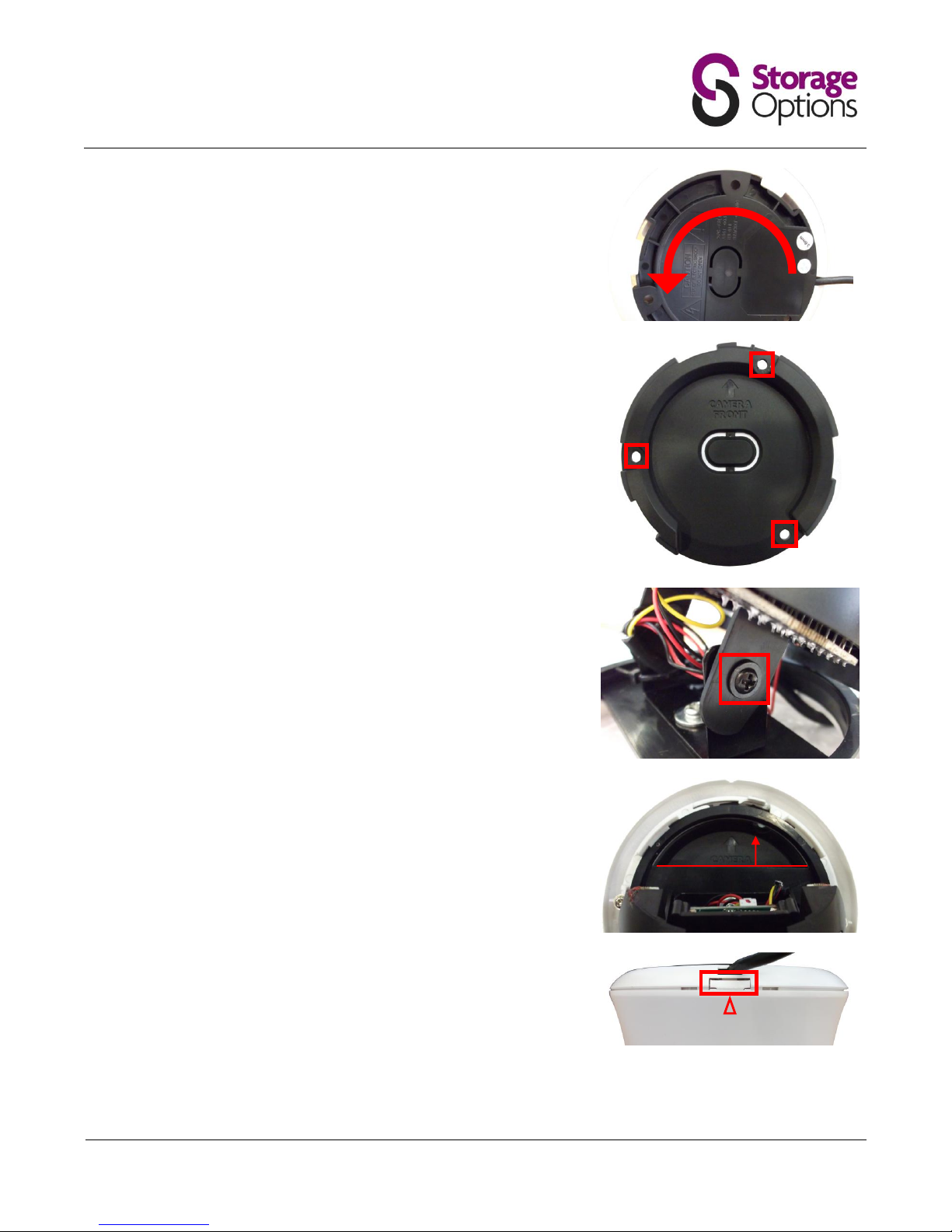
While holding the locking mechanism in the unlocked position, flip the
camera over and twist the ceiling mount unit (large black plastic) anticlockwise to unlock and release it.
Ensure the surface you want to mount the camera on is solid and can
support the weight.
Accurately mark on the wall the position of the holes to be drilled.
Drill to the correct depth in the wall, as indicated by the plugs.
Insert plugs into the drilled holes.
Secure the bracket to the wall / ceiling using the provided screws.
Position the camera lens to the required angle then tighten the screws on
either side of the hinges to secure it in place.
Reattach the chassis to the mounting bracket by sliding it into position,
then turn it clockwise until it locks into place.
Hold the camera by it’s hinges and twist to line it up the “camera front”
arrow. The chassis will create a clicking sound when you do this; this is
normal.
Realign the marker arrow on the dome to the release catch on the
mounted frame and push back into place to secure.
Page 9
Page 9
3.2 – Connecting Cameras to the DVR
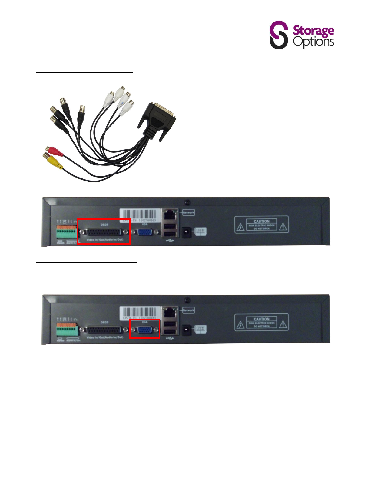
Each of the four cameras connects directly to the DVR via
the DB25 interface cable.
Black BNC: 4x video input – connect to cameras
Yellow BNC: 1x video output to BNC monitor
Red RCA: 1x audio output (not applicable)
White RCA: 4x audio input (not applicable)
Connect a camera to each of the four black BNC cables
and securely attach the DB25 cable to the DB25
connection on the back of the DVR, as shown below.
3.3 – Connecting the DVR to a Monitor
The DVR supports any VGA monitor with resolution of 800x600, 1024x768 or 1280x1024. Please connect the
monitor to the VGA port on the back of the unit.
In addition to a VGA monitor, the DVR also supports a secondary monitor output via the yellow BNC connection on
the DB25 cable (see above).
DB25
VGA
Page 10
Page 10
3.4 – Connecting the DVR to the Mains Supply
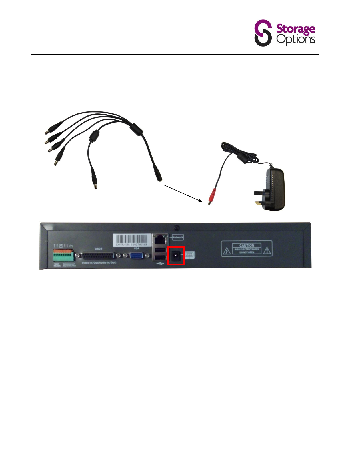
Please connect the included multi mains adapter to the “DC12V5A” connection on the back of the DVR and to each
camera as explained in the diagrams below.
A: 4x power plugs connect to each camera cable
B: 1x power plug to connect to “DC12V5A” on DVR unit
C: 1x power socket connects to mains adapter (below)
Connect the mains adapter to a standard 240V UK 3-pin mains socket. Connect the DVR to the mains last, as it will
automatically switch on when plugged in.
DC12V5A
A
B
C
Page 11
Page 11
BASIC OPERATION
4.1 – Power On / Off
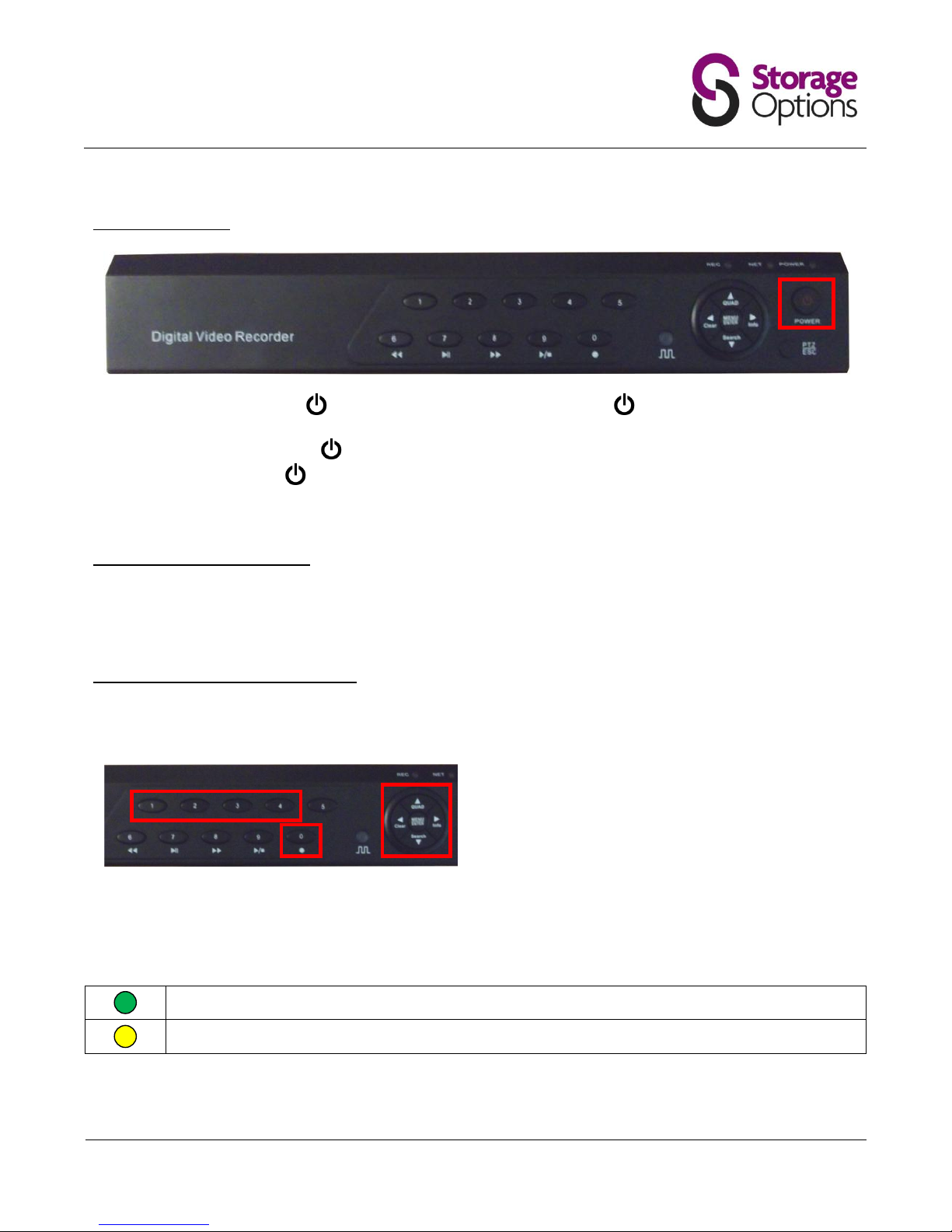
To power on the DVR, press the button once on the main unit, or press the button on the remote control.
To power off the DVR, press the button once and a message stating “Press POWER again to shut down” will
appear on-screen. Press the button again to shut the system down.
Do not shut down the system when a backup is in progress otherwise the backup recording may be lost.
4.2 – Format the Hard Disk Drive
When the DVR unit is powered on for the first time, a message will appear on-screen asking you to format the hard
disk drive (HDD). Please press the “Menu/Enter” button to proceed. Formatting the HDD should only take a few
seconds, after which the DVR is ready for use.
4.3 – Start / Stop Continuous Recording
The DVR is designed to continuously record video streams from up to four cameras. To start continuous recording
on a specific camera, press the corresponding channel number (1 – 4) on the DVR front panel, then press “0”.
To start continuous recording on all connected cameras
simultaneously, press the “Quad” (↑) button to view the
grid, then press “0” to start recording.
Continuous recording can be stopped for each camera or for all four by pressing the “0” button while recording is in
progress.
The record icon will be displayed in one of three colours, depending on the situation:
Recording in progress.
Scheduled recording in progress.
Page 12
Page 12
4.4 – Playback
To play previously recorded video, you must first use the search function to find a date and approximate time to
view. To do this:
1. Press the “Search” (↓) button to access the Search menu.
2. Choose the camera you wish to view (1 – 4) by changing the “Channel” option.
3. To the top right you will see options for choosing date – use the on-screen controls to select the required
date.
4. A list of valid recordings for this date will be displayed below. Move down the list to the required time, then
press “Menu/Enter” to select.
5. On the bottom left of this menu is a “Play” option – highlight this and press “Menu/Enter” to play the video.
6. You may pause, stop, rewind, fast forward and frame advance the playing video using the corresponding
controls on the front panel.
4.5 – Using the Mouse
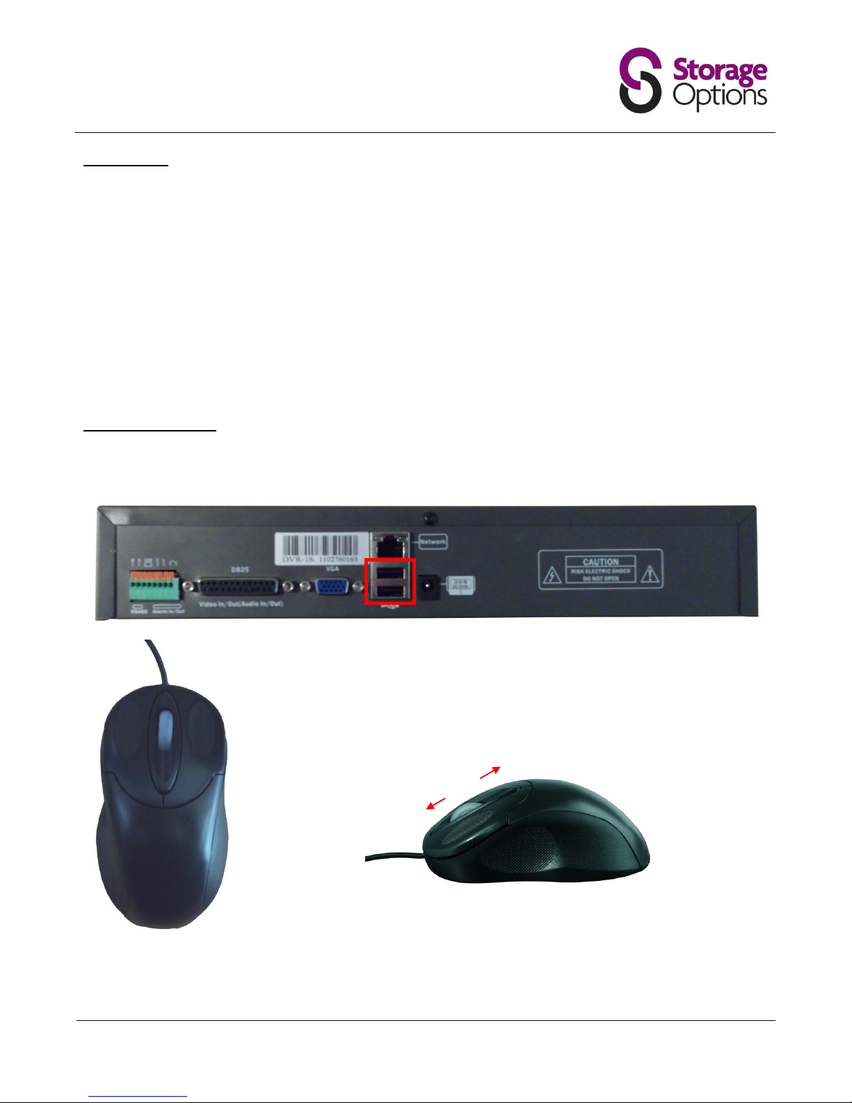
A standard USB mouse is included in the DVR package. You may plug this into either of the two USB ports on the
back of the unit. The mouse can be used to navigate on-screen menus, just as you would with a computer.
Left Button:
Used to select options.
Right Button:
Open quick access menu & return from on-screen menus.
Middle Button:
No function.
Scroll Wheel:
No function.
USB
L M R
Scroll
Page 13
Page 13
4.6 – Remote Control Functions
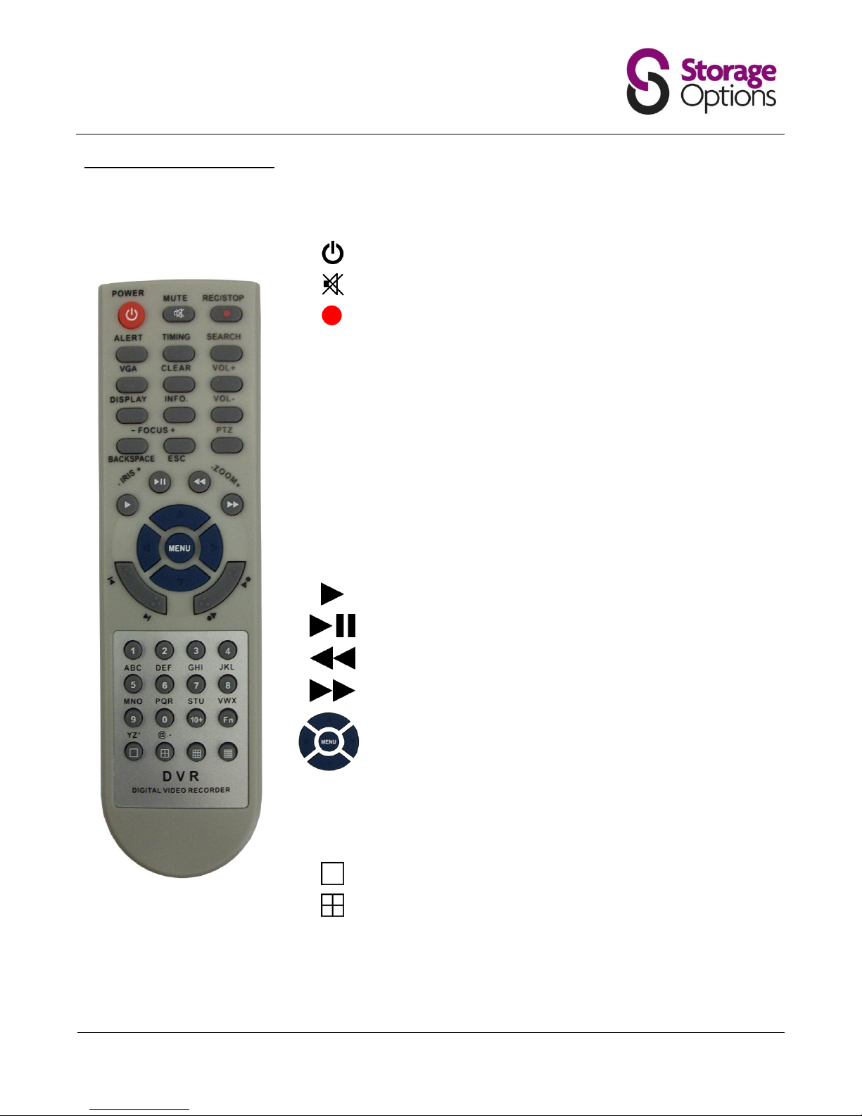
The remote control provides easy access to a variety of commands on the DVR system. Please insert 2x AAA
batteries before use.
Switches the DVR system on / off
Switches audio on / off
Starts and stops continuous recording
ALERT
Turns on / off the alert function.
TIMING
Turns on / off scheduled recording
SEARCH
Search recorded video for specific date to review
VGA
Switch the output resolution of the VGA (monitor) port
CLEAR
Clears the current input
DISPLAY
Switches info on / off (camera names, date, time, etc)
INFO
Switches DVR system info on / off
BACKSPACE
Deletes data entered into menus, one character at a time
ESC
Return from menus
Plays previously recorded footage
Pauses and frame-advances recorded footage
Rewinds video playback 2x. Press again for 4x, 8x, 16x, 32x
Fast forwards video playback 2x. Press again for 4x, 8x, 16x, 32x
↑, ↓, ←, → keys navigate on-screen menus
Menu (Enter) key selects highlighted menu item
1 – 0
Number
Keys
Allows input of numbers where necessary in menus
Allows selection of specific camera (1 – 4)
Allows input of alphabet in menus (press multiple times to
change character)
Switch to single camera view (use numbers to select camera)
Switch to quad camera view mode
Please note, the “Vol +”, “Vol -”, “PTZ” and “Fn” keys have no function.
Page 14
Page 14
BASIC MENU FUNCTIONS
5.1 – Accessing the Menu
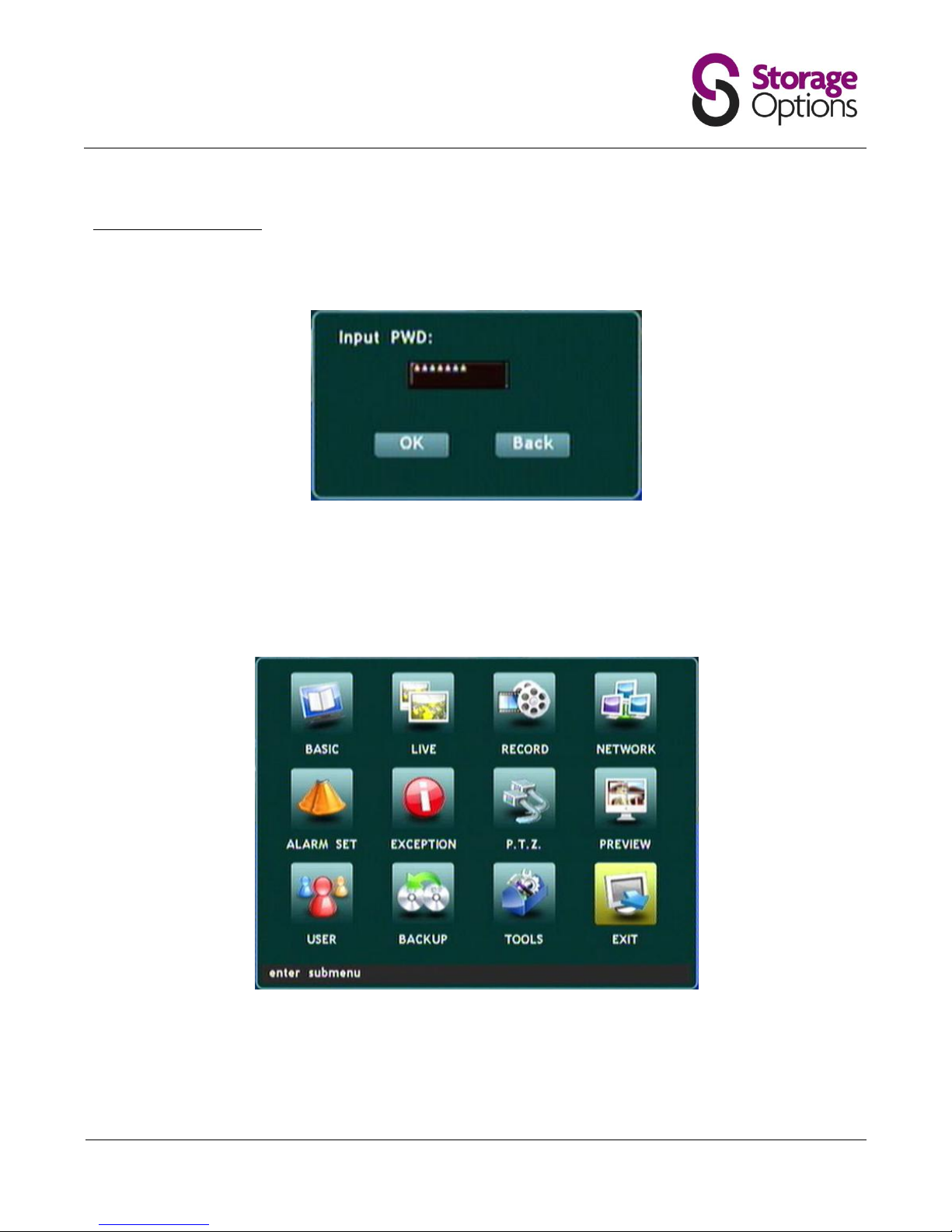
To access the DVR menu, press the “Menu/Enter” button on the front panel or remote control. You will be
prompted to give a pass code.
By default the pass code for the administrator account is “88888888” (you can change this to something more
suitable if you wish).
There are 3 user accounts which all have restricted access to DVR functions. The default pass code for each of the
user accounts is “66666666”. These accounts can be edited and customised when logged in as the admin. See
section 5.10 – User for further details.
All DVR functionality can be accessed and controlled from the main menu. To navigate through the menu, use either
the front panel buttons or the remote control. Use the ↑, ↓, ←, → arrows to navigate through fields, the
“Menu/Enter” button to select the field you wish to edit, “ESC” to return from a field, and the number buttons to
insert text (remote control only).
Page 15
Page 15
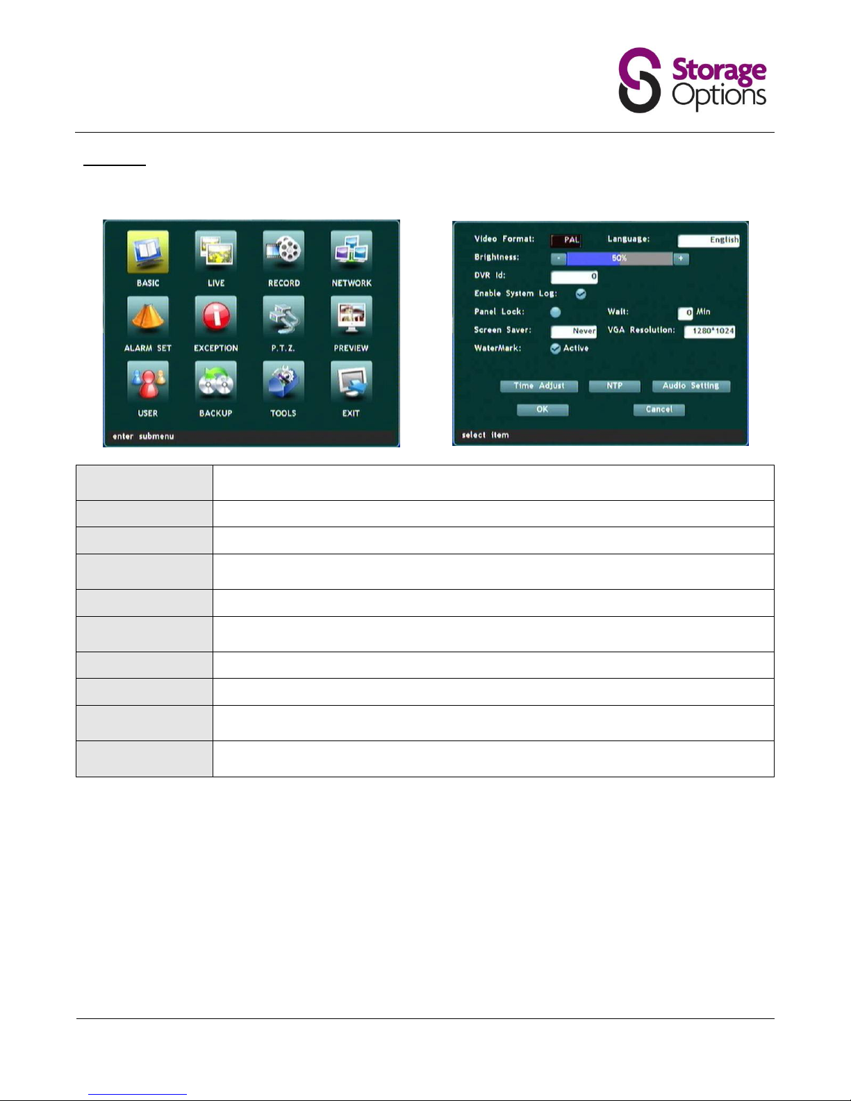
5.2 – Basic
This page allows you to adjust video output, language and screen saver settings.
Video Format:
Choose PAL (UK / Japan) or NTSC (other regions) depending on your location and which type
of monitor you are connecting to.
Language:
Choose from 14 languages.
Brightness:
Choose system-wide brightness for the DVR, scale from 0 - 100% (default 50%).
DVR ID:
If you have more than one Storage Options DVR, you can give the unit an identification
number here.
Enable System Log:
If checked, the DVR will write system events to a log file.
Panel Lock:
Locks the front panel and remote control keys to prevent unauthorised access. Requires the
user to input their password to continue.
Screen Saver:
Set the amount of time before the screen saver activates.
VGA Resolution:
Choose a resolution that matches your monitor (800x600, 1024x768 or 1280x1024)
Time Adjust:
Set the current system date and time. Highlight Year / Month / Day and enter value with
number keys on DVR front panel or remote control.
NTP:
For advanced users only. Allows the user to connect to a Network Time server to synchronise
time settings.
Page 16
Page 16
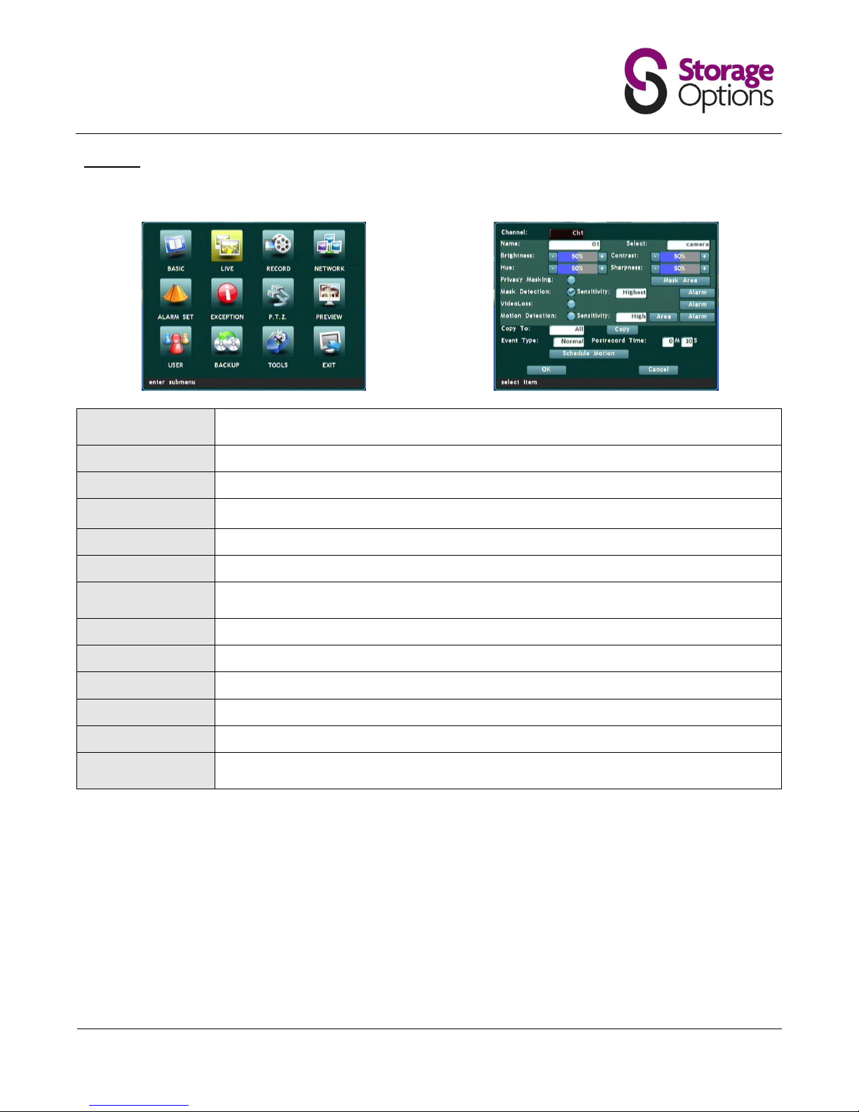
5.3 – Live
Under the live menu you can adjust the settings of individual cameras.
Channel:
Settings on this page refer to an individual camera. Please choose the camera you wish to
change settings for from the Channel menu.
Name:
Type a unique, descriptive name for the selected camera.
Select:
Choose from a list of predefined camera names.
Brightness / Contrast /
Hue / Sharpness:
Adjust image quality settings with these scales (1 - 100%, default 50%).
Privacy Masking:
Mask an area of the image which is NOT to be recorded (e.g. number pad on an ATM).
Mask Area:
Use arrow keys to position and size the masked area.
Mask Detection:
Use this option to mask an area of the image which you do NOT want to trigger a motion
detection alarm (e.g. a swaying tree).
Sensitivity:
Choose the sensitivity of the mask selection function.
Video Loss:
Enable alarm for when loss of video feed occurs.
Motion Detection:
Enable motion detection.
Sensitivity:
Choose the sensitivity of the motion detection function.
Copy To:
Allows the above settings to be copied to other cameras connected to the DVR system.
Schedule Motion:
Use this function if there is a time period when you know there will be motion and you do
NOT want the DVR to trigger a motion alarm (e.g. 9am-5pm in an office).
To set up motion detection:
1. Under “Live”, choose the appropriate channel, then tick the box for “Motion Detection”, and select the
sensitivity.
2. Click the “Area” button and colour the area in RED which you want to trigger a recording.
3. Click the “Alarm” button then select cameras under “Trigger Record” to start recording when motion is
detected on the current channel. (e.g. if you are setting motion detection on channel 1 and you choose
cameras 1, 2 and 3 here, when camera 1 detects motion all three cameras will start recording).
4. On the “Live” menu, choose a suitable “Post-record Time”. Set this to how long you want the recording to
continue after on-screen movement has stopped.
5. Click “Schedule Motion” and make sure the “Active” checkbox is NOT ticked.
Page 17
Page 17
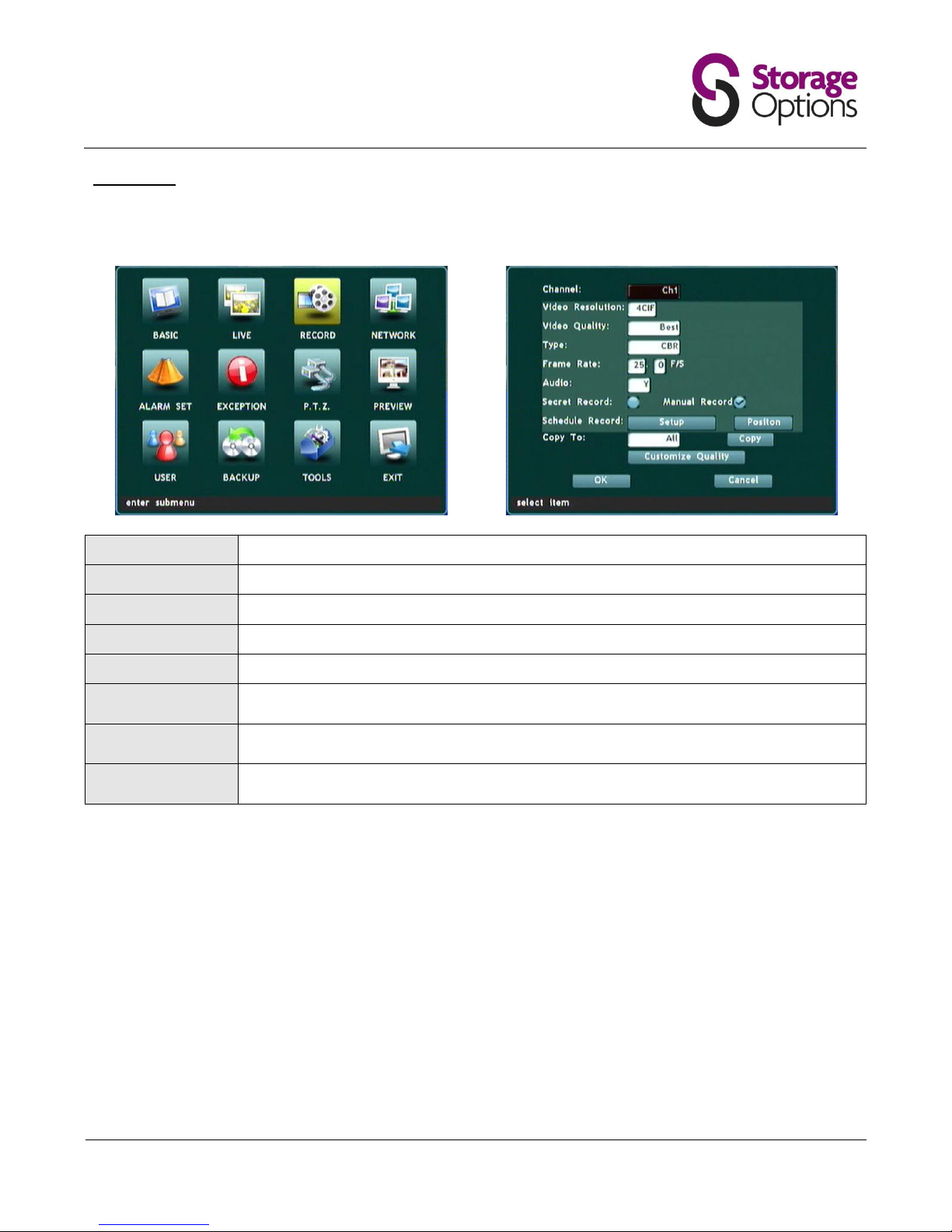
5.4 – Record
This menu allows you to change multiple image quality settings for each camera. The "Copy To" function can be
used to apply the settings from one camera to another or all cameras connected to the system.
Video Resolution:
Choose the image resolution, CIF (lowest quality) to 4CIF (highest quality).
Video Quality:
Choose the overall recording quality.
Type:
Choose from Constant Bitrate (CBR) or Variable Bitrate (VBR).
Frame Rate:
Choose the number of frames to record per second.
Audio:
Not applicable.
Secret Record:
When viewing the camera grid, this function will hide the camera's feed by displaying a blue
screen.
Schedule Record:
Allows the user to set multiple schedules for motion detection-based recording, based on day
of the week and start / stop times.
Customize Quality:
For advanced users. Allows the user to customise the main video stream (DVR) and
secondary stream (network) for the selected camera, as per "Video Quality" modes.
Please note, higher quality settings will cause more hard disk capacity to be used.
Page 18
Page 18
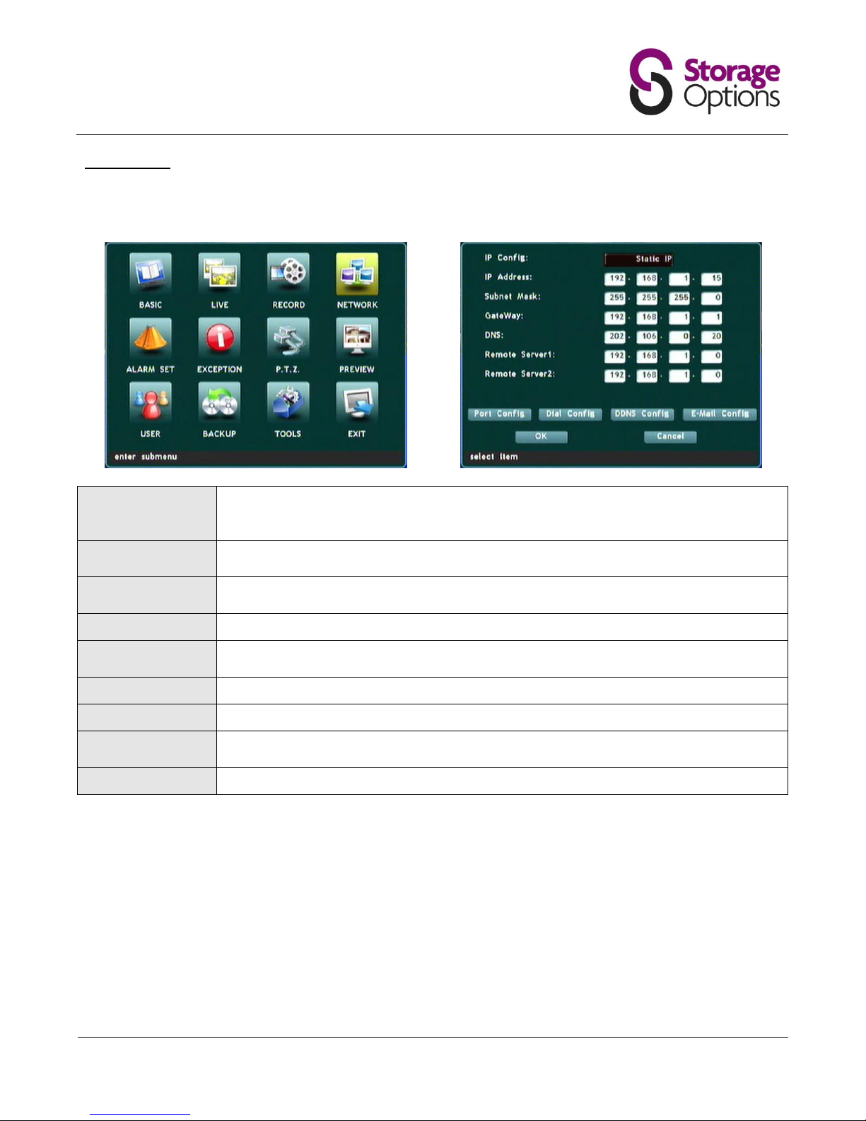
5.5 – Network
Here you can choose how the DVR connects to your network. Please connect the DVR via RJ45 LAN cable before
changing these settings. The following settings only need to be configured if you choose "Static IP".
IP Config:
"DHCP" allows the DVR to automatically receive network settings. Set to "Static IP" if you
would like to configure these settings manually. If you are new to network configuration, it is
strongly advised to leave this on DHCP.
IP Address:
This should be unique to the DVR unit, but within the same subnet as the network
(e.g. 192.168.1.x).
Subnet Mask:
Enter the subnet mask here. Refer to your router's operating instructions if you are unsure
what value this should be.
Gateway:
This should be the address for your default gateway (e.g. router).
DNS:
Provide the address of a Domain Name Server (DNS) here. Your router may also provide
DNS.
Port Config:
For advanced users only.
Dial Config:
For advanced users only.
DDNS Config:
Enter details for your DDNS account here if you wish to remotely access the DVR over the
Internet. Please note, the password must contain only numeric characters.
E-Mail Config:
For advanced users only.
Page 19
Page 19
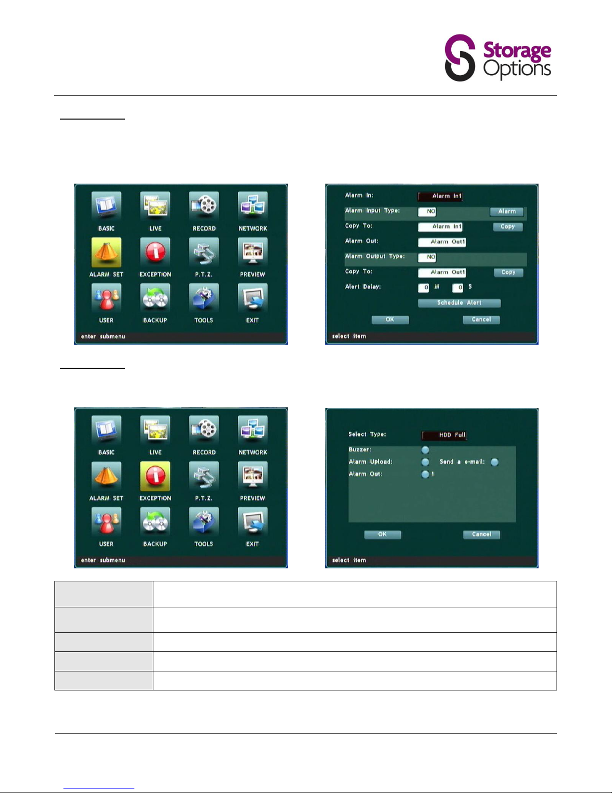
5.6 – Alarm Set
This page is for advanced users only, and allows the DVR to be connected to a building alarm system to provide
automatic activation when the DVR's own alarm (e.g. motion detection) is triggered. Due to the nature of connected
alarms all being configured differently, we cannot provide support on this feature.
5.7 – Exception
This page allows you to set alerts for system malfunctions.
Select Type:
Choose from HDD full, HDD error, IP conflict, network error, access error, PAL/NTSC error,
video error.
Buzzer:
If this option is checked, a high-pitched buzz will emit from the DVR when the alarm is
triggered.
Alarm Upload:
For advanced users only.
Send an E-Mail:
For advanced users only (requires an e-mail server).
Alarm Out:
For advanced users only.
Page 20
Page 20
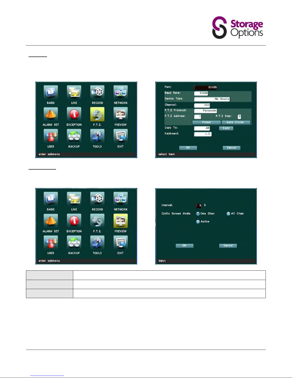
5.8 – PTZ
The cameras within the Storage Options CCTV System are static and designed to be mounted facing a specific
direction. As such, they do not feature Pan / Tilt / Zoom functionality, so this page is not applicable.
5.9 – Preview
This page allows the user to set a cycle of video feeds over a specific time interval.
Interval:
Set the time each camera should be displayed before moving onto the next (in seconds).
Cyclic Screen Mode:
Choose which views should be cycled on the loop of feeds.
Active:
Check the active option to activate cyclic view mode.
Page 21
Page 21
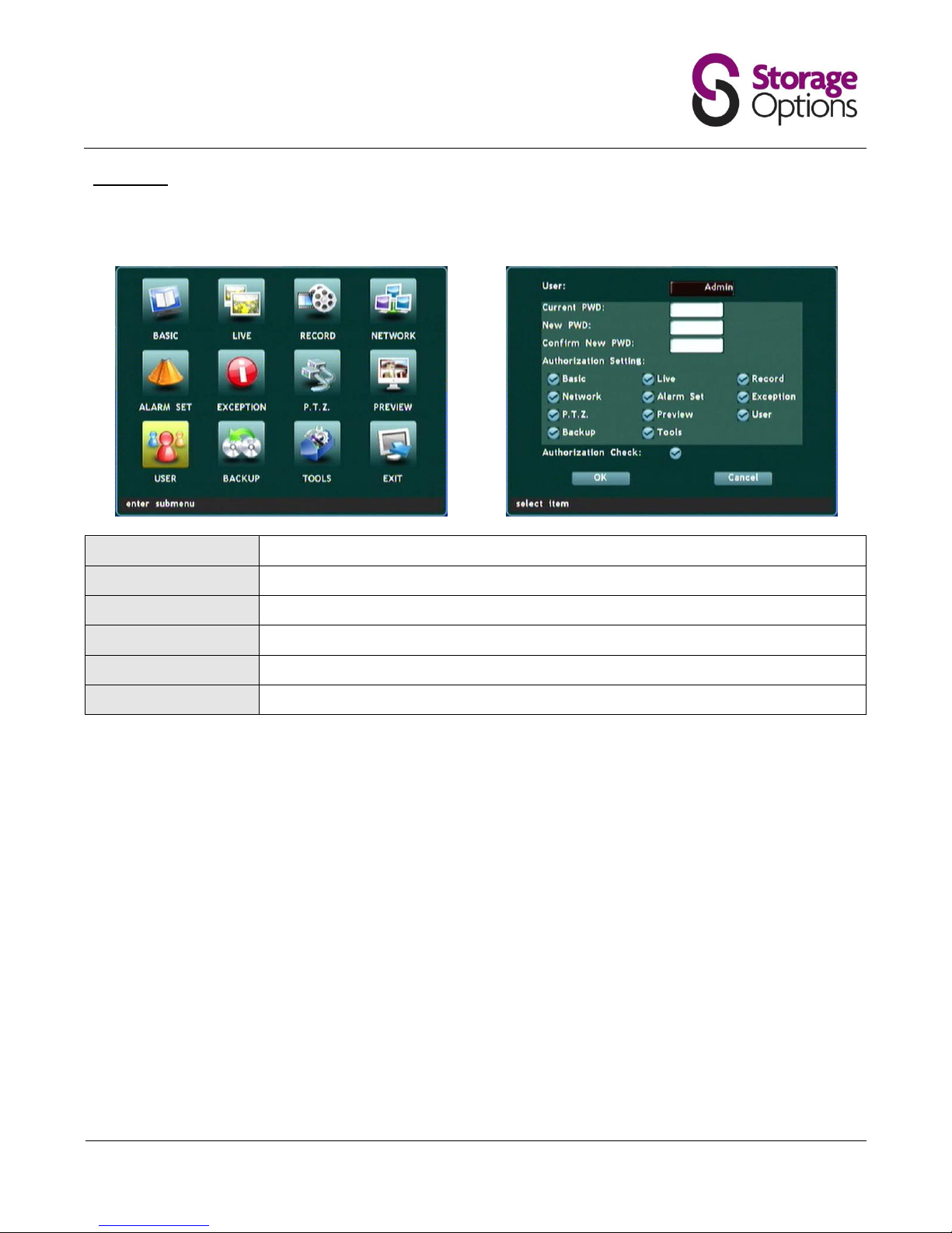
5.10 – User
This page allows the user to make changes to accounts and access levels. You may set up multiple users to have
access to different features of the DVR.
User:
Choose the account you would like to edit.
Current Pwd:
Only enter the current password here if you intend to change it in the next field.
New Pwd:
Enter a new password here if you wish to change it.
Confirm New Pwd:
Repeat the new password in this field to confirm.
Authorization Setting:
Choose pages that the account holder will be able to access.
Authorization Check:
When enabled, always asks for the password before allowing menu access.
Page 22
Page 22
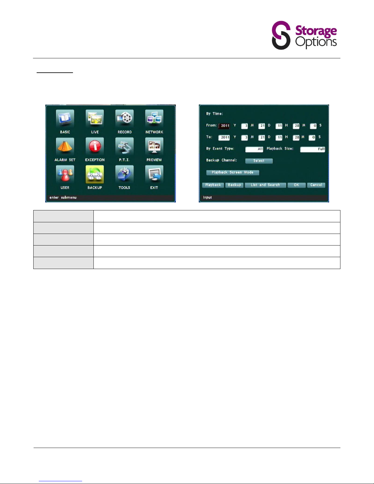
5.11 – Backup
This page allows the user to backup video recordings from all four cameras to a USB device, such as flash drive or
portable HDD. Before using this feature, please connect your USB device to one of the ports on the back of the DVR.
From:
Select a date and time to start the backup from.
To:
Select a date and time to end the backup.
By Event Type:
Choose whether all, alarm, or normal recordings should be backed up to the external drive.
Playback Size:
Choose full or original video playback size.
Backup Channel:
Select which camera (1 – 4) to backup.
Once these fields are complete, move down to the "Backup" option and press "Menu/Enter". This will back-up the
selected recordings to the external device. Please be patient as this may take a while, depending on the time range
selected and quality of recordings.
Page 23
Page 23
5.12 – Tools
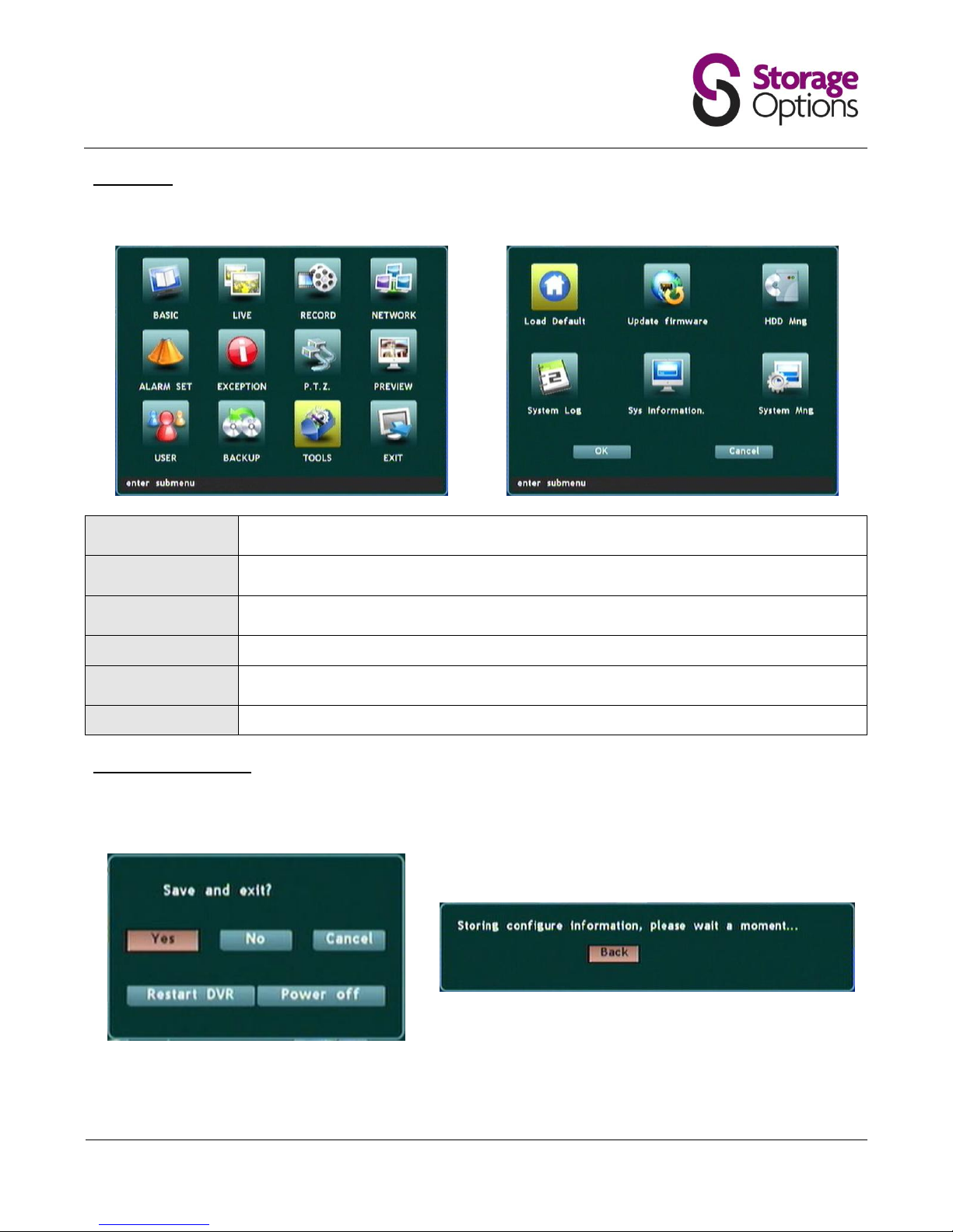
This page contains various system tools which enable the administrator to manage the DVR.
Load Default:
Loads default configuration values for the DVR. Please only select if you wish to reset
configuration to factory settings!
Update Firmware:
For advanced users only. Enter the network location of a firmware update file to update the
system.
HDD Mng:
Shows a list of installed HDDs and allows the selected HDD to be formatted. Please note, if
the disk is formatted all video recordings will be lost!
System Log:
Displays the system log files which show logins, updates, alarms, backups, etc.
Sys Information:
Gives an overview of current system configuration. This page is for information only and
cannot be edited.
System Mng:
You may restart or power off the DVR from this menu.
5.13 – Exiting the Menu
To save any changes that have been made in previous menus, you cannot simply exit the menu. You must move to
the “Exit” icon and press “Menu/Enter”.
You will be prompted to “Save and exit”. Choose the appropriate option and press the “Menu/Enter” button again
to return to camera view.
Page 24
Page 24
NETWORK FUNCTIONS
6.1 – Connecting the DVR to a Network
The Storage Options CCTV System can be connected to a network and many of it’s functions can be used on a
computer.
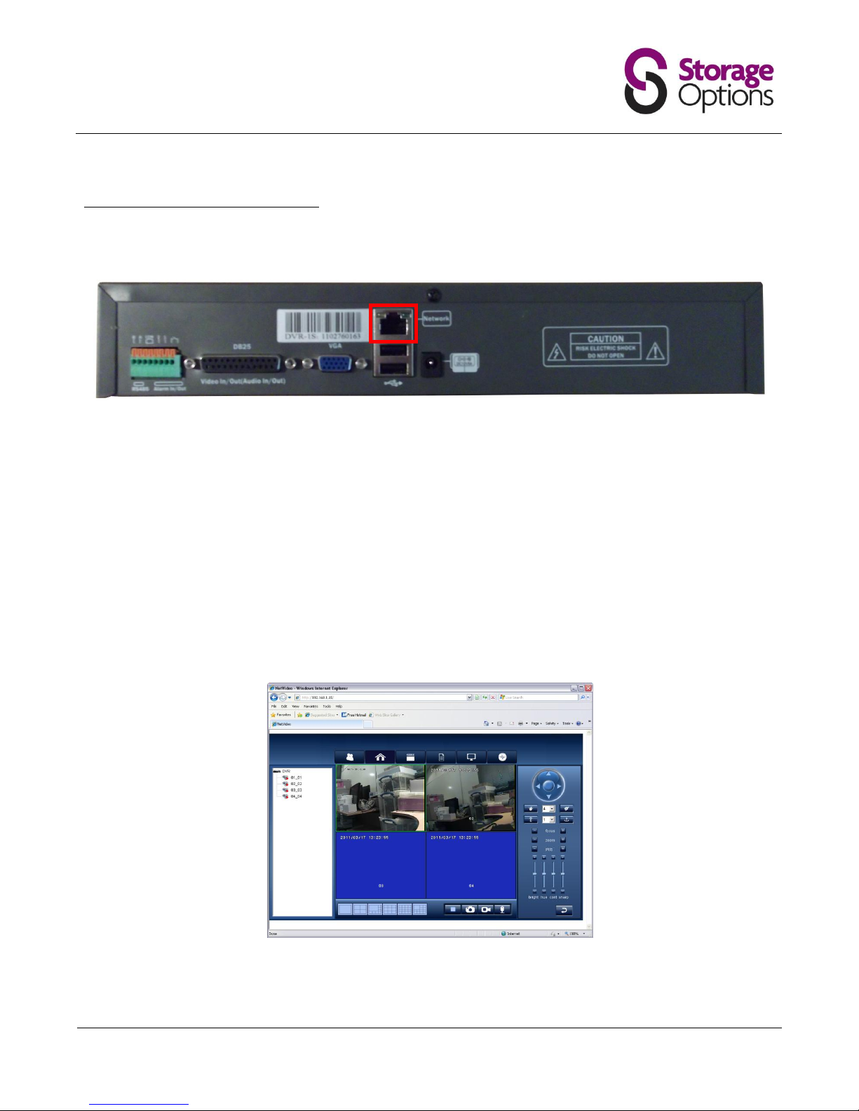
1. Connect an RJ45 network cable to the “Network” port on the back of the DVR.
2. Connect the other end of the network cable to the network router.
3. If the router has a DHCP server, the DVR should automatically configure itself (see section 5.5 – Network). If
address information is not automatically configured, you will need to set up a static configuration. See your
router’s manual for more information on what values you should use.
4. Take note of the DVR’s “IP Address”. You will need this to access the DVR from a computer.
5. On a computer which is attached to the same network, open Internet Explorer and in the address bar type
“http://” followed by the DVR’s IP address (e.g. http://192.168.1.15).
Please note, you must use Internet Explorer as the CCTV system uses ActiveX controls which are exclusive to this
browser. Other browsers such as Firefox, Chrome and Safari, are not supported.
6. If you are prompted to download or allow access to an ActiveX control or piece of software, please allow this
action. CCTV browser software will be transferred from the DVR to your browser.
Once the software has finished installing, you will be presented with the CCTV software in your browser window.
Please read the following instructions to understand how to use this software.
Network
Page 25
Page 25
6.2 – View and Record Live Cameras
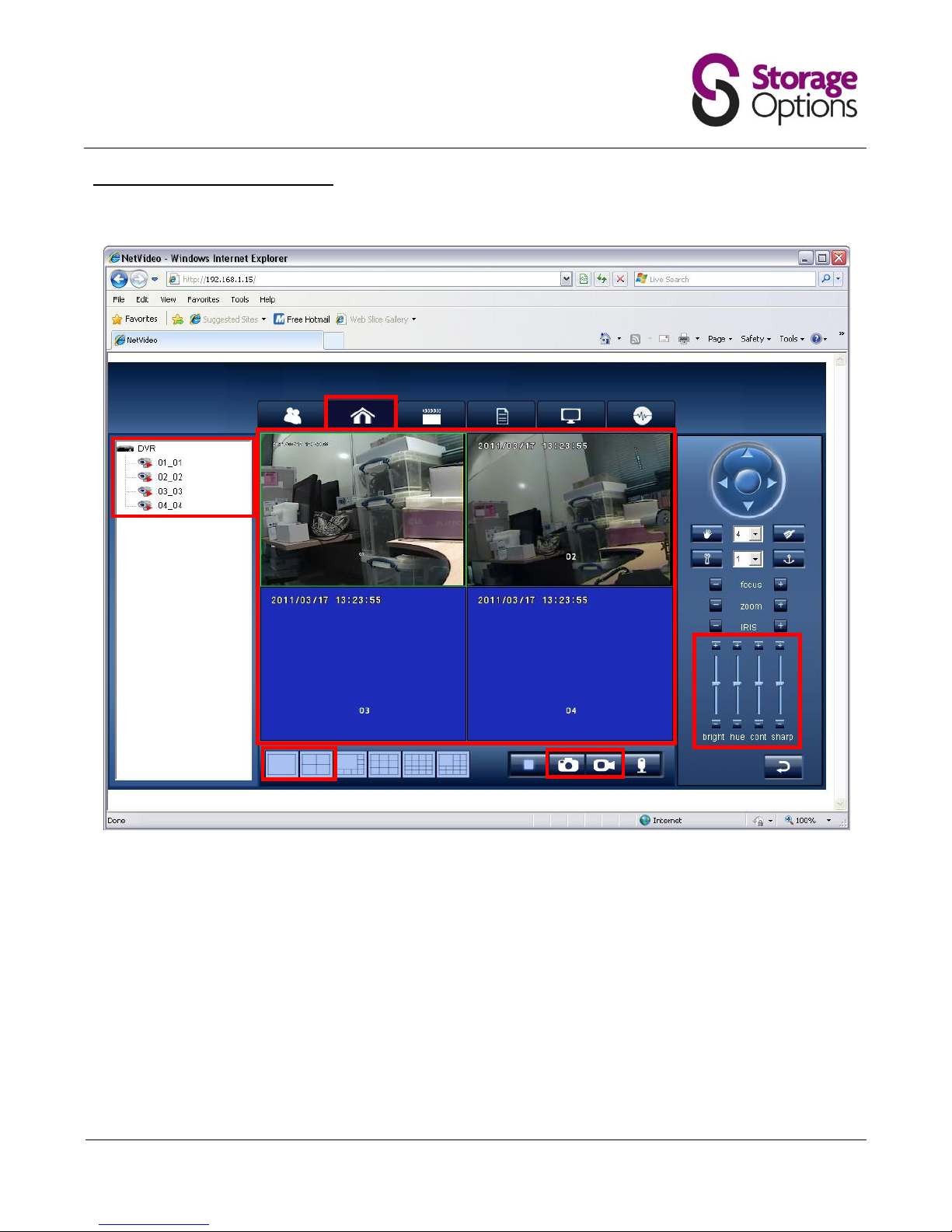
Once connected to the camera’s Web server, you can view all four camera feeds and also perform other functions.
1. Click the “Home” icon on the menu bar.
2. Double-click or drag each camera to the main window (3) to display the live feed on screen.
3. You can adjust brightness, contrast, hue and sharpness for the cameras with this control panel.
4. The main window displays all activated cameras.
5. Choose how to view the cameras with the grid layout buttons. You can also display a camera full-screen by
double clicking on the video playback window.
6. Take a snapshot or start recording to your computer’s HDD using these controls (please note, depending on
your operating system’s security settings, these functions may not work).
2
1 3 4 6 5
Page 26
Page 26
6.3 – Playback of Recordings on the DVR
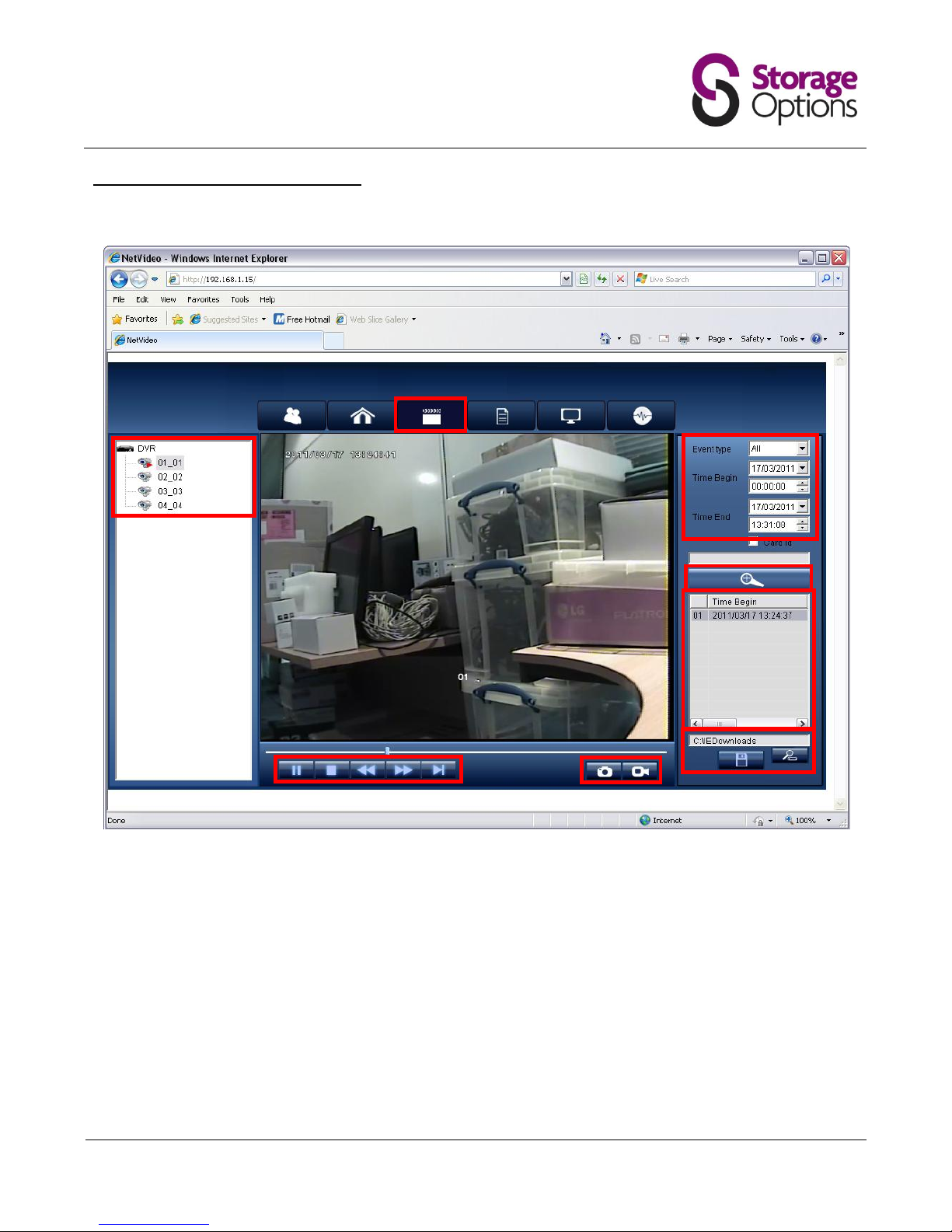
Recordings that have been made on the DVR can be viewed on a computer via the browser interface.
1. Click the “Playback” icon on the menu bar.
2. Choose the required camera from the list.
3. Select which event type you would like to view, as well as the dates and times to restrict the search to.
4. Press the “Search” button. The search results will be displayed in the log window (5).
5. From here you can double click an item to load it into the main window and use the transport controls (7) to
play, pause, fast forward and rewind the video.
6. Choose a location to store video files to on your computer, then click the “Save” icon to transfer the selected
files from the DVR.
7. Use the transport buttons to control video playback.
8. Take a snapshot or start recording to your computer’s HDD using these controls (please note, depending on
your operating system’s security settings, these functions may not work).
1
2 3 4 5 7
8
6
Page 27
Page 27
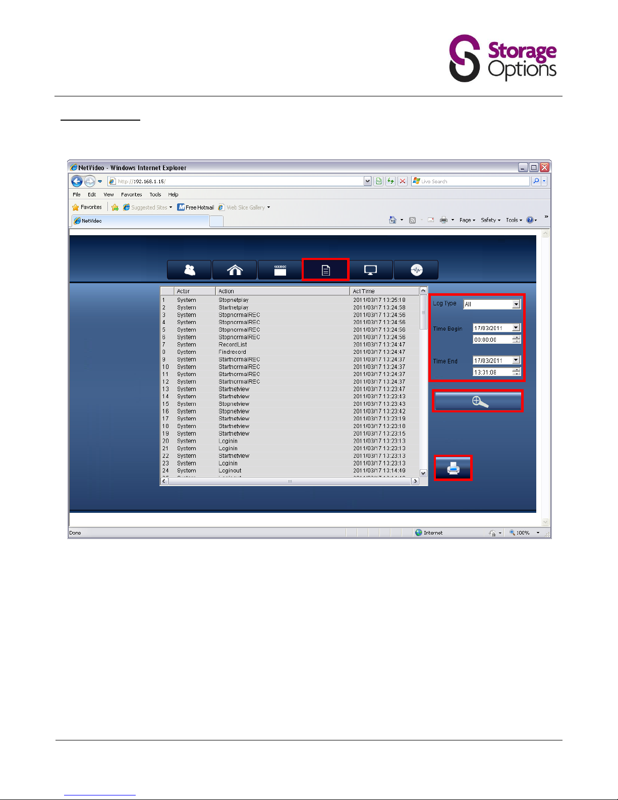
6.4 – Viewing Logs
The system log is a list of all actions taken on the DVR, such as start / stop record, errors, alarms, account logins, etc.
1. Click the “Log” icon on the menu bar.
2. Select which log type you would like to view, as well as the dates and times to restrict the search to.
3. Press the “Search” button. The search results will be displayed in the main window.
4. If you have a printer attached to your computer, you can print a paper copy of the log.
1 2 3
4
Page 28
Page 28
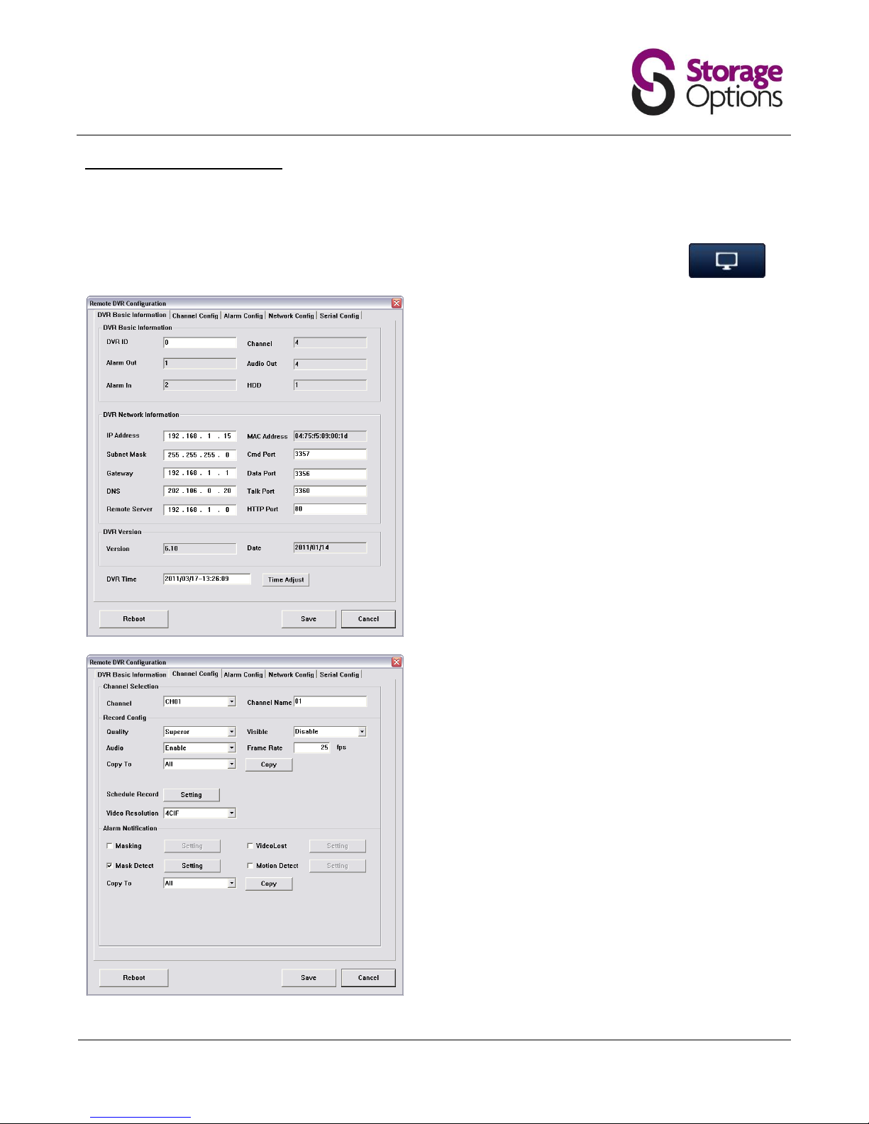
6.5 – Remote DVR Configuration
Configuration for the DVR (covered in section 5 – Menu Functions) can also be done via a computer, across the
network.
From the main interface in your Web browser, click the top menu button (see image, right) to
open the Remote DVR Configuration window.
DVR Basic Information
This page contains basic settings for DVR ID and networking.
For more information, please refer to these sections:
5.2 – Basic
5.5 – Network
Channel Config
This page contains video quality and recording schedule
options.
For more information, please refer to these sections:
5.4 – Record
Page 29
Page 29
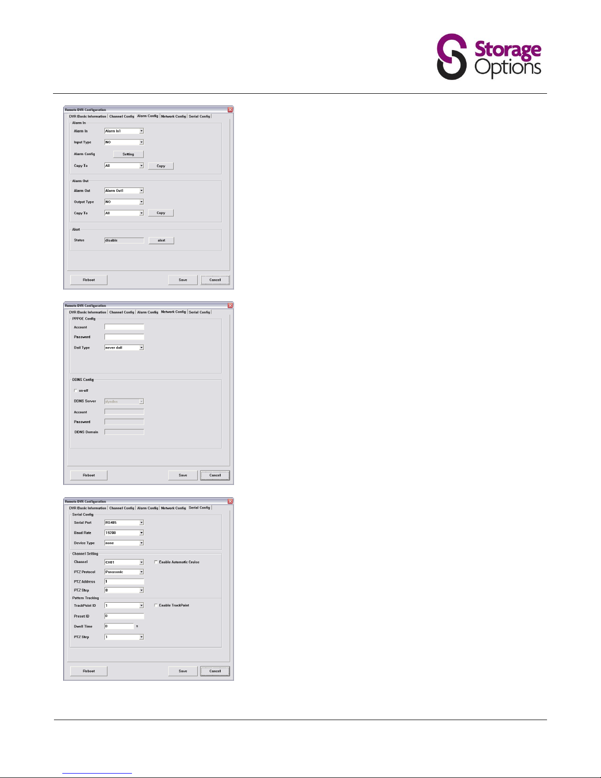
Alarm Config
This page is for advanced users only, and allows the DVR to be
connected to a building alarm system to provide automatic activation
when the DVR's own alarm (e.g. motion detection) is triggered.
Due to the nature of connected alarms all being configured differently,
we cannot provide support on this feature.
Network Config
This page allows you to attach a DDNS account to the CCTV DVR for
remote access across the Internet.
For more information, please refer to these sections:
5.5 – Network
Serial Config
The functions in this section are not applicable to this model, as the
cameras do not support PTZ.
For more information, please refer to these sections:
5.8 – PTZ
Page 30
Page 30
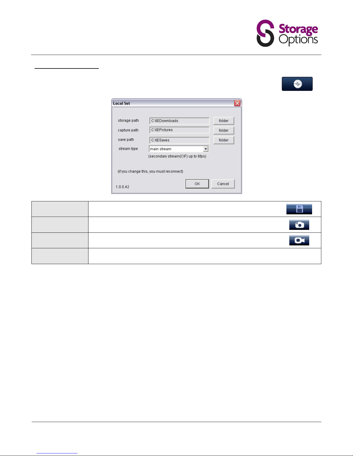
6.6 – Setting Local Folders
The “Local Set” window allows you to set the default folders for video and frame captures to be
saved to. Click the “Local Set” button (pictured right) to open the settings menu.
Storage Path:
Set the folder to save video transfers (from DVR to computer).
See section 6.3 – Playback of Recordings on the DVR for this function.
Capture Path:
Set the folder to save to when the “Screen Capture” button is pressed.
Save Path:
Set the folder to save to when the “Video Capture” button is pressed.
Stream Type:
Choose the stream type (main / secondary) to be viewed from the DVR.
Page 31
Page 31
USING ZMEYE FOR ANDROID
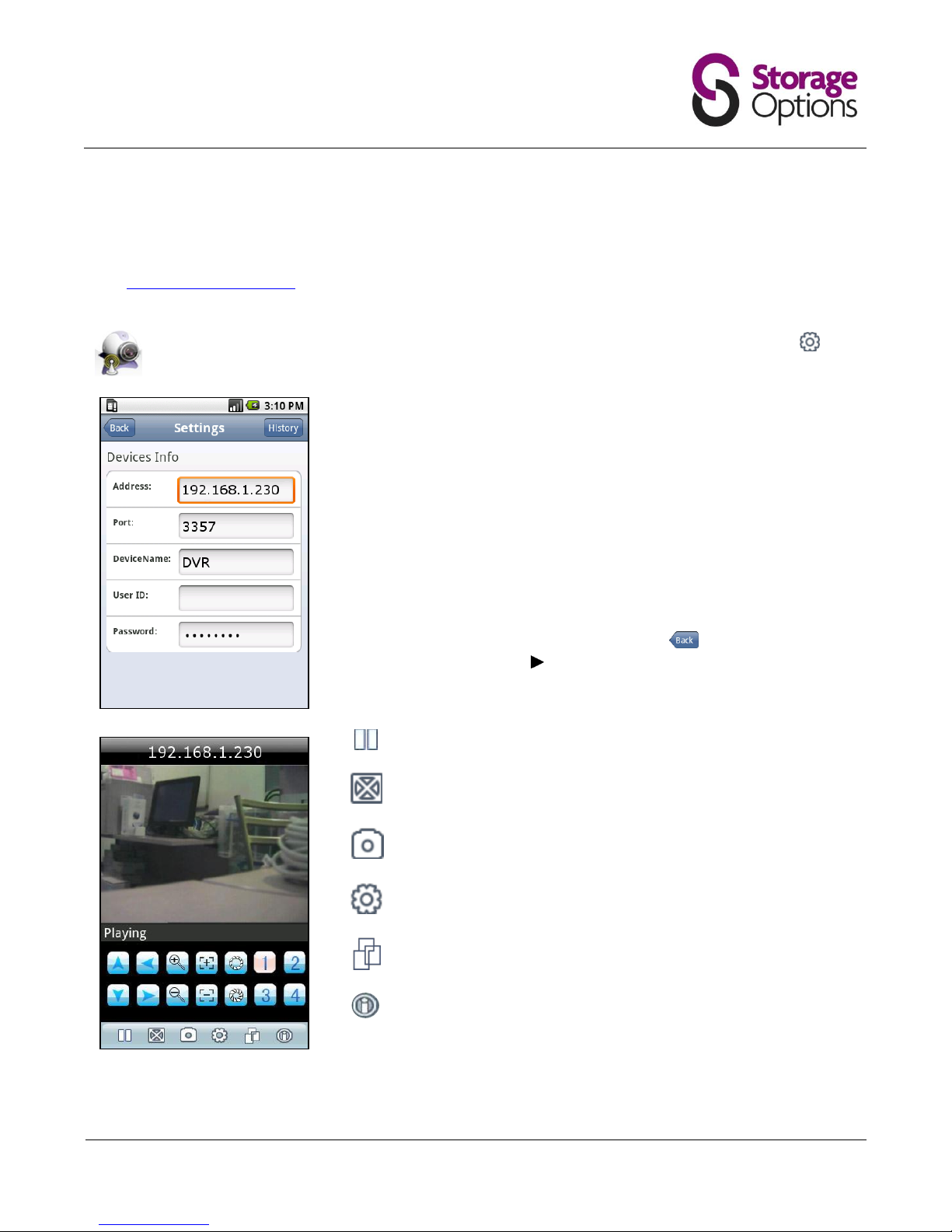
ZMEye is an application for Android (and iPhone) which can be used to view cameras on your network-connected
DVR. Your Android device must also be connected to the network for this service to function.
Visit www.storageoptions.com to download ZMEye software. Copy it to your Android device in the usual manner
and install the program.
Touch the ZMEye icon to load the program. On the bottom of the screen there is a settings icon:
Press this to enter the configuration menu:
Address:
Port:
DeviceName:
User ID:
Password:
Enter the IP address of your DVR system here.
See Section 5.5 – Network for more information.
This must match with the port assigned to the DVR system.
Enter a friendly device name (not mandatory).
Leave this field blank.
Enter the pass code of the DVR account (default 88888888 for
the admin account).
Once these fields have been completed, press the button to return to the
camera screen, then press the button to connect to the camera stream.
Pause / play the live video stream.
View the video in full screen mode.
Take a snapshot of the video (stored on your Android device’s
memory card).
Enter the settings menu (see above)
Change camera group (1-4, 5-8, 9-12, 13-16).
Only cameras 1-4 are applicable on the Storage Options DVR.
Shows information about the ZMEye software.
1-4
Select the camera you wish to view.
ZMEye is also available for Apple iPhone products. Please visit the iTunes store to download.
Page 32

Page 32
TROUBLESHOOTING
Q
Why doesn’t the DVR start when I press the power button?
A
Check the DVR is connected to the mains and that the socket switch is set to the “on” position.
Q
Why is the boot process slow?
A When the DVR boots, it will search through the database of recorded data. If there is a lot of recorded data,
the boot process may slow down.
Q
Why does the DVR not respond to the remote control?
A
Check the batteries to make sure they are not out of date, and check they are correctly oriented.
Q
Why is the image displayed on the monitor in black & white?
A
Check video output settings; if incorrectly set to PAL / NTSC, the image will be black & white.
Q
Why does my monitor not display an image?
A
For approximately 30 seconds when the DVR is booting, no image is displayed. After this time, the image
should be displayed. If not, please check the monitor is turned on and that the VGA / BNC cable is connected
securely. Check the monitor is connected to a mains supply.
Q
Why do my recorded videos have no audio?
A
The outdoor and dome cameras included in the Storage Options CCTV System do not have audio capabilities.
Page 33
Page 33
APPENDIX - PRODUCT SPECIFICATIONS
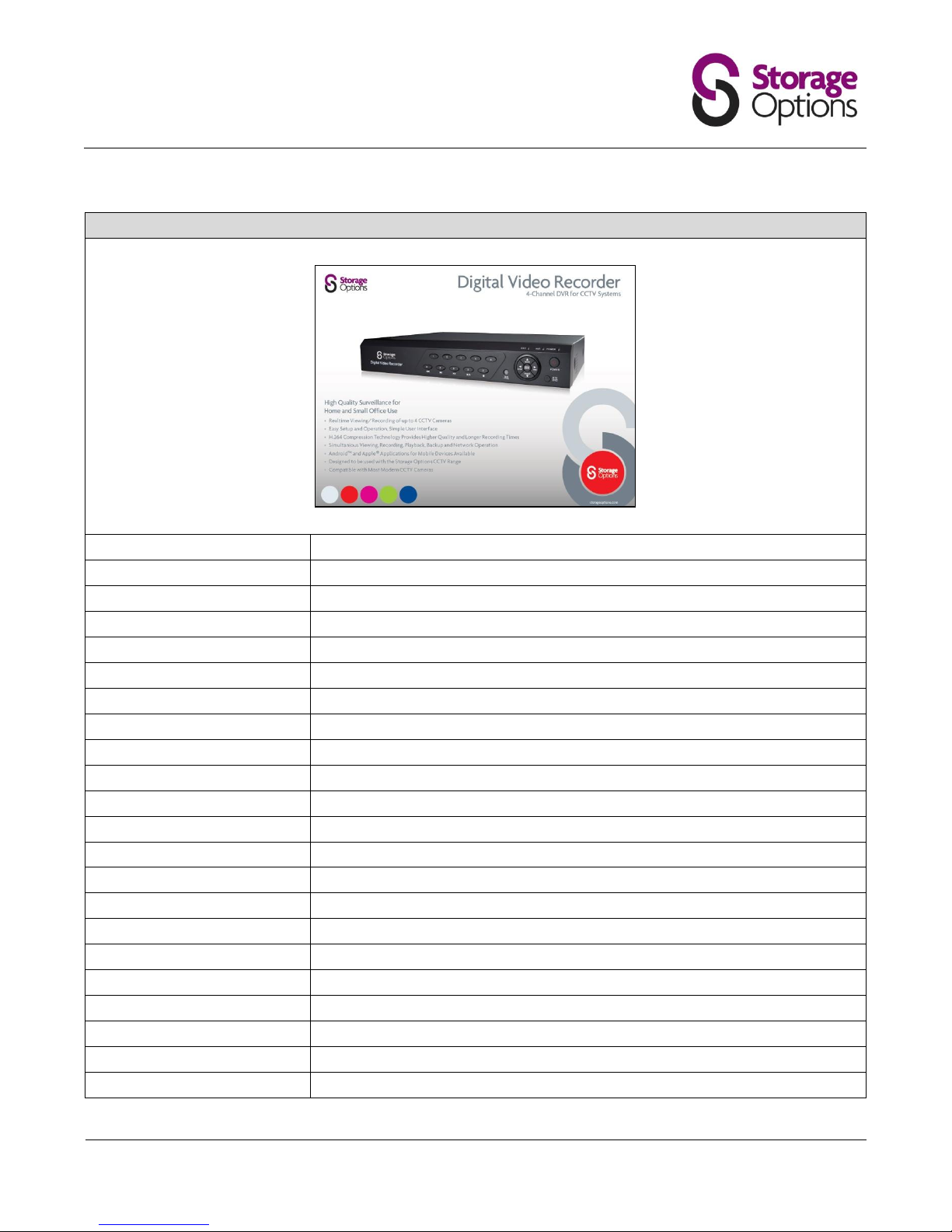
Digital Video Recorder (DVR)
Compression Standard:
H.264
Video Input:
4 channel
Video Output:
1 channel
Audio Input:
4 channel
Audio Output:
1 channel
Resolution (Display / Record):
PAL: 704 x 576 / 352 x 288; NTSC: 704 x 480 / 352 x 240
Video Frames:
PAL: 25fps; NTSC: 30fps
VGA Interface:
1 channel
Alarm Input:
2 channel (switching capacity)
Alarm Output:
1 channel (switching capacity)
Alarm:
Alarm sensor, Video dynamic detecting alarm, Video loss alarm, Disk full alarm
Network:
Ethernet (10/100Mbps), WAN and ADSL
Monitoring Methods:
Internet Monitoring, Phone monitoring, E-mail function
Control:
Mouse, Remote control, DVR control
Backup:
USB and Network
HDD:
1 bay, up to 2TB
Security Feature:
Password protection
Power Supply:
DC12V, 3-5A
Operating Temperature:
-50oC – +50oC
Humidity:
< 90%
Device Dimensions:
320 x 255 x 55mm (WxDxH)
Weight:
Net: 1.5KG; Gross: 2.0KG
Page 34
Page 34
APPENDIX - PRODUCT SPECIFICATIONS
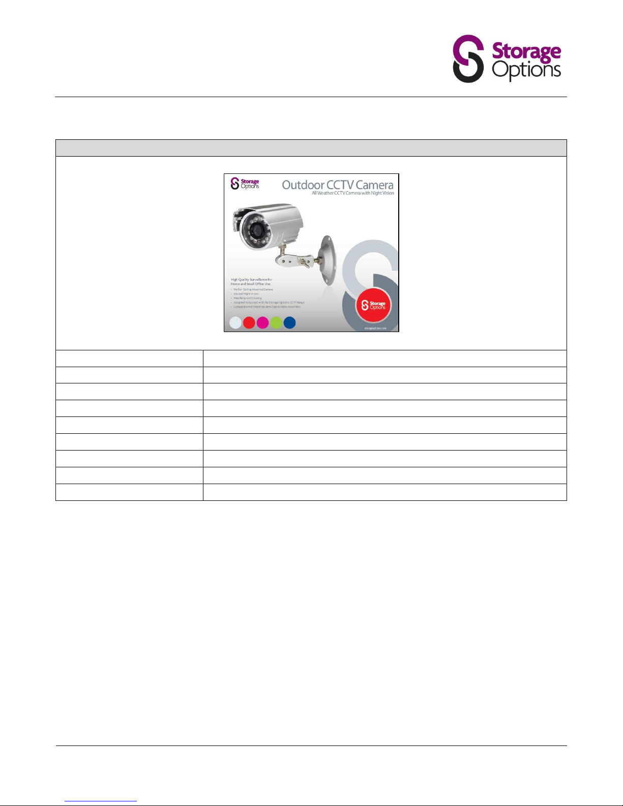
Outdoor Camera
Image Sensor:
1/4” SONY Super HAD CCD
Effective Pixels:
PAL: 500(H) x 582(V); NTSC: 510(H) x 492(V)
Signal System:
PAL / NTSC
Horizontal Resolution:
420 TV Lines
Lens:
6mm Standard
Minimum Illumination:
0 Lux (IR on)
Video Output:
1.0V p-p 75Ω (BNC)
Power Requirement:
DC12V / 140mA, 300mA (IR on)
Weatherproof:
Meets IP65 Standard
Page 35
Page 35
APPENDIX - PRODUCT SPECIFICATIONS
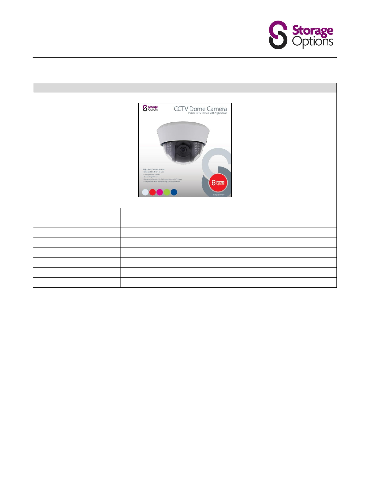
Dome Camera
Image Sensor:
1/3" SONY Super HAD CCD
Effective Pixels:
PAL: 500(H) x 582(V); NTSC: 510(H) x 492(V)
Signal System:
PAL / NTSC
Horizontal Resolution:
420 TV Lines
Lens:
3.6mm Standard
Minimum Illumination:
0 Lux (IR on)
Video Output:
1.0V p-p 75Ω (BNC)
Power Requirement:
DC12V
Page 36
Page 36
Storage Options Analogue CCTV System
Made in Taiwan
 Loading...