


2
CAUTION
RISK OF ELECTRIC SHOCK
DO NOT OPEN
TO REDUCE THE RISK OF ELECTRIC SHOCK,
DO NOT REMOVE THE COVER.
NO USER SERVICABLE PARTS INSIDE.
REFER SERVICING TO QUALIFIED PERSONNEL.
The lightning flash with arrowhead symbol, within an equilateral
triangle, is intended to alert the user to the presence of non-
insulated “dangerous voltage” within the product’s enclosure that
may be of sufficient magnitude to constitute a risk of electric shock.
The exclamation point within an equilateral triangle is intended to
alert the user to the presence of important operating and
maintenance (servicing) instructions in the literature accompanying
the appliance.
WARNING:
TO PREVENT FIRE OR SHOCK HAZARD, DO NOT
EXPOSE THIS UNIT TO RAIN OR MOISTURE
CAUTION:
TO PREVENT ELECTRIC SHOCK, ENSURE THE PLUG
IS FULLY INSERTED INTO A MAINS SOCKET

3
IMPORTANT SAFEGUARD
All lead-free products offered by the company comply with the requirements of the
European law of the Restriction of Hazardous Substances (RoHS) directive, which means our
manufacturing processes and products are strictly “lead-free” and without the hazardous
substances cited in the directive.
The crossed-out wheeled bin mark symbolizes that within the European Union the product
must be collected separately at the product’s end-of-life. This applies to your product and
any peripherals marked with this symbol. Do not dispose of these products as unsorted
municipal waste. Contact your local dealer for procedures for recycling this equipment.
DISCLAIMER
We reserve the right to revise or remove any content in this manual at any time. We do not warrant or assume any
legal liability or responsibility for the accuracy, completeness, or usefulness of this manual. The content of this
manual is subject to change without notice.
RECOMMENDATIONS
AVOID DUSTY LOCATIONS:
INSTALL IN VENTILATED SPACE:
DO NOT EXPOSE TO MOISTURE:
DO NOT DROP:
DO NOT OPEN CHASSIS:
Excessive build-up of dust may cause the unit to fail.
Ensure adequate airflow around the DVR to prevent overheating.
Exposing the unit to water poses high risk of electric shock.
Doing so could damage internal components.
No user-serviceable parts inside.
DEFAULT PASS CODE INFORMATION
By default, pass codes are disabled on the system. You do not need to enter a pass code when accessing any menus.
For security purposes, it is highly recommended to enable pass codes via the Password Menu.
WARRANTY AND TECHNICAL SUPPORT
To help you make the most of this product you’ll find a host of information including full product manuals, FAQ,
troubleshooting guides and a support service if you have specific questions, available at our support website:
www.storageoptions.com/support.
This product is also backed by a 12 month warranty in the unlikely event of something going wrong. More
information and warranty registration is available at www.storageoptions.com/warranty.
storageoptions.com/support/
support@storageoptions.com

4
TABLE OF CONTENTS
QUICK START GUIDE
6
1.1 – Basic Connectivity
1.2 – Wall Mounting A Camera
1.3 – Power Connection Diagram
6
7
8
OVERVIEW
9
2.1 – System Overview
2.2 – Environment Adaptability
2.3 – Recording Capacities
9
9
9
CONVENTIONS USED IN THIS MANUAL
10
PACKAGE CONTENTS
10 SYSTEM CONNECTION
11 BASIC OPERATION
12
6.1 – Front Panel
6.2 – Rear Panel
6.3 – Remote Control
6.4 – Mouse Control
6.5 – Using The Sub Menu
12
13
14
15
15
POWER ON / OFF
16 SYSTEM LOGIN
17
8.1 – Pass Codes
8.2 – Menu Navigation
17
17 MAIN MENU
9.1 – Record Menu
9.2 – Alarm Menu
9.3 – System Menu
9.4 – Advanced Menu
9.5 – Info Menu
9.6 – Logout Menu
19
20
21
22
23
24

5
TABLE OF CONTENTS (CONTINUED)
SET SYSTEM DATE & TIME
25 FORMAT THE HARD DISK DRIVE
26 CONFIGURE RECORDING OPTIONS
27
12.1 – Record Configuration
12.2 – Encoding Options
27
28 MOTION DETECTION RECORDING
29
PLAYBACK MODE
30
FILE BACKUP
31 NETWORK SETTINGS
33 NETWORK CONNECTIVITY
34
17.1 – Using The Net Surveillance Interface
17.2 – Main Screen
17.3 – Live View
17.4 – Recording
17.5 – Screen Capture
17.6 – Playback
17.7 – PTZ Control
17.8 – Remote DVR Setup
35
36
37
38
39
40
41
41 REMOTE ACCESS
42 HARD DISK DRIVE INSTALLATION
43
TROUBLESHOOTING
44
PRODUCT SPECIFICATION
45 WARRANTY AND PRODUCT SUPPORT
46

6
QUICK START GUIDE
1.1 – BASIC CONNECTIVITY
To get started quickly with the Storage Options 8 Channel CCTV DVR, follow these instructions:
1. Connect a camera to the “Video In 1” socket.
2. Connect a computer monitor to the VGA socket.
AND / OR
Connect a television to the “Video Out” socket.
NOTE
You must select the correct input on your monitor / television to view the DVR system. Refer to its
manual for instructions on how to do this.
3. Connect the DVR and camera to a mains supply.
Refer to section “1.3 – Power Connection Diagram” (page 8) for more information.
4. The DVR will power on automatically.
5. Set the date and time.
Refer to section “Set System Date & Time” (page 25) for more information.
6. Format (prepare) the Hard Disk Drive (HDD).
Refer to section “Format The Hard Disk Drive” (page 26) for more information.

7
1.2 – WALL MOUNTING A CAMERA
Each Storage Options camera is supplied with a mounting kit for attaching it to a wall. Before you affix the camera in
position, please ensure the cable is of adequate length to reach the DVR.
To mount the camera on a wall or ceiling, follow these instructions:
1. Ensure the surface you want to mount the camera on is solid and can support the weight.
2. Accurately mark on the wall the position of the holes to be drilled.
3. Drill to the correct depth in the wall, as indicated by the plugs.
4. Insert plugs into the drilled holes.
5. Secure the bracket to the wall using the provided screws.
To attach the camera to the bracket:
1. Screw it onto the exposed thread.
2. Tighten the bolt to lock it in place.
To adjust the camera’s position, turn the bolt arms anti-clockwise to release the corresponding point of adjustment,
position the camera, then turn the bolt arms clockwise to re-tighten.

8
1.3 – POWER CONNECTION DIAGRAM
This system is supplied with one mains adapter which splits into:
One mains adapter for the DVR
Eight mains adapters for up to 8 cameras
Connect power to the DVR and cameras as shown in this diagram:
BLUE = Camera mains connection*
GREEN = DVR mains connection*
RED = Video connection*
CAUTION
The 1-9 power splitter is designed for use ONLY with Storage Options cameras! DO NOT attempt to
connect other brands as this may present a risk of fire!
Each Storage Options CCTV camera (sold separately) also comes with its own mains adapter should you wish to plug
them all in separately, or in different locations.
To connect to mains power:
1. Connect each of the 8 cables to the power sockets on up to 8 Storage Options cameras.
2. Connect the ninth cable to the “DC 12V” socket on the DVR rear panel.
3. Connect the mains adapter to a suitable 3-pin mains socket.
* Colours used for illustrative purposes only, and are not representative of actual cable colours.
9
OVERVIEW
2.1 – SYSTEM OVERVIEW
Storage Options presents a complete CCTV solution for home or office security, featuring up to eight high-quality
cameras, internal HDD, easy setup and configuration, alarm triggers, and network connectivity.
H.264 video compression
Twin USB interface – USB2.0 for data backup, USB1.1 for mouse operation
3.5” SATA HDD (up to 2TB compatible)
16 bit colour translucent user-friendly GUI, with notes for selected menu items
Supports live view, parameter setting and backup via network interface
2.2 – ENVIRONMENT ADAPTABILITY
For safety while using the DVR and to prolong the device’s useful life, please pay attention to the following details:
1. When installing the device, please comply with all the electric product safety criteria.
2. Power and ground:
Do not touch the DVR or mains adapter with a wet hand.
Do not drop liquid on the DVR or mains adapter.
Do not put any object on the DVR.
Please use a soft, dry cloth to clean the DVR; do not use chemical cleaning fluids.
The DVR will have voltage before start-up if the mains adapter is connected to a mains socket.
Please unplug the mains adapter from its socket if the DVR is not going to be used for a prolonged period
of time.
2.3 – RECORDING CAPACITIES
This table shows the amount of recording time (in days*) of the DVR, depending on which size HDD is installed and
how many cameras are connected:
Number of Cameras
1 2 3 4 5 6 7
8
HDD
Capacity
1TB
200
100
66
50
40
33
29
25
* All values are approximate. Actual results may vary according to recording conditions.

10
CONVENTIONS USED IN THIS MANUAL
At various points in this manual you will see highlighted text. Please refer here for an explanation:
NOTE
Important notes are highlighted in blue.
TIP
Tips on best practice are highlighted in green.
CAUTION
Important cautions and warnings are highlighted in red.
Unless otherwise stated, all functionality described in this manual is performed using the USB mouse.
PACKAGE CONTENTS
Check the contents of your DVR package against this checklist. If anything is missing or damaged, please do not use
the system, and inform your supplier as soon as possible.
DVR
1-9 power splitter cable
Remote control
Mouse
Software CD
Instruction manual

11
SYSTEM CONNECTION
Refer to the following diagram for how to connect the DVR system.
Refer to section “1.3 – Power Connection Diagram” (page 8) for more information on connecting to a mains socket.

12
BASIC OPERATION
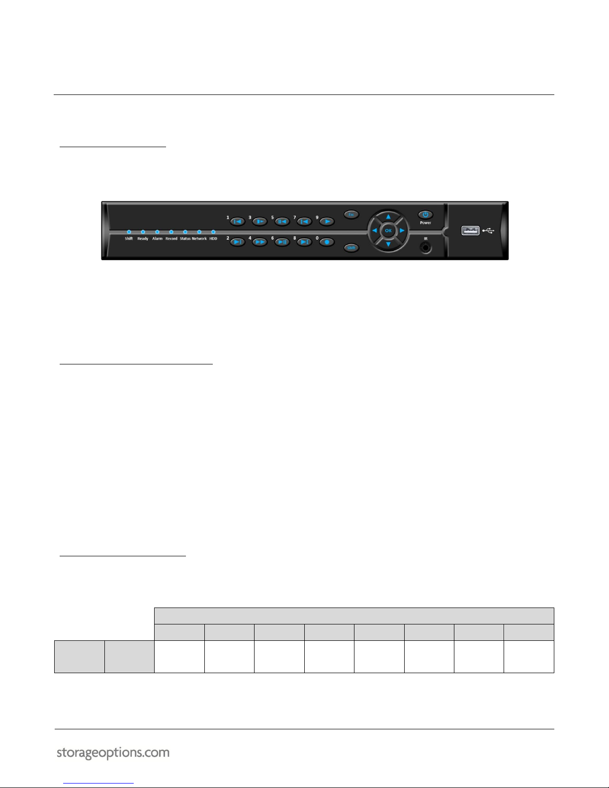
6.1 – FRONT PANEL
LED INDICATORS: Shows status of HDD activity, recording, alarm, network and power.
PLAYBACK CONTROLS: Press buttons 1-8 to view the selected channel in full-screen.
BUTTON
PRIMARY FUNCTION (SHIFT OFF)
SECONDARY FUNCTION (SHIFT ON)
1
Skip back to previous file
-
2
Skip forward to next file
-
3
Slow playback to 1/2, 1/4, 1/8 or 1/16 speed
-
4
Fast forward playback to 2x, 4x, 6x or 8x
-
5
Play in reverse / pause (toggle)
-
6
Play / pause (toggle)
-
7
Switch to previous camera (Live View mode)
-
8
Switch to next camera (Live View mode)
-
9
-
Opens the Playback Mode menu
0
-
Opens the Record Mode menu
ESCAPE: Closes open menus / cancels changes.
SHIFT: Switches to alternative function for the buttons.
NAVIGATION / OK: Press the arrow buttons to highlight menu options, and OK to confirm selection.
POWER: Press to turn the system on / off (ensure the rear panel ON/OFF switch is in the “on” position).
IR SENSOR: IR receiver for the remote control. Do not cover.
USB SOCKET: Connect a USB flash drive here for video file backup.

13
6.2 – REAR PANEL
Refer to the diagram and table below for information on the DVR’s various connections.
REFERENCE
PHYSICAL CONNECTOR
DESCRIPTION
1
Audio input
Connect audio input (phono)
2
Alarm port
Connects to an alarm system. For advanced
users and system installers only. Not supported
by Storage Options.
3
Video input
8x numbered video inputs for cameras (BNC)
4
VGA output
Connect to a monitor with VGA (D-Sub) input
5
Video output
Connect to a TV or monitor (BNC)
6
Audio output
Connect audio output (phono)
7
RJ45
Connect to a computer network
8
USB
Connect a USB mouse
9
RS485
Connect to RS485-compatible PTZ camera
10
POWER input
DC 12V / 3A
To connect a camera via BNC:
1. Align the BNC connector with the notches on the BNC socket and
slide it into place.
2. Rotate the BNC connector clockwise until it locks in place.
To disconnect a camera:
1. Apply pressure to the BNC connector, then rotate anti-clockwise.
2. Slide the BNC connector away from the socket.

14
6.3 – REMOTE CONTROL
The remote control can be used for navigating system menus. When using the remote control, the OK key performs
the same functions as left-clicking the mouse.
To use the remote control with the DVR system:
1. Insert 2x AAA 1.5V alkaline batteries (not included) into the back of the remote control. Please ensure
correct orientation.
2. Refer to the below diagram for button functions:
REF
BUTTON
DESCRIPTION
1
MULT
Switches between 1, 4, 1+7 and 8+info view
modes
2
RECORD MODE
Opens the Record Mode menu
3
SEARCH
Opens the Search menu
4
PLAYBACK CONTROL
Use to play, pause, skip forward / backward,
and fast forward video playback
5
ADDRESS
Not applicable
6
FUNCTION
Displays quick shortcuts to the PTZ Control
and Colour Settings menus
7
NAVIGATION / MENU
Use ↑, ↓, ←, → to highlight menu options
Use OK to confirm selections
8
ESCAPE
Press to close menu windows
9
NUMBERS
In menus, press 0-9 to enter values
In Live View, press 1-8 to view channels in
full-screen display mode
10
-/--
Switch between entering one digit or two

15
6.4 – MOUSE CONTROL
The mouse can be used for navigating system menus.
NOTE
Unless otherwise stated, all system functions described in this manual are achieved through mouse input.
To use a mouse with the DVR system, simply connect the mouse to the lower USB port located on the rear panel.
Left Button:
Click to select a menu option.
During live viewing, double-click on a channel to view in full-screen.
Double-click the channel again to return to split-screen view.
Right Button:
Click to open the Sub Menu.
Scroll Wheel:
In Live View mode, scrolls through individual cameras.
6.5 – USING THE SUB MENU
When using the mouse, open the Sub Menu to access system options, including the Main Menu and PTZ control.
1. Right click anywhere on screen to open the Sub Menu.
2. To close the menu, left-click anywhere on screen (outside the menu).
MAIN MENU:
Opens the system menu
RECORD MODE:
Switch between schedule / manual / stop record modes for all or
individual cameras
PLAYBACK:
Opens PlayBack mode for viewing previously recorded footage
PTZ CONTROL:
Opens the PTZ Control menu (only for use with PTZ cameras, not
supplied)
HIGH SPEED PTZ:
Not applicable
ALARM OUTPUT:
Adjust alarm output settings
COLOUR SETTING:
Opens the Colour Setting menu
OUTPUT ADJUST:
Adjust picture size to compensate for the monitor’s overscan
LOGOUT:
Log the current user out
VIEWS:
Choose the camera view mode from various options

16
POWER ON / OFF
To power the system on, connect the power cable to the DC 12V port on the rear panel. The DVR will automatically
power on.
At start-up, the DVR performs a basic system check and runs an initial loading sequence which includes the colour
bars and “H.264 DVR” images shown below. After a few moments, it will load a live display view.
The system can also be put into standby mode. It will still receive power from the mains socket but will not record
anything until brought back into operation mode.
To put the system in standby, press and hold the power button on the front panel until the on-screen
prompt closes.
To wake the system from standby mode, press and hold the power button on the front panel until the DVR
wakes up.

17
SYSTEM LOGIN
To open the main menu, right-click anywhere on screen to open the Sub Menu, then select MAIN MENU.
Alternatively, press the MENU / EXIT button on the remote control or front panel of the system.
8.1 – PASS CODES
By default, pass codes are disabled on the system. You do not need to enter a pass code when logging in as an
administrator and accessing any menus. For security purposes, it is highly recommended to enable a pass code for
the administrator account via the Password Menu.
NOTE
If pass codes are enabled on the system, you need to select your user name then input your passcode to
log into the system.
8.2 – MENU NAVIGATION
We recommend using the mouse for easiest menu navigation, but it is possible to control many functions using the
remote control or front panel buttons.
Click any option to select it.
If an option requires user input (e.g. alphanumeric characters), an on-screen keyboard or keypad will appear
when that menu is selected. Simply click the characters to input them into the cell.
In Live View mode, right-click anywhere on screen to display a context menu. From here you can access
many function. See section “6.5 – Using The Sub Menu” (page 15) for more information.
Within any mode (except Live View), you can right click anywhere on the screen to display a menu with two
options:
o Up Window: Returns to the previous window
o Show Desktop: Returns directly to the “desktop” (i.e. Live View mode)

18
MAIN MENU
When you enter the Main Menu, you will be presented with six categories which cover all features of the system:
Refer to this table for a description of the main categories:
ITEM
ICON
DESCRIPTION
Record
Use this menu to configure recording schedules, video playback, and backup settings.
Alarm
Configure motion detection, video blind, video loss, alarm input and output, and system
abnormalities.
System
Use this menu to configure system date and time, encoder settings, network connectivity,
network services, GUI adjustments and PTZ.
Advanced
Contains options for HDD management, user account configuration, video output
adjustment, maintenance, and device information.
Info
Shows system information.
Logout
Choose to log the current user out, shutdown or reboot the system.
The following sections of this manual will guide you through the most commonly used features of this DVR:
Setting the system time
Formatting the Hard Disk Drive (HDD)
Configuring recording settings
Motion detection recording
File backup
Network connectivity
19
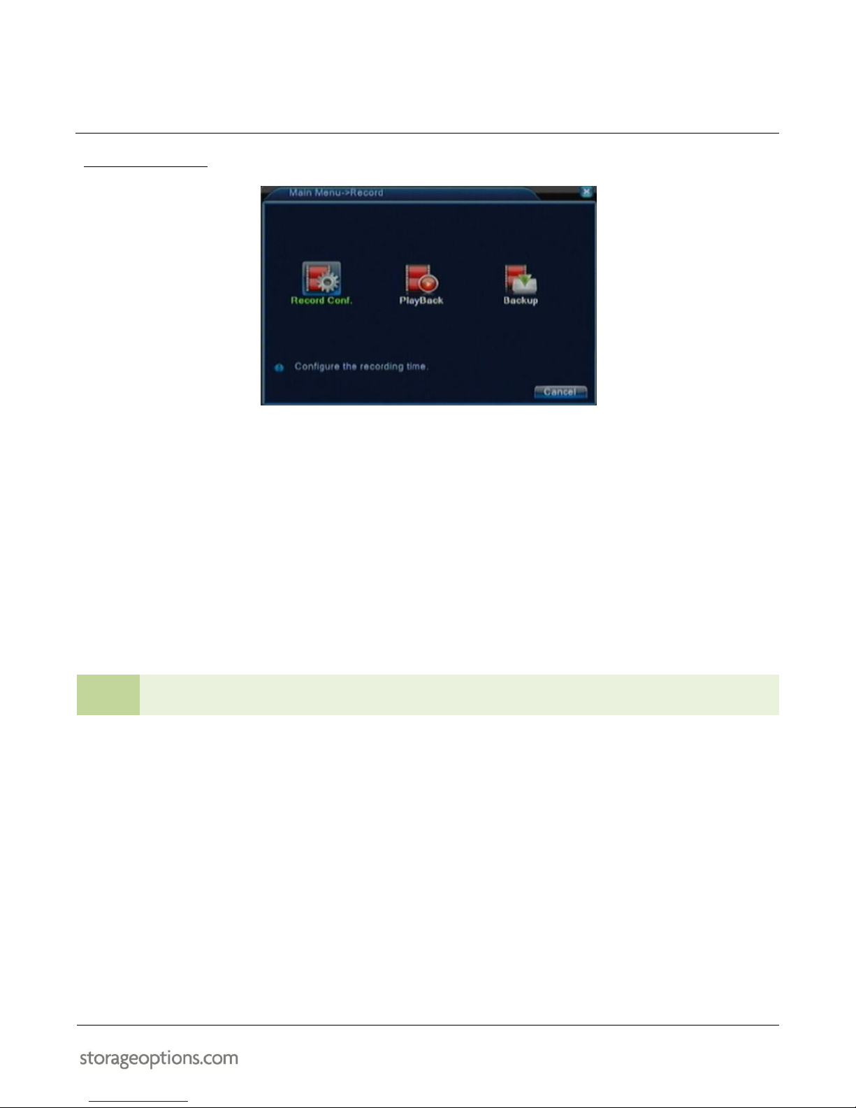
9.1 – RECORD MENU
Record Configuration:
Configure schedules for up to four different time periods, set up manual recording, enable motion detected
recording, or stop recording for a specific channel or all channels.
Playback:
Search the recording archive for specific footage, and use filters to refine search results. Play back the
recording of one or multiple cameras.
See section “Playback Mode” (page 30) for more information.
Backup:
Search the recording archive for specific footage, and use filters to refine search results. Copy specific files
to USB flash memory for backup purposes. Copy encrypted H264 files or decrypt to standard AVI files.
See section “File Backup” on (page 31) for more information.
TIP
From any sub menu, you can click “Advanced” then “Up Window” to return to the previous menu.

20
9.2 – ALARM MENU
Motion Detect:
Configure motion detection settings including sensitivity, detection region, schedule, detection delay, alarm
output, record triggering, on-screen messages, e-mail and FTP triggering.
See section “Motion Detection Recording” (page 29) for more information.
Video Blind:
For advanced users only. Not supported by Storage Options.
Video Loss:
For advanced users only. Not supported by Storage Options.
Alarm Input:
Only for use when connecting to a building alarm system. Not supported by Storage Options.
Alarm Output:
Only for use when connecting to a building alarm system. Not supported by Storage Options.
Abnormality:
Set up a message or buzzer notification in the event of a problem such as no HDD, HDD error, or HDD full.
TIP
From any sub menu, you can click “Advanced” then “Up Window” to return to the previous menu.

21
9.3 – SYSTEM MENU
General:
Set system date and time, including display format, choose your preferred language, what the system should
do once the HDD is full, video output standard, delay before automatic logout of a dormant user, etc.
Encode:
Configure quality settings for both the main and extra video streams for each camera, including compression
type, frame rate, bit rate (variable or constant), etc.
Network:
Configure network accessibility for the DVR. Choose from auto-assigned (DHCP) addressing, or supply static
address information manually.
Network Service:
Configure settings for direct Internet (PPPoE) connection, e-mail, FTP server, mobile port number, and
Universal Plug ‘n’ Play (UPnP).
GUI Display:
Rename video channels, choose which information should be displayed, enable menu translucency, change
VGA output resolution, etc.
PTZ Configuration:
Only for use with PTZ cameras (not supplied). Configure protocol, address, baud rate and parity.
RS232:
For advanced users only.
Tour:
Only for use with PTZ cameras (not supplied). For advanced users only.
TIP
From any sub menu, you can click “Advanced” then “Up Window” to return to the previous menu.
22
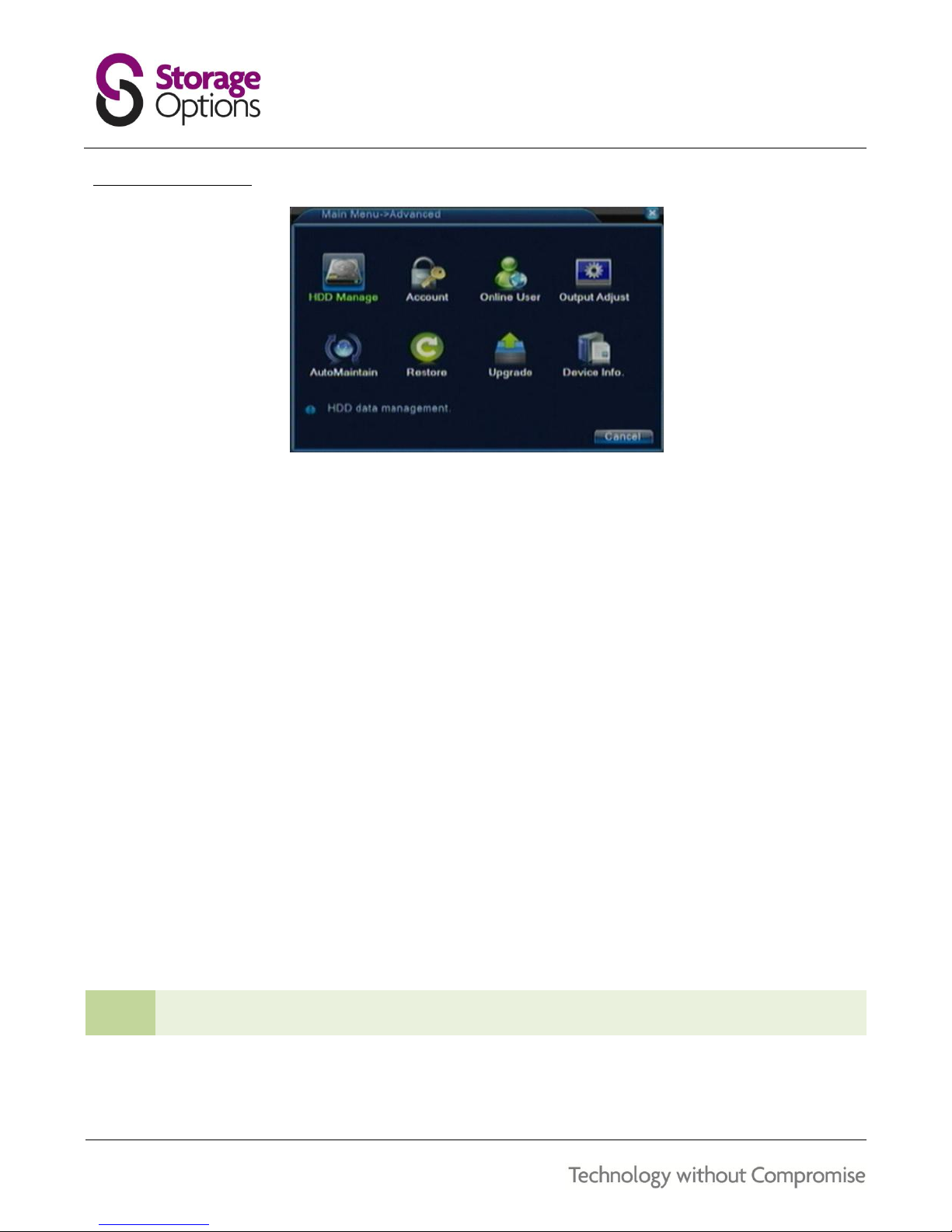
9.4 – ADVANCED MENU
HDD Management:
Configure HDD options including read / write permissions, formatting and partitioning.
See section “Format The Hard Disk Drive” (page 26) for more information.
Account:
Add, modify and delete users and user groups.
Online User:
View a list of which users are currently logged in via the network and choose to disconnect them.
Output Adjustment:
Adjust image overscan for all four sides of the video output, to stop the monitor / TV cropping the edges.
Auto Maintenance:
Configure a schedule for the DVR to automatically reboot, and to automatically delete old video files.
Restore:
Choose individual or all settings to reset back to defaults.
Upgrade:
Use this option to upgrade to a newer version of the system firmware.
Device Info:
Displays information on number of audio channels, number of alarm channels, graphical user interface (GUI)
theme, remote control type, etc.
TIP
From any sub menu, you can click “Advanced” then “Up Window” to return to the previous menu.
23
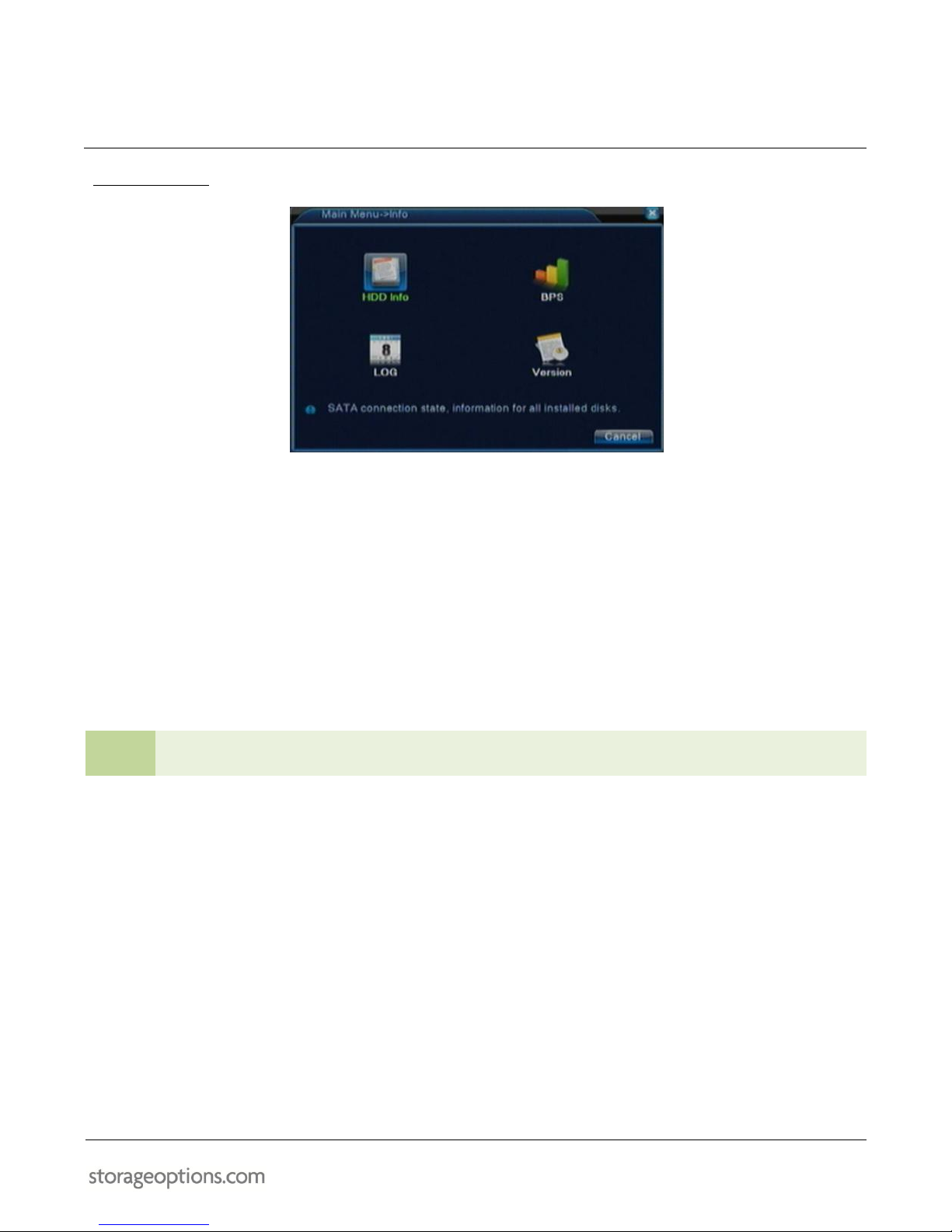
9.5 – INFO MENU
HDD Information:
Displays information on total capacity, remaining capacity and HDD status.
BPS:
Displays current bit rate values in real time for each camera and how much capacity (approximately) each
will use per hour.
Log:
Displays a list of event information, such as system restarts, errors, account login / logout, etc.
Version:
Displays version information for the system, the unit build date and serial number.
TIP
From any sub menu, you can click “Advanced” then “Up Window” to return to the previous menu.
24
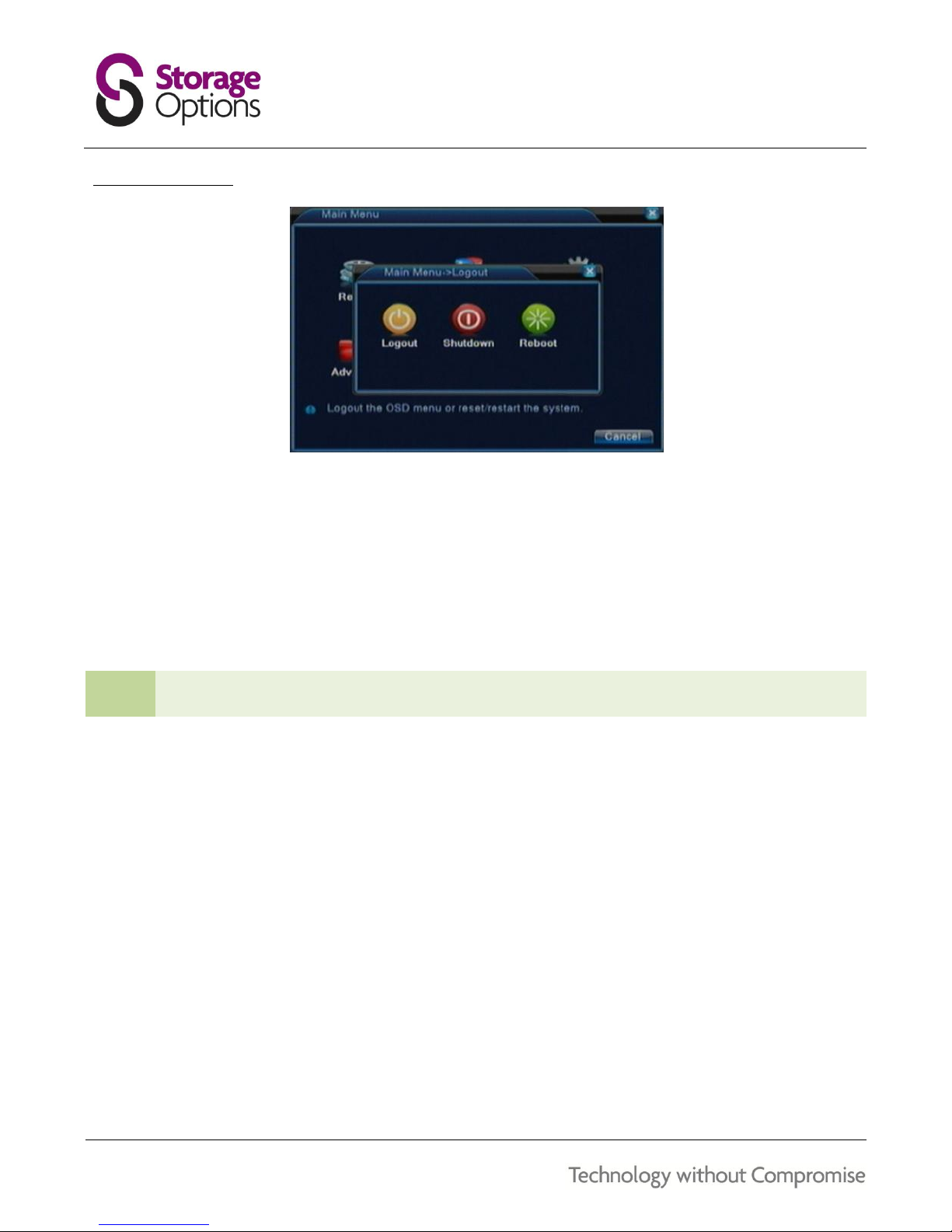
9.6 – LOGOUT MENU
Logout:
Log out the current user. Another user can then log in. Only one user can log into the system at a time.
Shutdown:
Shuts the system down completely.
Reboot:
Shuts the system down then immediately restarts it. Useful when changed settings require the system to
restart before they take effect.
TIP
From any sub menu, you can click “Advanced” then “Up Window” to return to the previous menu.
25
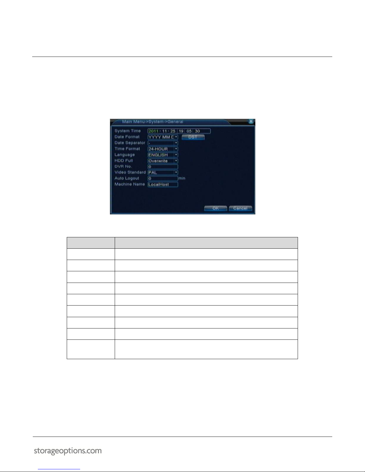
SET SYSTEM DATE & TIME
Before setting any recording schedules, the system clock should be configured, to ensure accuracy of time and date
information printed onto recorded events.
Go to Main Menu System General to change the date and time settings.
Here you can set the system date and time, change the date format, and time format (12H or 24H).
MENU ITEM
DESCRIPTION
System Time
Set the system date
Date Format
Choose the date display format
Date Separator
Choose whether to separate dates with “/”, “.” or “-”
Time Format
Choose 12 or 24 hour clock format
Language
Select your language from this list
HDD Full
Choose what the DVR should do when the HDD becomes full
DVR No.
If you have multiple DVRs, you can number them here
Video Standard
Choose PAL for UK, NTSC for America
Auto Logout
Choose the length of time before the system automatically logs out
the current user

26
FORMAT THE HARD DISK DRIVE
This DVR uses a Hard Disk Drive (HDD) to record and store video footage. You must format the HDD before it can be
used to record video.
To format the HDD:
1. Go to Main Menu Advanced HDD Manage.
2. Select the HDD from the list (there will only be one drive listed, as per the below screenshot), then click
“Format Disk”. Click “OK” on the message box to format the HDD.
3. A message will appear at the bottom of the window to indicate formatting is in progress. After a short
period of time, “Format has finished!” will appear on screen.
4. Click “OK” to close the window. You can then close the “HDD Manage” window.
After formatting is complete, you can start recording on the HDD.
NOTE
It is also possible to partition the HDD into two separate logical drives. This is an advanced function and
should only be performed by experienced users.

27
CONFIGURE RECORDING SETTINGS
Before you can start using your DVR to record surveillance footage, you need to configure various recording settings.
There are two separate menus which are used to configure camera settings:
Record Configuration
Encode Settings
12.1 – RECORD CONFIGURATION
Go to Main Menu Record Record Configuration to adjust these settings.
Choose an individual channel (camera) to edit settings for, or select “All” to configure the same settings for
all cameras.
You can adjust the length of recorded files (in minutes).
If motion is detected, recording will start a few seconds before the motion event, according to the value
defined in the PreRecord cell.
Each camera can be configured to record on a schedule, manually, or if an alarm is triggered.
If scheduled recording mode is enabled, the options underneath will become available and you can choose
how the scheduled recording takes place over up to four time periods per day:
o Regular recording takes place continuously.
o Detect recording only occurs when motion is detected on the camera.
o Alarm recording only occurs when an alarm is triggered.
For example, you could set:
o Period 1 from 00:00 to 08:00 as motion detected recording
o Period 2 from 08:00 to 18:00 as regular (constant) recording
o Period 3 from 18:00 to 20:00 as motion detected recording
o Period 4 from 00:00 to 24:00 as alarm-triggered recording

28
12.2 – ENCODING OPTIONS
Go to Main Menu System Encode to adjust these settings.
Choose an individual channel (camera) to edit settings for, or select “All” to configure the same settings for
all cameras.
There are two video streams available for each camera, and both can be configured separately.
o The main stream allows a choice of D1 and HD1 resolution for the first two cameras only.
o For all 8 cameras, you can choose CIF or QCIF resolutions.
o The extra stream only allows a choice of CIF and QCIF resolutions.
o The extra stream is designed for low-bandwidth connectivity, e.g. when connecting to the DVR over
the Internet.
The higher the frame rate, the smoother recorded footage will be, but file sizes will be significantly larger.
You can choose between Variable Bit Rate (VBR) or Constant Bit Rate (CBR) recording modes.
o When VBR is selected, you can choose overall quality.
o When CBR is selected, you can choose the actual bit rate that will be used.
A higher number of I frames (i.e. smaller interval) will result in more accurate and higher quality video
recording but it will also increase the HDD capacity needed.
o Choose a low value for cameras which are viewing high-traffic scenes
o Choose a high value for cameras which are viewing low-traffic scenes
Only the first four cameras can utilise audio.
o On the main stream you can choose to switch only the audio on / off.
o On the extra stream, you can choose to switch both video and audio on /off.

29
MOTION DETECTION RECORDING
The motion function can trigger recordings to take place whenever movement is detected by the DVR.
To set up 24-hour motion detection recording on all connected cameras:
1. Go to Main Menu Record Record Conf.
2. Set “Channel” to “All”, “Mode” to “Schedule” and “Week” to “All”.
3. Set “Period 1” to “00:00 – 24:00” and make sure the corresponding “Detect” checkbox is ticked.
4. Click “OK” to save these settings.
5. Next, go to Main Menu Alarm Motion Detect.
6. Set “Channel” to “All” and make sure the “Enable” checkbox is ticked, then choose an appropriate sensitivity
level.
7. Next to “Region”, click “Set”, then mark the screen in red where you would like motion to be monitored. By
default, the whole viewport will be red.
8. Next to “Period”, click “Set”, choose “All”, then tick the checkbox on the first “00:00 – 24:00”. The table
underneath will fill green to indicate motion detection is activated for 24/7 use.
9. Return to the previous menu, then click “OK” to save these settings.

30
PLAYBACK MODE
Playback mode allows you to review previously recorded footage. It also allows you to back up important recordings
(for example a break-in / suspicious activity) to a USB flash device.
To access Playback mode:
Go to Main Menu Record Playback.
OR
1. From the main live (grid) view, right-click anywhere on screen to open the context menu.
2. From the list of options, select Playback.
To use Playback mode:
1. Click the Search button on the bottom right of the screen:
2. Choose your search conditions from the available options, then click “Search” to find recordings.
3. A list of recordings will show on the right of the screen. Double-click a recording to show all applicable
cameras (as selected in the Search Condition window previously).
4. Use the controls along the bottom of the screen to fast-forward, skip between recordings, pause, and play in
slow-motion.
You can double-click on a video window to display it in single camera view mode.
Double-click again to return to the 3 x 3 grid view.
Skip Decode
Prioritises decoding of channels 1 & 2. Channels 3-8 may skip frames when playing back.
Average Decode
Decoding performance will be the same across all 8 channels. Playback synchronisation is
prioritised so frames may be dropped to keep all cameras in sync.
Full Decode
Prioritises real time playback at the expense of slowing down the encoding process.

31
FILE BACKUP
Recordings made on the DVR can be copied from the internal Hard Disk Drive (HDD) to a USB flash drive connected
to the front panel USB port.
1. Connect your USB flash drive to the USB socket. It will only fit one way, so do not force it. Doing so could
damage your USB flash drive or the USB socket.
2. Go to Main Menu Record Backup to open the Backup facility.
3. Select “Detect” to search for your USB flash drive. Your flash drive will be listed. Ensure there is a tick in the
box next to its name, and select “Backup” to continue.

32
4. The Backup window allows you to list files recorded between specific start and end dates. Adjust these
dates and times to suit the situation. You can also choose to list recordings only of a specific type (e.g. all,
normal, alarm, etc) and select which channels (cameras) you want to back up.
5. Your files will be listed in the table. Check the box next to each one you wish to copy to the USB flash drive.
TIP
Required capacity for the selected recordings will be displayed underneath the table, along with the
remaining capacity on the USB flash drive. This can help you determine how many files you can store on
the USB flash drive.
6. Select either H264 or AVI for the backup format, then select “Start”.
H264 copies the raw encrypted video files to USB flash. This is the quickest backup method.
AVI decrypts and converts the encrypted files into a format which is playable on most Windows
computers using video playback software. This method takes approximately twice as much time.
NOTE
For playback of AVI files, we recommend VideoLAN VLC Media player. This free software can be
downloaded from http://www.videolan.org/ and is available for Windows, Linux and Mac OSX.
7. Wait for the DVR to copy the files to the USB flash drive. This can take a long time depending on chosen
options and speed of the USB flash drive. Once it has finished, a message will be displayed on screen. You
can then close the Backup window and remove the USB device.
33
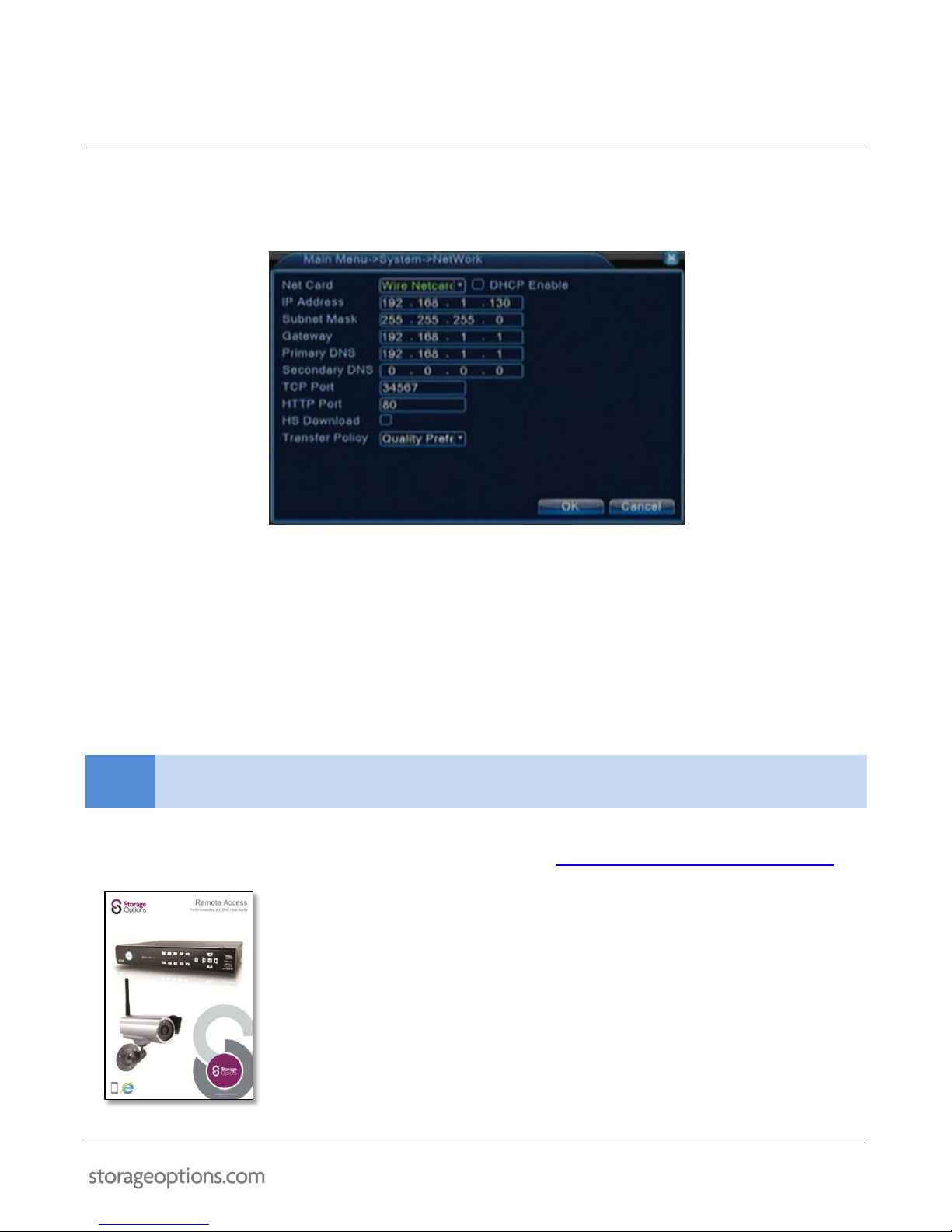
NETWORK SETTINGS
Before being able to access the DVR over a network, you need to make sure the network settings are correctly
configured.
* The above screenshot is only an example of valid network settings. Do not simply copy them onto your DVR as your network may differ.
To configure network settings:
1. Connect the DVR to your Internet router using a standard network cable with RJ45 connector.
2. Leave “Net Card” at the default setting.
3. Tick the “DHCP Enable” checkbox to allow your router to assign address information automatically, then click
“OK” to accept the changes. You will need to restart your DVR system before the changes take effect.
NOTE
Alternatively, if you would like to view your DVR remotely (i.e. outside your local network, over the
Internet) you will need to un-tick “DHCP Enable” and supply static address information manually.
For detailed help with configuring network access on your DVR, we recommend you follow the “Storage Options
Remote Access Guide”, which is available as a downloadable PDF from http://www.storageoptions.com/support/.
The guide covers the network setup and port forwarding process, including in-depth
instructions on the following:
Connecting equipment
Finding your router’s LAN and Internet IP addresses
Setting up your Storage Options system
Using the Ping tool to test configuration
Viewing your device in Internet Explorer
Configuring port forwarding
Configuring mobile devices (e.g. mobile phone)
Static / dynamic WAN IP addresses and configuring a DDNS account

34
NETWORK CONNECTIVITY
The DVR features built-in browser based software which allows access to the system locally over the Local Area
Network (LAN) or remotely over the Internet, using Internet Explorer.
Before attempting to use the network functionality of your DVR, we recommend you follow the “Storage Options
Remote Access Guide”, which will help you configure your DVR correctly for network use. The guide is available as a
downloadable PDF from http://www.storageoptions.com/support/.
Once you have correctly configured the network settings for your DVR, access it via your web browser. Open
Internet Explorer and type the DVR’s IP address into the address bar, then press Enter to load the page.
On first use, you will be prompted to install ActiveX controls. Please follow on-screen instructions and if you are
given the option to block or allow any controls, please allow them otherwise you will not be able to access your DVR.
To ensure stable use of the network surveillance functionality, it is recommended to only use the following operating
systems and browsers:
SUPPORTED OPERATING SYSTEMS
RECOMMENDED WEB BROWSERS
Windows XP
Internet Explorer 6
Windows Vista
Internet Explorer 7
Windows 7
Internet Explorer 9

35
17.1 – USING THE NET SURVEILLANCE INTERFACE
With your DVR connected to your Local Area Network (LAN), you can log in to the system using Internet Explorer
browser.
NOTE
The DVR must be connected to your local or wide area network before attempting remote access.
To log into the system:
1. Open Internet Explorer. In the address bar, enter the IP address of the DVR (e.g. http://192.168.1.10). If you
have configured an HTTP / Web port other than the default of 80, you will need to append that port number
to the address (e.g. http://192.168.1.10:80).
2. You must install the ActiveX control in order to access the DVR. Click the yellow attention bar at the top of
the main page and select “Install ActiveX Control” or “Run Add-on”.
3. In the warning box, click “Install” or “Run” to allow installation of the ActiveX control. Once it has installed
you may need to refresh the page or restart Internet Explorer. The login page should appear:
4. Type “admin” for the User Name. Leave the password field blank (default).
NOTE
If you have enabled passwords on the DVR, enter the USER or ADMIN password. However, only the
ADMIN can change settings and options on the system.
5. Click the “Login” button to access the surveillance system.
36
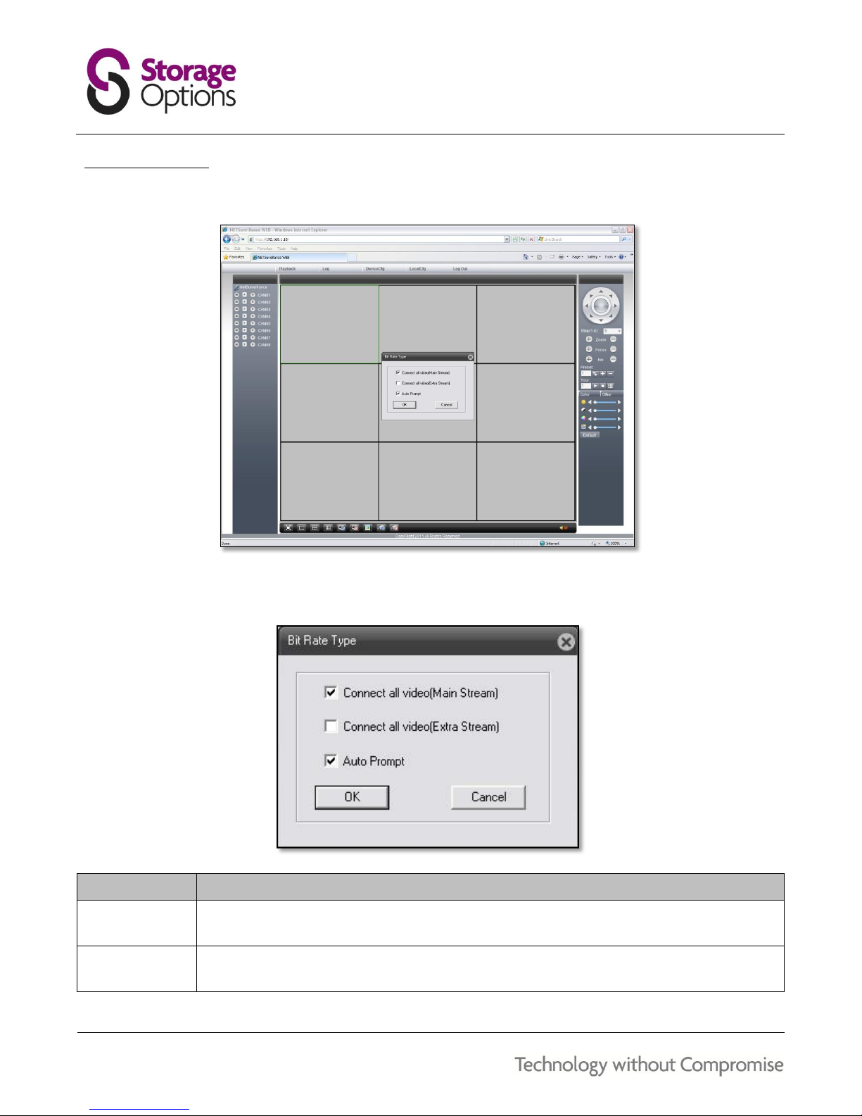
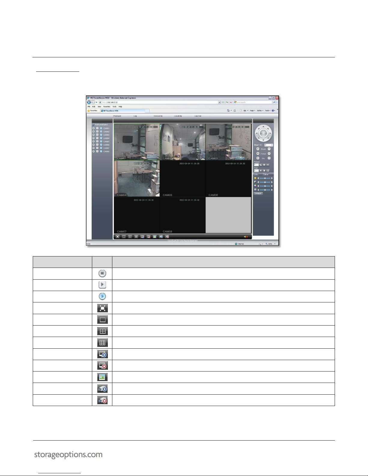
17.2 – MAIN SCREEN
Once you have logged in, the Remote Surveillance main screen appears in the browser.
The “Bit Rate Type” window will appear in the middle of the screen. Make your choice from the available video
stream types (see table below), then click the “OK” button to continue.
ITEM
DESCRIPTION
Main Stream
Connects to a high-bandwidth main video stream of each camera, using highest quality settings.
Preferred when connecting over a Local Area Network (LAN) connection.
Extra Stream
Connects to a low-bandwidth video stream of each camera, using lower quality settings.
Preferred when connecting over an Internet Wide Area Network (WAN) connection.
37
17.3 – LIVE VIEW
By default, the browser-based network surveillance system opens in Live View mode (split-screen).
ITEM
ICON
DESCRIPTION
Local Record
Starts / stops recording of the corresponding video channel to the computer’s HDD.
Extra Stream
Switches to the low-bandwidth video stream for the corresponding channel.
Main Stream
Switches to the high-bandwidth video stream for the corresponding channel.
View Full Screen
Displays the program in full screen mode. Press the “Esc” key to exit.
View 1
View the currently selected camera by itself.
View 4
View four cameras in split-screen grid mode.
View 9
View all eight cameras in split-screen grid mode (default view).
Connect All Video
Connects to all video streams.
Disconnect All Video
Disconnects from all video streams.
Snapshot
Takes a snapshot image of the currently selected camera feed.
All Channel Record
Starts recording of all video channels to the computer’s HDD.
Close All Record
Stops recording of all video channels.
38
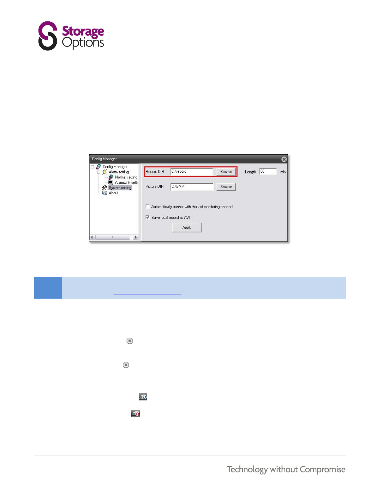
17.4 – RECORDING
You can record video directly to your PC using the remote surveillance software. First, you will need to specify
where you would like recorded files to be saved:
1. Select “LocalCfg” from the menu at the top of the screen. The “Config Manager” window will appear on
screen. Choose “System Setting” from the menu on the left.
2. Click “Browse” to choose a suitable video recording folder. The current user account logged into Windows
will need to have permission to write to the chosen folder. Videos are saved to C:\record\ by default.
3. It is advisable to enable the “Save local record as AVI” option by checking the box. If this box is not checked,
the resulting recordings will be encrypted and you will not be able to play them in media playback software.
NOTE
For playback of AVI files, we recommend VideoLAN VLC Media player. This free software can be
downloaded from http://www.videolan.org/ and is available for Windows, Linux and Mac OSX.
4. Click “Apply” to save the setting.
To record video to your PC:
Click the “Local Record” icon next to the corresponding video channel to record that channel to the
computer’s HDD.
Click the “Local Record” icon again to stop recording.
OR
Click the “All Channel Record” icon to record all currently connected video streams.
Click the “Close All Record” icon to stop all recordings.

39
17.5 – SCREEN CAPTURE
You can use the remote surveillance software to take a snapshot of the selected video channel on the main display
screen. First, you will need to specify where you would like the images to be saved:
1. Select “LocalCfg” from the menu at the top of the screen. The “Config Manager” window will appear on
screen. Choose “System Setting” from the menu on the left.
2. Click “Browse” to choose a suitable picture folder. The current user account logged into Windows will need
to have permission to write to the chosen folder. Pictures are saved to C:\BMP\ by default.
3. Click “Apply” to save the setting.
NOTE
To view still images, you can use any image viewing software that supports BMP files, such as Windows
Photo Viewer or Paint. Simply double-click the file to open it.
You can use the remote surveillance software to take a snapshot of the channels on the main display screen. Screen
captures can be useful for your own records, or may be needed by authorities in case of a security incident.
To take a screen capture:
1. Select the channel you want to capture. The selected channel will be highlighted in a yellow frame.
2. Click the “Capture” icon to take a screenshot. Captured images are saved to C:\BMP\ by default.
40
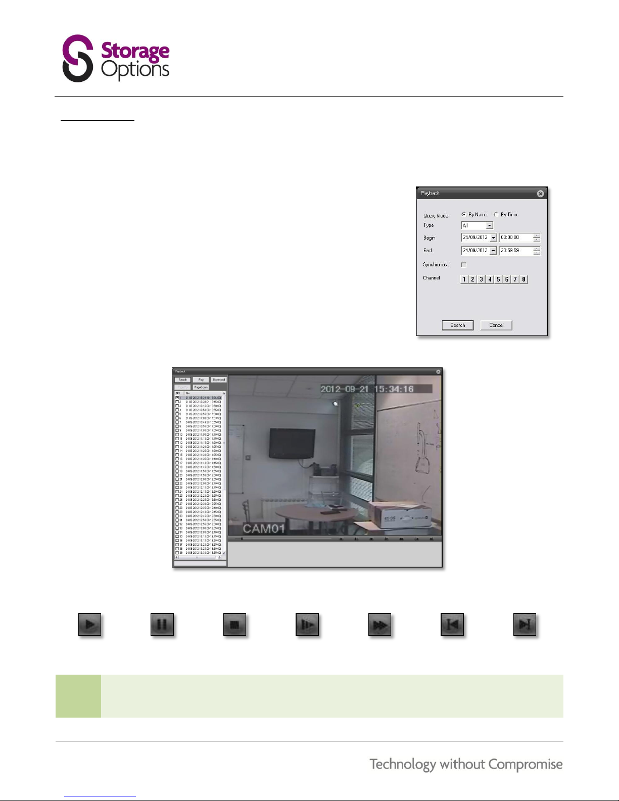
17.6 – PLAYBACK
Use the Replay menu to search and play back video that has been previously recorded on the DVR’s internal HDD.
To use the playback menu:
1. Click “Playback” at the top of the main screen. The “Playback” menu
will be displayed.
2. Choose an event type, and then enter begin and end times to narrow
down your search.
3. Click a channel number, then click “Search” to display search results for
your criteria.
4. The results of your search will be listed in a column on the left. Click to
select a recording, then click “Play” to view the video in the right-hand
pane.
5. Use the transport controls below the video to control playback:
Play
Pause
Stop
Slow Motion
Fast Forward
Skip Back
Skip Forward
TIP
After selecting a recording on the list, you can click “Download” to copy it from the DVR to the computer’s
HDD. Files copied to the computer will be encrypted. You will need to use the Player software included
on the software CD to play these encrypted files.

41
17.7 – PTZ CONTROL
You must have a PTZ camera (not included) connected to the system in order to use the pan, tilt and zoom controls.
To control a PTZ camera:
1. Select the channel of the connected PTZ camera.
2. Click the ← or → navigation arrows to pan, and ↑ or ↓ keys to tilt the camera.
3. Click + / - to adjust zoom, focus, and iris values.
Preset:
Use this function to add and recall preset positions for the camera to point to.
Tour:
Use this function to make the camera automatically move to each preset position in a chain.
17.8 – REMOTE DVR SETUP
The DVR’s settings can be configured through Internet Explorer, as well as through it’s own menu system. This can
be useful if you quickly need to reconfigure a setting and do not have physical access to the DVR.
Choose “DeviceCfg” on the top menu to open the “Device Config” window.
When you enter the Main Menu, you will be presented with five categories which cover all features of the system, in
the same manner as on the DVR itself:
ITEM
ICON
DESCRIPTION
Record
Use this menu to configure recording schedules, video playback, and backup settings.
Alarm
Configure motion detection, video blind, video loss, alarm input and output, and system
abnormalities.
System
Use this menu to configure system date and time, encoder settings, network connectivity,
network services, GUI adjustments and PTZ.
Advanced
Contains options for HDD management, user account configuration, video output
adjustment, maintenance, and device information.
Info
Shows system information.
CAUTION
If a user is logged into the DVR’s own interface, you will not be able to reconfigure any settings using
the web-based interface until they have logged out.

42
REMOTE ACCESS
To access this product from a remote location (i.e. outside your current network), your Internet router will need to
have port forwarding rules in place. This will allow traffic from the Internet to pass through the router’s firewall and
to your Storage Options system. The default ports for this product are listed here:
PROTOCOL
PORT / PORT RANGE
TYPE
HTTP (Web)
80 (see tip below)
TCP
Media
34567
TCP
Mobile
34599
TCP
TIP
Port 80 is used by default on your local network for ease of access. For more secure remote access, we
recommend changing port 80 on your device to a different number (such as 81 or 82), then creating the
port forwarding rule to match.
To correctly configure remote access to your new product, we recommend you follow the “Storage Options Remote
Access Guide”, which is available as a downloadable PDF from http://www.storageoptions.com/support/.
The guide covers the network setup and port forwarding process, including in-depth
instructions on the following:
Connecting equipment
Finding your router’s LAN and Internet IP addresses
Setting up your Storage Options system
Using the Ping tool to test configuration
Viewing your device in Internet Explorer
Configuring port forwarding
Configuring mobile devices (e.g. mobile phone)
Static / dynamic WAN IP addresses and configuring a DDNS account
We also recommend you take a look at http://www.portforward.com. This website is a very useful resource for full
step-by-step port forwarding guides that cover the vast majority of available routers.
NOTE
It is not possible to cover the huge amount of routers, and how to set up port forwarding on each, in this
manual. Remote access is an advanced networking practice. If you are unsure how to set up port
forwarding on your router, consult its instruction manual or contact your Internet Service Provider.

43
HARD DISK DRIVE INSTALLATION
If you wish to replace the pre-installed HDD with a higher capacity drive, follow these instructions. If you are at all
hesitant to perform the following procedure, please refer to qualified service personnel.
Follow these steps to install a HDD:
CAUTION
When working with electrostatic sensitive devices such as a Hard Disk Drive (HDD) or DVR unit, make
sure you use a static-free workstation. Any electrostatic energy coming in contact with the hard disk
or DVR can damage it permanently.
1. Remove the 4 screws (2 each side) which hold the cover in place, then slide it off. With the front panel
facing you, the HDD mounts to the left of the chassis. There are 4 screw holes to mount the HDD.
2. Align the HDD with the mount points (circled in red above) and secure in place using 4 screws (provided)
through the underside of the chassis.
3. Connect the SATA and POWER cables to the HDD.
CAUTION
SATA and POWER cables are designed to fit only one way. Do not force them into place or you may
damage the HDD.
4. Replace the cover and secure it in place using the 4 screws removed in step 1.
5. You must format (prepare) the HDD before it can be used for recording.

44
TROUBLESHOOTING
If a solution to your problem is not listed below, please call our technical support team (see below).
PROBLEM
POSSIBLE CAUSES
SOLUTIONS
System is not receiving power, or
is not powering up.
Cable from power adapter is loose or
unplugged.
Confirm that all cables are connected correctly.
Confirm that the power adapter is securely connected to the
back of the unit.
Cables are connected but system is not
receiving sufficient power.
Confirm the system is powered on (LED indicators on front
panel should be on)
If the DVR is connected through a power bar or surge protector,
try bypassing it and connecting power directly from the mains
socket to the DVR.
Confirm that there is power at the outlet.
Remote control is not detected by
the system.
Batteries in the remote control are
drained.
Install 2x fresh AAA 1.5V alkaline batteries in the remote
control. Ensure correct orientation.
There are no batteries in the remote
control.
Hard Disk Drive (HDD) is not
detected by the system.
HDD cables are loose or not connected
properly.
Remove the housing and check that the cables are firmly
connected.
There is no HDD in the system.
Open the housing and install a 3.5” SATA HDD (up to 2TB).
HDD is full and the unit is no
longer recording
Overwrite mode is not enabled.
Check configuration in Main Menu System General.
Mouse not detected by the
system.
Mouse cable not firmly connected to
the system.
Firmly connect the mouse cable to the USB port on the rear
panel of the DVR.
Mouse is not connected to the system.
System needs to be reset.
Power off the system (disconnect power cable). Firmly connect
a USB mouse to the USB port on the rear panel of the DVR.
Reconnect the power cable to the DC 12V port.
There is no picture on selected
channels / camera picture is not
being displayed.
Camera cables are loose or have been
disconnected.
Check the camera video cable and connections.
Disconnect and reconnect the cable at both the system and
camera ends.
Reconnect the camera to another channel or use another cable.
There is no sound from attached
cameras.
Audio cables are loose or have been
disconnected.
Check the audio connections to the DVR.
Audio channels are disabled in the
system menu.
Check configuration in Main Menu System Encode.
Volume on external speakers (not
included) is low / muted / off.
Increase volume on external speakers (not included).
A “whirring” noise is coming from
the system.
Fan is active.
This is normal – the exhaust fan is working.
The system beeps at start up.
This is normal.
The system beeps during motion
detection.
Motion detection is enabled and the
alarm buzzer is activated.
Check configuration in Main Menu Alarm Alarm Input.
WARRANTY AND TECHNICAL SUPPORT
storageoptions.com/support/
support@storageoptions.com

45
PRODUCT SPECIFICATION
DIY Home CCTV Kit Plus
Video Compression:
H.264
Audio Compression:
ADPCM
Video Input:
8 channel (BNC)
Video Output:
1 channel (BNC)
Audio Input:
4 channel (phono)
Audio Output:
1 channel (phono)
Resolution:
PAL: QCIF 176 x 144, CIF 352 x 288, HD1 704 x 288, D1 704 x 576
NTSC: QCIF 176 x 120, CIF 352 x 240, HD1 704 x 240, D1 704 x 480
Video Frame Rate:
PAL: 25fps
NTSC: 30fps
VGA Interface:
1 channel (D-Sub)
VGA Resolution Support:
800 x 600, 1024 x 768, 1280 x 1024, 1366 x 768, 1440 x 900
Alarm Input:
4 inputs
Alarm Output:
1 output
Network:
Ethernet (10/100Mbps)
Monitoring Methods:
Internet, mobile phone, e-mail
Control:
Mouse, Remote control, DVR control
Backup:
USB and Network
HDD:
1 bay, up to 2TB
Security Feature:
Password protection, multiple user accounts
Power Supply:
DC 12V input
Operating Temperature:
-10 to 50oC approx
Humidity:
< 90%
Device Dimensions:
310 x 215 x 45mm (W x D x H)
Weight:
Net: 1.9KG; Gross: 2.9KG

46
WARRANTY AND PRODUCT SUPPORT
If you are experiencing difficulties with your product, or have questions which are not answered in this instruction
manual, our dedicated support site offers a wide range of clearly written FAQs, manuals and user guides which are
designed to help you get the most from your purchase.
Visit our dedicated support site at storageoptions.com/support/ for FAQs, manuals and user guides
If you are unable to find an answer online, still experiencing issues or suspect your product to be faulty, our UK
based customer service team is available to offer full support, and can be contacted via the support pages of our
website.
Submit a service request online if you cannot find an answer to your problem
A member of our UK based support team will review your case and offer the highest level of advice and
support
If our team believes that the product in question is faulty, we will issue a returns authorisation and arrange for a
replacement to be sent free of charge.*
Return the product free of charge* – a pre-paid shipping label will be issued to return the product
Within 5 to 10 days a replacement product will be sent at no charge to you
Replacement product delivered directly to you
Please contact us directly if you have any queries or concerns:
storageoptions.com/support/
support@storageoptions.com
Our aim is to provide the best possible service to our customers. We have a wealth of support material, guides and
FAQs available on our website to help you get the most from your product. Our dedicated UK based Customer
Service team are also on hand to offer further support and, in the unlikely event of any fault developing with your
purchase, we have a full returns procedure designed to make receiving a replacement product as quick and easy as
possible.
*Free replacement service applies to UK Mainland (excluding Scottish Highlands) only. Storage Options reserves the right to charge for delivery to, or collection
from, other locations.

47
NOTES

48
 Loading...