

Page 1
Installation Instructions
2000+ BMW Z8
355mm Front Big Brake
Upgrade
98-139-1470 Rev. B 03-12-03
Page 2
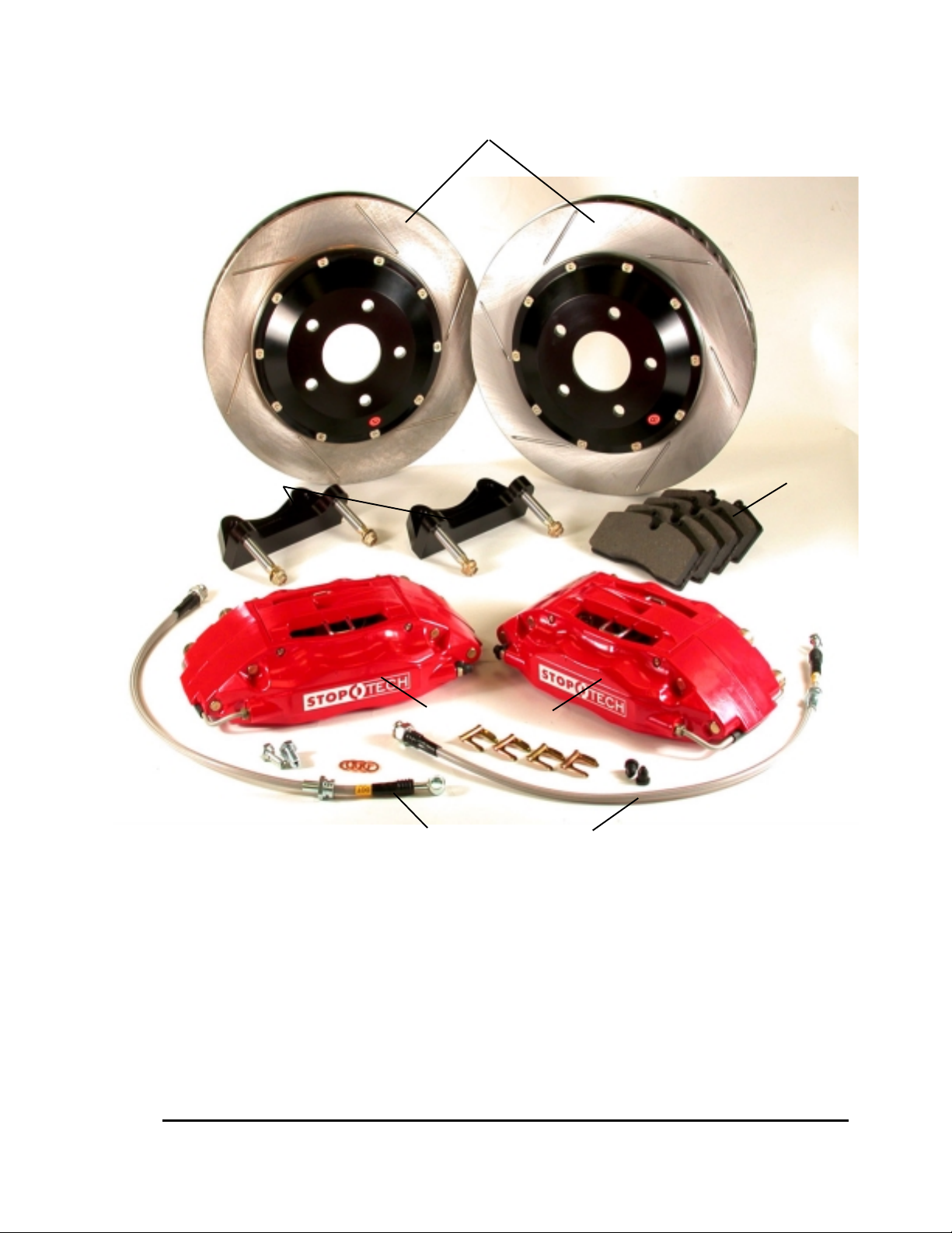
Caliper Brackets
CC
OMPONENT IDENTIFICAOMPONENT IDENTIFICA
C
OMPONENT IDENTIFICA
CC
OMPONENT IDENTIFICAOMPONENT IDENTIFICA
355mm AeroRotor and Hat Assemblies
TIONTION
TION
TIONTION
High Performance Street Pads
ST-40 Calipers
Stainless Braided Lines and Hardware
BMW Z8 Big Brake Kit
This is a representative photograph. The actual components in your kit may appear slightly different.
3541 Unit A, Lomita Boulevard, Torrance, CA 90505 (310) 325-4799
www.stoptech.com 2
Page 3

APPLICAAPPLICA
APPLICA
APPLICAAPPLICA
TION DISCLTION DISCL
TION DISCL
TION DISCLTION DISCL
AMERAMER
AMER
AMERAMER
Caliper Clearance
Most 18” wheels will clear the outer diameter of the caliper on a 355mm kit. However, the more
critical clearance is the gap between the spokes of the wheel and the face of the caliper. Do not
assume a 19, 20 or even 24 inch wheel will clear the face of the caliper.
distance measured from the stock rotor face to the inside of the wheel spokesdistance measured from the stock rotor face to the inside of the wheel spokes
distance measured from the stock rotor face to the inside of the wheel spokes
distance measured from the stock rotor face to the inside of the wheel spokesdistance measured from the stock rotor face to the inside of the wheel spokes
the Z8 Fthe Z8 F
the Z8 F
the Z8 Fthe Z8 F
Drawing page on our website for more specific measurements at www.stoptech.com.
FF
inal fitment of the wheel to the caliper is the rinal fitment of the wheel to the caliper is the r
F
inal fitment of the wheel to the caliper is the r
FF
inal fitment of the wheel to the caliper is the rinal fitment of the wheel to the caliper is the r
rr
ont kit. Wont kit. W
r
ont kit. W
rr
ont kit. Wont kit. W
e re r
ecommend at least 2mm of additional clearecommend at least 2mm of additional clear
e r
ecommend at least 2mm of additional clear
e re r
ecommend at least 2mm of additional clearecommend at least 2mm of additional clear
esponsibility of the customeresponsibility of the customer
esponsibility of the customer
esponsibility of the customeresponsibility of the customer
The actual metal-to-metalThe actual metal-to-metal
The actual metal-to-metal
The actual metal-to-metalThe actual metal-to-metal
is 58.72 mm for is 58.72 mm for
is 58.72 mm for
is 58.72 mm for is 58.72 mm for
ance. ance.
ance. See the Wheel Fitment
ance. ance.
..
.
..
Wheel Spacers
Wheel spacers can provide extra clearance to the outer face of the caliper. This will also space out the
entire wheel, widening the track width of the vehicle. Fender clearances should be checked on
lowered cars, and longer lug studs or wheel bolts are usually required. Note: The Wheel Industry
Council has issued guidelines advising wheel spacers not be used.
It is the responsibility of the customer to insure wheel spacers are properlyIt is the responsibility of the customer to insure wheel spacers are properly
It is the responsibility of the customer to insure wheel spacers are properly
It is the responsibility of the customer to insure wheel spacers are properlyIt is the responsibility of the customer to insure wheel spacers are properly
specified and installed.specified and installed.
specified and installed.
specified and installed.specified and installed.
Brake Vibration - THIS IS IMPORTANT!
The most common cause of brake vibration is improper bedding of pads and rotors or improper
pad selection for the specific driving environment. Rotor runout may also cause vibration, but
precision manufacturing and inspection typically means runout is not an issue. Double disc grinding insures the rotor runout is within +/- 0.002” when installed on our aluminum hat and controls
thickness variation within 0.0003”. Under the most extreme conditions, any rotor may warp, but
uneven pad deposition is a more typical vibration cause. If the system is not properly bedded in, or
street pads are run on an open track, uneven pad deposits will occur causing an ever worsening
vibration. Failure to immediately address a pad deposition/vibration issue may lead to permanent
damage of the rotors. Please read and understand the bed-in procedures included with this manual.
If you have any questions, please contact the StopTech Customer Service Department for assistance.
STOPTECH is not liable for vibrations caused by extreme usage or improperSTOPTECH is not liable for vibrations caused by extreme usage or improper
STOPTECH is not liable for vibrations caused by extreme usage or improper
STOPTECH is not liable for vibrations caused by extreme usage or improperSTOPTECH is not liable for vibrations caused by extreme usage or improper
break-in procedures.break-in procedures.
break-in procedures.
break-in procedures.break-in procedures.
Brake Noise
Certain brake pad compounds make more noise than others. Proper anti-squeal shim plates between the caliper pistons and backing plate of the pad help reduce the problem. Anti-squeal lubricants are also available to reduce some of the noise. The reality is, performance pads are more prone
to brake squeal.
The customer is responsible for any squeal related problems due to padThe customer is responsible for any squeal related problems due to pad
The customer is responsible for any squeal related problems due to pad
The customer is responsible for any squeal related problems due to padThe customer is responsible for any squeal related problems due to pad
selection.selection.
selection.
selection.selection.
3541 Unit A, Lomita Boulevard, Torrance, CA 90505 (310) 325-4799
www.stoptech.com 3
Page 4

II
mpormpor
I
mpor
II
mpormpor
Wheel Fitment:Wheel Fitment:
Wheel Fitment:
Wheel Fitment:Wheel Fitment:
Do not assume your wheels will fit. An outline drawing of your StopTech Big
Brake kit is available on our website at http://www.stoptech.com. Measure the
distance from the outer face of your stock caliper to the inner face of your wheel
spokes, or make a template according to the instructions on the website and determine if a wheel spacer may be necessary. DO THIS BEFORE YOU INSTALL
YOUR KIT!
Cleaning of Rotors:Cleaning of Rotors:
Cleaning of Rotors:
Cleaning of Rotors:Cleaning of Rotors:
The AeroRotors supplied with this kit are coated with a water soluable, environmentally friendly rust inhibitor. This coating MUST BE WASHED OFF WITH SOAP
AND WATER before installation. Brake cleaner is not as effective as soap and water.
Even if it doesn’t look as if anything is coming off the rotor, the rust inhibitor is there
and must be entirely cleaned. Rotors will quickly rust without protection. If the
rotor is not rusty, it’s still coated. After cleaning, you will see the rotor immediately
start to develop a slight rust color. This is normal and desirable as it indicates all the
rust inhibitor has been removed.
tant Ntant N
tant N
tant Ntant N
oticesotices
otices
oticesotices
RR
otor and Potor and P
R
otor and P
RR
otor and Potor and P
Proper rotor and pad break-in is essential to the performance of your new brake
system. Failure to properly break-in the brakes will seriously impact how well they
work and how long they last. The number one cause of brake vibration is uneven pad
material deposition on the rotor. Proper break-in will greatly minimize such problems.
Follow the break-in procedures listed later in this manual as closely as possible.
If you have any questions about wheel fitment, rotor cleaning or
break-in of a particular pad type, please call our Customer Service
Department @ 310-325-4799 X 105 or you can e-mail directly to
[email protected]
ad Bad B
ad B
ad Bad B
rr
eak-in:eak-in:
r
eak-in:
rr
eak-in:eak-in:
4
Page 5

BMW Z8 FBMW Z8 F
BMW Z8 F
BMW Z8 FBMW Z8 F
rr
ont Axle Kont Axle K
r
ont Axle K
rr
ont Axle Kont Axle K
itit
it
itit
Please, Please,
Please,
Please, Please,
including the included Bincluding the included B
including the included B
including the included Bincluding the included B
Safety NoticeSafety Notice
Safety Notice
Safety NoticeSafety Notice
Improper handling of a vehicle, especially while raised and supported by jack stands, ramps or
other mechanical means can cause serious bodily injury or even death. It is strongly recommended
that a trained, experienced mechanic, with proper equipment, install the Big Brake Kit as supplied
by StopTech LLC. StopTech LLC assumes no liability expressed or implied for the improper
installation or use of this product or its components.
Liability NLiability N
Liability N
Liability NLiability N
Automobile racing and performance driving, whether sanctioned or not, on or off the street, is
dangerous. Products used in such environments / applications are subject to stresses and conditions outside of normal use, wear and tear. All equipment sold or provided by StopTech LLC is sold
WITHOUT WARRANTY, EXPRESSED OR IMPLIED. No warranty or representation is made to
the product’s ability to protect the user from injury or death. The user assumes all risk. StopTech
LLC is NOT responsible for any damage, consequential or otherwise for equipment failure or malperformance after installation. Under no circumstance are we liable for labor charges or loss of use.
believe usbelieve us
believe us
believe usbelieve us
o o
o
o o
, it will be better to read and understand this ENTIRE Installation Manual,, it will be better to read and understand this ENTIRE Installation Manual,
, it will be better to read and understand this ENTIRE Installation Manual,
, it will be better to read and understand this ENTIRE Installation Manual,, it will be better to read and understand this ENTIRE Installation Manual,
rr
WW
arrantyarranty
W
arranty
WW
arrantyarranty
eak-in Peak-in P
r
eak-in P
rr
eak-in Peak-in P
rr
ocedurocedur
r
ocedur
rr
ocedurocedur
es befores befor
es befor
es befores befor
e stare star
ting the installation.ting the installation.
e star
ting the installation.
e stare star
ting the installation.ting the installation.
TT
ools and Eools and E
T
ools and E
TT
ools and Eools and E
Note: Some different models or years may use different size fasteners. Every effort has been taken to
correctly identify the proper size tool for each job. Occasionally, the manufacturer may use an
alternate fastener. Check that each tool correctly fits the fastener before loosening or tightening.
18mm wrench or socket, 1/2” drive suggested
14mm wrench or socket
11mm box wrench (in addition, an 11 flare wrench is also recommended)
10mm wrench or socket
6mm Allen (hex) wrench
1/2” socket
Torque wrenches capable of 10-85 ft/lb settings
Small drip tray or several rags
Small funnel
Anti-Sieze compound
Brake bleed bottle
1 pair of jack stands or means of supporting vehicle
Plastic or non-marring mallet
File or hand grinder
quipment Rquipment R
quipment R
quipment Rquipment R
equirequir
equir
equirequir
eded
ed
eded
3541 Unit A, Lomita Boulevard, Torrance, CA 90505 (310) 325-4799
www.stoptech.com 5
Page 6

- DOT 3 or 4 Brake Fluid. Check manufactures’ recommendation for compatibility. StopTech
recommends flushing brake fluid every 1-2 years, or more often under severe usage conditions. If
not done recently, the installation of a brake kit is an excellent opportunity to refresh your brake
fluid or upgrade to a higher performance fluid such as Motul 600.
Additional items you may need include:
- Adhesive backed lead wheel weights
This kit contains the following:This kit contains the following:
This kit contains the following:
This kit contains the following:This kit contains the following:
1 pair of ST-40, 4 piston calipers sized specifically for the BMW Z8
1 set of high performance brake pads
1 pair of 355 X 32mm 2-piece rotor assemblies
1 pair of aluminum caliper adapter brackets
4ea. 7/16-20 Jet Nuts
4ea. 12mm washers
1 pair of stainless brake lines
1 pair of Banjo Bolts
2 pair of copper washers
1 pair of rubber end caps
1 pair stainless washers for brake lines
CC
aliperaliper
C
aliper
CC
aliperaliper
Many wheel-cleaning solutions contain Many wheel-cleaning solutions contain
Many wheel-cleaning solutions contain
Many wheel-cleaning solutions contain Many wheel-cleaning solutions contain
on any caliper and aluminum anodized finish, especially the plating on theon any caliper and aluminum anodized finish, especially the plating on the
on any caliper and aluminum anodized finish, especially the plating on the
on any caliper and aluminum anodized finish, especially the plating on theon any caliper and aluminum anodized finish, especially the plating on the
harhar
dwardwar
har
dwar
harhar
dwardwar
question on an inconspicuous area. Avoid over spraying, and rinse cleaningquestion on an inconspicuous area. Avoid over spraying, and rinse cleaning
question on an inconspicuous area. Avoid over spraying, and rinse cleaning
question on an inconspicuous area. Avoid over spraying, and rinse cleaningquestion on an inconspicuous area. Avoid over spraying, and rinse cleaning
solutions off as quickly as possible. solutions off as quickly as possible.
solutions off as quickly as possible.
solutions off as quickly as possible. solutions off as quickly as possible.
damage to caliperdamage to caliper
damage to caliper
damage to caliperdamage to caliper
Step 1Step 1
Step 1
Step 1Step 1
RR
aise aise
R
aise
RR
aise aise
Apply Parking brake and block rear wheels.
Break loose the lug nuts on both front wheels before jacking up the car.
, H, H
at and Bat and B
, H
at and B
, H, H
at and Bat and B
e. Check for adve. Check for adv
e. Check for adv
e. Check for adve. Check for adv
A levA lev
A lev
A levA lev
VV
ehicle and rehicle and r
V
ehicle and r
VV
ehicle and rehicle and r
el, stable and clean surel, stable and clean sur
el, stable and clean sur
el, stable and clean surel, stable and clean sur
car on jack-stands should be used for the installation.car on jack-stands should be used for the installation.
car on jack-stands should be used for the installation.
car on jack-stands should be used for the installation.car on jack-stands should be used for the installation.
racket Fracket F
racket F
racket Fracket F
erse effects berse effects b
erse effects b
erse effects berse effects b
, hat or br, hat or br
, hat or br
, hat or br, hat or br
emoemo
vv
emo
emoemo
e wheelse wheels
v
e wheels
vv
e wheelse wheels
inish Dinish D
inish D
inish Dinish D
acket finish due to corracket finish due to corr
acket finish due to corr
acket finish due to corracket finish due to corr
isclaimer:isclaimer:
isclaimer:
isclaimer:isclaimer:
strong acidsstrong acids
strong acids
strong acidsstrong acids
y try tr
ying a small amount of the cleaner inying a small amount of the cleaner in
y tr
ying a small amount of the cleaner in
y try tr
ying a small amount of the cleaner inying a small amount of the cleaner in
STOPTECH will not be held liable forSTOPTECH will not be held liable for
STOPTECH will not be held liable for
STOPTECH will not be held liable forSTOPTECH will not be held liable for
face suitable for supporface suitable for suppor
face suitable for suppor
face suitable for supporface suitable for suppor
that may damage the finish that may damage the finish
that may damage the finish
that may damage the finish that may damage the finish
osivosiv
e chemical ee chemical e
osiv
e chemical e
osivosiv
e chemical ee chemical e
xposurxposur
xposur
xposurxposur
ting theting the
ting the
ting theting the
e.e.
e.
e.e.
Refer to the Owners Manual for correct location for jacking up the vehicle. Jack up the vehicle
and secure on a pair of jack stands.
NENE
VER LEAVER LEA
NE
VER LEA
NENE
VER LEAVER LEA
3541 Unit A, Lomita Boulevard, Torrance, CA 90505 (310) 325-4799
www.stoptech.com 6
VE ANY VE ANY
VE ANY
VE ANY VE ANY
ALAL
AL
ALAL
VEHICLE SUPPORVEHICLE SUPPOR
VEHICLE SUPPOR
VEHICLE SUPPORVEHICLE SUPPOR
WW
AA
YS USE JAYS USE JA
W
A
YS USE JA
WW
AA
YS USE JAYS USE JA
CK STCK ST
CK ST
CK STCK ST
TED TED
TED
TED TED
ANDS.ANDS.
ANDS.
ANDS.ANDS.
WITH ONLWITH ONL
WITH ONL
WITH ONLWITH ONL
Y A JAY A JA
Y A JA
Y A JAY A JA
CK,CK,
CK,
CK,CK,
Page 7
Step 1 (continued)Step 1 (continued)
Step 1 (continued)
Step 1 (continued)Step 1 (continued)
NN
ote: All Pote: All P
N
ote: All P
NN
ote: All Pote: All P
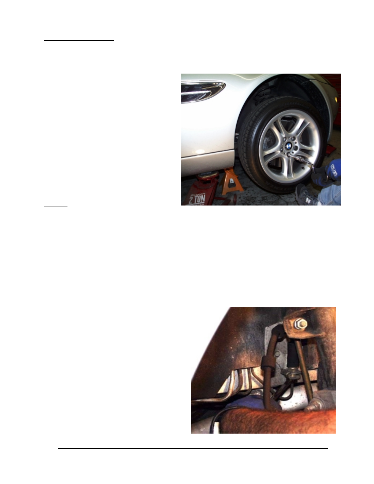
After securing the vehicle at a convenient
height, remove the front wheels.
Step 2Step 2
Step 2
Step 2Step 2
hotographs Shotographs S
hotographs S
hotographs Shotographs S
hoho
w Right Sw Right S
ho
w Right S
hoho
w Right Sw Right S
ide Iide I
nstallation Unstallation U
ide I
nstallation U
ide Iide I
nstallation Unstallation U
nless Nnless N
nless N
nless Nnless N
oted Ooted O
oted O
oted Ooted O
therther
ther
therther
wise.wise.
wise.
wise.wise.
Disconnect Stock Brake LineDisconnect Stock Brake Line
Disconnect Stock Brake Line
Disconnect Stock Brake LineDisconnect Stock Brake Line
WW
ARNING - ARNING -
W
ARNING -
WW
ARNING - ARNING -
br br
br
br br
NN
ote- Bote- B
N
ote- B
NN
ote- Bote- B
Place a drip tray or several rags directly below the inboard brake line connection. If the area
around the brake line connection to the chassis and strut is dirty, clean with brake cleaner or
appropriate cleaning agent
Use an 11mm flare wrench to slightly
loosen the hard line fitting from the stock
brake line.
Switch to an 11mm stubby wrench if available
and remove the rubber line from the hard line.
Place one of the rubber caps over the end of
the hard line. This should effectively control
fluid loss for the duration of the installation.
e sure sur
e sur
e sure sur
removed, it is likely more fluid will drip.removed, it is likely more fluid will drip.
removed, it is likely more fluid will drip.
removed, it is likely more fluid will drip.removed, it is likely more fluid will drip.
BB
rr
ake fluid will damage most painted surake fluid will damage most painted sur
B
r
ake fluid will damage most painted sur
BB
rr
ake fluid will damage most painted surake fluid will damage most painted sur
ake fluid frake fluid fr
ake fluid fr
ake fluid frake fluid fr
e the cap is secure the cap is secur
e the cap is secur
e the cap is secure the cap is secur
om any painted surom any painted sur
om any painted sur
om any painted surom any painted sur
ely installed on the master cylinderely installed on the master cylinder
ely installed on the master cylinder
ely installed on the master cylinderely installed on the master cylinder
faces.faces.
faces.
faces.faces.
faces. Ifaces. I
faces. I
faces. Ifaces. I
mmediately clean spilledmmediately clean spilled
mmediately clean spilled
mmediately clean spilledmmediately clean spilled
. If the cap is loose or. If the cap is loose or
. If the cap is loose or
. If the cap is loose or. If the cap is loose or
3541 Unit A, Lomita Boulevard, Torrance, CA 90505 (310) 325-4799
www.stoptech.com 7
Page 8
Step 3Step 3
Step 3
Step 3Step 3
Remove Stock Caliper & RotorRemove Stock Caliper & Rotor
Remove Stock Caliper & Rotor
Remove Stock Caliper & RotorRemove Stock Caliper & Rotor
Note: It is helpful to turn the steering away from the side you are working on so the
wrench handle clears the rear of the wheel well.
The Z8 has a pad wear sensor on the left front and right rear corners. These sensors can beThe Z8 has a pad wear sensor on the left front and right rear corners. These sensors can be
The Z8 has a pad wear sensor on the left front and right rear corners. These sensors can be
The Z8 has a pad wear sensor on the left front and right rear corners. These sensors can beThe Z8 has a pad wear sensor on the left front and right rear corners. These sensors can be
carcar
efully refully r
car
efully r
carcar
efully refully r
STST
-40 caliper-40 caliper
ST
-40 caliper
STST
-40 caliper-40 caliper
wrapped to the new brake line.wrapped to the new brake line.
wrapped to the new brake line.
wrapped to the new brake line.wrapped to the new brake line.
emoemo
emo
emoemo
vv
ed fred fr
om the stock brake pad and rom the stock brake pad and r
v
ed fr
om the stock brake pad and r
vv
ed fred fr
om the stock brake pad and rom the stock brake pad and r
. .
YY
ou will likely need to rou will likely need to r
.
Y
ou will likely need to r
. .
YY
ou will likely need to rou will likely need to r
e-insere-inser
e-inser
e-insere-inser
e-re-r
oute the lead wiroute the lead wir
e-r
oute the lead wir
e-re-r
oute the lead wiroute the lead wir
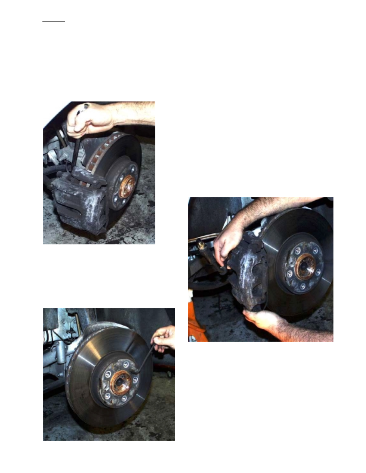
Remove the two stock caliper bolts with an 18mm
wrench or socket. Set these bolts aside for use in
a later step.
Caliper bolts may be very tight from the factory.
Ensure that you have a good purchase on the head
of the bolt and are in a good position to turn the
wrench or socket.
ted into the new pad in the Sted into the new pad in the S
ted into the new pad in the S
ted into the new pad in the Sted into the new pad in the S
e, which can typically be ty-e, which can typically be ty-
e, which can typically be ty-
e, which can typically be ty-e, which can typically be ty-
topTtopT
topT
topTtopT
echech
ech
echech
Remove the caliper with stock brake line
attached. There may be some leakage from
the open end of the brake line, especially if
the pads/pistons on the caliper are retracted.
Remove the stock rotor by first removing the
retaining bolt with a 6mm Allen wrench. It
may be necessary to strike the outer edge with
a non-marring hammer if corrosion prevents
the rotor from simply pulling off. If so, place a
wheel bolt in one of the holes first to prevent
the rotor from falling when it comes loose.
3541 Unit A, Lomita Boulevard, Torrance, CA 90505 (310) 325-4799
www.stoptech.com 8
Page 9
Step 4Step 4
Step 4
Step 4Step 4
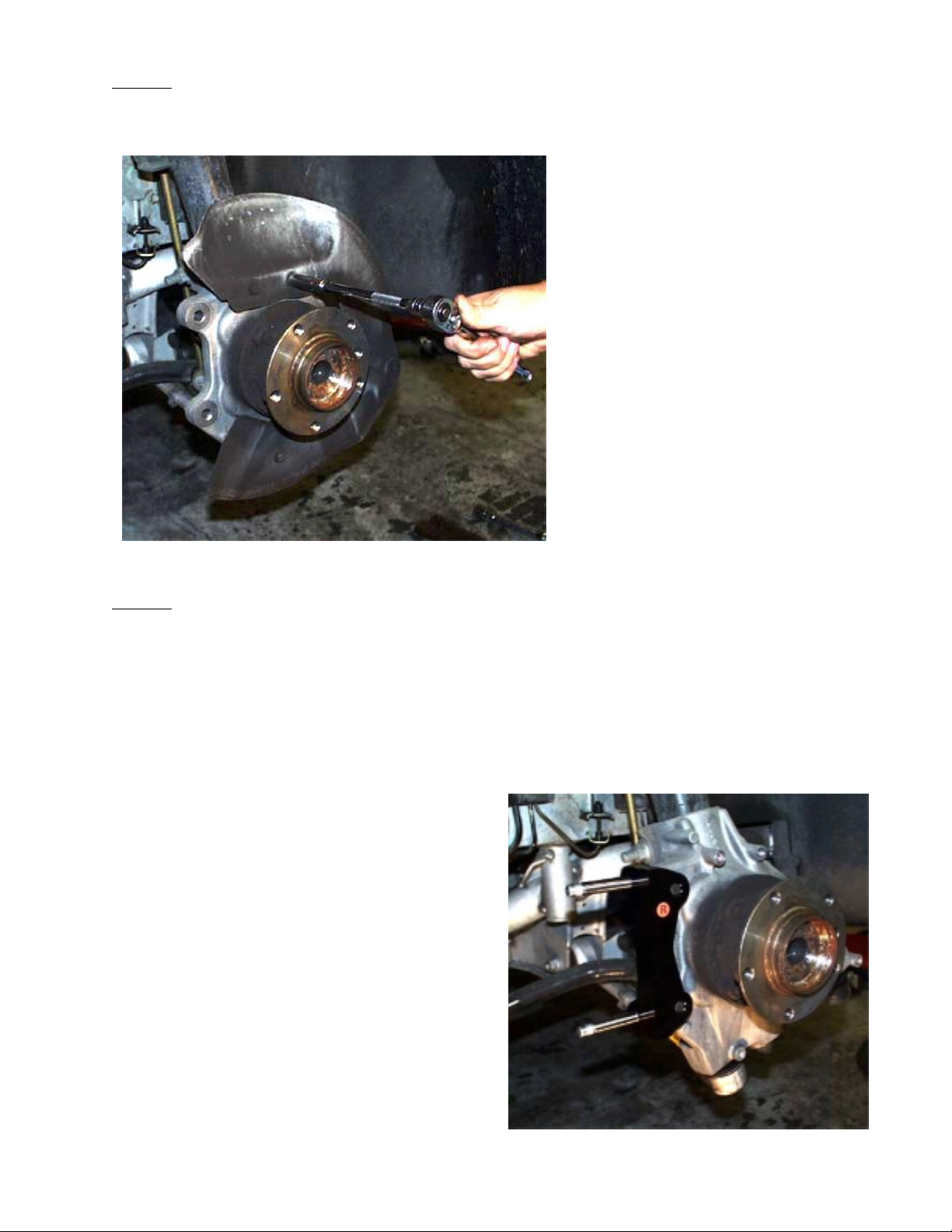
Remove Slash Guard/Dust Shield
Use a 10mm wrench or socket to
remove the four bolts holding the
dust shield.
Step 5Step 5
Step 5
Step 5Step 5
Install Caliper BracketInstall Caliper Bracket
Install Caliper Bracket
Install Caliper BracketInstall Caliper Bracket
The brackets are marked “L” & “R” for Left and Right sides of the vehicle as viewed
from the rear of the vehicle looking forward. It may be necessary to slightly clearance
the mounting lug on the knuckle. This modification in no way compromises the
strength of the part.
Bracket shown attached to knuckle using stock
caliper mounting bolts. Note studs face to the
rear and the bracket is located on the outboard
face of the mounting lugs. Test fit in this position to determine if the lug needs to be
clearanced.
3541 Unit A, Lomita Boulevard, Torrance, CA 90505 (310) 325-4799
www.stoptech.com 9
Page 10
Step 5Step 5
Step 5
Step 5Step 5
Install Caliper Bracket (continued)Install Caliper Bracket (continued)
Install Caliper Bracket (continued)
Install Caliper Bracket (continued)Install Caliper Bracket (continued)
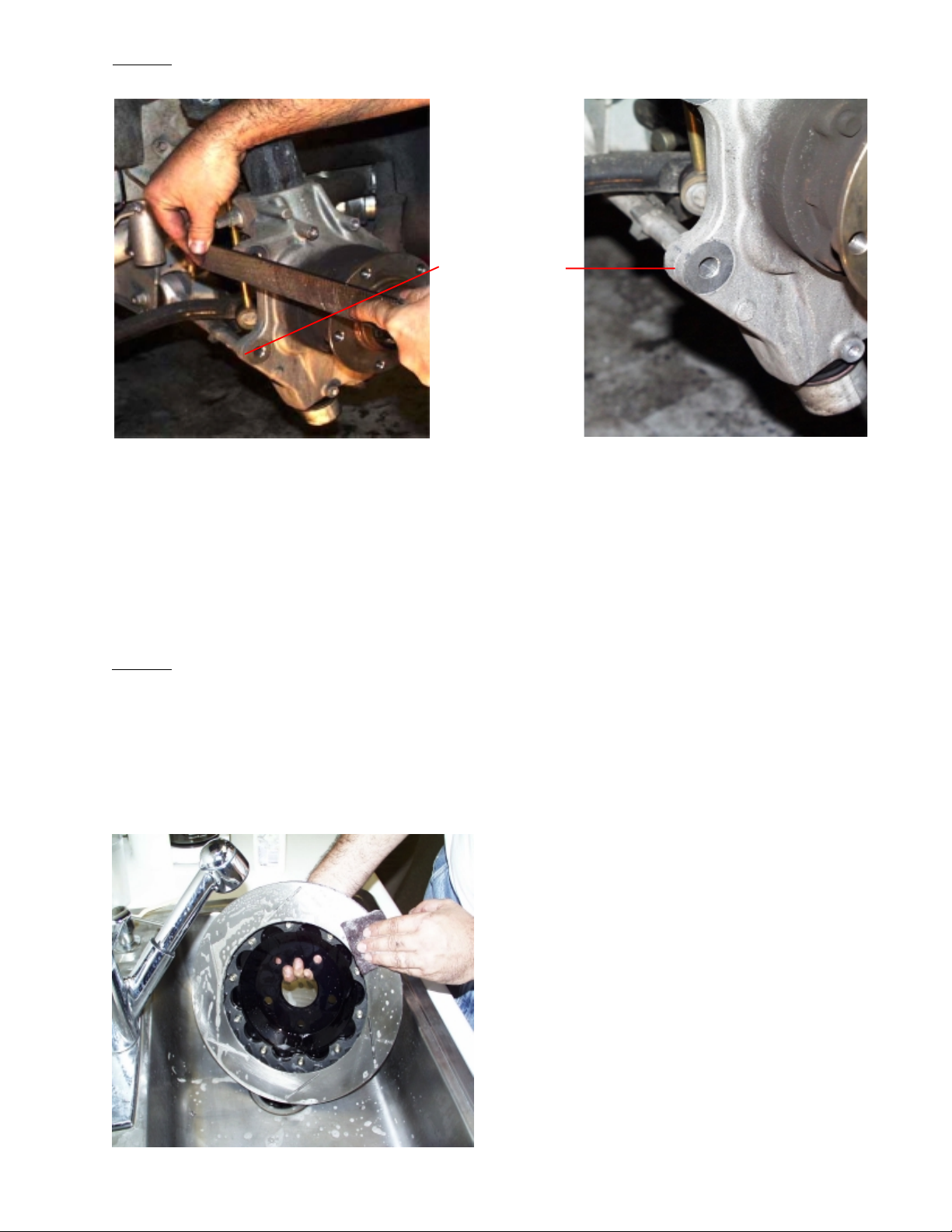
File this area
If the caliper bracket does not sit flat and the bolts do not line up, it may be necessary
to file the outer edge of the mounting lugs as shown above. The image to the right
shows the lower lug noting where to file.
After proper fit of the bracket has been confirmed, install the caliper bracket as shown
on the previous page.
Torque caliper bracket bolts to
Step 6Step 6
Step 6
Step 6Step 6
II
nstall Anstall A
I
nstall A
II
nstall Anstall A
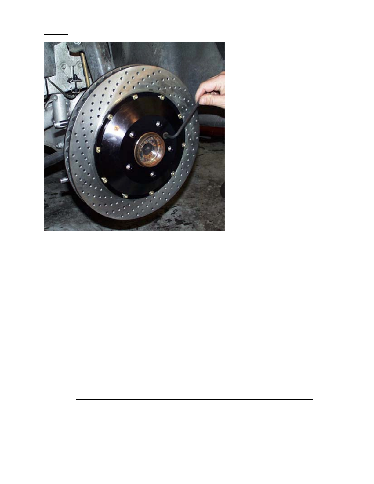
Rotors
will damage the rotors and pads and prevent the brakes from performing properly.
Even though it may not look like anything is washing off, the rust inhibitor is in
place and must be removed. Not cleaning the rotors will severely impact the performance of your new brake system.
erer
oRoR
otor Aotor A
er
oR
otor A
erer
oRoR
otor Aotor A
MUST MUST
MUST be cleaned with soap and water prior to installation. Not doing so
MUST MUST
ssemblyssembly
ssembly
ssemblyssembly
80-85 lb-ft80-85 lb-ft
80-85 lb-ft.
80-85 lb-ft80-85 lb-ft
Scrubbing AeroRotor with ScotchBrite pad,
soap and water.
Do not skip this step!
3541 Unit A, Lomita Boulevard, Torrance, CA 90505 (310) 325-4799
www.stoptech.com 10
Page 11
Step 6Step 6
Step 6
Step 6Step 6
(continued) (continued)
(continued)
(continued) (continued)
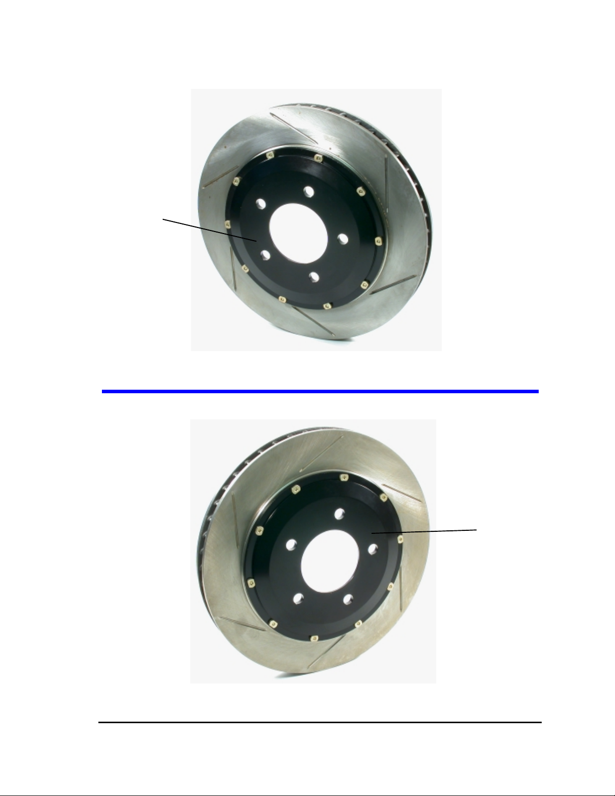
Install hat and rotor assembly
and hold in place with the stock
retaining fastener.
Be sure rotor is seated squarely
on hub face. If necessary, clean
the face of the hub with a wire
brush or similar means.
BB
e sure sur
B
BB
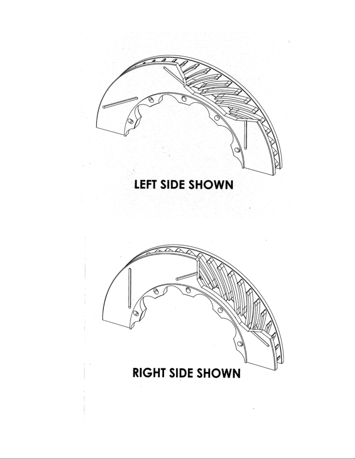
Reversing the rotors will severely decrease the cooling capac-Reversing the rotors will severely decrease the cooling capac-
Reversing the rotors will severely decrease the cooling capac-
Reversing the rotors will severely decrease the cooling capac-Reversing the rotors will severely decrease the cooling capacity of the system.ity of the system.
ity of the system.
ity of the system.ity of the system.
The rThe r
The r
The rThe r
on the rotor hats. If the tags are not legible, the vanes insideon the rotor hats. If the tags are not legible, the vanes inside
on the rotor hats. If the tags are not legible, the vanes inside
on the rotor hats. If the tags are not legible, the vanes insideon the rotor hats. If the tags are not legible, the vanes inside
the rotor should lean to the rear of the car on the top-side ofthe rotor should lean to the rear of the car on the top-side of
the rotor should lean to the rear of the car on the top-side of
the rotor should lean to the rear of the car on the top-side ofthe rotor should lean to the rear of the car on the top-side of
the rthe r
the r
the rthe r
(S(S
(S
(S(S
3541 Unit A, Lomita Boulevard, Torrance, CA 90505 (310) 325-4799
www.stoptech.com 11
e the re the r
e sur
e the r
e sure sur
e the re the r
otors arotors ar
otors ar
otors arotors ar
otorotor
otor
otorotor
ee Pee P
ages 12 & 13 for morages 12 & 13 for mor
ee P
ages 12 & 13 for mor
ee Pee P
ages 12 & 13 for morages 12 & 13 for mor
otor assemblies arotor assemblies ar
otor assemblies ar
otor assemblies arotor assemblies ar
e clearly mare clearly mar
e clearly mar
e clearly mare clearly mar
..
.
..
e on the corre on the corr
e on the corr
e on the corre on the corr
ked “Lked “L
ked “L
ked “Lked “L
e detailed images)e detailed images)
e detailed images)
e detailed images)e detailed images)
” and “R” and “R
” and “R
” and “R” and “R
ect side of the carect side of the car
ect side of the car
ect side of the carect side of the car
” with or” with or
” with or
” with or” with or
ange tagsange tags
ange tags
ange tagsange tags
..
.
..
Page 12
Outboard SideOutboard Side
Outboard Side
Outboard SideOutboard Side
Left Side Rotor
Right Side Rotor
DD
D
DD
rivriv
riv
rivriv
erer
er
erer
’’
s Lefts Left
’
s Left
’’
s Lefts Left
Outboard SideOutboard Side
Outboard Side
Outboard SideOutboard Side
DD
rivriv
erer
’’
3541 Unit A, Lomita Boulevard, Torrance, CA 90505 (310) 325-4799
www.stoptech.com 12
D
DD
riv
rivriv
s Rights Right
er
’
s Right
erer
’’
s Rights Right
Page 13
3541 Unit A, Lomita Boulevard, Torrance, CA 90505 (310) 325-4799
www.stoptech.com 13
Page 14
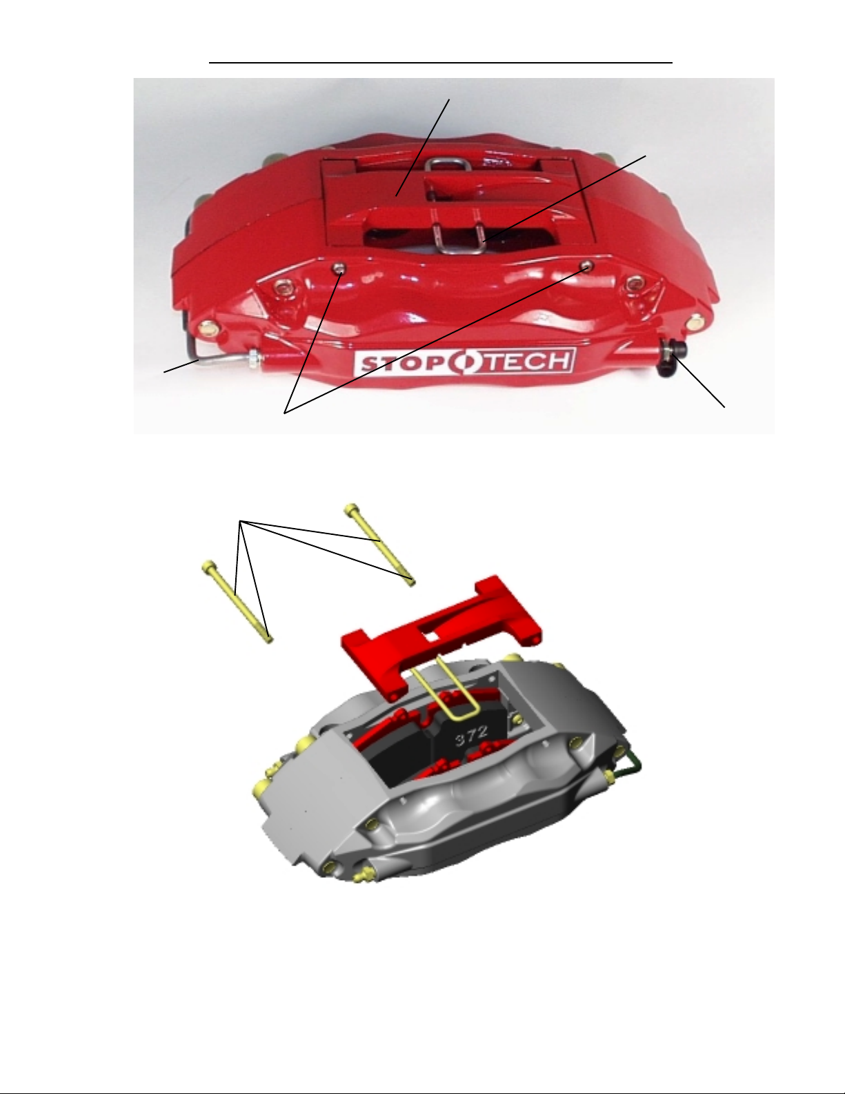
Cross Over Tube
Caliper Component Identification
Bolt-in Bridge
Pad Retaining Clip
Bridge Bolts
Use a light film of Anti-Sieze on Bridge
Bolt shaft and threads
Bleed Screw
The ST-40 caliper uses a Porsche style pad.
The Friction Materials Standards Institute (FMSI) number for the pad backing plate is
D372
Please see the FAQ section of our website for further pad
interchange information. www.stoptech.com
15
Page 15
Step 7Step 7
Step 7
Step 7Step 7
Install Caliper and PadsInstall Caliper and Pads
Install Caliper and Pads
Install Caliper and PadsInstall Caliper and Pads
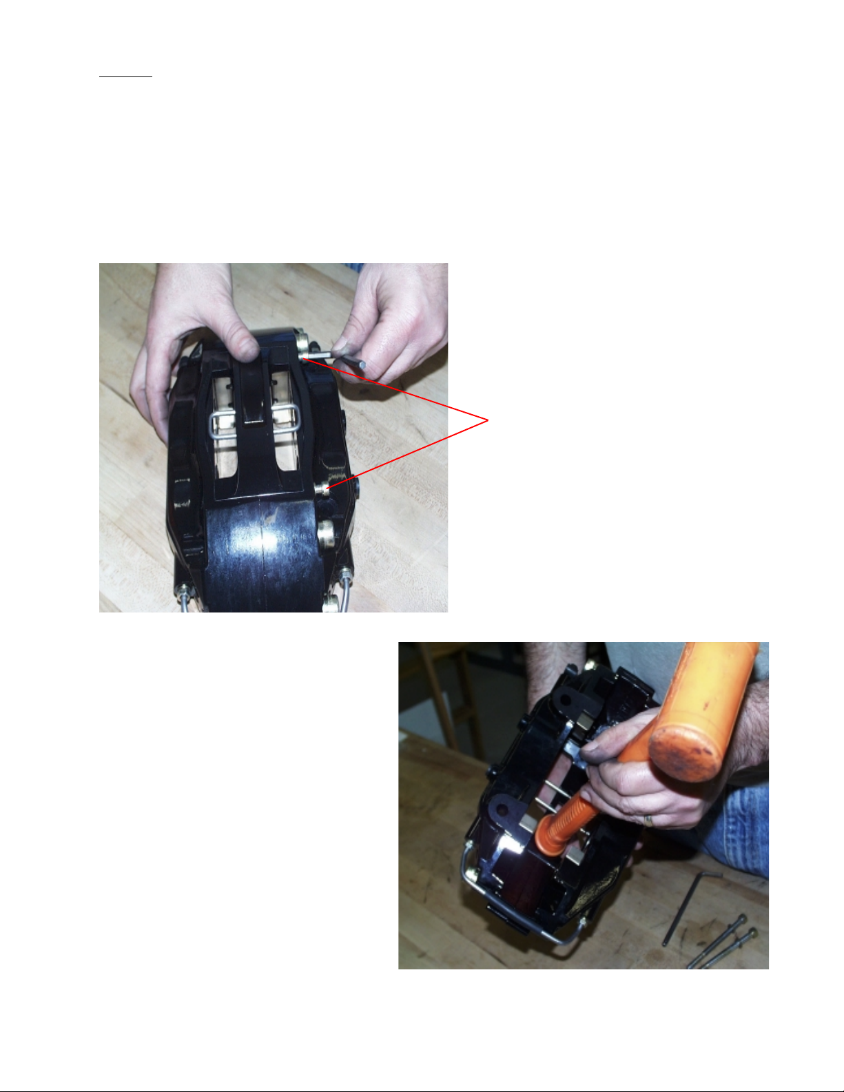
- Determine the left and right side calipers. The calipers are marked on each box. As a
check, the bleed screws always go to the top of the caliper.
Remove the 2 bolts holding the caliper bridge using a 5mm Allen wrench.
Remove the caliper bridge taking note of the direction it is installed in and the correct location of
the pad retaining wire clip, which typically, but not always, stays attached to the bridge.
Bridge Bolts
In order to stiffen the caliper, the
bridge is a snug fit and the bolts
may be tight when removing. Keep
turning bolts gently with pressure
applied in the direction of removal.
After removing the bolts, it may be
necessary to tap the bridge out from
the inside of the caliper with a plastic or leather hammer or similar
tool. The handle of a tool works well
for this. With use, the bridge and
bolt will become easier to remove
and install.
3541 Unit A, Lomita Boulevard, Torrance, CA 90505 (310) 325-4799
www.stoptech.com 15
Page 16
Step 7 (Continued)Step 7 (Continued)
Step 7 (Continued)
Step 7 (Continued)Step 7 (Continued)
Note- Images on this and the following page may not be of the vehicle notedNote- Images on this and the following page may not be of the vehicle noted
Note- Images on this and the following page may not be of the vehicle noted
Note- Images on this and the following page may not be of the vehicle notedNote- Images on this and the following page may not be of the vehicle noted
however they are a proper represention of the correct installation.however they are a proper represention of the correct installation.
however they are a proper represention of the correct installation.
however they are a proper represention of the correct installation.however they are a proper represention of the correct installation.
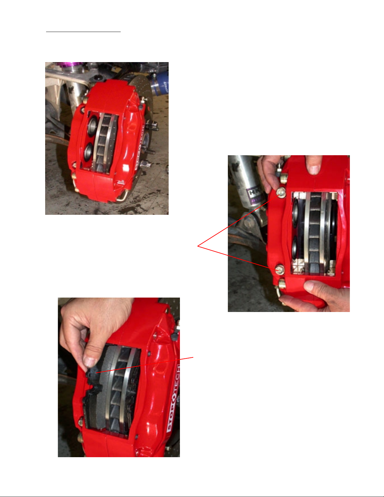
Install the caliper onto the adapter bracket studs with
the bleed screws on the top side of the caliper.
Slide the caliper over the mounting studs, making
sure it is square and evenly started on both studs. It
may necessary to gently tap the caliper into position
with a non-marring hammer or mallet.
Install the Jet nuts onto each stud with
one 12mm washer under each nut
Tighten the Jet nuts to
of torque using a 1/2” socket.
40-45 lb-ft40-45 lb-ft
40-45 lb-ft
40-45 lb-ft40-45 lb-ft
Slide the brake pads into position in the
calipers. Be sure the friction side of each
pad is facing the rotor.
(Yes, they have been installed backward before!)
3541 Unit A, Lomita Boulevard, Torrance, CA 90505 (310) 325-4799
www.stoptech.com 16
Page 17
Step 7 (continued)Step 7 (continued)
Step 7 (continued)
Step 7 (continued)Step 7 (continued)
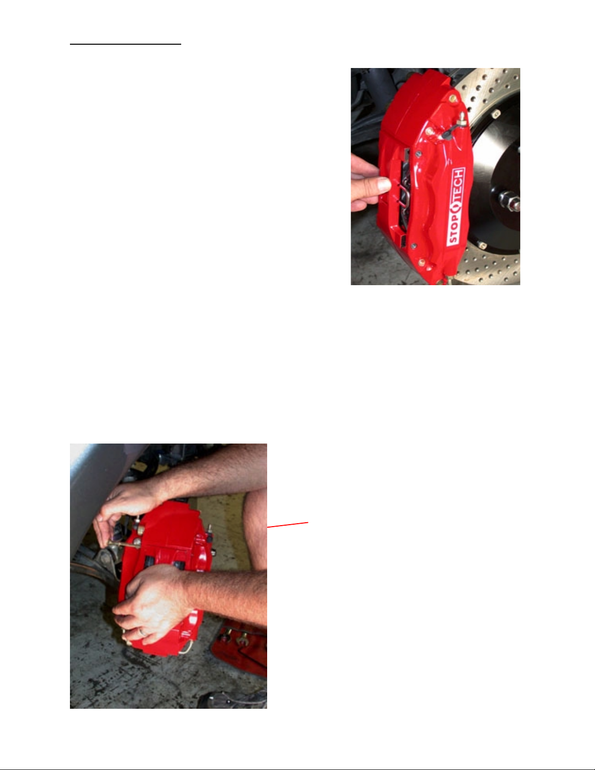
Install the bridge by sliding it into position and
rocking it until one of the bolt holes lines up.
Be sure the bridge is slid straight and parallel
into the caliper body opening.
Note: The bridge is directional and theNote: The bridge is directional and the
Note: The bridge is directional and the
Note: The bridge is directional and theNote: The bridge is directional and the
““
air-scoopair-scoop
“
air-scoop
““
air-scoopair-scoop
Supra kit.Supra kit.
Supra kit.
Supra kit.Supra kit.
Apply a light film of anti-sieze compound onto the bridge bolt shaft and threads. Insert the
first bridge bolt and start the first few threads using a 5mm Allen wrench. Gently press the
opposite side of the bridge with the palm of your hand, or tap with a mallet until the second
bolt engages the hole. With pressure still applied, start the second bolt. Torque each bolt to
8-10 lb-ft.8-10 lb-ft.
8-10 lb-ft. DO NOT OVER TORQUE BRIDGE BOLTS! Snug is tight enough.
8-10 lb-ft.8-10 lb-ft.
” detail should face do” detail should face do
” detail should face do
” detail should face do” detail should face do
wn on thewn on the
wn on the
wn on thewn on the
If the fit of the bridge into the caliper is tight it may be necessary to tap into position with
a mallet. While applying pressure to the bolt head, adjust the position of the bridge until
the bolt slides more freely into place.
WW
ARNING: ARNING:
W
ARNING: DO NOT HAMMER BRIDGE
WW
ARNING: ARNING:
BOLBOL
TT
BOL
BOLBOL
SS
T
S INTO PLACE, TAP BRIDGE, NOT BOLTS.
TT
SS
Apply pressure to head of bolt
If necessary, apply pressure on bridge to position properly. Do not hammer bridge too deep
into the caliper as you may deform the pad
retaining spring clip.
3541 Unit A, Lomita Boulevard, Torrance, CA 90505 (310) 325-4799
www.stoptech.com 17
Page 18
Step 8Step 8
Step 8
Step 8Step 8
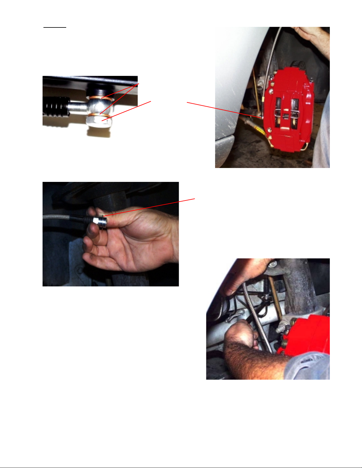
Attach the stainless brake line
Install the banjo bolt into the caliper with a copper crush
washer on each side of the Banjo fitting. Route the line
vertically, approximately parallel with the caliper body.
Copper Crush Washers
Banjo Bolt
apprappr
oo
Torque to
The Banjo bolt only needs to be tightened enough to seal
the crush washers. Excessive torque can damage the
threads inside the caliper and/or damage the Banjo bolt.
appr
apprappr
ximately 14 lb-ft ximately 14 lb-ft
o
ximately 14 lb-ft using a 14mm wrench.
oo
ximately 14 lb-ft ximately 14 lb-ft
Use a 14mm wrench to hold the stainless line
inboard fitting while using the flare wrench to
tighten the hard line fitting.
Note- It may help to have the wheels straight
to access the fittings with the wrenches.
After securing the line, turn the wheels lockto-lock to make sure the line is not binding
of touching any moving parts of the suspension. Adjust as necessary by re-clocking the
Banjo bolt on the caliper.
Place the stainless steel washer over the
inboard brake line fitting as shown.
Remove the rubber cap from the hard line and
screw the fitting into the new brake line by
hand for a few turns before tightening with an
11mm flare wrench.
The Z8 has a pad wear sensor on the left front and right rear corners. These sensors
can be carefully removed from the stock brake pad and re-inserted into the new pad
in the StopTech ST-40 caliper. You will likely need to re-route the lead wire, which
can typically be ty-wrapped to the new brake line.
3541 Unit A, Lomita Boulevard, Torrance, CA 90505 (310) 325-4799
www.stoptech.com 18
Page 19

Step 9
Bleed BrakesBleed Brakes
Bleed Brakes
Bleed BrakesBleed Brakes
Complete installation on both sides of the vehicle before bleeding the system.
Note: The calipers and lines will need to fill with fluid, quickly draining the master cylinder reservoir. Keep a close watch on the fluid level when initially bleeding the system. Do not allow the
master cylinder reservoir to run dry and draw in air. Doing so may require the brake system to be
serviced by a certified brake technician.
Bleed the brake system using an 11mm wrench on the bleed screws:
- The sequence for bleeding the brakes should be:
1. Right outboard bleed screw
2. Right inboard bleed screw
3. Left outboard bleed screw
4. Left inboard bleed screw
Though a torque wrench is typically NOT used on bleed screws, as a reference, torque for bleed
screws should be
100-140 INCH/P100-140 INCH/P
100-140 INCH/P
100-140 INCH/P100-140 INCH/P
oundsounds
ounds.
oundsounds
After initially bleeding the system, gently tap the caliper body with a non-marring mallet or
hammer to dislodge any small air bubbles and re-bleed.
After bleeding, apply a constant pressure to the brake pedal and check all connections,After bleeding, apply a constant pressure to the brake pedal and check all connections,
After bleeding, apply a constant pressure to the brake pedal and check all connections,
After bleeding, apply a constant pressure to the brake pedal and check all connections,After bleeding, apply a constant pressure to the brake pedal and check all connections,
including bleed screws, and both ends of the line for leaks.including bleed screws, and both ends of the line for leaks.
including bleed screws, and both ends of the line for leaks.
including bleed screws, and both ends of the line for leaks.including bleed screws, and both ends of the line for leaks.
BB
rake fluid will damage most painted surrake fluid will damage most painted sur
B
rake fluid will damage most painted sur
BB
rake fluid will damage most painted surrake fluid will damage most painted sur
any painted surany painted sur
any painted sur
any painted surany painted sur
chemicals, prolonged exposure will damage the finish.chemicals, prolonged exposure will damage the finish.
chemicals, prolonged exposure will damage the finish.
chemicals, prolonged exposure will damage the finish.chemicals, prolonged exposure will damage the finish.
face, including the caliperface, including the caliper
face, including the caliper
face, including the caliperface, including the caliper
facesfaces
. I. I
faces
facesfaces
. .
Though caliper paint is designed to rThough caliper paint is designed to r
.
Though caliper paint is designed to r
. .
Though caliper paint is designed to rThough caliper paint is designed to r
mmediately clean spilled brake fluid frmmediately clean spilled brake fluid fr
. I
mmediately clean spilled brake fluid fr
. I. I
mmediately clean spilled brake fluid frmmediately clean spilled brake fluid fr
esist harshesist harsh
esist harsh
esist harshesist harsh
omom
om
omom
3541 Unit A, Lomita Boulevard, Torrance, CA 90505 (310) 325-4799
www.stoptech.com
19
Page 20

Step 10Step 10
Step 10
Step 10Step 10
Re-install wheelsRe-install wheels
Re-install wheels
Re-install wheelsRe-install wheels
Check wheel to caliper clearance before installing wheels!Check wheel to caliper clearance before installing wheels!
Check wheel to caliper clearance before installing wheels!
Check wheel to caliper clearance before installing wheels!Check wheel to caliper clearance before installing wheels!
Note: Some wheels are balanced on the inside with adhesive backed lead. If theNote: Some wheels are balanced on the inside with adhesive backed lead. If the
Note: Some wheels are balanced on the inside with adhesive backed lead. If the
Note: Some wheels are balanced on the inside with adhesive backed lead. If theNote: Some wheels are balanced on the inside with adhesive backed lead. If the
lead is on the outboarlead is on the outboar
lead is on the outboar
lead is on the outboarlead is on the outboar
If necessarIf necessar
If necessar
If necessarIf necessar
furfur
ther inboarther inboar
fur
ther inboar
furfur
ther inboarther inboar
you should check the wheel weight positions on all four wheels and the spare asyou should check the wheel weight positions on all four wheels and the spare as
you should check the wheel weight positions on all four wheels and the spare as
you should check the wheel weight positions on all four wheels and the spare asyou should check the wheel weight positions on all four wheels and the spare as
well if it is full sized.well if it is full sized.
well if it is full sized.
well if it is full sized.well if it is full sized.
Re-install the wheels and torque the lug nuts to your wheel manufacturer’s specifications. It may be
necessary to snug the bolts before lowering the vehicle and then torque the wheels when the car is
on the ground. Alternatively, an assistant may depress the brake pedal while you tighten the wheel
nuts to the proper torque setting.
yy
, note w, note w
y
, note w
yy
, note w, note w
d or outboard or outboar
d or outboar
d or outboard or outboar
d edge, behind the spokes, it may interd edge, behind the spokes, it may inter
d edge, behind the spokes, it may inter
d edge, behind the spokes, it may interd edge, behind the spokes, it may inter
eight and location and place a new piece of the same weight and location and place a new piece of the same w
eight and location and place a new piece of the same w
eight and location and place a new piece of the same weight and location and place a new piece of the same w
d to clear the caliperd to clear the caliper
d to clear the caliper
d to clear the caliperd to clear the caliper
. If y. If y
. If y
. If y. If y
ou rou r
ou r
ou rou r
ferfer
e with the calipere with the caliper
fer
e with the caliper
ferfer
e with the calipere with the caliper
otate tirotate tir
otate tir
otate tirotate tir
es res r
es r
es res r
egularlyegularly
egularly
egularlyegularly
eighteight
eight
eighteight
..
.
..
,,
,
,,
Carefully test-drive the vehicle in a safe area at low speed to insure all components are working
correctly. Then, follow pad and rotor break-in procedures on following pages.
All trademarks are properties of their respective owners. StopTech LLC is not associated or
affiliated with or sponsored by BMW.
3541 Unit A, Lomita Boulevard, Torrance, CA 90505 (310) 325-4799
www.stoptech.com 20
Page 21

AeroRotorTM Installation & Break-in Procedure
READ READ
READ
READ READ
FF
AILAIL
AIL
AILAIL
URE URE
URE
URE URE
WW
W
WW
F
FF
WILL CAUSE PERMANANT DAMAGE TO YOUR BRAKE ROTORS ANDWILL CAUSE PERMANANT DAMAGE TO YOUR BRAKE ROTORS AND
WILL CAUSE PERMANANT DAMAGE TO YOUR BRAKE ROTORS AND
WILL CAUSE PERMANANT DAMAGE TO YOUR BRAKE ROTORS ANDWILL CAUSE PERMANANT DAMAGE TO YOUR BRAKE ROTORS AND
KEEP KEEP
KEEP
KEEP KEEP
The majority of brake system problems are due to improper installation and/or break-in of the
rotors and pads. By reading and understanding the following, you will avoid the most common
causes of poor brake performance and vibration. FAILURE TO READ AND UNDERSTAND THIS
MAY CAUSE SERIOUS PERMENANT DAMAGE TO YOUR NEW ROTORS.
StopTech coats non-plated AeroRotors with a water soluable, environmentally friendly rust inhibitor that MUST be cleaned before use. A non-plated rotor looks like bare metal, plated rotors are
bright silver in color and do not need to be washed. Even though you may not see a change in the
rotor color, if the rotor is not rusty, the rust inhibitor is there. Use soap and water, NOT BRAKE
CLEANER to wash the rotors. A small piece of Scothbrite works well to scrub with. When cleaned
and rinsed properly, the surface of the rotor will immediately show a light rust color which is
normal.
TT
O READ, UNDERSTO READ, UNDERST
T
O READ, UNDERST
TT
O READ, UNDERSTO READ, UNDERST
THE SYSTEM FRTHE SYSTEM FR
THE SYSTEM FR
THE SYSTEM FRTHE SYSTEM FR
ash Nash N
ash N
ash Nash N
AND AND
AND
AND AND
on-Pon-P
on-P
on-Pon-P
WW
W
WW
THIS NOTHIS NO
THIS NO
THIS NOTHIS NO
AND AND FOLLAND AND FOLL
AND AND FOLL
AND AND FOLLAND AND FOLL
OM OM
WW
OM
OM OM
lated Alated A
lated A
lated Alated A
AA
TER beforTER befor
A
TER befor
AA
TER beforTER befor
ORKING AORKING A
W
ORKING A
WW
ORKING AORKING A
erer
er
erer
T ITT IT
T IT
T ITT IT
oRoR
oR
oRoR
e installation.e installation.
e installation.
e installation.e installation.
OO
W W
THESE PRTHESE PR
O
W
THESE PR
OO
W W
THESE PRTHESE PR
’S FULL CAP’S FULL CAP
’S FULL CAP
’S FULL CAP’S FULL CAP
otors with SOotors with SO
otors with SO
otors with SOotors with SO
OCEDURESOCEDURES
OCEDURES
OCEDURESOCEDURES
AA
CITCIT
YY
A
AA
CIT
CITCIT
Y
YY
..
.
..
WW
W
WW
APAP
AP
APAP
BB
rr
eak in yeak in y
B
r
eak in y
BB
rr
eak in yeak in y
lolo
wing the prwing the pr
lo
wing the pr
lolo
wing the prwing the pr
opposite side of this page.opposite side of this page.
opposite side of this page.
opposite side of this page.opposite side of this page.
Breaking in rotors and pads is critical to the optimum performance of your new brakes. When
breaking in new parts, you are not only heat cycling the pads, but depositing a layer of pad material
onto the rotor face as well. If not broken in properly, an uneven layer of pad material will be depos-
ited onto the rotor causing vibration.
attributed to uneven pad deposition.attributed to uneven pad deposition.
attributed to uneven pad deposition.
attributed to uneven pad deposition.attributed to uneven pad deposition.
NN
ote: Pote: P
N
ote: P
NN
ote: Pote: P
faces BEFORE starfaces BEFORE star
faces BEFORE star
faces BEFORE starfaces BEFORE star
is woris wor
is wor
is woris wor
Typically, a heavy braking street driver will experience approximately 1 to 1.1G’s of deceleration. At
this rate, ABS will be activated on such equipped vehicles. A moderate braking effort is needed to
properly break in rotors and pads. If ABS intervention or lock-up was called 100% brake effort, a
stopping force of approximately 70-80%, just short of ABS intervention or lock-up is a general
estimate of pedal effort you are trying to achieve.
lated rlated r
lated r
lated rlated r
n off, typically sevn off, typically sev
n off, typically sev
n off, typically sevn off, typically sev
our new pads and rour new pads and r
our new pads and r
our new pads and rour new pads and r
ocedurocedur
ocedur
ocedurocedur
otors must be drivotors must be driv
otors must be driv
otors must be drivotors must be driv
ting the brting the br
ting the br
ting the brting the br
eak-in preak-in pr
eak-in pr
eak-in preak-in pr
erer
al miles of driving.al miles of driving.
er
al miles of driving.
erer
al miles of driving.al miles of driving.
e described beloe described belo
e described belo
e described beloe described belo
VV
irir
tually evtually ev
V
ir
tually ev
VV
irir
tually evtually ev
en with gentle bren with gentle br
en with gentle br
en with gentle bren with gentle br
ocedurocedur
ocedur
ocedurocedur
(Please see other side)(Please see other side)
(Please see other side)
(Please see other side)(Please see other side)
otors botors b
otors b
otors botors b
erer
y instance of a “y instance of a “
er
y instance of a “
erer
y instance of a “y instance of a “
aking until CAD plating is woraking until CAD plating is wor
aking until CAD plating is wor
aking until CAD plating is woraking until CAD plating is wor
e. De. D
o not use bro not use br
e. D
o not use br
e. De. D
o not use bro not use br
y cary car
y car
y cary car
w and on thew and on the
w and on the
w and on thew and on the
akes aggrakes aggr
akes aggr
akes aggrakes aggr
efully fol-efully fol-
efully fol-
efully fol-efully fol-
warpedwarped
warped
warpedwarped
essivessiv
essiv
essivessiv
” r” r
otor isotor is
” r
otor is
” r” r
otor isotor is
n off rn off r
n off r
n off rn off r
ely until platingely until plating
ely until plating
ely until platingely until plating
otorotor
otor
otorotor
Document: 98-300-0001
Rev. I 06-27-02
3541 Unit A, Lomita Boulevard, Torrance, CA 90505 (310) 325-4799
www.stoptech.com
Page 22

Rotor and Pad Break-in (continued)
Note-Note-
Note-
Note-NoteBedding of pads should not be done in wet weather or wet road conditions.Bedding of pads should not be done in wet weather or wet road conditions.
Bedding of pads should not be done in wet weather or wet road conditions.
Bedding of pads should not be done in wet weather or wet road conditions.Bedding of pads should not be done in wet weather or wet road conditions.
After completeing installation, make a series of 10 stops from 60 to 5-10 MPH. At the end of each
stop, immediately accelerate to 60 again for the next stop. Run all stops in one cycle.
During the 60 to 5-10 MPH series of stops, the exact speed is not critical. Accelerate to appoximately
60 and begin the braking cycle. As you approach 5-10 MPH, it is not necessary to watch the
speedometer, keep your eyes on the road and approximate your speed at the end of each cycle.
DO NOT COME TO A COMPLETE STOP, AS YOU WILL IMPRINT PAD MATERIAL ONTO
THE ROTOR, CAUSING A VIBRATION.
There are several indicators to look for while breaking in the system:
On the 8th or 9th stop, there should be a distinct smell from the brakes. Smoke may be evident after
several stops as well.
Also on the 8th or 9th stop, some friction materials will experience “green fade”. This is a slight
fading of the brakes. The fade will stabilize, but not completely go away until the brakes have
cooled.
After the break-in cycle is finished, there will be a blue tint color on the rotor with a light gray film
on the rotor face. The blue tint indicates the rotor has reached the proper break-in temperature and
the gray film is pad material starting to transfer onto the rotor face. This is normal and good!
II
f racing or higher perf racing or higher per
I
f racing or higher per
II
f racing or higher perf racing or higher per
if a full race pad, four stops from 100 to 5-10 mph.if a full race pad, four stops from 100 to 5-10 mph.
if a full race pad, four stops from 100 to 5-10 mph.
if a full race pad, four stops from 100 to 5-10 mph.if a full race pad, four stops from 100 to 5-10 mph.
After the first break in cycle shown above, the brakes will still not be operatingAfter the first break in cycle shown above, the brakes will still not be operating
After the first break in cycle shown above, the brakes will still not be operating
After the first break in cycle shown above, the brakes will still not be operatingAfter the first break in cycle shown above, the brakes will still not be operating
at their best capacityat their best capacity
at their best capacity
at their best capacityat their best capacity
the brakes rthe brakes r
the brakes r
the brakes rthe brakes r
down in between each cycle.down in between each cycle.
down in between each cycle.
down in between each cycle.down in between each cycle.
SS
topTtopT
S
SS
speed limit, do so in a safe area, away from traffic at your own risk.speed limit, do so in a safe area, away from traffic at your own risk.
speed limit, do so in a safe area, away from traffic at your own risk.
speed limit, do so in a safe area, away from traffic at your own risk.speed limit, do so in a safe area, away from traffic at your own risk.
After the final stop of each cycle, drive as much as possible without using the brakes to cool off the
system. Ideally, the brakes should be allowed to cool to ambient temperature before using again.
DO NODO NO
DO NO
DO NODO NO
YY
Y
YY
THE RTHE R
THE R
THE RTHE R
ech does not endorse speeding on public rech does not endorse speeding on public r
topT
ech does not endorse speeding on public r
topTtopT
ech does not endorse speeding on public rech does not endorse speeding on public r
T CT C
T C
T CT C
OUR FOOOUR FOO
OUR FOO
OUR FOOOUR FOO
OO
O
OO
OME OME
OME
OME OME
T ON T ON
T ON
T ON T ON
TT
OR CAOR CA
T
OR CA
TT
OR CAOR CA
eally stareally star
eally star
eally stareally star
forfor
mance pads armance pads ar
for
mance pads ar
forfor
mance pads armance pads ar
. A second or thir. A second or thir
. A second or thir
. A second or thir. A second or thir
t to “t to “
t to “
t to “t to “
TT
O A CO A C
T
O A C
TT
O A CO A C
THE PTHE P
THE P
THE PTHE P
USING A USING A
USING A
USING A USING A
EDAL. PEDAL. P
EDAL. P
EDAL. PEDAL. P
e being used, add four stops fre being used, add four stops fr
e being used, add four stops fr
e being used, add four stops fre being used, add four stops fr
come income in
come in
come income in
OMPLETE STOMPLETE ST
OMPLETE ST
OMPLETE STOMPLETE ST
AD MAAD MA
AD MA
AD MAAD MA
VIBRAVIBRA
VIBRA
VIBRAVIBRA
TION.TION.
TION.
TION.TION.
d bed-in cyd bed-in cy
d bed-in cy
d bed-in cyd bed-in cy
”. A “”. A “
”. A “
”. A “”. A “
OP OP
OP
OP OP
cycy
cy
cycy
WHEN WHEN
WHEN
WHEN WHEN
TERIAL TERIAL
TERIAL
TERIAL TERIAL
om 80 to 5-10mph andom 80 to 5-10mph and
om 80 to 5-10mph and
om 80 to 5-10mph andom 80 to 5-10mph and
cle is typically necessarcle is typically necessar
cle is typically necessar
cle is typically necessarcle is typically necessar
clecle
” is a series of stops with a cool” is a series of stops with a cool
cle
” is a series of stops with a cool
clecle
” is a series of stops with a cool” is a series of stops with a cool
oads. If going abooads. If going abo
oads. If going abo
oads. If going abooads. If going abo
THE SYSTEM IS HOTHE SYSTEM IS HO
THE SYSTEM IS HO
THE SYSTEM IS HOTHE SYSTEM IS HO
WILL IMMEDIAWILL IMMEDIA
WILL IMMEDIA
WILL IMMEDIAWILL IMMEDIA
TELTEL
TEL
TELTEL
T AND LEAT AND LEA
T AND LEA
T AND LEAT AND LEA
Y Y
TRANSFER TRANSFER
Y
TRANSFER
Y Y
TRANSFER TRANSFER
y befory befor
y befor
y befory befor
vv
e the legale the legal
v
e the legal
vv
e the legale the legal
VEVE
VE
VEVE
TT
T
TT
OO
O
OO
ee
e
ee
If you have any questions about rotor and pad break in, or any aspect of your StopTech brake kit or
brakes in general, please contact our Customer Service Department at 310-325-4799 X 105 or e-mail
us at [email protected]
Page 23

Thank you for selecting StopTech, we realize you had a choice
in selecting a big brake upgrade for your vehicle and know youll
be happy with our system.
We proudly support our fine products. For any assistance or
questions, please contact our Customer Service Departmant
at
(310) 325-4799 extension 105
or e-mail us at
 Loading...