

Page 1
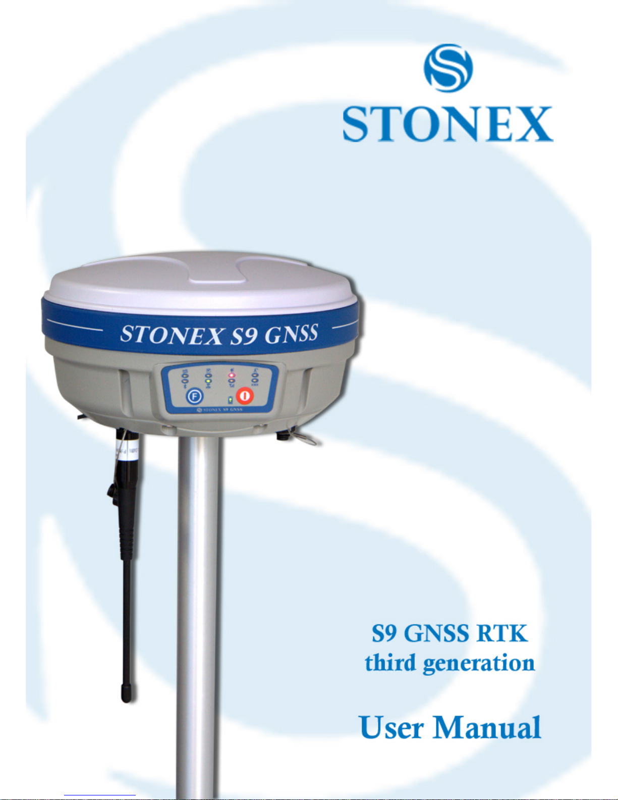
Page 2

Contents
1
Contents
Chapter I : A brief introduction of S9III ............................................................................................................... 3
Chapter II: S9III mainframe .................................................................................................................................... 6
II.1 The outlook of mainframe ........................................................................................................................................................................6
II.2 Interfaces ........................................................................................................................................................................................................6
II.3 The installation of battery ........................................................................................................................................................................8
II.4 Indicator leds and instrument setup ...................................................................................................................................................9
Chapter III: S9III standard accessories .............................................................................................................. 14
III.1 The case of S9III ...................................................................................................................................................................................... 14
III.2 Power supply ............................................................................................................................................................................................ 16
III.3 The antennas............................................................................................................................................................................................. 17
III.4 Cables ............................................................................................................................................................................................................ 19
III.5 Other accessories .................................................................................................................................................................................... 20
III.6 Controller Getac PS236 ......................................................................................................................................................................... 22
Chapter IV: S9III Configuration ............................................................................................................................ 23
IV.1 The installation of base and rover ..................................................................................................................................................... 23
IV.2 The configuration by using keys ....................................................................................................................................................... 24
IV.3 Standard operation of leds .................................................................................................................................................................... 26
IV.4 How to measure the antenna height ............................................................................................................................................... 27
IV.5 How to download static data ................................................................................................................................................................ 29
IV.6 Registration of the receiver ................................................................................................................................................................. 30
Chapter V: STONEX® Assistant for S9III............................................................................................................. 31
V.1 Start Stonex Assistant on your PC. .................................................................................................................................................... 32
V.3 Settings ........................................................................................................................................................................................................... 34
V.3.1. Static Data Survey .................................................................................................................................................................................. 35
V.3.2. Dynamic working mode .................................................................................................................................................................... 37
V.3.2.1. Base coordinates setting ............................................................................................................................................................... 38
V.3.3. Data Link .................................................................................................................................................................................................. 41
V.3.3.1 Network................................................................................................................................................................................................. 41
Page 3

Contents
2
V.3.3.2 UHF Radio ............................................................................................................................................................................................ 44
V.3.3.3 External ................................................................................................................................................................................................. 46
V.3.3.4. Bluetooth ............................................................................................................................................................................................. 47
V.3.4 NMEA Output string. ............................................................................................................................................................................. 48
V.4 Register the receiver ................................................................................................................................................................................ 51
V.6 Firmware update ...................................................................................................................................................................................... 53
Appendix 1: Default Radio Settings .................................................................................................................... 54
Appendix 2: Self-check procedure ...................................................................................................................... 57
Appendix 3: Technical Specifications ................................................................................................................ 58
GNNS module specifications: ....................................................................................................................................................................... 58
Receiver accuracy ............................................................................................................................................................................................. 59
Connection devices and protocols : ........................................................................................................................................................... 59
Radio module ...................................................................................................................................................................................................... 60
GPRS/GSM module ........................................................................................................................................................................................... 60
Power Supply: .................................................................................................................................................................................................... 60
Physical specification: .................................................................................................................................................................................... 61
Appendix 4: Copyrights, warranty and environmental recycling ............................................................. 62
Copyrights and trademarks ........................................................................................................................................................................... 62
Release Notice .................................................................................................................................................................................................... 62
Standard Limited Warranty .................................................................................................................................... 62
Shipping policy................................................................................................................................................................................................... 63
Return policy Dead On Arrival instruments. ........................................................................................................................................ 63
Firmware/Software warranty. .................................................................................................................................................................... 64
Over Warranty repair(s) policy. .................................................................................................................................................................. 64
Disclaimer and Limitation of Remedy. ..................................................................................................................................................... 65
Instruments ......................................................................................................................................................................................................... 66
Accessories. ......................................................................................................................................................................................................... 66
Restriction for GPS Boards. ........................................................................................................................................................................... 66
Service Procedure ............................................................................................................................................................................................. 66
Environmental recycling ......................................................................................................................................... 66
FOR COUNTRIES IN THE EUROPEAN UNION (EU) ........................................................................................................................... 66
FOR COUNTRIES OUTSIDE EUROPEAN UNION (EU) ....................................................................................................................... 67
Page 4

Chapter I: A brief introduction of S9 III
3
Chapter I : A brief introduction of S9III
STONEX® devoted itself to offer to surveyors the most advanced GPS tools. GPS RTK surveying
technology plays an important role in surveying tasks and its use is getting more and more
widespread. As a leading GPS RTK instrument producer, STONEX® guarantees that the S9III,
our latest RTK GPS receiver, is suited for nowadays demands of precision, reliability and user
friendliness.
S9III is a multiconstellation (GNSS) receiver, it has been designed to receive and manage GPS
signals from Navstar, Glonass, Galileo and other navigation systems. S9III is totally integrated: in
one body are included the GNSS antenna, the UHF transceiver radiomodem and the Quadri-
band GSM/GPRS modem, the Bluetooth device and the battery. The user just has to switch on
the PDA controller and start the surveying!
The exquisite outlook and the amazing color bring you a fashioned surveying station. This
device has a higher stability, lesser power consumption, smaller volume and lighter weight than
the previous STONEX® receivers. S9III has a special design which makes it waterproof,
dustproof and vibration-proof. The batteries and built-in radio are set in the bottom of
mainframe, giving more effective dustproof and waterproof qualities and makes the S9III a
better performer in field of surveying. The Wireless receiver unit (weighs) 1.2 kg: the rover is
light and easy to carry. The low power consumption of receiver allows users to carry out and
work in long time with only one single battery.
Integrated design and anti-jamming property are combined perfectly: the former avoids the
problem of a cumbersome external antenna, and the mainframe design can resolve the
jamming problem effectively.
The performance of data-transfer radio technology is state-of-the-art: the bit error rate (BER) is
10
-7
and the radio collision problem is reduced.
UHF antenna is studied in order to make its electromagnetic center connected with the
electromagnetic center of dual-frequency antenna: in this way it reduces at the same time the
Page 5

Chapter I: A brief introduction of S9 III
4
interference and makes the volume much smaller. The tight electronic shielding can avoid the
interference more effectively.
The S9III receiver mounts a GPS/GLONASS antenna with a four feed technology. This design is
able to reduce the electrical phase center error ellipsoid and in addiction it improves the Right
Hand Circular Polarization Characteristics (RHCP) of the antenna, resulting in enhanced GPS
signal tracking and improved multipath rejection, in case a polarization reversal has taken
place as a result of the signal reflection.
At the same time S9III has a GPRS/GSM module which supports different network RTK
technologies (VRS, FKP, etc.). This allows STONEX® S9III receiver to be a flexible system for
demanding surveying applications. As a rover, it can be used as a static double frequency
receiver or in a RTK configuration, where differential corrections are received from CORS via
GSM/GPRS data modem (maximum range 70 km) or by another S9III receiver acting as base,
linked by GSM/GPRS data modem or UHF radio modem.
In the last case S9III in base configuration can transmit with the built-in 0.5-1 W radio or can
be connected to a more powerful external radio at user's disposal in order to reach the
requested metric range.
The receiver can be connected to different RTK software for different applications. The data
transfer is easy and fast, like a Plug and Play USB drive.
STONEX® provides two year of warranty to S9III receivers . It should be noted that high power
signals from a nearby radio or radar transmitter can overwhelm the receiver circuits. Low
power transmitter like those used in cell-phones do not normally interfere with receiver’s
operations. It’s important to draw your attention to the operational temperatures, limits which
should not be exceeded for a correct functioning (see pag. 61).
It is also important to point out that in each weather case after coming back from the field
you should keep the container open in a warm and dry place and at the same time take out the
controller and receiver from the container, in order to make them dry.
Anyway we recommend you to manage the instrument with reasonable care.
Even if you have used other GPS or GNSS products before, we recommend that you spend some
Page 6

Chapter I: A brief introduction of S9 III
5
time reading this manual to learn about the special features of this product.
If you are not familiar with GNSS technology, we suggest you read a specific book in order to
better understand the contents of this manual. Any way you can ask for any technical support
by sending an email to our address [email protected] or contact your local dealer.
Page 7
Chapter II: S9 III mainframe
6
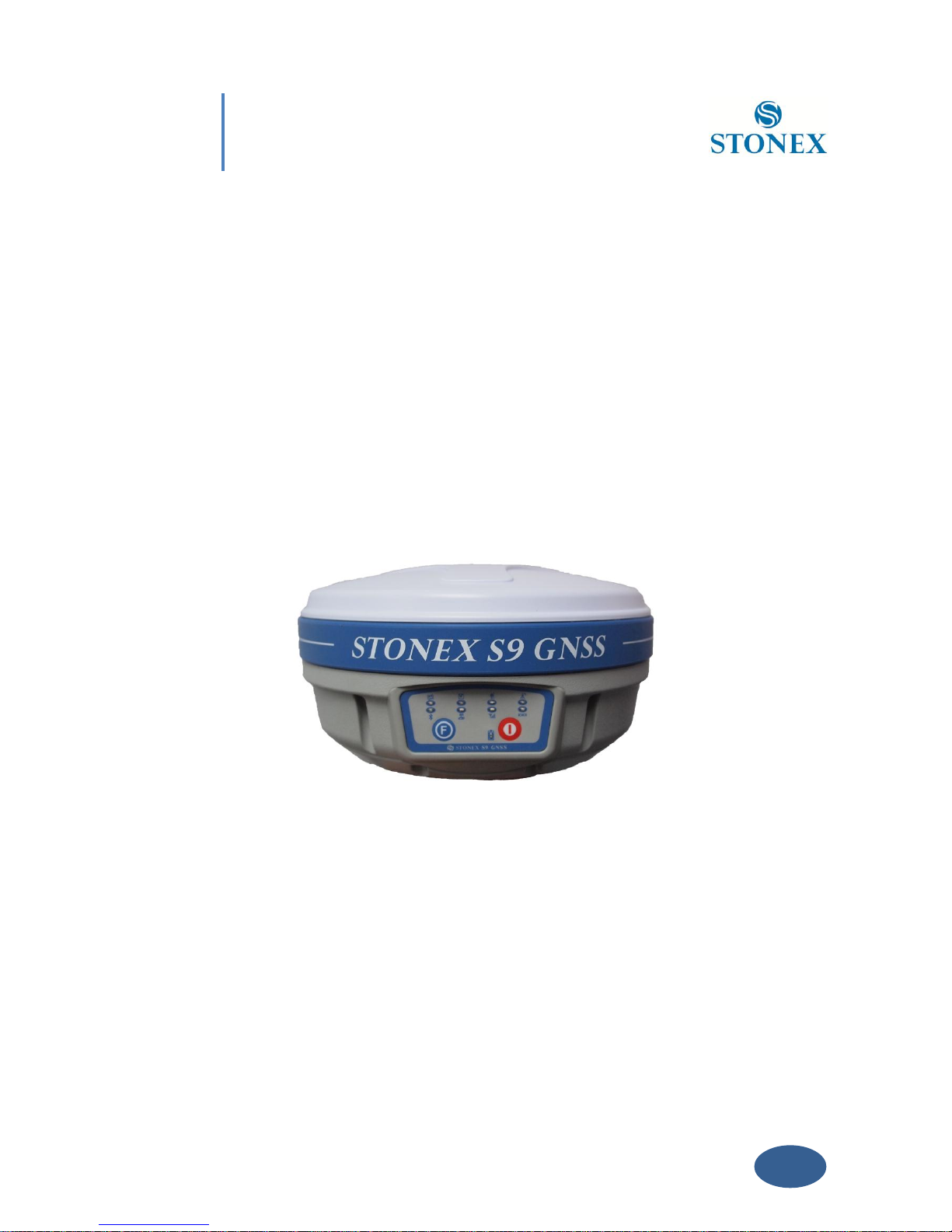
Chapter II: S9III mainframe
II.1 The outlook of mainframe
The mainframe has an almost cylindrical shape, with a base larger than the height. There are
three parts: an upper cap, a rubber loop and the main structure. The upper cap protects the
GNSS antenna placed inside. The rubber loop has the function of softening possible shocks or
falls. In the front of the main structure there are 2 keys and 9 lights, on the bottom side there is
one slot for the built-in radio and GSM/GPRS module, and one for the battery and SIM card. All
the others components of the receiver (Bluetooth device, main board, OEM board, etc.) are
contained inside the main structure.
Fig. 2.1 - S9III mainframe
II.2 Interfaces
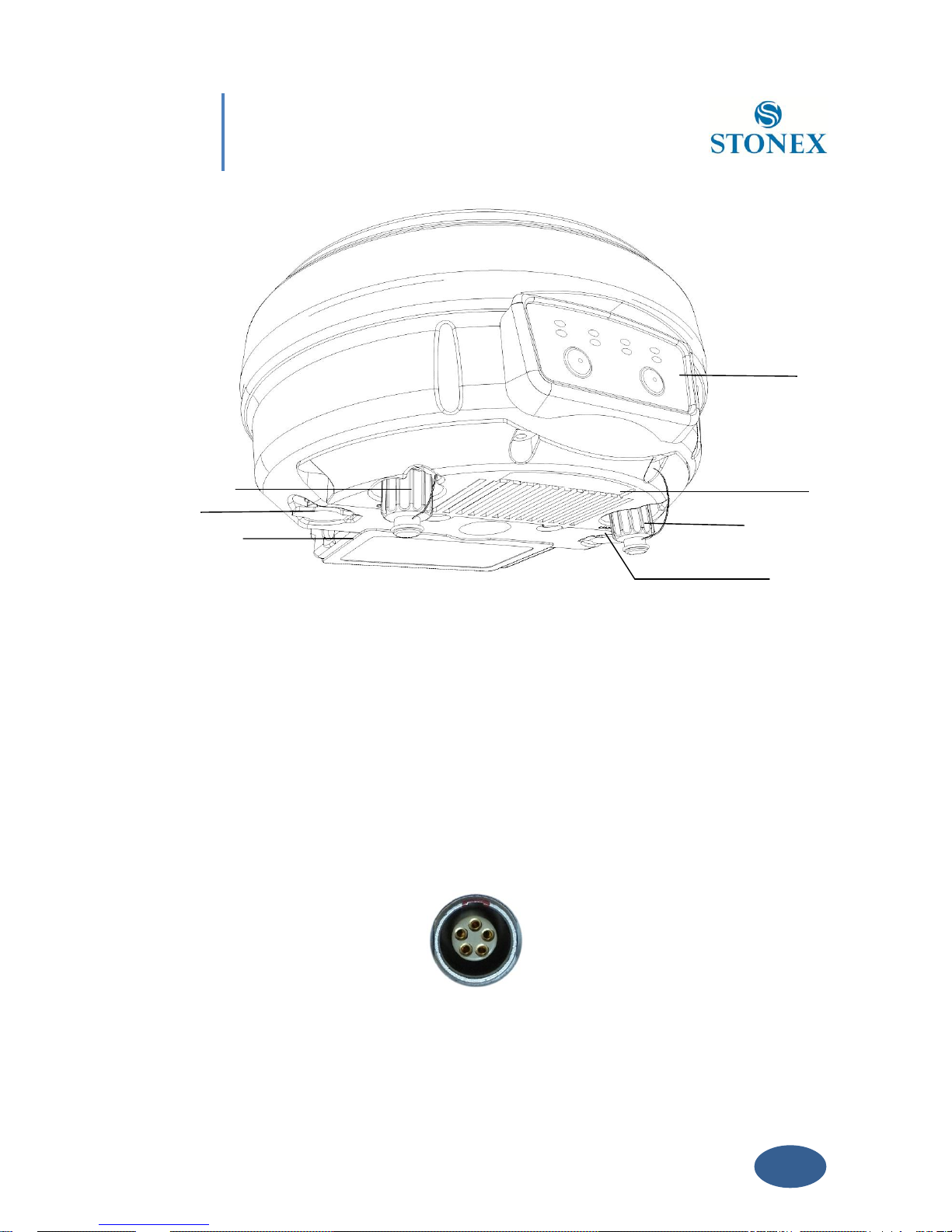
The mainframe interfaces are shown in Fig. 2.2: the left port (five pins LEMO) is used for
external power supply and external radio, the right port (seven pins LEMO) is used for data
transferring between receiver and computer or between receiver and the handheld. Near the
radio module there is the radio antenna interface.
Page 8
Chapter II: S9 III mainframe
7
a) TNC connector for GPRS/GSM antenna
b) 5pins Lemo port for external datalink connection
c) Battery housing
d) Front panel
e) Built-in radio module
f) 7pins Lemo port for data transfer.
g) TNC connector for UHF radio antenna
Fig. 2.2 - S9III components and ports
Fig. 2.3 - 5-pins LEMO port
a f c
de g
b
Page 9
Chapter II: S9 III mainframe
8
Fig. 2.4 - 7-pins port
II.3 The installation of battery
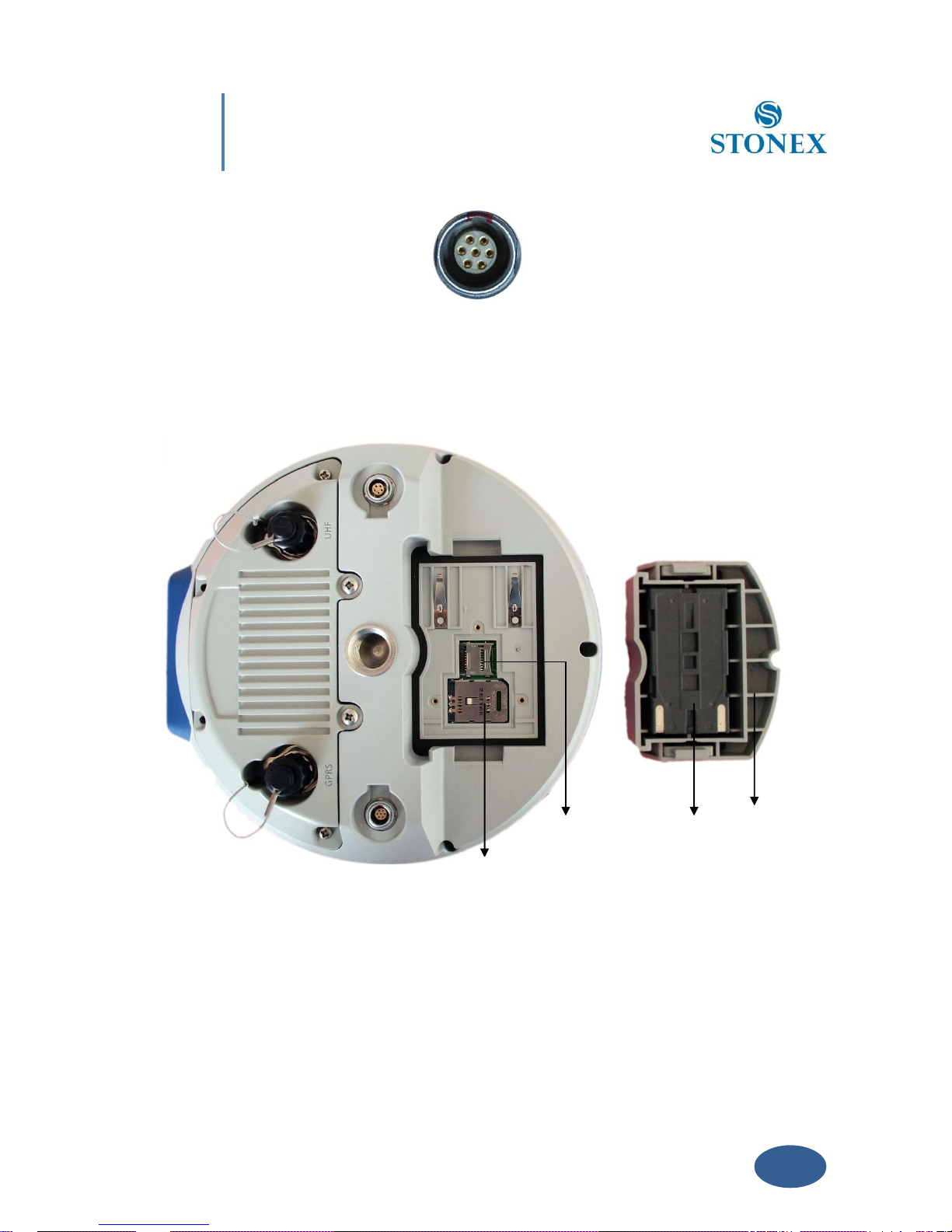
1. SIM card slot
2. MicroSD card slot
3. Battery
4. Battery housing
Fig. 2.5 - S9III battery housing
1
3 4 2
Page 10
Chapter II: S9 III mainframe
9
Under the place for the battery, there is a slot for SIM card, necessary when a connection by
GPRS/GSM is used.
II.4 Indicator leds and instrument setup
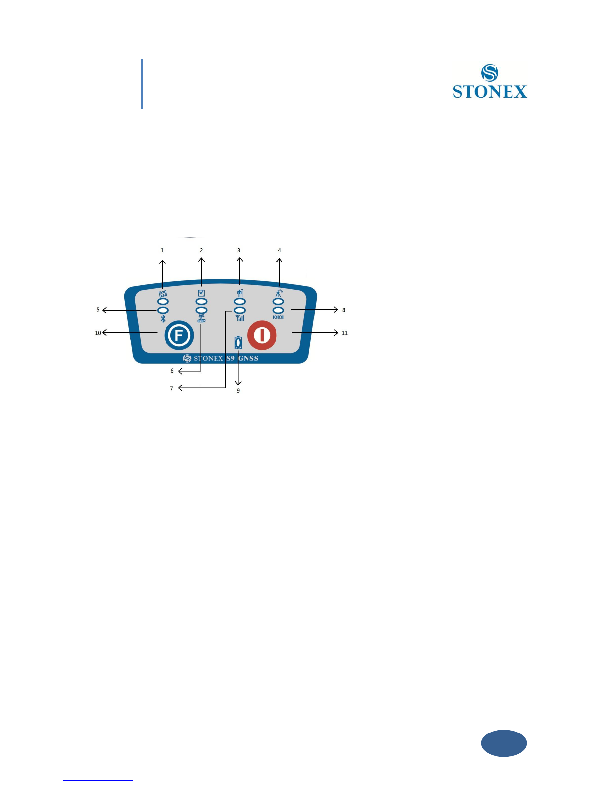
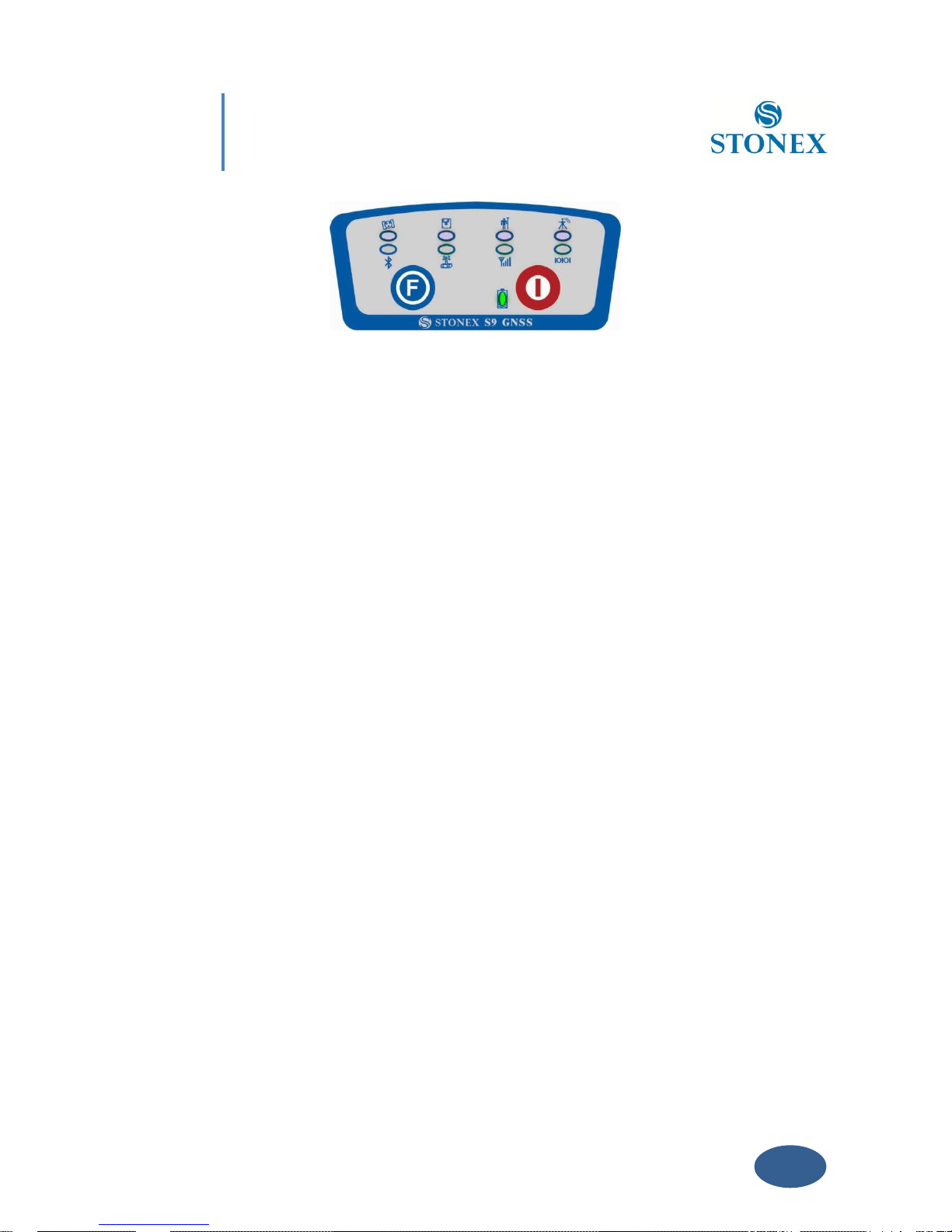
Fig. 2.6 - S9III keys and indicator leds
1. satellite led
2. static led
3. rover led
4. base led
5. Bluetooth led
6. internal radio led
7. GSM/GPRS led
8. external data link led
9. internal power led
10. Function Key
11. Power Key
The functionality as follows, from left to right:
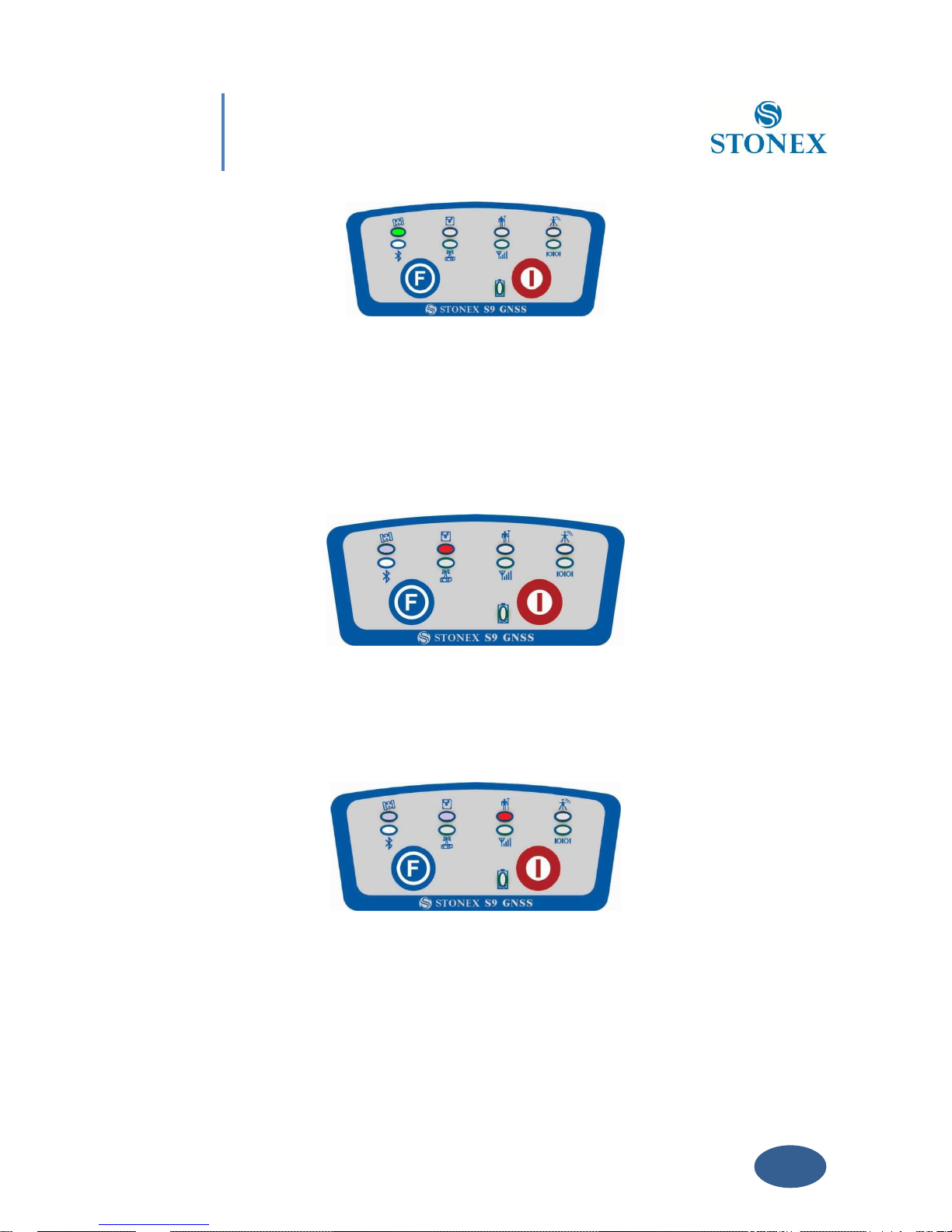
SATELLITE led (green):
It shows the amount of locked satellites; when the receiver links one or more satellites
signal, it will start to blink every 30 seconds for a number of times equal to the number
of locked satellites.
Page 11
Chapter II: S9 III mainframe
10
Fig. 2.7 - S9III satellite led
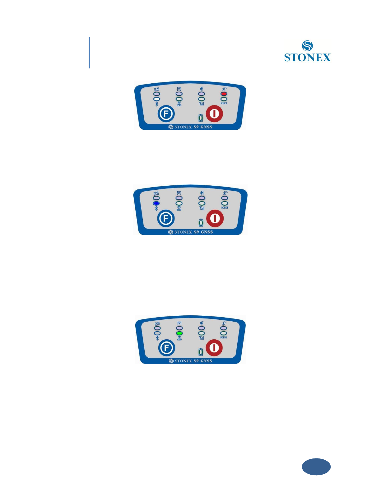
STATIC led (red):
It switch on if the static mode is selected and it starts to blinks when the receiver is
recording data, with the same frequency of the sample rate, if the sample rate is greater
than 1 Hz it blink anyway at 1 Hz.
Fig. 2.8 - S9III static led
ROVER led (red):
Rover led is on when the receiver is working in rover mode
Fig. 2.9 - S9III rover led
BASE led(red):
Base led is on when the receiver is working in base mode.
Page 12
Chapter II: S9 III mainframe
11
Fig. 2.10 - S9III base led
BLUETOOTH led (blue):
Once you have connected the receiver with the handheld, this led will switch on.
Fig 2.11 - S9III bluetooth led
INTERNAL RADIO led (green):
This led is on when UHF internal radio is selected as RTK datalink.
It is blinking when is transmitting data in base mode or receiving data in rover mode.
Fig 2.12 - S9III internal radio led
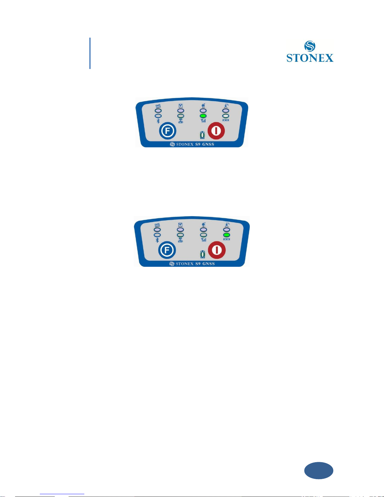
GSM/GPRS led (green):
This led is on when GSM/GPRS module is selected as RTK datalink. It starts to blink when
Page 13
Chapter II: S9 III mainframe
12
there is data transfer ongoing ( download in rover mode and upload in base mode).
Fig 2.13 - S9III gsm/gprs device led
EXTERNAL RADIO led (green):
This led is on when external datalink is selected as RTK datalink. It starts to blink when
there is data transfer ongoing( download in rover mode and upload in base mode).
Fig 2.14 - S9III external radio led
POWER led (green and red) :
It includes three kind of status:
1. Green: power supply in good condition.
2. Red: low power (below 20%).
3. Red blinking and beeping: very low power (below 10%)
Usually when the light becomes red you have still one hour of power reserve. External
power and internal battery share same power light. When external power is used, the
led indicates external power level.
Page 14
Chapter II: S9 III mainframe
13
Fig. 2.15 - S9III power led
F Key : Function key
It can switch the working mode (static, base or rover) and RTK datalink (built-in radio, external
radio or GPRS/GSM).
Switch working mode: Power on the receiver while pressing F key in the meantime, wait
until all lights flash, then release both buttons. Now every time you press F key, you will
see one red led switched on and moving through the three working mode.
Switch datalink: Press F key in ROVER or BASE mode, then release after the beep, you
will see one green led switched on, that moves every time you press F key through the
three datalink.
I Key: Power key
It powers on/off the receiver function and has a confirm function.
Power on receiver: Press and hold I key for at least one second, the receiver will power
on.
Power off
receiver: Press and hold I key for few seconds, after three beeps all lights turn off, at
that point release the key, the receiver is off .
Page 15
14
Chapter III: S9 III standard accessories
Chapter III: S9III standard accessories
On the basis of the configuration chosen (base or rover) some of these accessories are included
in the receiver bundle.
III.1 The case of S9III
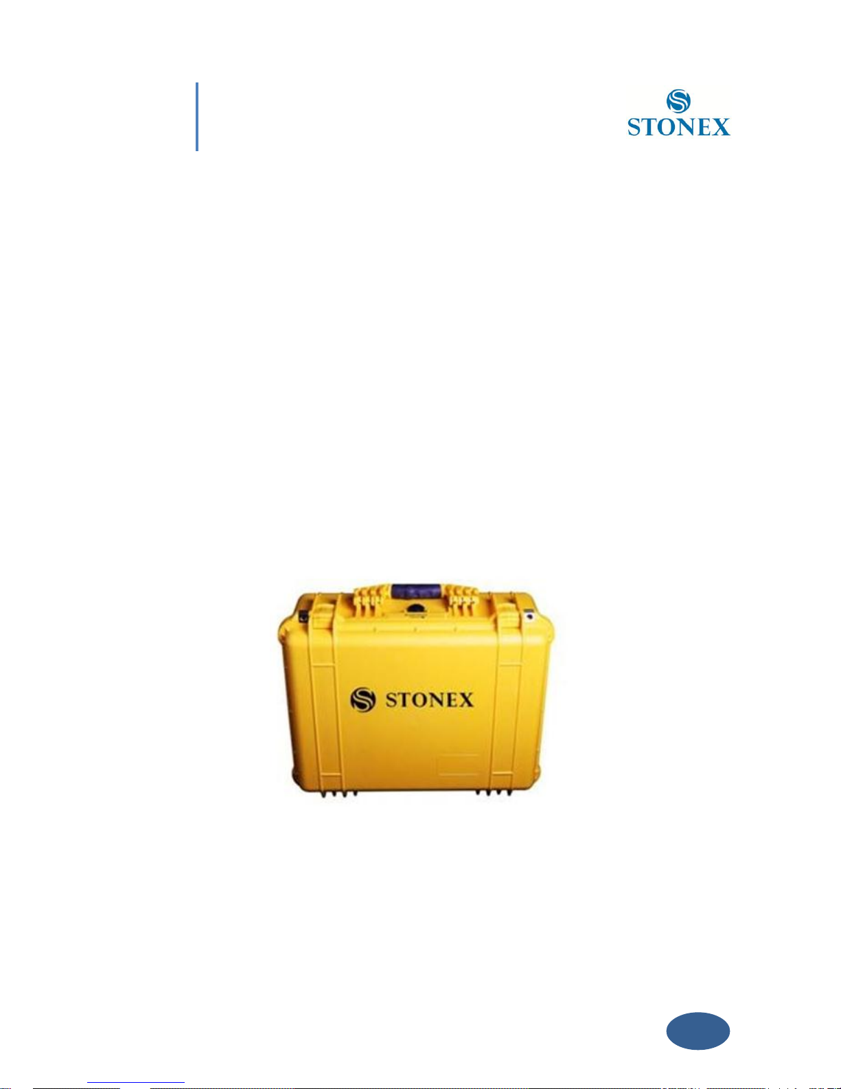
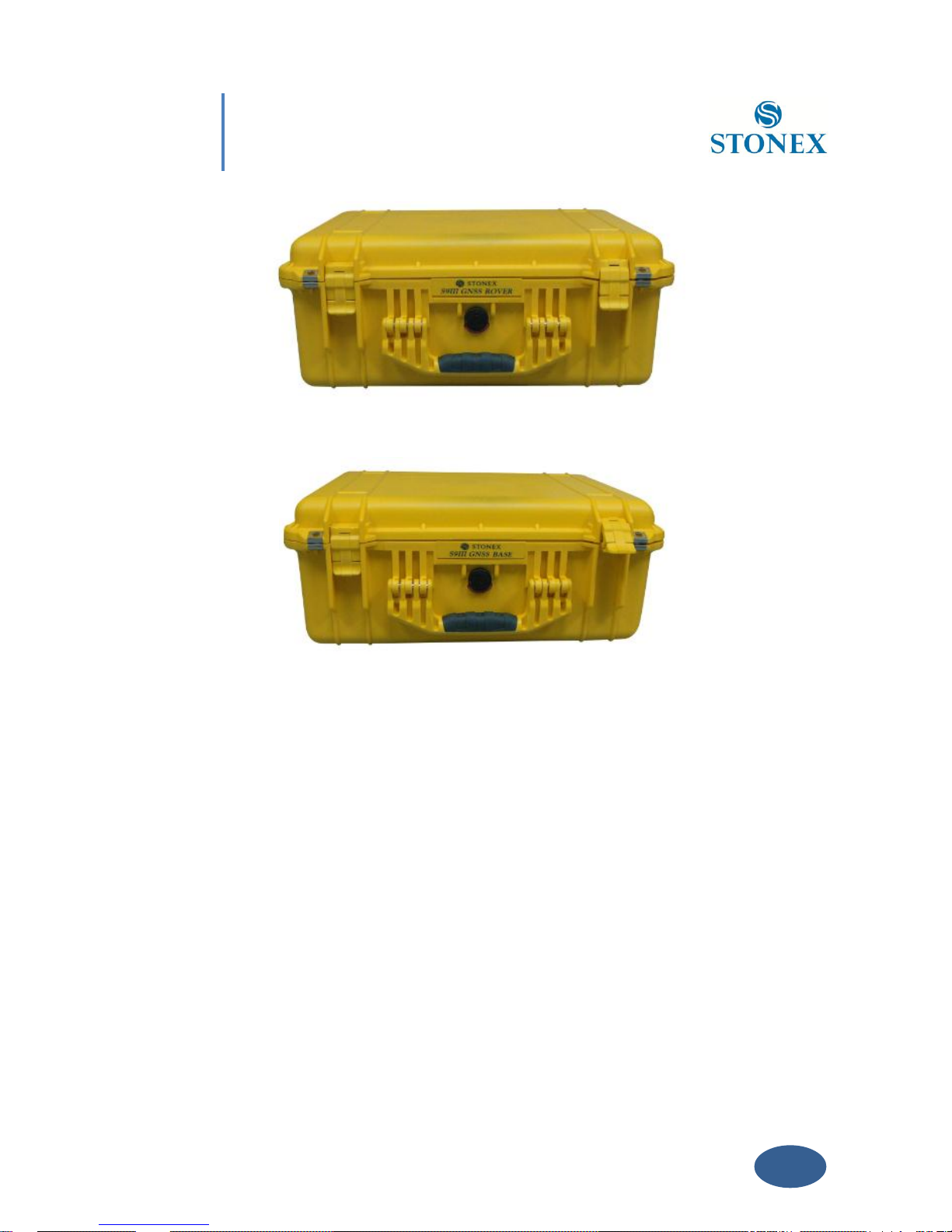
There are two kinds of S9III cases: Rover case and Base case. The inner layout of the Base case
and Rover case is different.
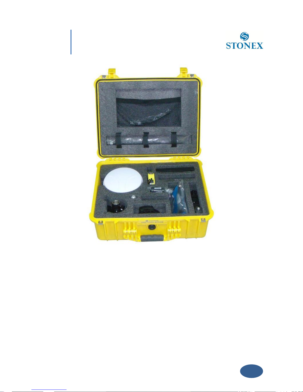
Base case contains also the basement and tribrach for fixing the base on a tripod and a 40 cm
pole for put the base higher, while Rover case included the bracket for the controller. You can
distinguish them from nameplate.
Fig. 3.1 - S9III case
Page 16
15
Chapter III: S9 III standard accessories
Fig. 3.2 - S9III Rover case
Fig. 3.3 - S9III Base case
Page 17
16
Chapter III: S9 III standard accessories
Fig. 3.4 - S9III internal case of Rover
III.2 Power supply
Batteries
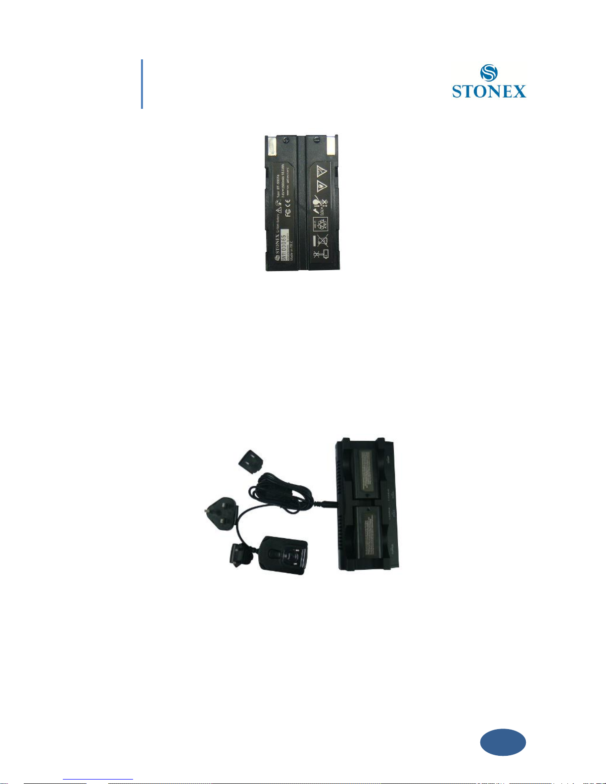
The standard configuration contains two batteries, a slot for charging batteries (named
“charger” for simplicity) and an adaptor. The battery are “lithium-ion” battery (7.4 V - 2500
mAH): a technology which has an higher energy-to-weight ratio with respect to NiCd or NiMh
batteries, no memory effect, and slow self-discharge when not in use.
Page 18
17
Chapter III: S9 III standard accessories
Fig. 3.5 - Lithium-ion battery
Charger
The charger can charge both batteries simultaneously. The lights of the charger shows if the
battery is being charged (red light CHARGE) or if it is already charged (green light FULL). Red
light POWER shows if the charger is powered on and there is also a light which turns on in case
of too high temperature (red light TEMP).
Fig. 3.6 - S9III charger and adaptor
III.3 The antennas
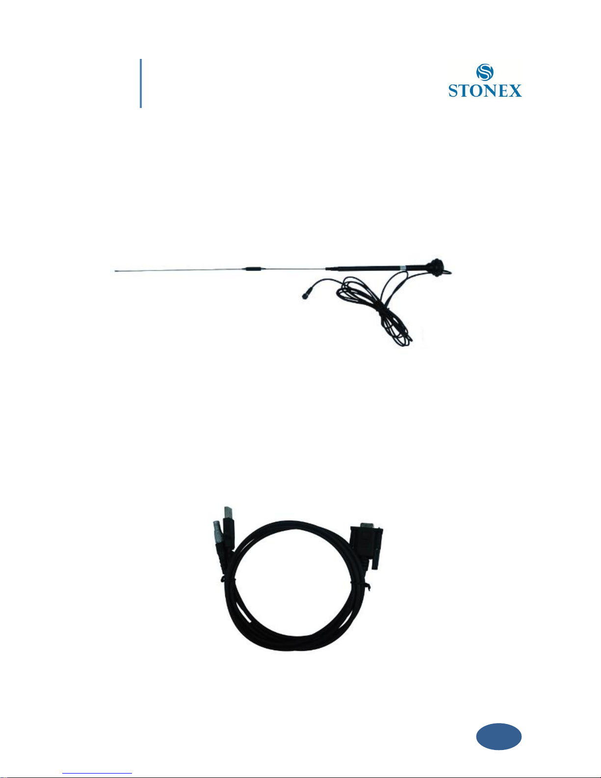
S9III adopts a UHF all-direction transmitting and receiving antenna. Since there are three
Page 19

18
Chapter III: S9 III standard accessories
different internal radio settings with different frequency range, the corresponding antennas
have different length. The available range are: 410-430 MHz, 430-450 MHz and 450-470 MHz.
the corresponding antennas have length of: 40, 37,5 and 34 cm. They are suitable for field
surveying, light and durable. The gain is 2.15 dBi.
Fig. 3.7 – built-in radio antenna (not in scale)
S9III adopts a GPRS/GSM all-direction transmitting and receiving antenna with a frequency in
the ranges 824-960 MHz and 1710-1880 MHz. It is suitable for field surveying, light and
durable, the length is about 20 cm, the gain is 2 dBi .
Fig. 3.8 – Gprs/gsm antenna (not in scale)
For S9III, it is possible to use like additional accessory (not included in the standard
Page 20
19
Chapter III: S9 III standard accessories
configuration) a high-gain UHF all-directional transmitting antenna for base setup. The
available ranges are: 410-430 MHz, 430-450 MHz and 450-470 MHz. The antenna is around 1
meter long and can be mounted on a retractable pole or a tripod for better performance. The
higher the antenna is, the larger cover area does it has for the radio signal. The gain of the
antenna is 5 dBi.
Fig. 3.9 –External radio antenna (not in scale)
III.4 Cables
Receiver standard cable
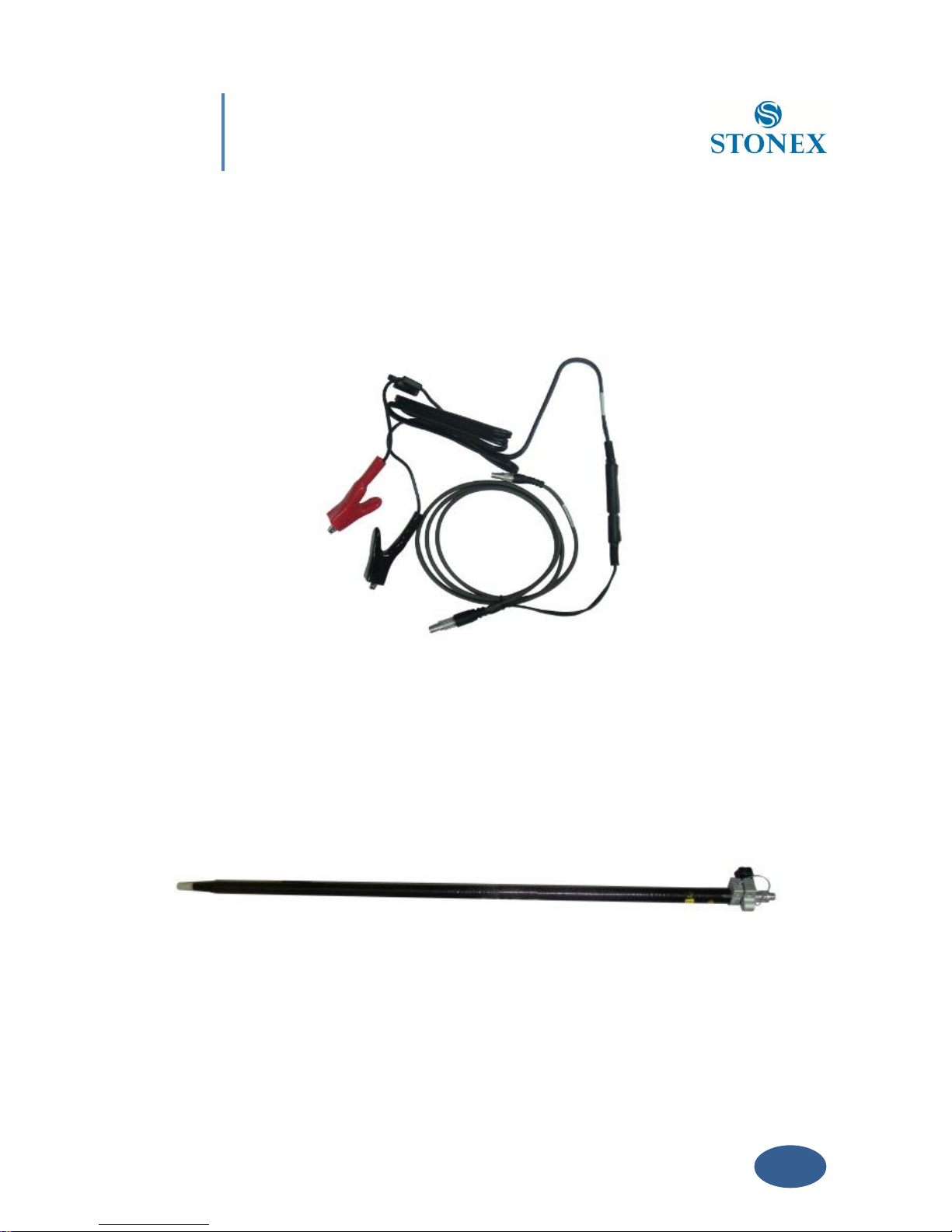
This is a multi-function communication cable: it is used for connecting receiver (by a 7-pins
LEMO port) and computer (by a serial and USB port) used for transferring the static data,
setting the receiver, updating the firmware and the license.
Page 21
20
Chapter III: S9 III standard accessories
Fig. 3.10 - Multi-function communication cable
Auxiliary cable
External power supply cables can be ordered and used to connect an external battery (red and
black clips) to the receiver (small 5-pin LEMO):
Fig. 3.11 - External power supply cables
III.5 Other accessories
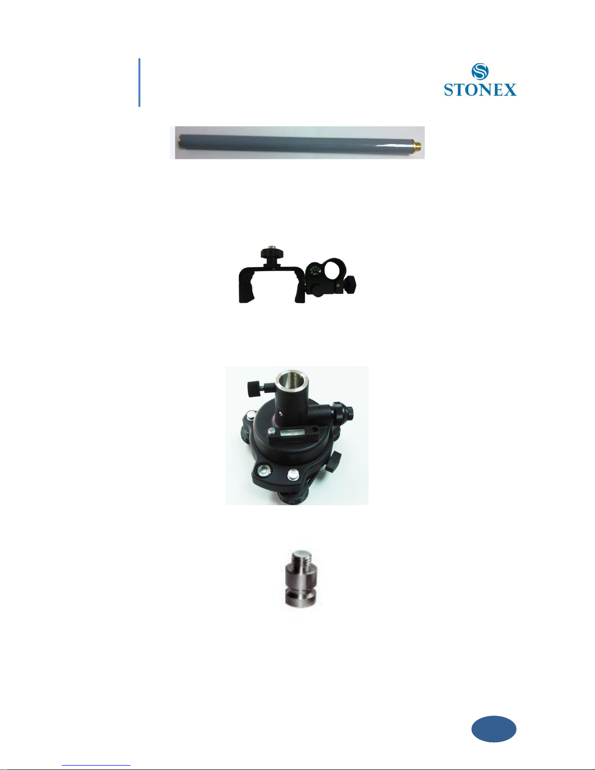
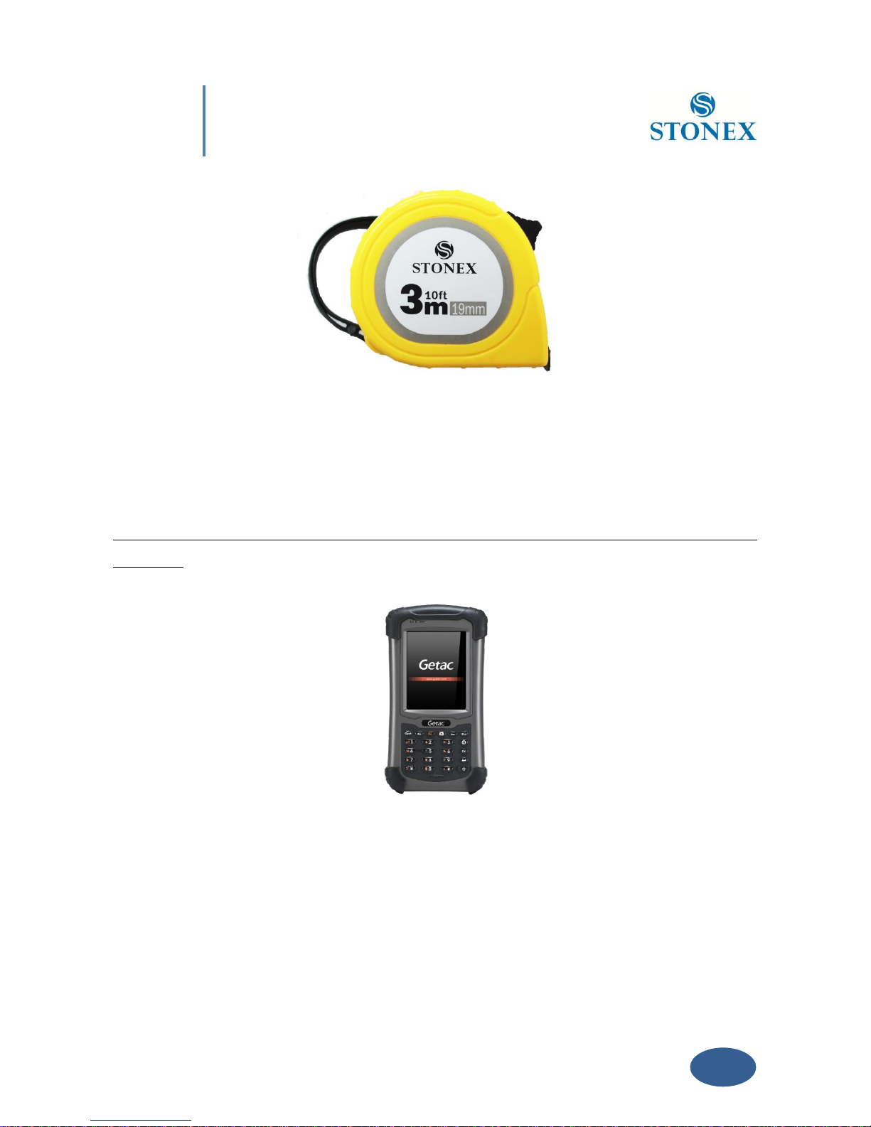
The other accessories are: 2.45 m retractable pole, 40 cm supporting pole, two kind of brackets
depending on the controller, tribrach with plummet, tripod (wood or aluminum, with quick or
twist clamps), connector between receiver and tribrach, and measuring tape.
Fig. 3.12 – 2.45m retractable pole
Page 22
21
Chapter III: S9 III standard accessories
Fig. 3.13 – 40cm supporting pole
Fig. 3.14 – Bracket B1 for Getac
Fig. 3.15 – Tribrach and adapter with optical plummet
Fig. 3.16 – Connector between tribrach and receiver
Page 23
22
Chapter III: S9 III standard accessories
Fig. 3.17 – Measuring tape .
III.6 Controller Getac PS236
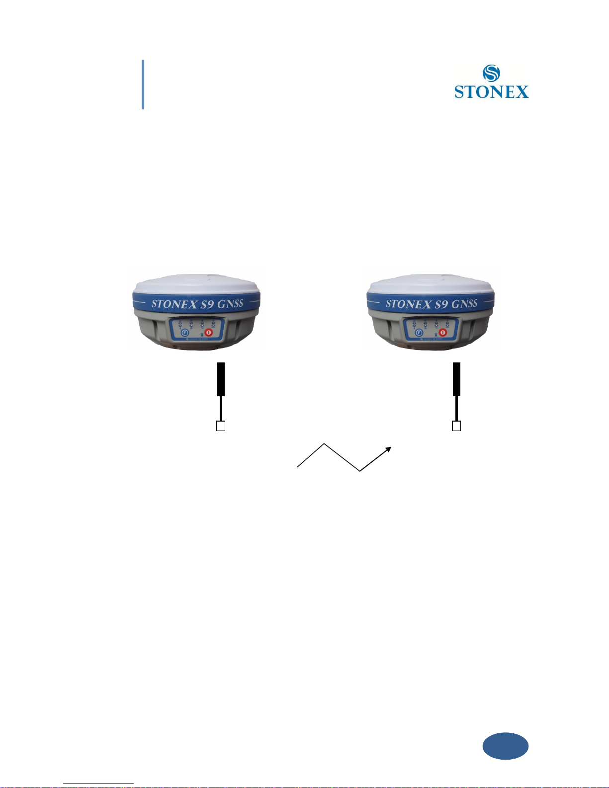
The S9III is usually provided with the Getac PS236 controller in the standard configuration.
Anyway the controller is not part of the accessories for S9III generation, it must be purchased
separately.
Fig. 3.18 - Getac PS236 controller
Page 24
23
Chapter IV: S9 III configuration
Chapter IV: S9III Configuration
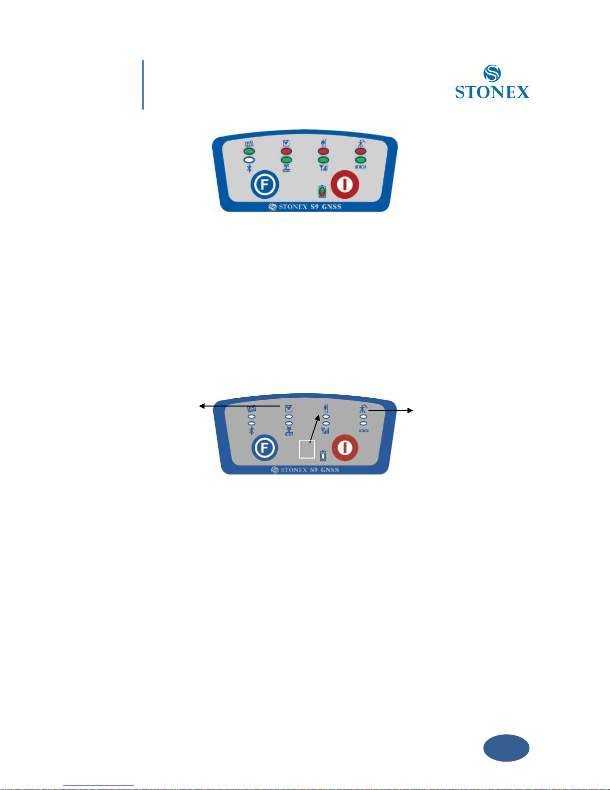
IV.1 The installation of base and rover
BASE ROVER
TX / RX ANTENNA TX / RX ANTENNA
Fig. 4.1 - Base and rover configuration
Installation of Base
- Install the tripod on the chosen location, level it and attach the receiver into tribrach.
- Attach the transmitting radio antenna into the port “UHF”: using the 40cm supporting
pole is better, since increases the height of the antenna. If you are using a direct GSM
connection you should attach the gsm antenna into “GPRS” port.
- Switch on the receiver and check the working mode. If it is not correct, please see next
paragraph IV.2 for understanding how to select the correct working mode or you can
Page 25

24
Chapter IV: S9 III configuration
change it later using the handheld software.
- Switch on the handheld and start the software for the radio channel configuration and
inserting the base coordinates, otherwise it is possible to make the settings by Stonex
Assistant pc software.
Installation of Rover
- Fix the bracket on the pole, fix the handheld into the bracket, put the rover on the pole
and attach receiving radio antenna into the port “UHF” or gsm antenna into the port
“GPRS”, depending on the connection used.
- Power on the receiver and check the working mode. If it is not correct, please see next
paragraph IV.2 for understanding how to select the correct working mode or you can
change it later using the handheld software.
- Switch on the handheld and start the software, then you can do the advanced setting of
the instrument and finally start the survey.
If you want to take very accurate measures (around or below cm accuracy), we recommend
you to use another tripod also for the rover.
IV.2 The configuration by using keys
How can you select the working mode?
- Insert the battery in the battery box, then press and hold I key + F key: the receiver will
start.
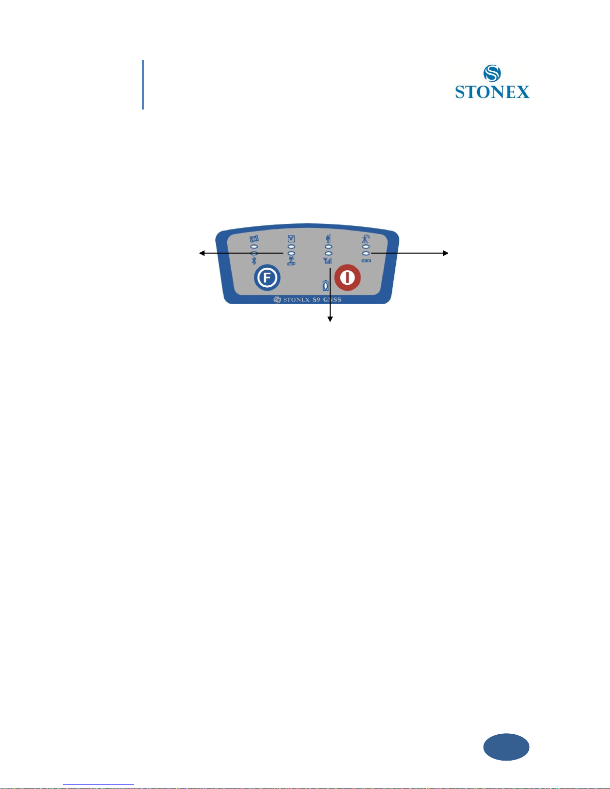
- Keep pressed I key + F key until all lights blink at the same time (Fig. 4.2), then release
the keys.
Page 26
25
Chapter IV: S9 III configuration
Fig. 4.2 - S9III, all led blinking at the same time
- Now every time you press F key, the STATIC/ROVER/BASE lights will switch on in the
corresponding order. You can select three different red lights, each of them refers to one
working mode.
- Press I key when the chosen light is blinking and the receiver will start in the selected
working mode . Summary of working modes:
1. Static mode
2. Rover mode
3. Base mode
Fig. 4.3 - S9III summary of working mode led
How can you select data link?
- After you entered working mode, press and release F key, the UHF/GPRS/EXT lights will
blink by turns at every pressure of F key. Then you can select different green lights, each
1
2
3
Page 27
26
Chapter IV: S9 III configuration
one refers to different data link. This situation refers only to the rover and base mode,
since in static mode there is no green light blinking.
- Press I key when the chosen light is blinking and the receiver will start in the selected
working mode. Summary of data link types:
4. Internal UHF Radio
5. GPRS\GSM module
6. External radio
Fig. 4.4 - S9III summary of data-link led
The next time you will switch on again the receiver, the working mode and data-link will be the
last selected.
If you prefer, you can select the correct data-link by handheld software.
As regards the advanced working parameters, for instance sampling interval, minimum
elevation angle, antenna height, etc, they can be set by handheld software or by Assistant,
without modifying the parameters the receiver will work with default parameters.
The static mode parameters cannot be selected by the controller, but only by Assistant.
IV.3 Standard operation of leds
Static mode
The STATIC and power led will keep lighted. When satellites fulfill the conditions (at least 4 GPS
or 4 GLONASS satellite), receiver will start recording epochs, you will hear a beep, STATIC light
6 5 4
Page 28

27
Chapter IV: S9 III configuration
will flash according to sampling interval (if you don’t set up, the default is 5 seconds) and the
satellite light will flash a number of times equal to the locked satellites.
Base mode
The BASE, power led and selected datalink (UHF, GPRS/GSM or EXTERNAL) will keep lighted.
When satellites fulfill the conditions, the base will enter into the transmit mode and start to
send data through the datalink. The datalink green led flashing every one second means the
base transmit normal. The satellite light will blink according to the number of satellites as
described for static mode.
Rover mode
The ROVER, power led and selected datalink (UHF, GPRS/GSM or EXTERNAL) will keep lighted.
The datalink green led flashing every one second means the rover is receiving data packets. The
satellite light will blink according to the number of satellites as described for static mode.
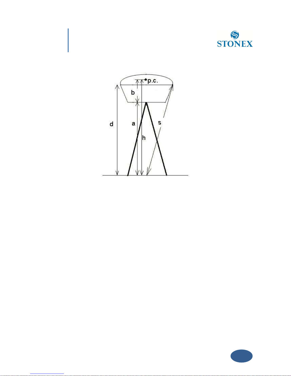
IV.4 How to measure the antenna height
The height of receiver is 99mm, the diameter is 186mm, the height from the center of the
sealed rubber ring to the bottom is 62mm.
The antenna height is conventionally defined as the vertical height from the phase centre to the
ground surveyed point (the distance “h” in fig. 4.5). It is not possible to measure it directly: you
have to measure other reachable heights (the distances “a”, “d”, “s” in fig.4.5). The distance “a” is
the vertical height from the ground to the mainframe’s bottom, “d” is the vertical height from
the ground to the middle of the rubber ring: both are defined as “vertical heights”. On the
contrary the distance “s” is measured from the ground surveyed point to the middle of the
rubber ring and is called “slant height”. You have to choose the measuring method according to
the used software.
Page 29
28
Chapter IV: S9 III configuration
Fig. 4.5 - Different measures of the antenna height
1. In rover and base mode you have to insert the correct antenna height according to RTK
software. In STONEX® SurvCE , for example, the distances “a” and “s” are permitted: software
will add the distance “b” to “a” (or convert “s”) to obtain “h”. For other software please read the
specific user guide.
2. In static mode you have to write the correct antenna height in .DAT or RINEX file. If you are
using STONEX® GPS Processor you have to specify the correct antenna height before processing
.DAT data or exporting it into RINEX format. The same if you are using STONEX® Assistant for
converting .DAT into RINEX. Please read the specific manual of STONEX® GPS Processor, it
should be noted that however the slant height “s” corresponds to the definition “Line of Edge of
antenna”, “a” to “Bottom of antenna” and “d” is equal to “Bottom of antenna mount”.
Page 30
29
Chapter IV: S9 III configuration
IV.5 How to download static data
For a correct connection between receiver and PC, follow the procedure described below. By
using a different procedure it may be very difficult to make a connection.
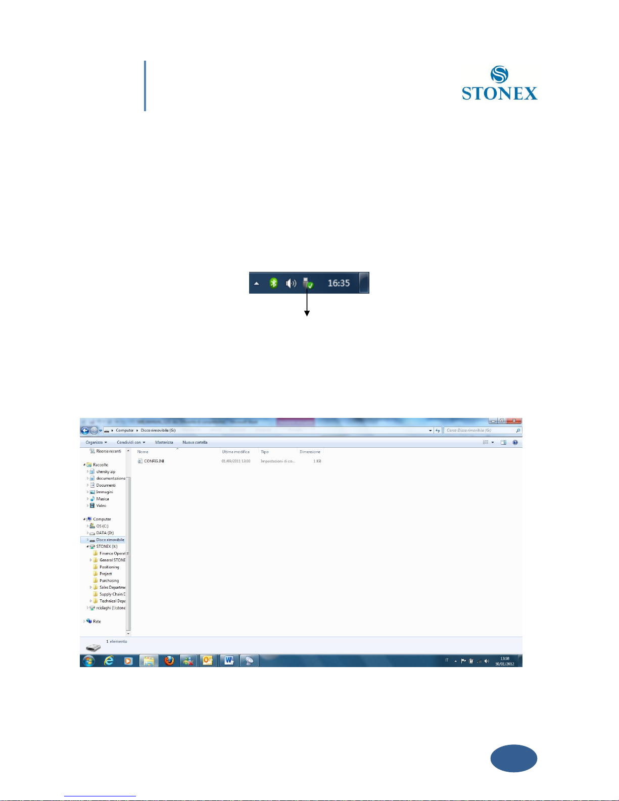
At first turn on the mainframe, then connect the cable to the communication interface of the
receiver (7-pins Lemo port), then insert the USB port in the PC. The taskbar will show as
follows:
Fig. 4.6 - Taskbar of windows including the receiver
The PC considers the receiver as a “removable disk”, so open the “removable disk”, and then you
can get the data files in the memory.
icon
Page 31

30
Chapter IV: S9 III configuration
Fig. 4.7 - Example of receiver files
You can copy the original file to PC and if necessary modify the file names. As Fig. 4.7, for
example, shows, .INI file is the configuration file stored in the memory of S9III. You can open
also the “CONFIG.INI” file as a simple text file and set some parameters of static mode: sampling
frequency, minimum elevation angle, etc. Please modify this parameters with care and don’t
change any parameter which is not clear because you could compromise the correct working
of the receivers.
You can use the STONEX® Assistant to download the raw data and set the parameters in a safer
way, as explained in Chapter V.
IV.6 Registration of the receiver
If the provisional license expired, you need to insert a new license code in the receiver for
continuing to use it. The license is composed of a 32 characters code. For inserting the new
license you can use RTK software STONEX® SurvCE: you have to enter into the submenu
“Equipment” “GPS utilities” “Send command”, then write the command
“SET,DEVICE.REGI,[license code]”.
However it is also possible to register the receiver using the STONEX® Assistant , as explained
in Chapter V.
Page 32
31
Chapter V: Stonex Assistant for S9III
Chapter V: STONEX
®
Assistant for S9III
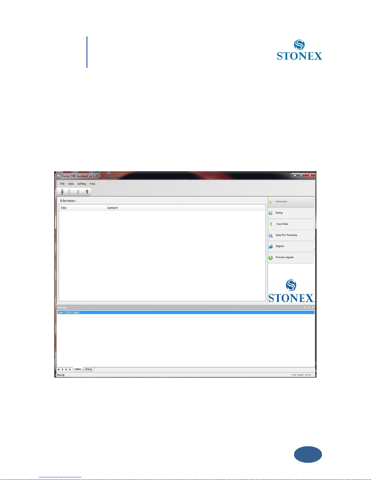
STONEX® Assistant is a tool which is conceived for aiding the user to make easier different
operations with the receiver S9III. It is contained in the bundle CD.
Fig. 5.1 – Main page of Stonex Assistant
Page 33
32
Chapter V: Stonex Assistant for S9III
The opening page, is showed in Fig. 5.1. It reports internal system configuration of the GPS
receiver S9 after get PC connection.
V. 1 Start Stonex Assistant on your PC.
Connect the S9 to the PC USB port using Lemo7 – USB/Serial cable.
Switch on the receiver; automatically the program should search the COM port where the
receiver is connected (automatic search works only for USB virtual serial connection). If this
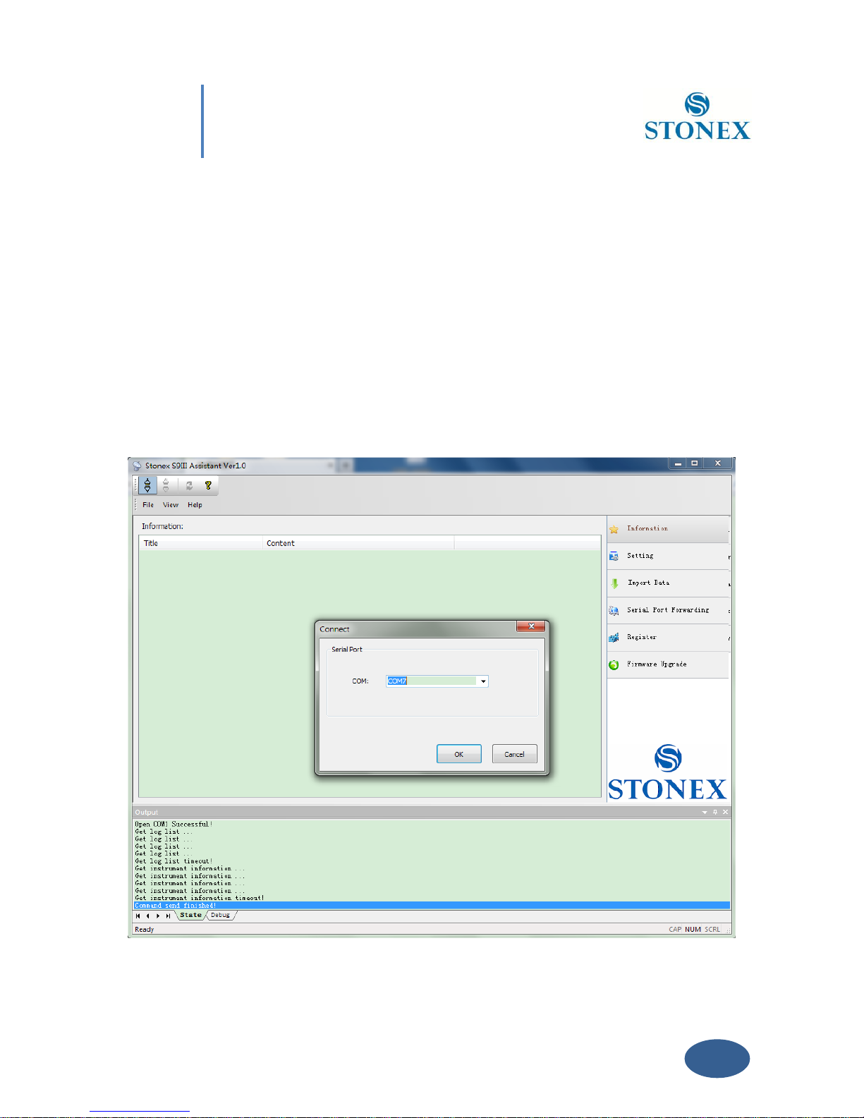
doesn’t happen, select the right COM port manually. To select the right COM port manually,
please click on “File”“Connect“ and you will get the Connect page, see Fig 5.2:
Page 34
33
Chapter V: Stonex Assistant for S9III
Fig. 5.2 - Opening COM port
Try to get connection inserting different COM number (like COM1, COM2, etc), and then select
“OK” button. When you have find the right COM port, you should see the screen shown in Fig
5.3 that show you in the main window the system information.
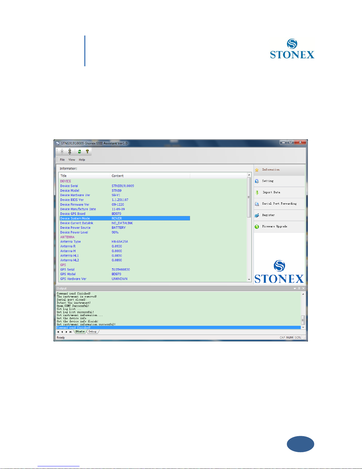
Fig. 5.3 – Information page of Stonex Assistant
From the showed information you can understand about: the battery level, the firmware
version of GNSS board, the antenna information, the firmware of radio and gprs internal
device, the free disk space and the current working and datalink setting.
Page 35
34
Chapter V: Stonex Assistant for S9III
V. 2 Setting
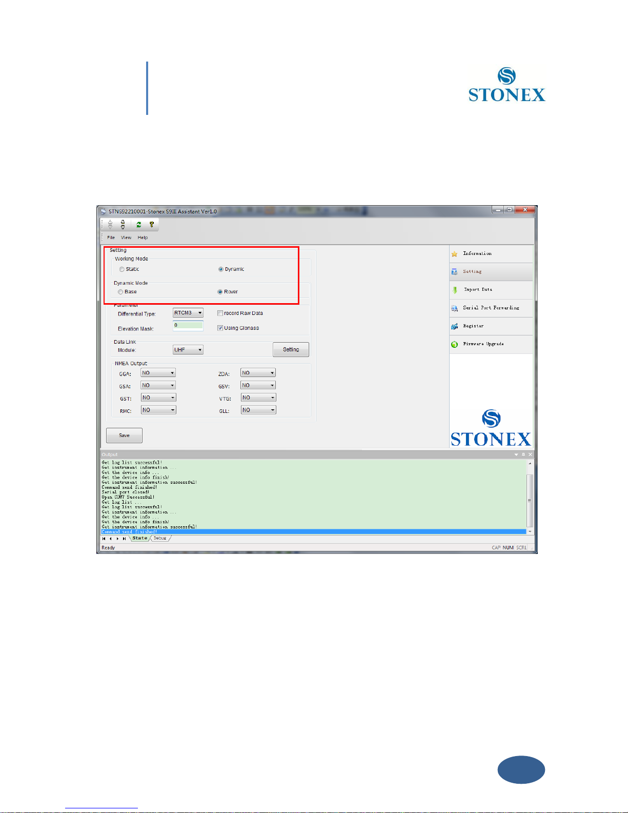
If you click on the menu “Setting ” on right, a new menu window is opening as in Fig. 5.4.
Fig. 5.4 – Setting window
From this window you can set the most important parameters of the receiver without opening
the CONFIG .INI file and modifying it by hand in a text editor.
You can set the survey working mode (Static, Dynamic - Base/Rover) and kind of datalink
(NETWORK, UHF, EXTERNAL, BLUETOOTH) of S9III (see the red rectangle in Fig. 5.4).
Some definitions of working mode:
Page 36

35
Chapter V: Stonex Assistant for S9III
Static: is the stand-alone station that collect raw observations and need a post-processing in
office for getting accurate results.
Base: is the fixed GPS station used to provide differential corrections to the mobile GPS receiver.
Rover: is the mobile receiver used to survey on field.
Some definitions of available datalink:
Network: is an internet connection by GPRS band to a base that provide differential corrections
or a connection between base and rover by a GSM direct call (like a phone call)
UHF: is a connection between base and rover by the internal radio communication.
External: is a connection between base and rover by an external device attached through the 5-
pin LEMO port, it is usually an external radio.
Bluetooth: is an option for sending or receiving the NTRIP corrections to the receiver through
the Bluetooth channel.
Select “Static” for a static survey operation, “Dynamic” if you want to do RTK measures with
your S9III.
V. 2.1. Static Data Survey
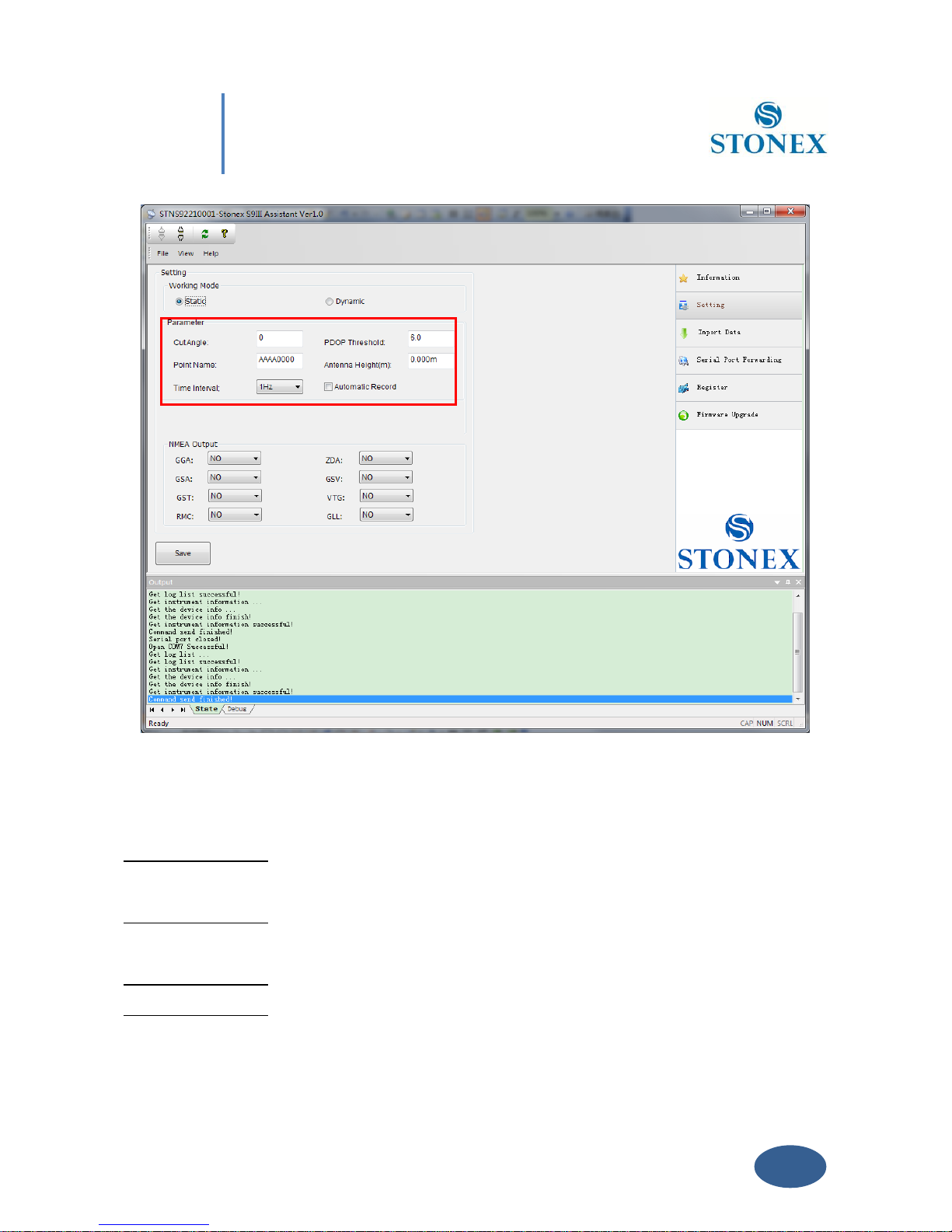
Static mode data entry page is reported on Fig 5.5:
Page 37
36
Chapter V: Stonex Assistant for S9III
Fig. 5.5 – Static working mode
From here you can control following data settings:
Cut Angle : Define the minimum elevation of satellite to be collected in order to avoid
noisy satellites (suggested value between 15° and 10°).
PDOP Threshold : Define the maximum value of PDOP for valid GPS data in order to avoid
bad satellite configuration in the sky (suggested value below 3).
Point Name : Assign a “name” to the point you are surveying.
Antenna Height : Introduce GPS antenna height from ground, see Par IV.5 .
Page 38

37
Chapter V: Stonex Assistant for S9III
Time Interval : Set sampling frequency between different GPS epochs.
Automatic Record : Start automatic GPS static survey after power on. For static survey this
option strictly NEED to be checked in Stonex PC Assistant.
When the configuration is completed, click on button “Save” to update the Receiver
configuration.
V. 2.2. Dynamic working mode
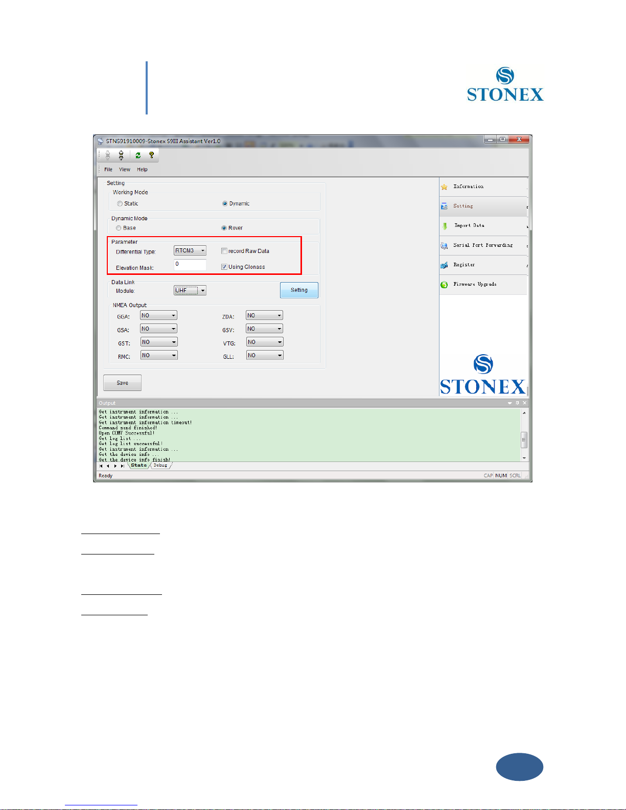
In the Dynamic working mode (Rover or Base) the following parameters should be specified, as
you can see in Fig. 5.6.
Page 39
38
Chapter V: Stonex Assistant for S9III
Fig. 5.6 – Dynamic working mode parameters
Differential type: To select the format of the differential corrections transmitted or received.
Elevation mask: Define the minimum elevation of used satellite to be collected in order to avoid
noisy satellites (suggested value between 15° and 10°).
Record Raw data: to record raw data inside memory of S9III.
Using Glonass: to enable/disable Glonass reception.
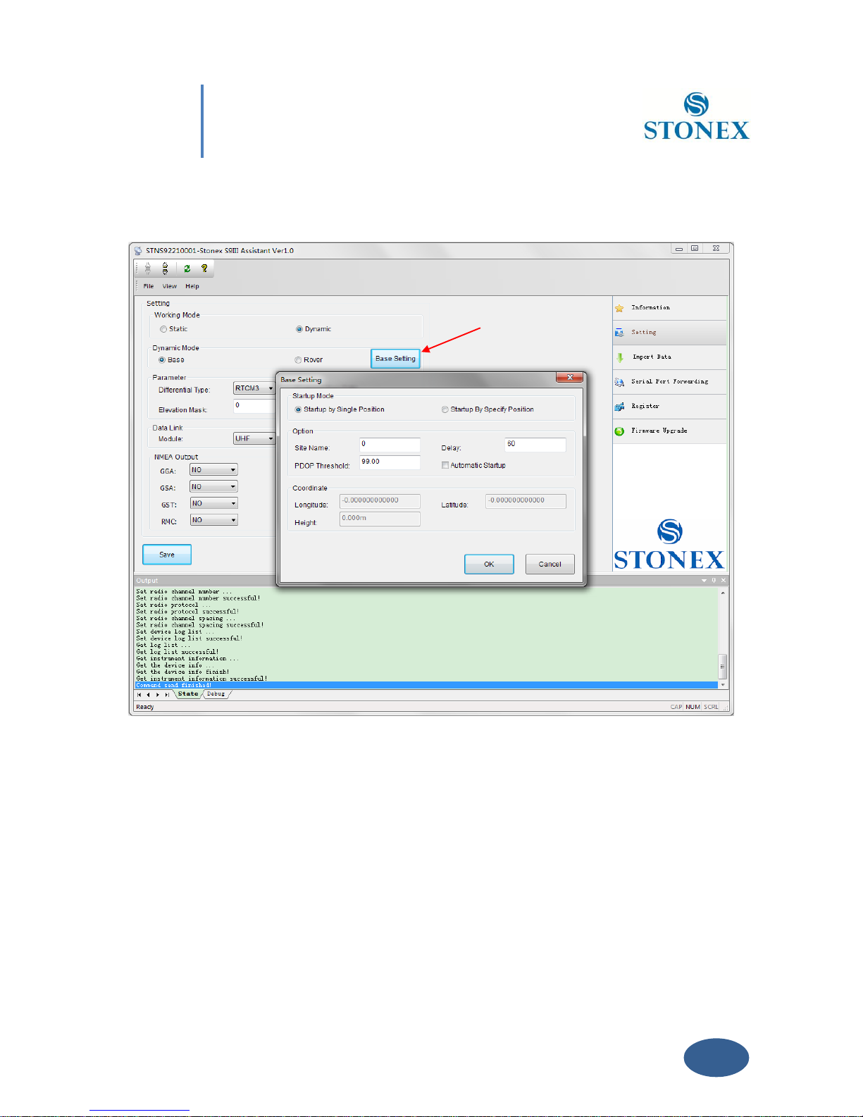
V. 2.2.1. Base coordinates setting
If you choose “Dynamic” and “Base” option, a “Base Setting“ button will appear on the screen,
Page 40
39
Chapter V: Stonex Assistant for S9III
see red arrow in Fig. 5.7. Click on it, and the Base Setting module will appears on the screen:
Fig. 5.7 – Base Setting window
Inside this form, you can choose if the Base coordinates must be inserted manually ( “Start Up
By Specific Position” ) if known, or calculated from GPS observations ( Automatic Start Up By
Single Position) if unknown.
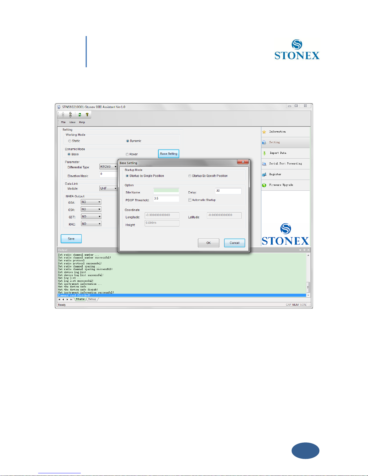
Automatic Start Up By Single Position
If checkbox “Automatic Start Up“ is selected, the GPS Receiver will calculate the geographical
coordinates of the base using an average value from GPS observations. The time delay after
Page 41
40
Chapter V: Stonex Assistant for S9III
switch on for base transmission must be inserted in the Text Box “Delay“.
Fig. 5.8 – Automatic Start Up By Single Position
Click “OK” to confirm your data entry.
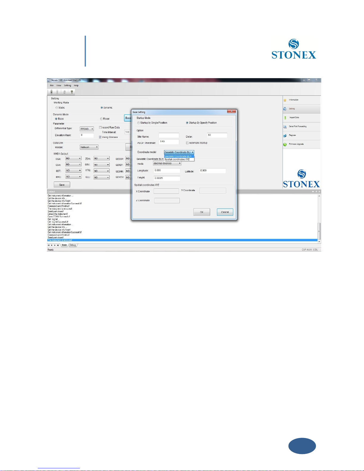
Start Up By a Specific Position:
By choosing the “Start Up by Specific Position” it is possible to introduce directly the
geographical coordinates of the base (Known point): you can insert also geocentric X,Y,Z.
Page 42
41
Chapter V: Stonex Assistant for S9III
Fig. 5.9 – Start Up by a specific position
V. 2.3. Data Link
Here you can select the type of datalink used to get/provide differential corrections.
Four different options are available for “rover” mode, while three options for “base” mode
(network, internal or external radio).
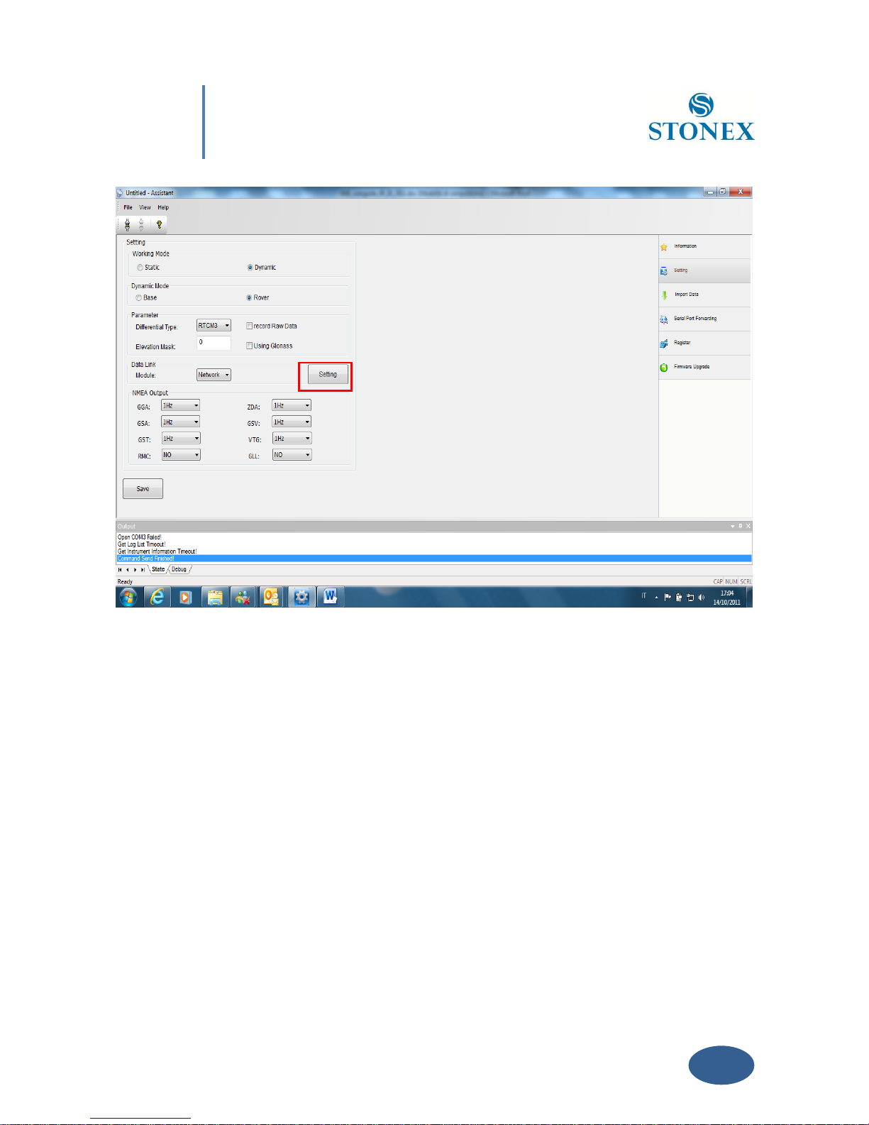
V. 2.3.1 Network
This option is relative to get GNSS differential corrections from a CORS system.
Page 43
42
Chapter V: Stonex Assistant for S9III
Fig. 5.10 – Network
If you will click on the button “Settings” (red rectangle in Figure 5.10), a new form will open.
From here you can choose the type of connection:
Page 44
43
Chapter V: Stonex Assistant for S9III
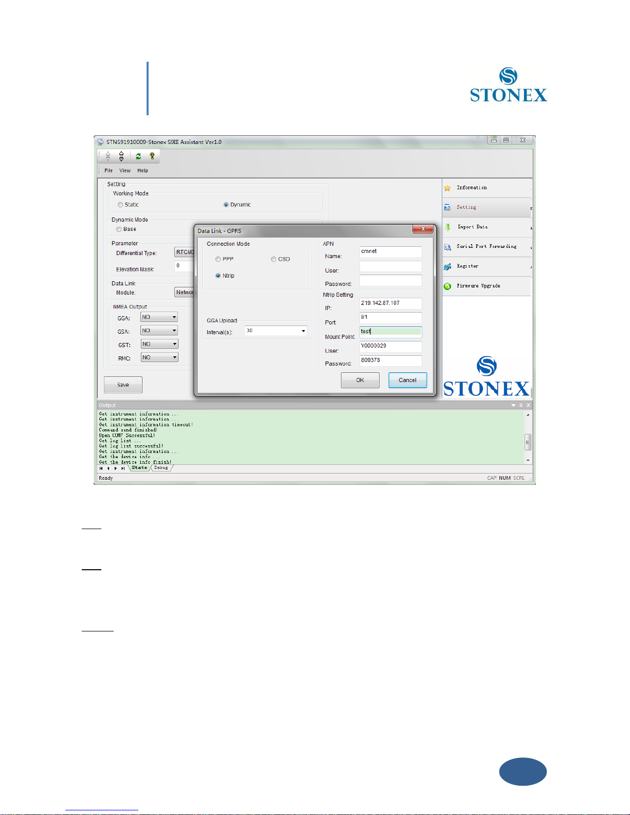
Fig. 5.11 – Network menu’
CSD: Normal dial GSM call, using a phone number that you can insert in “Base Number“ Text
Box.
PPP: For VPN (Virtual Private Network) users only. For VPN uses, each SIM card has assigned a
static IP address. Therefore the rover can be connected directly to the base via entering the
base IP.
NTRIP: It is the most common. Connection to a provider using data transfer in accord with
NTRIP protocol by internet GPRS connection. If you will select this option, the right side of the
form (APN menu) will be activated, and from here you can insert data like:
Page 45

44
Chapter V: Stonex Assistant for S9III
a) Name of APN provider provider of the RF Network connection.
b) User and Password (normally not required).
c) NTRIP setting parameters like IP address of CORS provider, Port Address, Type
of Mount Point, User Name and Password of the user.
The “GGA Upload” input windows provide the interval of NMEA GGA string upload, this string
contains the rover coordinates that must be sent to the CORS or base.
Click on “OK” button to confirm your entry.
V. 2.3.2 UHF Radio
Choose this option when you are taking differential corrections from your GPS Base.
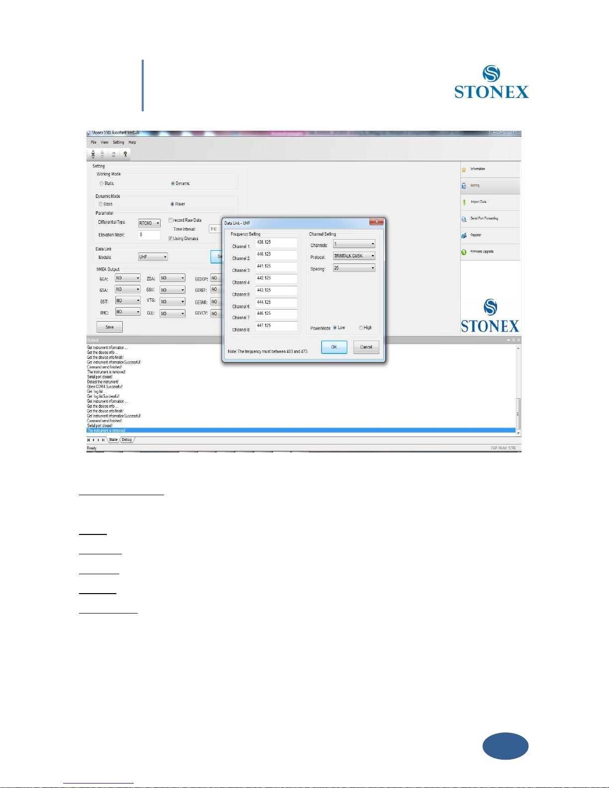
If you select UHF from the Scroll box and click the “Setting” Button a new form will open,
where you can introduce following data: Frequency settings, Station name, Channel number,
Protocol and Channel Spacing , as you can see in Fig 5.12.
Page 46
45
Chapter V: Stonex Assistant for S9III
Fig. 5.12 - UHF Radio Settings
Frequency setting: insert the frequency, expressed in Mhz, of the radio link associated to each
channel .There are 8 channels available in the internal UHF radio .
Name: You can associate a name to each Radio.
Channels: Selected the “default” Radio channel active after power on .
Protocol: Select the type of Radio protocol. For internal Radio, Select TrimTalk GMSK.
Spacing: Select Minimum Channel Spacing ( use 25KHZ like default ).
Power mode: Select the transmission power level low (0,5 Watt) or high (1 Watt).
Click on button “OK” to confirm your choice.
Page 47
46
Chapter V: Stonex Assistant for S9III
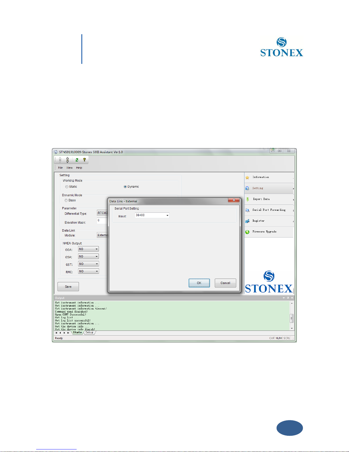
V. 2.3.3 External
This option give us the possibility to use an external device, usually an external UHF Radio
connected by cable at lemo-5 connector.
If you select “External” and Click on “Settings”, a new form will open and in this form you can
insert the baud rate of the external radio:
Fig. 5.13 - External radio baud rate
Click on button “OK “ to confirm.
Page 48
47
Chapter V: Stonex Assistant for S9III
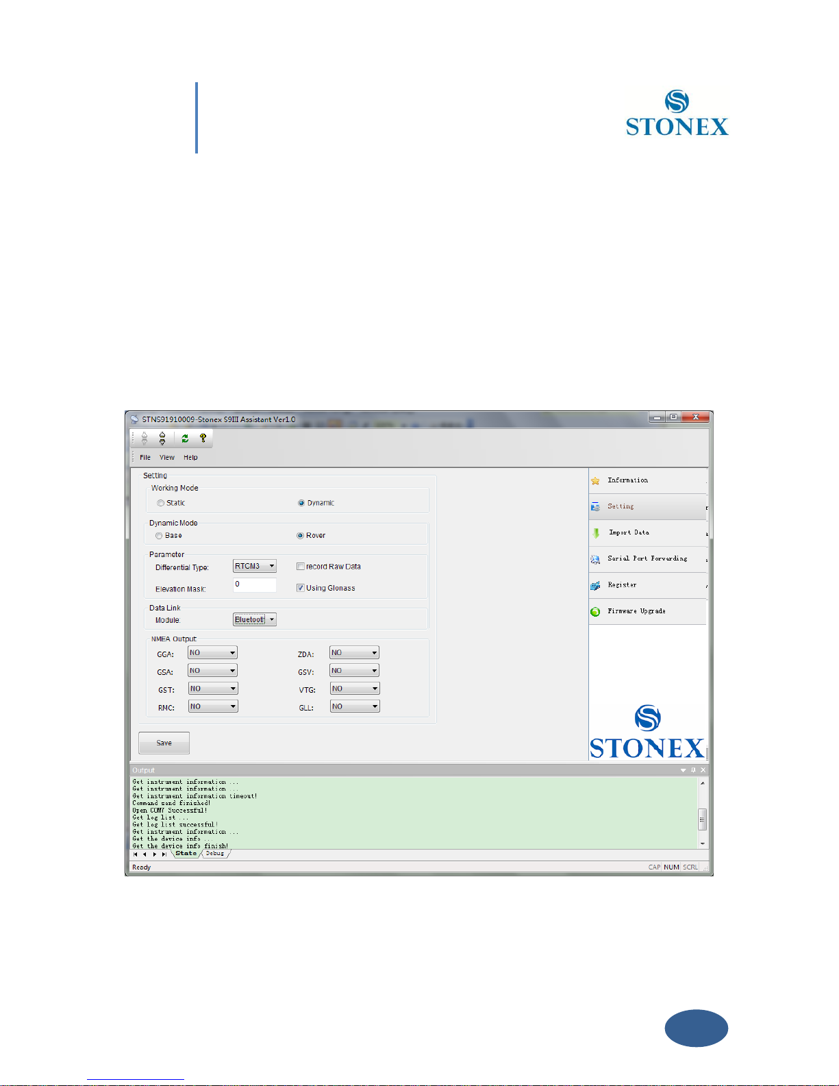
V.2.3.4. Bluetooth
This option give us the possibility to use Bluetooth device for RTK data exchange. In this case
the same channel with commands and position information between handheld and receiver is
used also for transmitting the differential corrections from handheld to the receiver, for
example if the handheld is connected through internet or it is connected to a mobile phone
connected to internet. Please remember that if you select Bluetooth as datalink, you don’t see
any datalink led on the display.
Fig. 5.14 - Bluetooth
Page 49
48
Chapter V: Stonex Assistant for S9III
When you have completed all your selection, please click on “Save” button and the
configuration will be stored inside S9 memory.
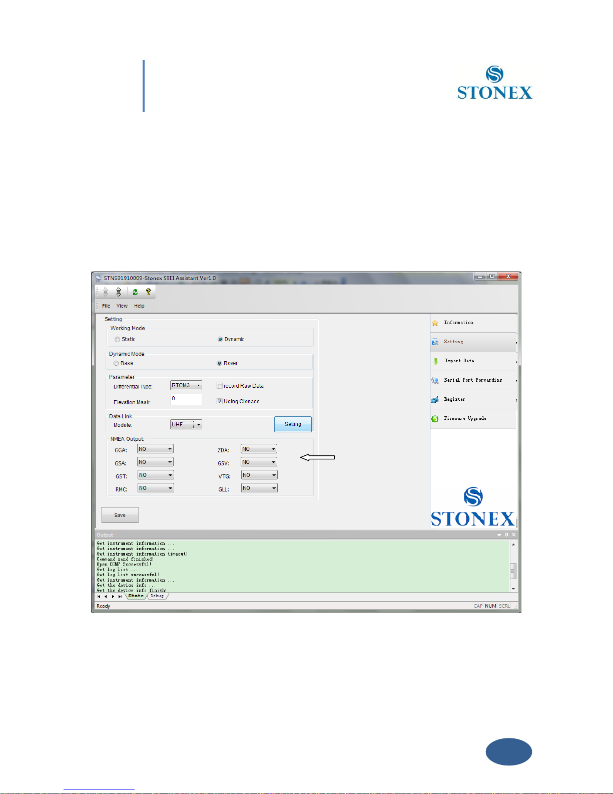
V. 2.4 NMEA Output string
NMEA output messages setting is available in the Setting session, as you can see in the following
figure 5.15.
Fig 5.15 - NMEA String
In this area you can configure the default NMEA messages that are output to the datalogger at
Page 50
49
Chapter V: Stonex Assistant for S9III
the startup of the receiver, enabling or disabling the different string.
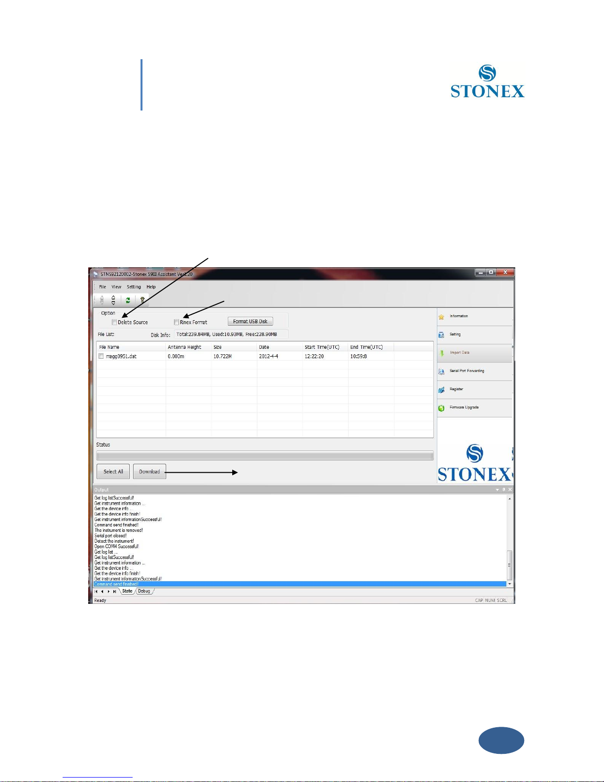
V.3 Import Data
This section of the Assistant allows the user to download raw data from S9III memory to Pc,
instead of doing manual copy of files. After connecting the receiver click on “Import Data”: a
new window is opened as in Fig. 5.16.
Fig. 5.16 – Import Data window
Inside this window you can see all files saved in the memory of S9III (excluding the
1 Rinex
2 Delete
3 Download
Page 51

50
Chapter V: Stonex Assistant for S9III
configuration file), which are files with raw GPS measures. By checking only one box or more
at the left of each file, you can select it for download operations.
You can also choose to convert the downloaded file into RINEX format by checking at box
“Rinex format” in the Option area on the top of the page. Checking at “Delete Source” you can
enable the automatic erase of the selected files after download on the PC memory.
Using the “Download” button, at the bottom of the form, you can save the marked files on your
PC, in the folder you prefer. In this section you can also modify the value of the antenna height
of the receiver used during survey.
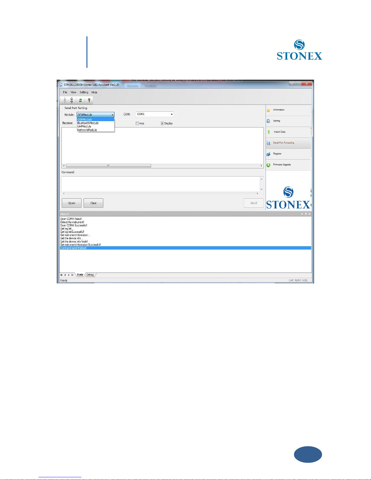
V. 4 Serial Port Forwarding
This function is for advanced users and technical support only.
Port forwarding allows the configuration of the GNSS OEM module, UHF module and GPRS
module directly. This functionality is valid only for DB9 serial port connection from 5-pin Lemo.
Click on “Serial Port Forwarding”: a new window is opened as in Fig. 5.17.
Page 52
51
Chapter V: Stonex Assistant for S9III
Fig. 5.17 – Serial Port Forwarding window
Select the module you want to connect and the serial port then press “Open”, then follow the
instruction to restart the receiver. Then you will be able to communicate with the module
directly. Please note that unintended commands might affect the operation of the receiver.
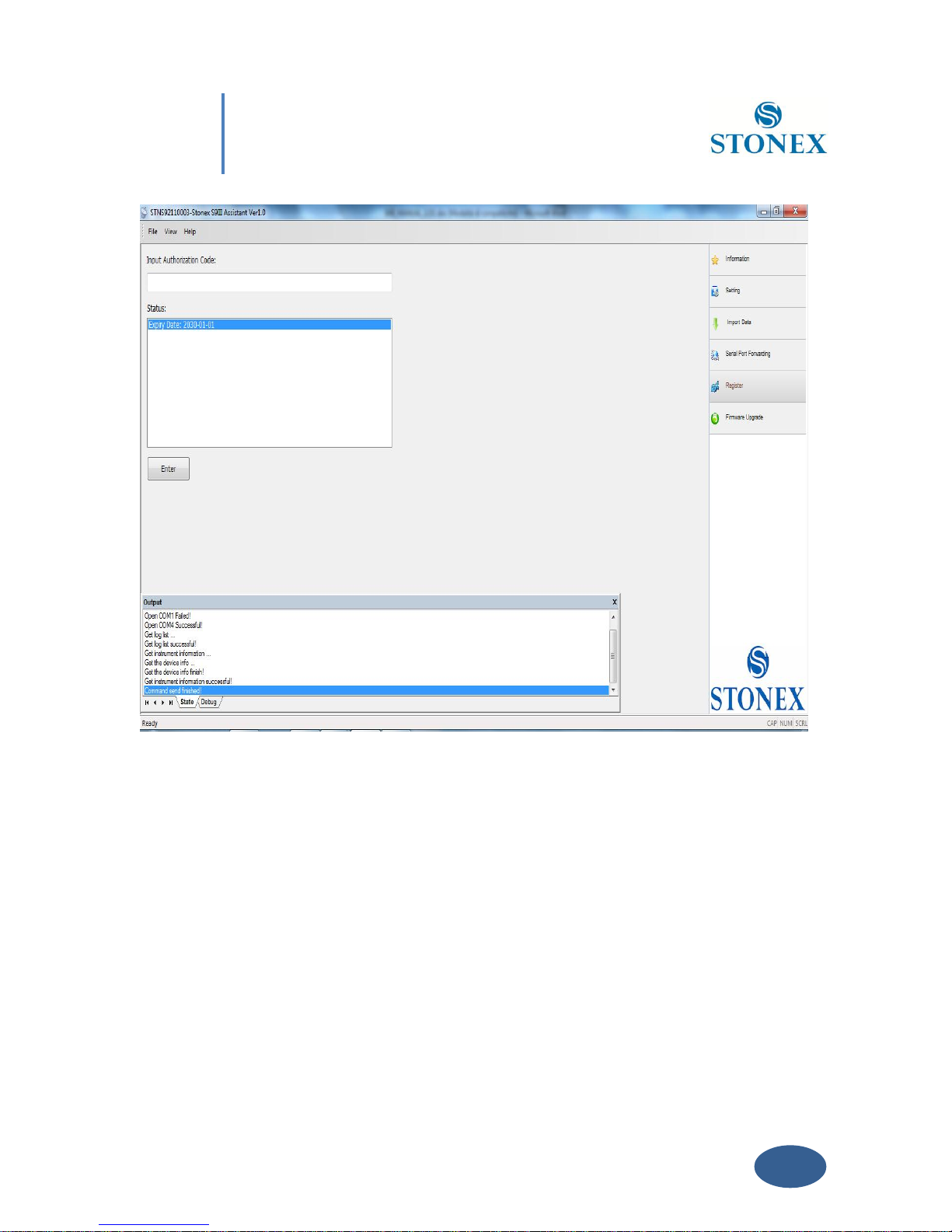
V. 5 Register
This command allows you to register the license code in a different way with respect to that
explained in chapter IV.7. Click on “Register” and a window as in Fig. 5.18 is opened.
Page 53
52
Chapter V: Stonex Assistant for S9III
Fig. 5.18 –Register the receiver
1) In the “Status” window, you can see the data of expiry of the license, if the expire date
contains the year 2030, it means that the license is already permanent.
2) In the “input authorization code” window you can insert the new temporary or
permanent code provided by Stonex. Click on “Enter” to confirm.
If your code is expired, please ask to your local dealer/agent.
Page 54
53
Chapter V: Stonex Assistant for S9III
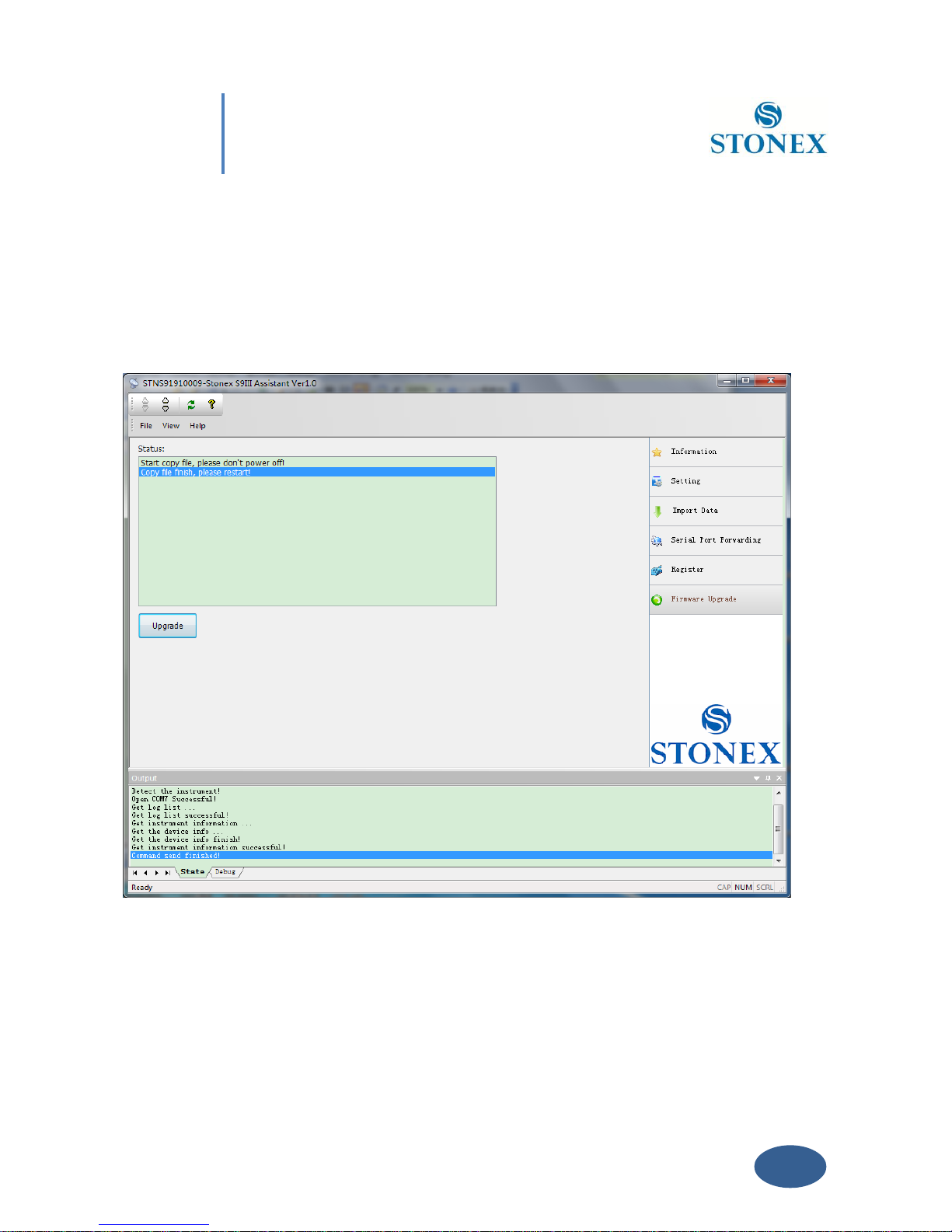
V.6 Firmware update
Click on “Firmware Upgrade” button to select the location of the folder where the update
firmware is located. Then select the firmware file and automatically it will be downloaded into
the receiver, finally restart the receiver. You can see the fig. 5.19 as example.
Fig. 5.19 – Firmware update window
If Stonex will release a new firmware, you will receive a communication from your local
dealer/agent.
Page 55
54
Appendix 1: Default Radio Settings
Appendix 1: Default Radio Settings
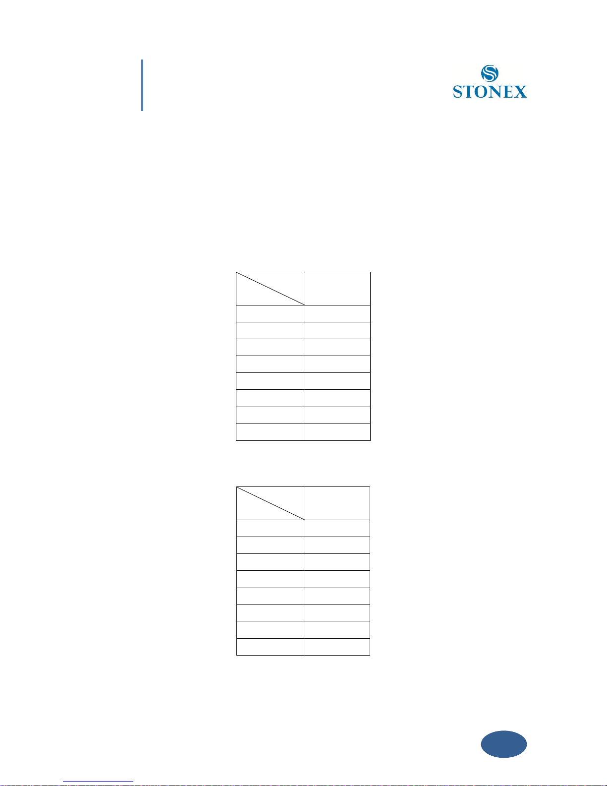
S9III uses a single UHF radio to cover the different the whole band 410-470 MHZ . Preset
values is done directly from Stonex Europe in accord to the following tables :
Rate
Channels
MHz
1 channel
411.050
2 channel
412.050
3 channel
413.050
4 channel
414.050
5 channel
415.050
6 channel
416.050
7 channel
417.050
8 channel
418.050
Tab. 6.1 – Internal radio default frequency (MDA)
Rate
Channels
MHz
1 channel
438.125
2 channel
440.125
3 channel
441.125
4 channel
442.125
5 channel
443.125
6 channel
444.125
7 channel
446.125
8 channel
447.125
Page 56
55
Appendix 1: Default Radio Settings
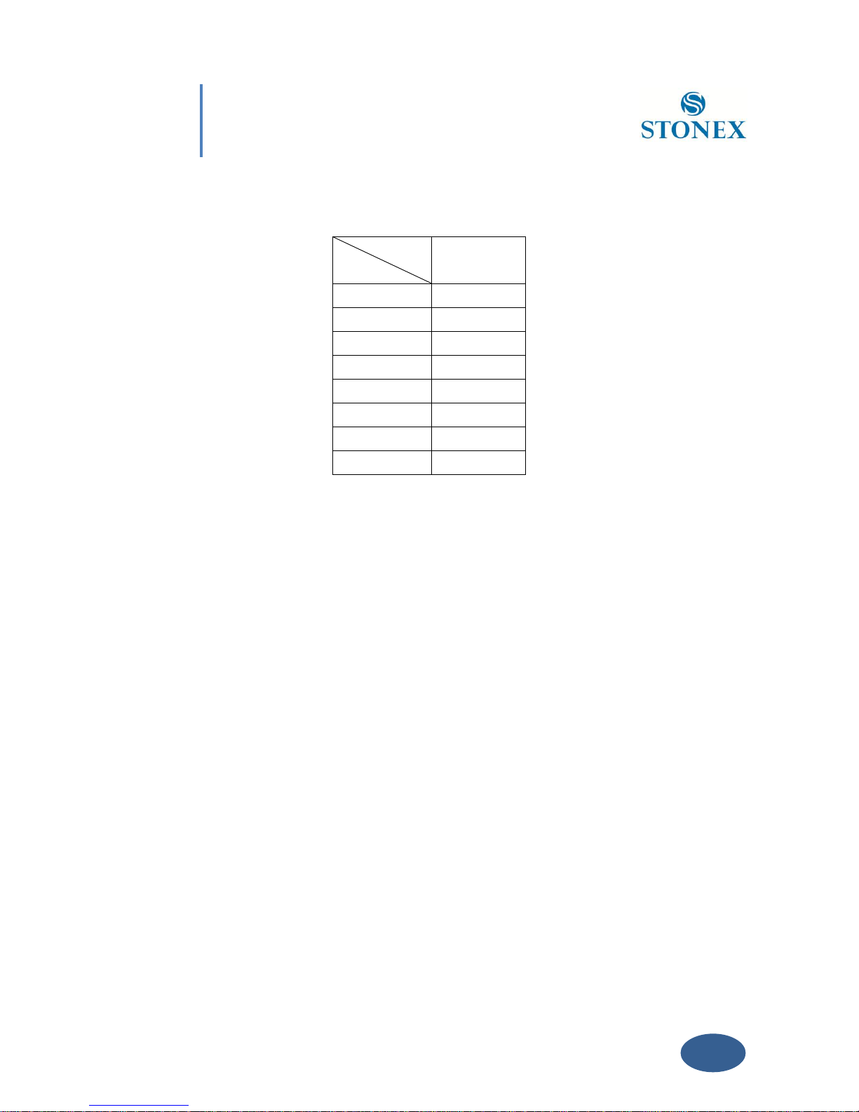
Tab. 6.2 – Internal radio default frequency (MDB)
Rate
Channels
MHz
1 channel
464.500
2 channel
464.600
3 channel
464.450
4 channel
464.650
5 channel
464.400
6 channel
464.700
7 channel
465.350
8 channel
466.750
Tab. 6.3 – Internal radio default frequency (MDC)
Page 57

56
Appendix 2: Self-check procedure
Appendix 2: Self-check procedure
Self-Check: it is a procedure predisposed for verifying the correct working of the instrument
devices, the operation way is:
- Press and hold I key for more than 10 seconds, as for turning it off, but keeping pressed
the key after all lights have turned off.
- Release the key when you hear another beep: receiver will start to make a self-check.
Self-check lasts typically around 30 seconds. During this procedure the meaning of lights is:
- Internal radio led: ON if UHF module pass the test; FLASH if UFH module fails the test.
- GSM/GPRS led: ON if GSM/GPRS module pass the test; FLASH if GSM/GPRS module fails
the test.
- satellite led: ON if GNSS OEM module pass the test; FLASH if GNSS OEM module fails the
test
If you have noticed at least one problem during self-check, please contact your local dealer or
email to [email protected]
After the self-check procedure the receiver will turn on and begin to work normally.
Page 58

57
Appendix 3: Technical Specifications
Appendix 3: Technical Specifications
GNNS module specifications:
Channels: 220
Satellite signals tracked:
GPS: Simultaneous L1 C/A, L2E, L2C, L5.
GLONASS: Simultaneous L1 C/A, L1 P, L2 C/A (GLONASS M Only), L2 P.
SBAS: Simultaneous L1 C/A, L5.
GIOVE-A: Simultaneous L1 BOC, E5A, E5B, E5AltBOC1.
GIOVE-B: Simultaneous L1 CBOC, E5A, E5B, E5AltBOC1.
COMPASS: (reserved): B1 (QPSK), B1-MBOC (6, 1, 1/11), B1-2 (QPSK), B2 (QPSK),
B2-BOC (10, 5), B3 (QPSK), B3BOC (15, 2.5), L5 (QPSK).
Very low noise GNSS carrier phase measurements with <1 mm precision in a 1 Hz
bandwidth.
High precision multiple correlator for GNSS pseudo range measurements.
Unfiltered, unsmoothed pseudo range measurements data for low noise, low multipath
error, low time domain correlation and high dynamic response.
Proven low elevation tracking technology.
20 Hz raw measurement & position outputs.
Signal recapture < 1 sec (**).
RTK signal initialization typically < 10 sec (**).
Initial capture time typically < 15 sec (**).
Internal Memory: 4 Gb with micro SD card (over than 60 days of raw static data
storage with recording sample every 1 second)
Page 59

58
Appendix 3: Technical Specifications
Receiver accuracy
Static horizontal accuracy= 3mm ± 1ppm (RMS) (*).
Static vertical accuracy= 5mm ± 1ppm (RMS) (*).
Fixed RTK horizontal accuracy= 1cm ± 1ppm (RMS) (*).
Fixed RTK vertical accuracy= 2cm ± 1ppm (RMS) (*).
Code differential positioning accuracy= 0.45m (CEP) (*).
Stand Alone RTK positioning accuracy= 1.5m (CEP) (*).
SBAS positioning accuracy typically< 5m (3D RMS) (*).
Connection devices and protocols :
Connectors I/O: 7-pins LEMO and 5-pins LEMO interfaces.
Multi-cable with USB interface for connecting with PC.
2.4GHz Bluetooth device class II: maximum range is 50m.
GSM/GPRS data modem
Cable for RTK connection by external datalink(optional).
Serial protocols
Reference outputs: CMR, CMR+, RTCM 2.3, RTCM 3.0, RTCM 3.1.
Navigation outputs: GGA ZDA GST GSV GSA GGK GLL RMC VTG
Page 60

59
Appendix 3: Technical Specifications
.
Radio module
Internal transmitting and receiving radio: MDS TRM 450
Frequency range available: 410-470 MHz.
Emitting power: 0.5 W – 1 W
Compatibility with Trimtalk protocol (Trimble/Pacific Crest radio).
GPRS/GSM module
The GPRS/GSM board mount a Telit_GC864-QUAD_V2 unit for GSM/GPRS communication.
This module supports:
- Quad-band operation at 800 MHz, 900 MHz, 1800 MHz, 1900 MHz.
- GPRS Multislot class 12.
- EDGE (E-GPRS) Multishot class 10.
- GSM release 99.
- Output power: class 4 (2 W) for EGSM850 AND EGSM900, class 1 (1 W) for GSM1800
and GSM1900.
Power Supply:
9 to a 15V DC external power input with over-voltage.
Voltage: 7.2 V.
Page 61

60
Appendix 3: Technical Specifications
Working time in static mode: typically 6 hours.
Working time in RTK rover mode: typically 4 hours.
Charge Time: typically < 7 hours.
Power consumption: < 3.8 W.
Remaining time with battery light blinking: 1 hour.
Physical specification:
Size: Height 96 mm x Diameter 186mm. 60 mm from the center of the rubber loop to
the bottom.
Weight: 1.2 Kg with internal battery, radio standard UHF antenna.
Operational temperature: -30°C to 60°C (-13°F to 140°F) (Internal radio TX mode 50°C)
Storage temperature: - 40°C to 80°C (-67°F to 185°F)
Waterproof: protected from temporary immersion to depth of 1 meter and from 100%
humidity.
Dustproof.
Shock resistance: designed to survive a 2m pole drop on the concrete.
Vibration resistance.
*This specifications depends on weather and satellite visibility conditions
** This specification depends on satellite visibility conditions
Page 62

61
Appendix 4: Copyrights, warranty and
environmental recycling
Appendix 4: Copyrights, warranty and environmental
recycling
Copyrights and trademarks
© 2012, STONEX® Limited. All rights reserved.
STONEX®, the STONEX® logo, and S9III GNSS receiver are trademarks of STONEX® Limited
STONEX® Assistant, STONEX® GPS Processor and STONEX® SurvCE are trademarks of STONEX®
Limited.
Bluetooth is a trademark owned by Bluetooth SIG, Inc. and licensed to Trimble Navigation
Limited. All other trademarks are the property of their respective owners.
Release Notice
This is the June 2012 release of the STONEX® S9III GNSS new model receiver user guide.
The following limited warranties give you specific legal rights. You may have others, which vary
from state/jurisdiction to state/jurisdiction.
Standard Limited Warranty
Version 2012
The terms and conditions of this Limited Warranty constitute the complete and exclusive
warranty agreement between The Customer or Dealer and STONEX® for the Product and
supersedes any prior agreement or representation made in any STONEX® sales document or
advice that may be provided to Customer by any STONEX® representative in connection with
Customer’s purchase of the Product. No change to the conditions of this Limited Warranty is
valid unless it is made in written form and signed by an authorized STONEX® supervisor.
STONEX ® Europe warrants that its Products:
Page 63

62
Appendix 4: Copyrights, warranty and
environmental recycling
(1) are free from defects in materials or workmanship for generally 2 years (see
appendix 4 ).
a) accessories or specific parts for which different limited warranty period shall
apply(see appendix 5).
(2) have been tested/calibrated in proper working status prior to shipment.
The warranty period starts from date of first sale of the instruments. At its sole discretion,
under the warranty period, STONEX® Europe will repair the product or send parts for
replacement at its expense. STONEX® Europe agrees to repair or replace the defected
instrument within thirty (30 ) days only if STONEX® Europe recognizes that the defects of the
instrument are not caused by human factors or no obvious damage to its surface is visible.
STONEX® Europe warrants any new replaced parts or products are warranted to be free from
defects in materials and workmanship for thirty (30) days or for the remainder of the Limited
Warranty Period of the Product in which they are installed, whichever is longer. Faulty Parts
or Products replaced under this Limited Warranty shall become property of STONEX®Europe.
All products that have to be repaired have to be returned to our technical representative
office location via any delivery company the customer prefers, nevertheless STONEX® Europe
is not accountable for the unlikely event that the Products gets lost in transit.
Any damage inflicted by the customer or by third party after the products has been delivered to
the customer is excluded from the limited warranty as well any damage arising from an
improper use, from any action or use not provided for in the enclosed user guides and/or
manuals.
Shipping policy.
The Customer or the dealer is required to pay for the charges for shipping of fault
parts or instruments to STONEX® Europe representative office and STONEX®
Europe is providing the shipping for return. Dealers needs to follow STONEX® Europe
repair/service procedure (see appendix 6) to achieve a better and prompt service result.
Page 64

63
Appendix 4: Copyrights, warranty and
environmental recycling
Return policy Dead On Arrival instruments.
All returned products have to be shipped to STONEX® Europe representative office.
The original Purchaser has a period of seven (7) days starting from date of purchasing to signal
the existence of a defect in the instrument for a full refund (less shipping and handling),
provided the merchandise is in new, resalable condition and returned in the original,
undamaged packaging. Customer has to pay for both the return and the original freight fees,
regardless of the original freight paid by the Company. All warranty books, instruction manuals,
parts and accessories must be included as well as the original box in which the item was
shipped. We recommend to place the original carton inside another box, to avoid any additional
damage to the carton itself. In some cases, returns of special items will require a re-stock fee.
Acceptance of returned merchandise is final only after inspection by STONEX®Europe.
Above terms and policies shall apply as for hardware. Dealers needs to follow STONEX®Europe
repair/service procedure (see appendix 4) to achieve a better and prompt service result.
Firmware/Software warranty.
Stonex Europe doesn’t warrant that operation of Firmware/Software on any instruments will
be uninterrupted or error-free, or that functions contained in Firmware/Software will operate
to meet your requirements.
Stonex will forward the Software/Firmware Fix to the dealer or customer. Firmware/software
Fix means an error correction or other update created to fix a previous firmware version that
substantially doesn’t conform to the instruments specification.
Over Warranty repair(s) policy.
Customer shall pay the standard repair fees for any service (whether part replacement or
repairs) and performed by STONEX®Europe under request and explicit authorization of the
customer itself. In this case the customer is charged for return shipment’s fees as well.
Page 65

64
Appendix 4: Copyrights, warranty and
environmental recycling
Disclaimer and Limitation of Remedy.
ALL OTHER EXPRESS AND IMPLIED WARRANTIES FOR THIS PRODUCT, INCLUDING THE
IMPLIED WARRANTIES OF MERCHANTABILITY AND FITNESS FOR A PARTICULAR PURPOSE
AND/OR NONINFRINGEMENT OF ANY THIRD PARTY’S RIGHTS, ARE HEREBY DISCLAIMED.
STONEX® EXPRESSLY DISCLAIMS ALL WARRANTIES NOT STATED IN THIS LIMITED
WARRANTY. ANY IMPLIED WARRANTIES THAT MAY BE IMPOSED BY LAW ARE LIMITED IN
DURATION TO THE TERM OF THIS LIMITED WARRANTY. SOME JURISDICTIONS DO NOT
ALLOW THE EXCLUSION OF IMPLIED WARRANTIES OR LIMITATIONS ON HOW LONG AN
IMPLIED WARRANTY LASTS, SO THE ABOVE EXCLUSIONS OR LIMITATIONS MAY NOT APPLY
TO CUSTOMER. CUSTOMER MUST READ AND FOLLOW ALL SET-UP AND USAGE
INSTRUCTIONS IN THE APPLICABLE USER GUIDES AND/OR MANUALS ENCLOSED. IF
CUSTOMER FAILS TO DO SO, THIS PRODUCT MAY NOT FUNCTION PROPERLY AND MAY BE
DAMAGED. CUSTOMER MAY LOSE DATA OR SUSTAIN PERSONAL INJURIES. STONEX®, ITS
AFFILIATES AND SUPPLIERS DO NOT WARRANT THAT OPERATION OF THIS PRODUCT WILL
BE UNINTERRUPTED OR ERROR FREE; AS DO ALL ELECTRONICS AT TIMES. IF THIS
PRODUCT FAILS TO WORK AS WARRANTED ABOVE, CUSTOMER’S SOLE AND EXCLUSIVE
REMEDY SHALL BE REPAIR OR REPLACEMENT. IN NO EVENT WILL STONEX®, ITS
AFFILIATES OR SUPPLIERS BE LIABLE TO CUSTOMER OR ANY THIRD PARTY FOR ANY
DAMAGE IN EXCESS OF THE PURCHASE PRICE OF THE PRODUCT. THIS LIMITATION APPLIES
TO DAMAGES OF ANY KIND WHATSOEVER INCLUDING (1) DAMAGE TO, OR LOSS OR
CORRUPTION OF, CUSTOMER’S RECORDS, PROGRAMS, DATA OR REMOVABLE STORAGE
MEDIA, OR (2) ANY DIRECT OR INDIRECT DAMAGES, LOST PROFITS, LOST SAVINGS OR
OTHER SPECIAL, INCIDENTAL, EXEMPLARY OR CONSEQUENTIAL DAMAGES, WHETHER FOR
BREACH OF WARRANTY, CONTRACT, TORT OR OTHERWISE, OR WHETHER ARISING OUT OF
THE USE OF OR INABILITY TO USE THE PRODUCT AND/OR THE ENCLOSED USER GUIDES
AND/OR MANUALS, EVEN IF STONEX®, OR AN AUTHORIZED STONEX® REPRESENTATIVE,
AUTHORIZED SERVICE PROVIDER OR RESELLER HAS BEEN ADVISED OF THE POSSIBILITY
OF SUCH DAMAGES OR OF ANY CLAIM BY ANY OTHER PARTY. SOME JURISDICTIONS DO NOT
Page 66

65
Appendix 4: Copyrights, warranty and
environmental recycling
ALLOW THE EXCLUSION OR LIMITATION OF INCIDENTAL OR CONSEQUENTIAL DAMAGES
FOR SOME PRODUCTS, SO THE EXCLUSIONS OR LIMITATIONS MAY NOT APPLY TO
CUSTOMER. THIS LIMITED WARRANTY GIVES CUSTOMER SPECIFIC LEGAL RIGHTS, AND
CUSTOMER MAY ALSO HAVE OTHER RIGHTS WHICH VARY FROM
COUNTRY/STATE/JURISDICTION TO COUNTRY/STATE/
Instruments
Two (2) years on STONEX® Products:
GPS receiver: S9 GNSS Series/Vector/ Walker II / PLT1
Accessories.
Accessories & Specific Parts Warranty :
For Accessories provided by Stonex with the instruments S9 GNSS the following general
warranty time is for reference:
Batteries: 7 months.
Battery chargers: 7 months.
Adapters for battery chargers, Cables, Tribrach, Pole, Antennas: 2 years.
Restriction for GPS Boards.
For GPS receiving boards (Trimble, Novatel) used on S9 and S8 family of GPS receivers, Stonex
Europe provides warranty time for one (1) year.
Service Procedure
Repair/Service procedure for dealers.
(1) S/N of the instrument and a detailed description of the defect (sometimes pictures or video)
will be required to indicate the cause and problem.
(2) If dealer wants to repair an instrument under warranty period on their site:
1) If dealers don’t have the part in stock they have to send an official order to STONEX®
Page 67

66
Appendix 4: Copyrights, warranty and
environmental recycling
Europe and pay for it and so STONEX® Europe will send the new part to them so they can
repair the instrument.
2) When the repair is over, the dealer has to fill the “Spare Part Refund” module and send it
to the dedicated mail address.
3) wait for STONEX® Europe’s authorization SPR no;
4) when dealer receive the SPR authorization no they can send back to STONEX® Europe
appointed office the broken part with attached the SPR module;
5) when STONEX® Europe receives the broken part STONEX® Europe shall verify it and
if everything is ok the cost of the part shall be refund ( refund will be done only after
check of the failure part and final approval of STONEX® Europe).
(3) If the instrument needs to be sent back to STONEX® Europe for repair/replacement,
dealer/customer has to send to STONEX® Europe a “Returned Merchandise Authorization
(RMA)” before they send back the fault instrument. STONEX® Europe shall, at its sole
discretion, decide on the place of performance for work under warranty.
Environmental recycling
The cardboard box, the plastic in the package and the various parts of this product have to be recycled
and disposed of in accordance with the current legislation of your Country.
FOR COUNTRIES IN THE EUROPEAN UNION (EU)
The disposal of electric and electronic device as solid urban waste is strictly prohibited: they
must be collected separately.
Contact Local Authorities to obtain practical information about correct handling of the waste,
location and times of waste collection centres. When you buy a new device of ours, you can give
back to our dealer a used similar device.
The dumping of these devices at unequipped or unauthorized places may have hazardous
effects on health and environment.
Page 68
67
Appendix 4: Copyrights, warranty and
environmental recycling
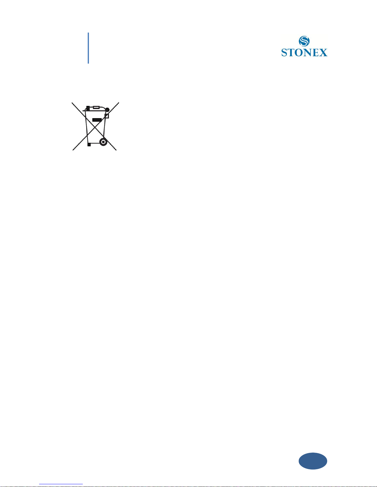
The crossed dustbin symbol means that the device must be taken to authorized collection centers and
must be handled separately from solid urban waste.
FOR COUNTRIES OUTSIDE EUROPEAN UNION (EU)
The treatment, recycling, collection and disposal of electric and electronic devices may vary in
accordance with the laws in force in the Country in question.
Page 69

 Loading...