

Page 1
(September 2017)-Ver.1-Rev.0 – Firmware Version: 0.22.170401
www.stonex.it
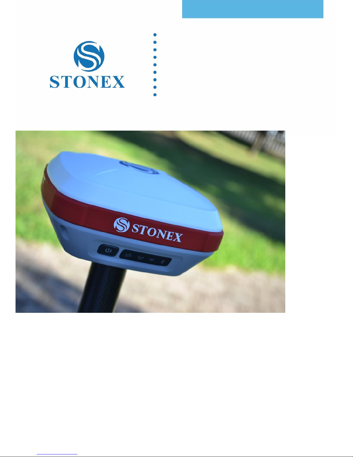
STONEX S800A
GNSS Receiver
User Manual
Page 2

S800A GNSS Receiver – User Manual 1
Contents
1. Brief Introduction ........................................................................................ 3
1.1 Introduction ................................................................................................................... 3
1.2 Features ........................................................................................................................... 4
1.3 Precaution ....................................................................................................................... 4
2. S800A Surveying System ............................................................................ 5
2.1 S800A Receiver ............................................................................................................. 5
2.1.1 Receiver appearance ............................................................................................... 5
2.1.2 The bottom of Receiver ......................................................................................... 5
2.1.3 Control Panel ............................................................................................................. 6
2.1.4 Mode View and Mode Switch ............................................................................. 9
2.1.5 Receiver Self-check .................................................................................................. 9
2.2 Standard Accessories .............................................................................................. 10
2.2.1 Transport container .............................................................................................. 10
2.2.2 Adaptor ..................................................................................................................... 10
2.2.3 UHF Antenna ........................................................................................................... 11
2.2.4 7-pin Serial Cable .................................................................................................. 12
2.2.5 Other Accessories.................................................................................................. 13
3. Field Surveying ........................................................................................... 14
3.1 Static Surveying ......................................................................................................... 14
3.1.1 Static Surveying Introduction ........................................................................... 14
3.1.2 Static Surveying Operation ............................................................................... 15
3.1.3 Design Principles of GPS Control Network ................................................ 16
3.1.4 Data acquisition method .................................................................................... 16
3.2 RTK Dynamic Measurement (Radio) ................................................................. 17
3.2.1 Installation of Base ............................................................................................... 17
3.2.2 Start of Base ............................................................................................................ 18
3.2.3 Installation of Rover ............................................................................................. 18
3.2.4 Configuration of Rover ....................................................................................... 19
3.3 RTK Dynamic Measurement (Network) ........................................................... 20
3.3.1 Installations of Base and Rover ....................................................................... 20
3.3.2 Configuration of Rover ....................................................................................... 20
4. Web UI Application ................................................................................... 21
4.1 Status ............................................................................................................................. 22
4.2 Settings ......................................................................................................................... 23
4.3 Download ..................................................................................................................... 24
4.4 Management .............................................................................................................. 24
4.4.1 Device Register....................................................................................................... 25
Page 3

S800A GNSS Receiver – User Manual 2
Appendix 1: S800A Receiver Specification ............................................................ 26
Appendix 2: Default Radio Configuration .............................................................. 28
Appendix 3: Copyrights, warranty and environmental recycling ................. 29
Appendix 4: Safety Recommendations ................................................................... 37
Page 4

S800A GNSS Receiver – User Manual 3
1. Brief Introduction
1.1 Introduction
Thank you for choosing our products. STONEX®, as a leading RTK
manufacturer, is committed to providing the most advanced GNSS surveying
tools.
This manual applies to S800A products, containing instructions for installing,
configuring the product and operating it. Even if you have used other RTK
products of ours before, we recommend that you spend some time reading
this manual for better user experience.
S800A is a superminiature GNSS RTK receiver of STONEX®. With brand-new
appearance design and solid magnesium alloy structure, it supports GPS,
GLONASS, BeiDou 2nd generation and Galileo satellite navigation system,
which meets accuracy demands of modern surveying to provide reliable
surveying results and user friendly operation. S800A brings you the utmost
experience.
One new features inside S800A is Atlas reception : Atlas is a differential
corrections systems broadcasted on L-Band, allowing increase in position
accuracy in area not covered by conventional Cors working under Ntrip
Technology ( lack of reference stations, lack of GPRS signals, etc ). Atlas is
broadcasted by satellite systems ,so the reception is nearly ensured all over
the world . Atlas uses similar technology compared to SBAS, but providing
better positioning accuracy.
Page 5

S800A GNSS Receiver – User Manual 4
1.2 Features
Multi-constellation system. Supports BeiDou, GPS, GLONASS and Galileo
multi-system navigation and positioning.
Compact and convenient. High integration.
IP67 Waterproof and Dust Proof Rating. Shock resistant.
Highly integrated internal antenna. Zero phase center offset.
Onboard 8G memory.
Powerful battery endurance with over 10 hours’ continuous
operation.
1.3 Precaution
Transportation:during the transport, the receiver and its accessories must
be reasonably placed in its transport container, to protect against shock and
vibration. Specially note that S800A contains a non-removable internal
Lithium Battery, whose national and international regulations must be
observed and fulfilled in transportation.
Storage: before storage, discharge battery below 30%. After storage
recharge batteries before using. A proper storage temperature in a dry
environment is recommended to minimize self-discharging of the battery.
Keep the receiver dry in storage and before using.
Cleaning and Drying: use only a clean, soft, lint-free cloth for cleaning. If
necessary, moisten the cloth with water or pure alcohol. In all kinds of
weather conditions, after coming back from the field, dry the product, the
transport container, the foam inserts and the accessories. Pack them after
they have dried. Keep plugs clean and dry. Wet connectors must be dry
before attaching the dust cap.
Page 6
S800A GNSS Receiver – User Manual 5
2. S800A Surveying System
S800A surveying system consists of three main components, namely receiver,
handheld and accessories. In the following parts are their introductions.
2.1 S800A Receiver
2.1.1 Receiver appearance
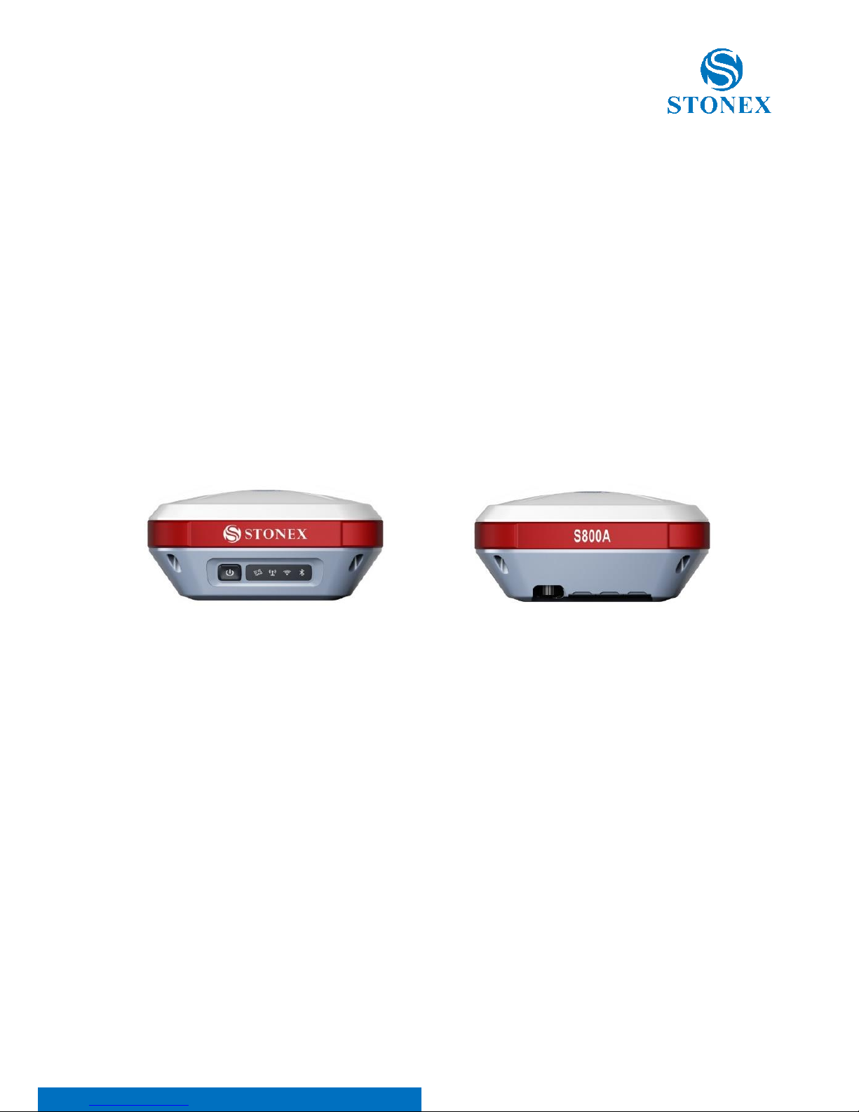
The receiver’s dimension is 146mm*146mm*76mm, weighting 1.2kg, with its
appearance as illustrated in Figure 2-1. The front side is control panel,
consisting of 1 power button and 4 indicators. The bottom are interfaces of
UHF antenna and cables.
Figure 2-1 S800A Receiver
2.1.2 The bottom of Receiver
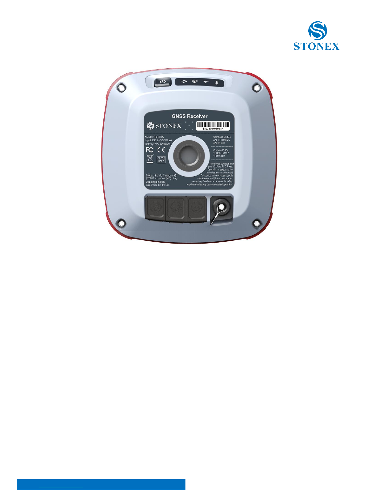
At the bottom of the receiver is labelled system-unit serial number. The
bottom interfaces are illustrated in Figure2-2, with covers for dust and water
prevention.
Page 7
S800A GNSS Receiver – User Manual 6
Figure 2-2 Receiver bottom
TNC interface: connect internal radio antenna.
2-pin LEMO port: charge for internal battery, connect adaptor.
5-pin LEMO port: connect external power supply and external radio
7-pin LEMO port: connect PC or handheld, USB+serial port
2.1.3 Control Panel
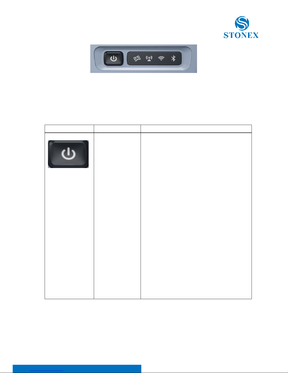
Control Panel is illustrated in Figure 2-3.
Page 8
S800A GNSS Receiver – User Manual 7
Figure 2-3 Control Panel
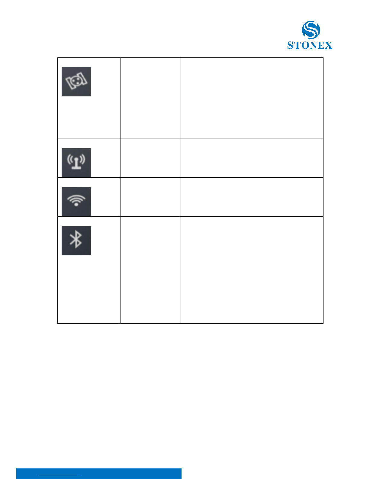
Function descriptions of power button and indicators are shown in Table 2-1.
Table 2-1 Indicator function description
Indicator
Status
Description
Power button
On: sufficient
power
Fast flashing
(1s): low power
(below 10%)
Slowly flashing
(3s): charging
When the S800A receiver is powered on,
the power indicator will be lit. According
to battery power, the power indicator
shows the following three different
statuses:
1. On (Green): sufficient power supply
2. Fast flashing: power below 10%,
indicator flashing once per second
3. Slowly flashing: charging, indicator
flashing once per 3 seconds
Note: Most often, when power indicator
is fast flashing, the internal battery can
support receiver to continuously work for
only 1 hour. The indicator shows both
statuses of internal battery and external
power, and when the receiver connects to
external power, the indicator will
automatically switch to showing status of
external power.
Page 9
S800A GNSS Receiver – User Manual 8
Satellite led
Blink: Lock
satellites
Off: invalid
solution (Lock
no satellite)
This led shows the amount of locked
satellites. When the receiver locks more
than one satellite, the led will start
flashing in a loop per 30 seconds,and
the number of flashes is the number of
the satellites locked by the receiver.
When the receiver locks no satellite, it’s
off.
Data link led
Flashing: data is
transmitting
When the receiver starts to transmit or
receive data, the led starts flashing.
WIFI led
On: WIFI on
Off: WIFI off
When WIFI is on, the led is lit green.
When the WIFI is off, the led is off.
Bluetooth led
On: Bluetooth
has connected.
Flashing:
Bluetooth has
connected and
is receiving
differential
data.
Off: no
connection
When receiver is connected to handheld
or other instruments by Bluetooth, the
led will be lit blue.
When receiver has connected to other
instruments by Bluetooth and is receiving
differential data, the led will be flashing.
When receiver doesn’t use Bluetooth, the
led won’t be lit.
Page 10

S800A GNSS Receiver – User Manual 9
2.1.4 Mode View and Mode Switch
a) Mode view
When receiver is powered on, flip the power button and then it will voice
broadcast the current working mode and data link.
b) Mode switch
When the receiver is powered on, connect it with handheld or other
instruments so as to set up and switch the working mode of receiver. See
detailed operation procedures in Cube-a User Manual.
2.1.5 Receiver Self-check
Self-check functionality is to check whether every module works normally.
When S800A receiver has indicators off or module doesn’t work normally,
you can use self-check to inspect the receiver. S800A self-check consists of
four parts, namely GPS, radio, WIFI and Bluetooth. The self-check results will
be voice broadcasted in the process. Self-check operation and result
broadcast are as followed:
a) When receiver is powered on, press power button and hold it until
the receiver voice broadcasts “power off”. Press it again until the receiver
sounds a beep and voice broadcasts “self-check”, which means the receiver
starts to operate self-check. (New receiver is recommended to operate self-
check at least once.)
b) In the process of self-check, each module inspection is followed by
its inspection result. If the module inspection passes, it will voice broadcast
“OK” and module led keeps on until the whole self-check finishes. If the
Page 11

S800A GNSS Receiver – User Manual 10
module inspection fails, it will voice broadcast current module inspection fail,
keep module led flashing and buzzer sounding until you restart the receiver.
Self-check lasts for about 1 minute. If there is self-check failure, please
contact local dealer.
c) If every module indicator is lit with no flashing, and voice broadcast
says every module work normally (such as “GPS self-check. OK.”), it means all
the modules work normally. Receiver starts to work after the whole self-
check finishes.
2.2 Standard Accessories
2.2.1 Transport container
There are two kinds of S800A containers: Rover container and Base
container. These two containers have similar appearances but their insert
layouts are different. (S800A containers are still under production.)
2.2.2 Adaptor
S800A receiver adopts internal battery. You can use adaptor to charge the
receiver. S800A receiver and handheld share the same adaptor model as
illustrated in Figure 2-12.
Page 12
S800A GNSS Receiver – User Manual 11
2.2.3 UHF Antenna
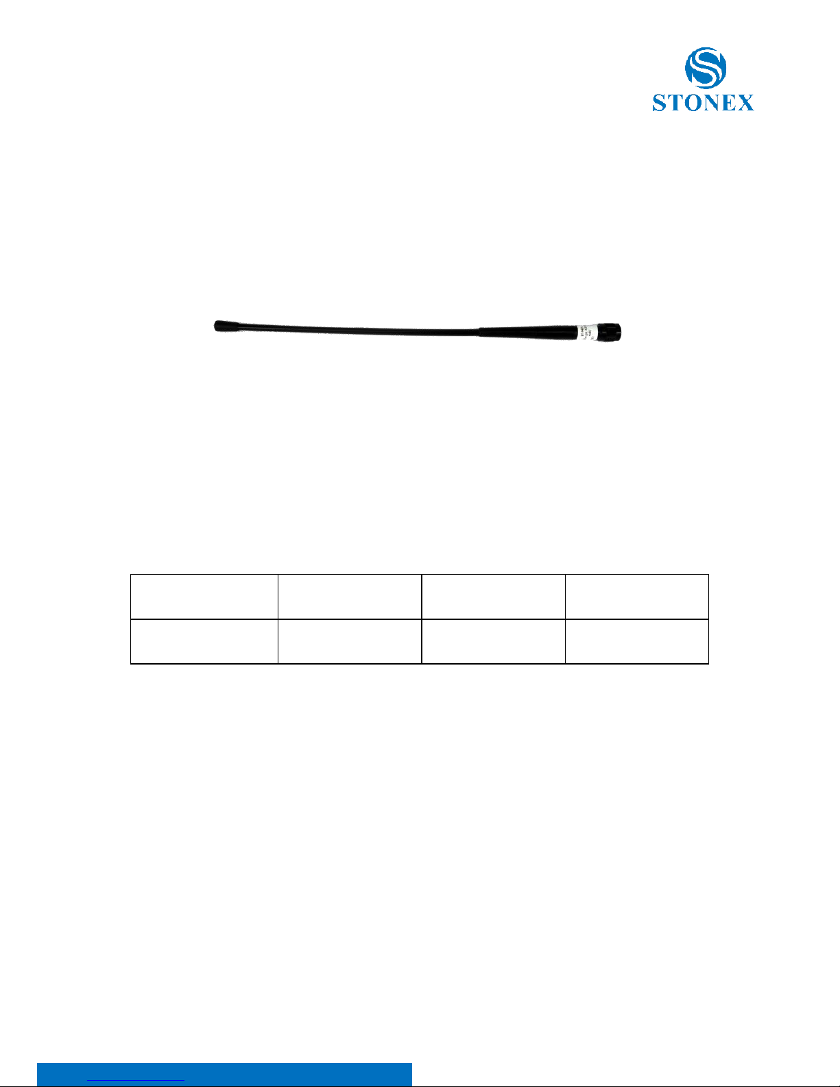
When receiver is in internal radio mode, UHF antenna (as illustrated in Figure
2-15) is in need.
Figure 2-15 UHF antenna
UHF antennas have 3 models, respectively covering 3 frequency ranges as
shown in Table 2-6.
Table 2-6 UHF antenna models
Model
QT410A-1
QT440A-1
QT450A-1
Frequency (MHz)
410~430
430~450
450~470
Page 13
S800A GNSS Receiver – User Manual 12
2.2.4 7-pin Serial Cable
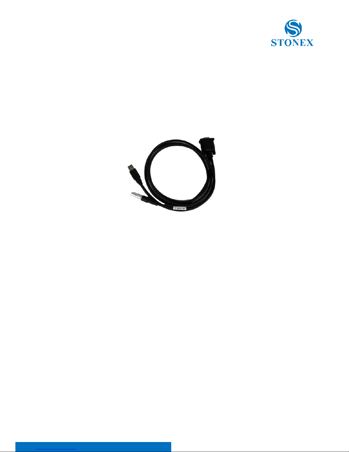
One end of the 7-pin serial cable, the 7-pin serial port, is to connect the
receiver, and the other end of the cable, the USB and the D89 interface are
for data communication respectively with PC and handheld as illustrated in
Figure 2-16.
Figure 2-16 7-pin serial cable
Page 14
S800A GNSS Receiver – User Manual 13
2.2.5 Other Accessories
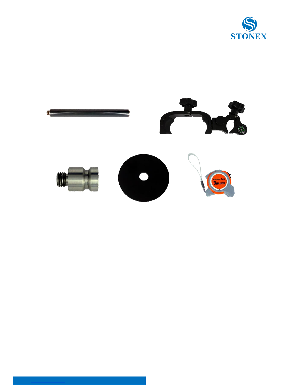
Other accessories include glass mounting pole, controller holder, connector,
tray and measuring tape and other accessories.
Figure 2-17 Glass fiber mounting pole Figure 2-18 Controller holder
Figure 2-19 Connector Figure 2-20 Tray Figure 2-21 Measuring tape
Page 15

S800A GNSS Receiver – User Manual 14
3. Field Surveying
3.1 Static Surveying
3.1.1 Static Surveying Introduction
Static Surveying is an GPS positioning measurement by installing three or
more GNSS receivers at different measuring stations to measure
simultaneously so as to get the relative positions of measuring stations.
Scope of application:
• the establishment of national geodetic control network (second or the
following class)
• the establishment of precise engineering control network, such as
bridges measurement, tunnel measurement
• the establishment of various densified control network, such as city
measurement, mapping control point measurement, road measurement
and boundaries location.
• GPS measurements including control survey used for mapping, cadastral
surveying, land information, real estate surveying, geophysical
prospecting, surveying and building construction in small and medium-
sized cities and towns, which should meet the accuracy demand of D or
E class GPS measurement.
Page 16

S800A GNSS Receiver – User Manual 15
3.1.2 Static Surveying Operation
a. Set up the tripod at the measuring station, switch the receiver to
static mode and attach it to the tribrach, centering and leveling it in strict
standard.
b. Measure the height of antenna.
c. Record names of station and receiver, height of receiver,
measurement start time, measurement end time, observation session and
satellite number.
d. Static data logging: Power on the receiver and make sure it’s in
static mode. Receiver starts to search satellites and satellite led starts to be
flashing. When it meets the record demand, the satellite led will be flashing
at default sampling interval, and one flash represents having logged an
epoch.
e. Power off the receiver after finishing data logging, and then transmit
the data and do the indoor data processing. (See detailed operation
procedures in Cube-a Software (V3.0) User Manual.)
Page 17

S800A GNSS Receiver – User Manual 16
3.1.3 Design Principles of GPS Control Network
(1)In order to ensure the continuous tracking observation of satellites and
quality of satellite signal, set up the GPS measuring station in locations which
are free of obstructions, where the altitude angle of obstacles should be less
than 15° in the field of view.
(2)In order to reduce or avoid interruption from electromagnetic wave to
satellite signal, set up the measuring station away from high-power radio
source (such as television station, broadcasting station and microwave
station). And there should be no object nearby that can strongly reflect
satellite signal (such as large-scale buildings).
(3)Measuring station should have convenient transportation and stable
ground foundation, easy for state holding and beneficial for extension of
other measuring method and joint measurement.
3.1.4 Data acquisition method
There are 2 acquisition methods of data: manual start and automatic start.
Open the Cube-a software on the handheld, click “Device” –
“Communication”, choose the receiver model and the communication mode.
There are Bluetooth and WIFI two communication modes.
a. Manual start
Click “Device” - “Working mode”, choose “Static”. At here, you can configure
static parameters, antenna parameters and satellite system.
b. Automatic start
Click “Device” - “Working mode”, choose “Static”. At parameter settings,
choose auto record static data and at the next time when the receiver is
Page 18

S800A GNSS Receiver – User Manual 17
powered on, it can automatically start static data logging with no need to
reset.
3.2 RTK Dynamic Measurement (Radio)
RTK dynamic measurement (base and rover) has radio mode and network
mode, which two differs from each other in their ways of transmitting
differential signal.
3.2.1 Installation of Base
(1)Set up the tripod in location with known coordinates or unknown
coordinates, level it and attach the receiver on it.
(2)Set up the receiver according to the chosen data link. If using the
internal radio transmission, attach the internal radio antenna into the UHF
antenna port of receiver; if using external radio transmission, connect the
external radio to 5-pin port with 5-pin cable.
(3)Power on the receiver and select base mode.
Page 19

S800A GNSS Receiver – User Manual 18
3.2.2 Start of Base
Open Cube-a on the handheld to choose communication mode. Click
“Device” - “Working mode” to choose base mode and configure its start up
mode, parameters, data link and satellite system and other settings.
Base has 2 start up modes.
a. Use Current Coordinates
Base uses approximate WGS-84 coordinates of current location as base
coordinates.
b. Input Base Coordinates
User specified base coordinates: the specified base coordinates cannot be far
away from the precise WGS-84 coordinates of the current location, otherwise
the base cannot work.
3.2.3 Installation of Rover
After the installation of base, start to install rovers.
(1)Fix the bracket on the pole, fix the handheld to the bracket and then
install the rover on the pole.
(2)Attach the internal radio antenna or connect the external radio
according to the chosen data link.
(3)Power on the receiver and select rover mode.
Page 20

S800A GNSS Receiver – User Manual 19
3.2.4 Configuration of Rover
Open Cube-a software on the handheld to choose communication mode.
Click “Device” - “Working mode” to choose rover mode and configure its
data link, antenna parameters and satellite system and other settings. When
data link is internal radio, you need to configure the radio channel,
frequency, protocol and power.
Note:
1. If you want an high-precision surveying result (several cm), it’s
recommended to use a tripod to install rover;
2. When the coverage of surveying area is large (over 4 km from base),
the working distance too far for internal radio to meet the demand, it’s
recommended to use external radio to connect the receiver;
3. Under radio mode, frequency and protocol settings of base and
rover should be the same.
Page 21

S800A GNSS Receiver – User Manual 20
3.3 RTK Dynamic Measurement (Network)
3.3.1 Installations of Base and Rover
Because RTK network mode is transmitting differential data by network,
differing from radio mode only on their transmission method, the
installations of base and rover are similar. And owing to S800A doesn’t have
internal network functionality, it’s normally not used as a network base.
3.3.2 Configuration of Rover
Open Cube-a on the handheld to choose communication mode. Click
“Device” - “Working mode” to choose rover mode and configure its data link,
antenna parameters and satellite system. When data link is handheld
network, you can configure IP, COM port and AP and other settings. It can
also operate as a RTK by getting access to server through handheld network,
using the handheld network module to get into internet. After connection to
the server, the received differential data can be transmitted to receiver so as
to realize that receiver can be a network RTK without SIM card.
Page 22

S800A GNSS Receiver – User Manual 21
4. Web UI Application
S800A receiver has Web UI functionality. By getting access to its internal
hotspot, you can easily manage it on the Web UI. As long as you have a
smart phone, PC or handheld with WIFI functionality, you can easily connect
to the S800A receiver to view status, download data and configure the
receiver.
S800A receiver is default to open WI-FI automatically when it’s powered on.
Use smart phone/PC/handheld to search the receiver hotspot, whose name is
its serial number, and connect it. (Receiver WI-FI only supports getting
access to Web UI to check status and set up mode, not for Internet
connection.)
After connecting to the S800A receiver WI-FI, open the browser and enter
“192.168.10.1” in IP address. A window pops up and asks for user and
passport. The default user and password are shown as following:
User: admin Password: passport
And then you can login the Web UI of S800A receiver.
Page 23
S800A GNSS Receiver – User Manual 22
4.1 Status
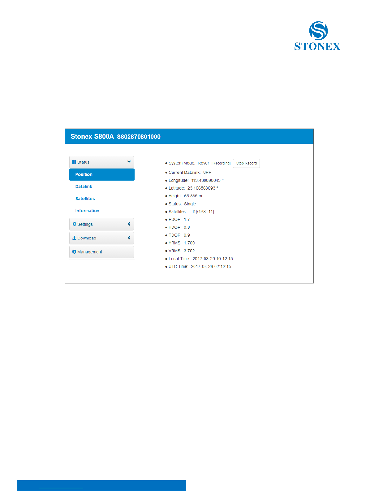
In Status, you can check the current status of receiver, including position,
data link, satellite and device information. You can see detailed information
with respective tap as illustrated in Figure 4-1.
Figure 4-1 Position information
Page 24
S800A GNSS Receiver – User Manual 23
4.2 Settings
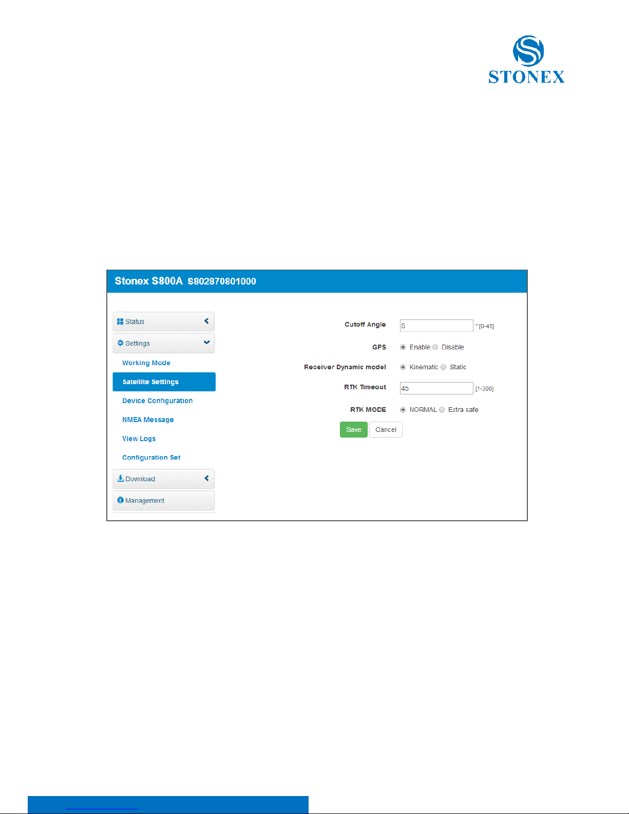
In Settings, there are 6 options, namely working mode, satellite settings,
device configuration, NMEA message, view logs and configuration set. At
here, you can configure the receiver working mode, satellite system, system
parameter and NMEA information. You can also view and download logs,
and upload, download, delete and apply related configuration. You can see
detailed information with respective tap as illustrated in Figure 4-2.
Figure 4-2 Satellite settings
Page 25
S800A GNSS Receiver – User Manual 24
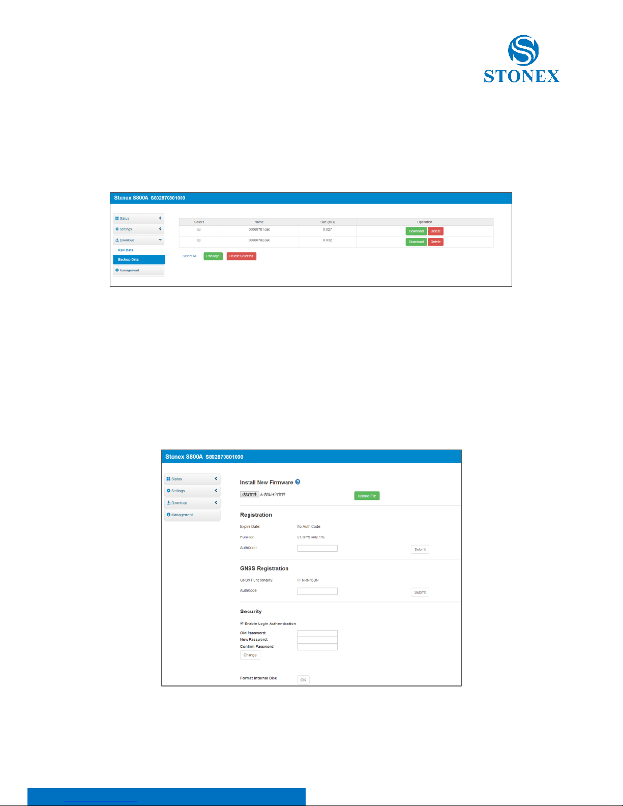
4.3 Download
In Download, it provides download of raw data and backups data. You can
see detailed information with respective tap as illustrated in Figure 4-3.
Figure 4-3 Backups data
4.4 Management
In Management, it provides online update, device register, password
modification, device disk formatting, self-test, restore factory settings and
reset as illustrated in Figure 4-4.
Figure 4-4 Management
Page 26

S800A GNSS Receiver – User Manual 25
4.4.1 Device Register
The register code consists of 32 digits and letters. You can register the device
via WEB UI. The detailed steps are shown as followed:
In management page, you can see “registration”. Input register code and
click submit, and then registration is done. After registration, you can check
the expiration time of current registration in the page.
You can also register device via controller. Open SurPad software on the
handheld and connect the receiver. Click “About” - “Register instrument”,
then input code and registration is done.
Page 27
S800A GNSS Receiver – User Manual 26
Appendix 1: S800A Receiver Specification
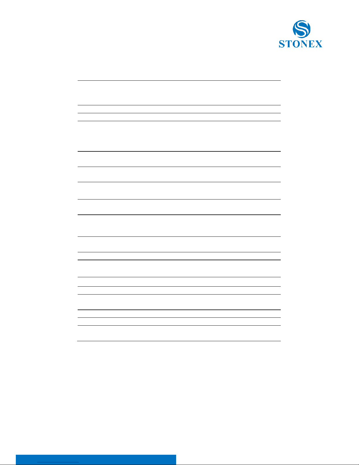
RECEIVER
GPS: L1 C/A, L1C, L1P, L2C, L2P, L5
GLONASS: L1 C/A, L1P, L2C, L2P
BEIDOU: B1, B2, B3
GALILEO: E1, E5a, E5b
QZSS: L1 C/A, L1C, L2C, L5
SBAS: L1, L5
L-Band
Atlas H10 / H30 / H100
Channels
394
Position Rate
5 Hz, optional up to 20 Hz
Signal Reacquisition
< 1 sec
RTK Signal Initialization
Typically < 10 sec
Hot Start
Typically < 15 sec
Initialization Reliability
> 99.9 %
Internal Memory
8 GB
POSITIONING
1
HIGH PRECISION STATIC SURVEYING
Horizontal
2.5 mm + 1 ppm RMS
Vertical
5.0 mm + 1 ppm RMS
CODE DIFFERENTIAL POSITIONING
Horizontal
<0.5 m RMS
Vertical
<1.0 m RMS
SBAS POSITIONING
Horizontal
<0.6 m RMS2
Vertical
<1.2 m RMS
2
REAL TIME KINEMATIC (< 30 Km) – NETWORK SURVEYING3
Fixed RTK Horizontal
8 mm + 1 ppm RMS
Fixed RTK Vertical
15 mm + 1 ppm RMS
INTEGRATED GNSS ANTENNA
High accuracy four constellation micro-strip antenna, zero phase
center, with internal multipath suppressive board
INTERNAL RADIO
Type
Tx - Rx
Frequency Range
410 - 470 MHz
Channel Spacing
12.5 KHz / 25 KHz
Maximum Range
3-4 Km in urban environment
Up to 10km with optimal conditions4
Page 28
S800A GNSS Receiver – User Manual 27
1. Accuracy and reliability are generally subject to satellite geometry (DOPs), multipath, atmospheric conditions and obstructions. In static
mode they are subject even to occupation times: the longer is the Baseline, the longer must be the occupation time.
2. Depends on SBAS system performance.
3. Network RTK precision depends on the network performances and are referenced to the closest physical base station.
4. Varies with the operating environment and with electromagnetic pollution.
5. S800A Polar Version.
COMMUNICATION
I/O Connectors
7-pins Lemo and 5-pins Lemo
interfaces. Multifunction cable with
USB interface for PC connection
Bluetooth
V2.0 Class2/V4.1LE
Wi-Fi
802.11 b/g
Web UI
To upgrade the software, manage the
status and settings, data download,
etc. via smart phone, tablet or other
internet enabled electronic device
Reference outputs
RTCM 2.3, 3.0, 3.1, 3.2
CMR, CMR+
Navigation outputs
GGA, ZDA, GSA, GSV, GST, VTG,
RMC, GLL
POWER SUPPLY
Battery
Rechargeable 7.2 V – 6800 mAh
Rechargeable 7.2 V – 5200 mAh5
Voltage
9 to 18 V DC external power input
with over-voltage protection
(5 pins Lemo)
Working Time
Up to 10 hours
Up to 8 hours5
Charge Time
Typically 4 hours
PHYSICAL SPECIFICATION
Dimensions
146 mm x 146 mm x 76 mm
Weight
1.2 Kg
Operating Temperature
-30°C to 65°C (-22°F to 149°F)
-40°C to 65°C (-40°F to 149°F)5
Storage Temperature
-40°C to 80°C (-40°F to 176°F)
Waterproof/Dustproof
IP67
Shock Resistance
Designed to endure to a 2 m pole drop on
concrete floor with no damage
Specifications are subject to change without notice.
Page 29
S800A GNSS Receiver – User Manual 28
Appendix 2: Default Radio Configuration
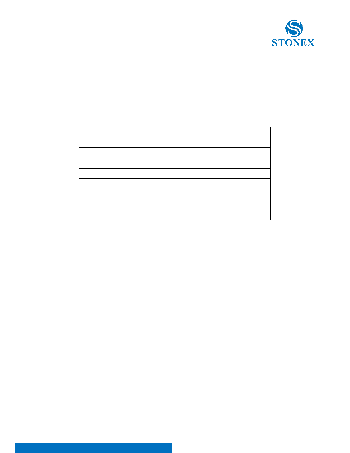
The S800A uses a single UHF radio to cover the different the whole band
410-470 MHz. The frequency and protocol can be easily modified via
controller.
Channel number
Frequency (MHz)
1
451.000
2
452.000
3
453.000
4
454.000
5
455.000
6
456.000
7
457.000
8
458.000
Page 30

S800A GNSS Receiver – User Manual 29
Appendix 3: Copyrights, warranty and environmental
recycling
Copyrights and trademarks
© 2017, STONEX® Limited. All rights reserved.
STONEX®, the STONEX® logo, and S800A GNSS receiver are trademarks of
STONEX® Limited.
STONEX® Assistant, STONEX® GPS Processor and STONEX® SurvCE are
trademarks of STONEX® Limited.
Bluetooth is a trademark owned by Bluetooth SIG, Inc. and licensed to
Trimble Navigation Limited. All other trademarks are the property of their
respective owners.
Release Notice
This is the May 2017 release of the STONEX® S800A GNSS new model
receiver user guide.
The following limited warranties give you specific legal rights. You may have
others, which vary from state/jurisdiction to state/jurisdiction.
Standard Limited Warranty
Version 2014
The terms and conditions of this Limited Warranty constitute the complete
and exclusive warranty agreement between The Customer or Dealer and
STONEX® for the Product and supersedes any prior agreement or
representation made in any STONEX® sales document or advice that may be
provided to Customer by any STONEX® representative in connection with
Customer’s purchase of the Product. No change to the conditions of this
Page 31

S800A GNSS Receiver – User Manual 30
Limited Warranty is valid unless it is made in written form and signed by an
authorized STONEX® supervisor.
STONEX® Europe warrants that its Products:
(1) are free from defects in materials or workmanship for generally 2 years.
a) accessories or specific parts for which different limited warranty
period shall apply.
(2) have been tested/calibrated in proper working status prior to shipment.
The warranty period starts from date of first sale of the instruments. At its
sole discretion, under the warranty period, STONEX® Europe will repair the
product or send parts for replacement at its expense. STONEX® Europe
agrees to repair or replace the defected instrument within thirty (30) days
only if STONEX® Europe recognizes that the defects of the instrument are
not caused by human factors or no obvious damage to its surface is visible.
STONEX® Europe warrants any new replaced parts or products are warranted
to be free from defects in materials and workmanship for thirty (30) days or
for the remainder of the Limited Warranty Period of the Product in which
they are installed, whichever is longer. Faulty Parts or Products replaced
under this Limited Warranty shall become property of STONEX® Europe. All
products that have to be repaired have to be returned to our technical
representative office location via any delivery company the customer prefers,
nevertheless STONEX® Europe is not accountable for the unlikely event that
the Products gets lost in transit. Any damage inflicted by the customer or by
third party after the products has been delivered to the customer is excluded
from the limited warranty as well any damage arising from an improper use,
from any action or use not provided for in the enclosed user guides and/or
manuals.
Page 32

S800A GNSS Receiver – User Manual 31
Shipping policy
The Customer or the dealer is required to pay for the charges for shipping of
fault parts or instruments to STONEX® Europe representative office and
STONEX® Europe is providing the shipping for return. Dealers need to follow
STONEX® Europe repair/service procedure to achieve a better and prompt
service result.
Return policy Dead On Arrival instruments.
All returned products have to be shipped to STONEX® Europe representative
office.
The original Purchaser has a period of seven (7) days starting from date of
purchasing to signal the existence of a defect in the instrument for a full
refund (less shipping and handling), provided the merchandise is in new,
resalable condition and returned in the original, undamaged packaging.
Customer has to pay for both the return and the original freight fees,
regardless of the original freight paid by the Company. All warranty books,
instruction manuals, parts and accessories must be included as well as the
original box in which the item was shipped. We recommend to place the
original carton inside another box, to avoid any additional damage to the
carton itself. In some cases, returns of special items will require a re-stock
fee. Acceptance of returned merchandise is final only after inspection by
STONEX® Europe.
Above terms and policies shall apply as for hardware. Dealers need to follow
STONEX® Europe repair/service procedure to achieve a better and prompt
service result.
Page 33

S800A GNSS Receiver – User Manual 32
Firmware/Software warranty.
Stonex Europe doesn’t warrant that operation of Firmware/Software on any
instruments will be uninterrupted or error-free, or that functions contained in
Firmware/Software will operate to meet your requirements.
Stonex will forward the Software/Firmware Fix to the dealer or customer.
Firmware/software Fix means an error correction or other update created to
fix a previous firmware version that substantially doesn’t conform to the
instruments specification.
Over Warranty repair(s) policy.
Customer shall pay the standard repair fees for any service (whether part
replacement or repairs) and performed by STONEX® Europe under request
and explicit authorization of the customer itself. In this case the customer is
charged for return shipment’s fees as well.
Disclaimer and Limitation of Remedy.
All other express and implied warranties for this product, including the
implied warranties of merchantability and fitness for a particular purpose
and/or noninf ringement of any third party’s rights, are hereby disclaimed.
Stonex® expressly disclaims all warranties not stated in this limited warranty.
Any implied warranties that may be imposed by law are limited in duration
to the term of this limited warranty. Some jurisdictions do not allow the
exclusion of implied warranties or limitations on how long an implied
warranty lasts, so the above exclusions or limitations may not apply to
customer. Customer must read and follow all set-up and usage instructions
in the applicable user guides and/or manuals enclosed. If customer fails to
do so, this product may not function properly and may be damaged.
Customer may lose data or sustain personal injuries. Stonex®, its affiliates
and suppliers do not warrant that operation of this product will be
Page 34

S800A GNSS Receiver – User Manual 33
uninterrupted or error free; as do all electronics at times. If this product fails
to work as warranted above, customer’s sole and exclusive remedy shall be
repair or replacement. In no event will stonex®, its affiliates or suppliers be
liable to customer or any third party for any damage in excess of the
purchase price of the product. This limitation applies to damages of any kind
whatsoever including (1) damage to, or loss or corruption of, customer’s
records, programs, data or removable storage media, or (2) any direct or
indirect damages, lost profits, lost savings or other special, incidental,
exemplary or consequential damages, whether for breach of warranty,
contract, tort or otherwise, or whether arising out of the use of or inability to
use the product and/or the enclosed user guides and/or manuals, even if
stonex?, or an authorized stonex® representative, authorized service provider
or reseller has been advised of the possibility of such damages or of any
claim by any other party. Some jurisdictions do not allow the exclusion or
limitation of incidental or consequential damages for some products, so the
exclusions or limitations may not apply to customer. This limited warranty
gives customer specific legal rights, and customer may also have other rights
which vary from country/state/jurisdiction to country/state/
Instruments
Two (2) years on STONEX® Products:
GPS receiver: S800A GNSS Series
Page 35

S800A GNSS Receiver – User Manual 34
Accessories
Accessories & Specific Parts Warranty:
For Accessories provided by Stonex with the instruments S800A GNSS the
following general warranty time is for reference:
Batteries: 7 months.
Battery chargers: 7 months.
Adapters for battery chargers, Cables, Tribrach, Pole, Antennas: 2
years.
Service Procedure
Repair/Service procedure for dealers.
(1) S/N of the instrument and a detailed description of the defect (sometimes
pictures or video) will be required to indicate the cause and problem.
(2) If dealer wants to repair an instrument under warranty period on their
site:
1) If dealers don’t have the part in stock they have to send an official order
to STONEX® Europe and pay for it and so STONEX® Europe will send the
new part to them so they can repair the instrument.
2)When the repair is over, the dealer has to fill the “Spare Part Refund”
module and send it to the dedicated mail address.
3) wait for STONEX® Europe’s authorization SPR no;
4) when dealer receive the SPR authorization no they can send back to
STONEX® Europe appointed office the broken part with attached the SPR
module;
Page 36

S800A GNSS Receiver – User Manual 35
5) when STONEX® Europe receives the broken part STONEX® Europe shall
verify it and if everything is ok the cost of the part shall be refund (refund
will be done only after check of the failure part and final approval of
STONEX® Europe).
(3) If the instrument needs to be sent back to STONEX® Europe for
repair/replacement, dealer/customer has to send to STONEX® Europe a
“Returned Merchandise Authorization (RMA)” before they send back the fault
instrument. STONEX® Europe shall, at its sole discretion, decide on the place
of performance for work under warranty.
Environmental recycling
The cardboard box, the plastic in the package and the various parts of this
product have to be recycled and disposed of in accordance with the current
legislation of your Country.
For countries in the european union (eu)
The disposal of electric and electronic device as solid urban waste is strictly
prohibited: they must be collected separately.
Contact Local Authorities to obtain practical information about correct
handling of the waste, location and times of waste collection centre. When
you buy a new device of ours, you can give back to our dealer a used similar
device.
The dumping of these devices at unequipped or unauthorized places may
have hazardous effects on health and environment.
The crossed dustbin symbol means that the device must be taken to
authorize collection centers and must be handled separately from solid
urban waste.
Page 37

S800A GNSS Receiver – User Manual 36
·
For countries outside european union (eu)
The treatment, recycling, collection and disposal of electric and electronic
devices may vary in accordance with the laws in force in the Country in
question.
Page 38

S800A GNSS Receiver – User Manual 37
Appendix 4: Safety Recommendations
Warnings and Cautions
An absence of specific alerts does not mean that there are no safety risks
involved in the use of this equipment.
Always follow the instructions that accompany a Warning or Caution,
reported in this.
This information are intended to minimize the risk of personal injury and/or
damage to propriety. In particular, observe safety instructions that are
presented in the following form:
WARNING - A Warning alerts about risk for health and/or damage to the
propriety. A warning identifies the nature of the risk and the extent the possible
injury and/or damage. It also describes how to protect yourself and/or the
equipment from this risk.
CAUTION - A Caution alerts about a possible risk of damage to the equipment
and/or loss of data, but no risk for human safety.
Wireless Module Approval
The receivers uses internal wireless modules or can be connected to an
external data communications UHF radio. Regulations regarding the use of
the radio-modems vary greatly from country to country. In some countries,
the unit can be used without obtaining an approval license. Other countries
require specific approval or auto certification by the set maker.
Before using this instrument , check if authorization to operate the receiver
is required in your country. It is the responsibility of the importer to verify if
it is necessary a certification or license for the equipment in the country of
use.
Instrument Approval
Covers technical features of the equipment relatives to electromagnetic
emissions that can cause interference and disturbances to other instruments
(note like emc compatibility) or generate not correct functionalities of the
instrument itself. Approval is granted by the manufacturer of the equipment.
Some countries have unique technical requirements for operation in
particular frequency bands. To comply with those requirements, Stonex srl
may modified the equipment to be subjected to grant.
Page 39
S800A GNSS Receiver – User Manual 38
Unauthorized modification of the units voids already got approvals, the
warranty time and the operational licenses of the instrument.
UHF 410-470 MHz Data transceiver
General Antenna Installation Warning
1. All antenna installation and servicing is to be performed by qualified
technical personnel only. When servicing the antenna, or working at
distances closer than those listed below, ensure the transmitter has been
disabled.
2. Typically, the antenna connected to the transmitter is a directional (high
gain) antenna, fixed-mounted on the side or top of a building, or on a tower.
Depending upon the application and the gain of the antenna, the total
composite power could exceed 90 watts ERP. The antenna location should be
such that only qualified technical personnel can access it, and that under
normal operating conditions no other person can touch the antenna or
approach within 0.6 meters of the antenna.
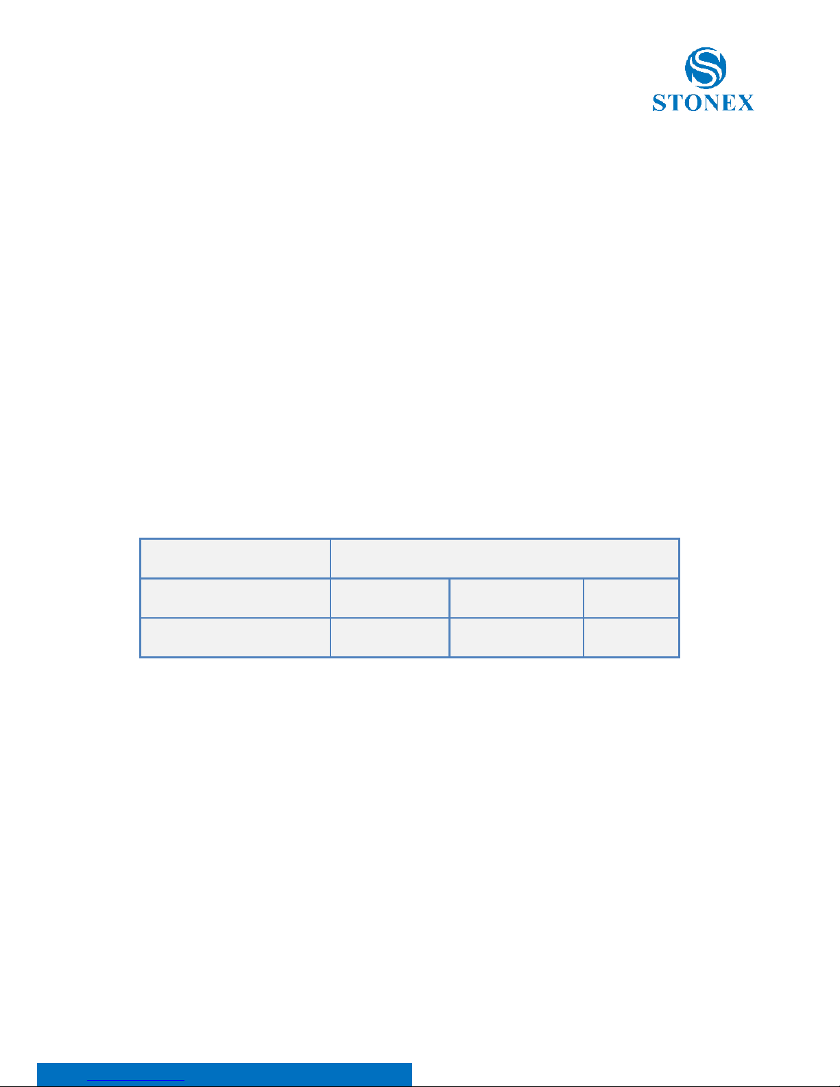
You can see below a table showing the Antenna Gain versus Recommended
Safety Distance:
Antenna Gain
0-5 dBi
5-10 dBi
10-16.5 dBi
Minimum RF safety distance
0.6 meters
1.06 meters
2.3 meters
For USA: The FCC has adopted a safety standard for human exposure to
radio frequency electromagnetic energy. Proper use of this radio modem
results in exposure below government limits. The following precautions are
recommended:
DO NOT operate the transmitter when someone is located less than 20 cm
(7.8 inches) of the antenna.
DO NOT collocate (place within 20 cm) the radio antenna with any other
transmitting instruments.
DO NOT operate the transmitter unless all RF connectors are secure and any
open connectors are properly terminated.
Page 40

S800A GNSS Receiver – User Manual 39
DO NOT operate the equipment near electrical blasting caps or in an
explosive atmosphere.
All equipment must be properly used according to the installation
instructions for safe operation.
All equipment should be repaired and calibrated only by a qualified
technician.
For Europe
The European Community provides some Directives for the electronic
equipments introduced on the market.
All the relevant information’s are available on the European Community
website:
http://ec.europa.eu/enterprise/sectors/rtte/documents/
The text of the Directive 99/05 regarding telecommunication equipments is
available, while the applicable Directives (Low Voltage and EMC) are available
at:
http://ec.europa.eu/enterprise/sectors/electrical
FOR USA
For your own safety, and in terms of the RF Exposure requirements of the
FCC always observe the precautions listed here.
• Maintain a minimum separation distance of 20 cm (7.8
inches) between yourself and the radiating antenna.
• Do not collocate (place within 20 cm) the radio antenna
with any other transmitting device.
Bluetooth/WiFi radio Module
The radiated output power of the internal Bluetooth module of this
equipment is far below the FCC and EU radio frequency exposure limits. In
Page 41

S800A GNSS Receiver – User Manual 40
any case, be sure to use the equipment with the radio far at least 20 cm from
the human body. The Bluetooth module match the guidelines found in radio
frequency “safety standards and recommendations “published by Scientific
organizations.
Stonex srl therefore believes the internal wireless radio is safe for use by end
users. The level of energy emitted is far less than the electromagnetic energy
emitted by wireless devices such as UMTS phones. However, the use of
Bluetooth/WiFi may be restricted in some special situations or place , like
aircraft , hospital ,etc. If you are unsure of existence of restrictions, you
should ask for authorization before switching on the Bluetooth radio.
Raccomandation for installing antennas for internal radios
An absence of specific alerts does not mean that there are no safety risks
involved in the use of this equipment.
Always follow the instructions that accompany a Warning or Caution,
reported in this. This information are intended to minimize the risk of
personal injury and/or damage to propriety. In particular, observe safety
instructions that are presented in the following form:
CAUTION
For your own safety, and to match the RF Exposure requirements of the FCC, always
observe these precautions:
- Always maintain a minimum separation distance of 20 cm (7.8 inches)
between yourself and the radiating antenna.
- Do not collocate (place within 20cm) the radio antenna with any other
transmitting device.
- Do not switch on the GSM or UHF module without the antenna mounted
to the external connector.
UHF Antennas having a gain greater than 5 dBi, are strictly prohibited for use
with this device. The required antenna impedance must be 50 ohms.
Rechargeable Lithium-ion batteries
These receivers use a rechargeable Lithium-ion battery.
Page 42

S800A GNSS Receiver – User Manual 41
WARNING
- Do not creates damage at the rechargeable Lithium-ion battery.
A damaged battery can cause an explosion, with risk or fire, and can result in
personal injury and/or property damage.
To prevent injury or damage:
– Do not use or charge the battery if it appears to be damaged. Signs of damage are
discoloration, warping, leaks of liquids.
– Do not expose the battery to fire, high temperature, or direct strong sunlight.
– Do not introduce the battery in water or liquid substance , in general.
– Do not use or store the battery in very hot ambient.
– Do not drop or puncture the battery.
– Do not open the battery and do not put in short-circuit its electrical contacts.
WARNING
- Avoid direct contact with the rechargeable Lithium-ion battery if it appears
damage. Battery liquids are corrosive and, and contact with it can result in personal
injury or damage to proprieties.
To prevent injury or damage:
– If the battery leaks, avoid contact with the battery fluid.
– If battery fluid gets into your eyes, immediately rinse your eyes with clean water
and seek medical attention. Do not rub your eyes!
– If battery fluid gets onto your skin or clothing, immediately use clean water to wash
off the battery fluid.
Page 43

S800A GNSS Receiver – User Manual 42
STONEX® SRL
Via Cimabue, 39 - 20851 Lissone (MB)
Tel: +390392783008 ; +390392785575 | Fax :+390392789576
www.stonexpositioning.com | [email protected]
 Loading...