

Page 1

STONEX R2
1
CONTENT
FOREWORDS ............................................................................................................... 1
1. NOMENCLATURE AND FUNCTIONS ............................................................... 4
1.1 NOMENCLATURE (take R2 as example in the full text) ........................ 4
1.2 DISPLAY .................................................................................................. 6
1.4 FIXED KEYS ............................................................................................ 7
1.5 TRIGGER KEY ........................................................................................ 7
1.6 SOFT KEYS(FUNCTIONAL KEYS) ................................................. 7
1.7 SYMBOLS ................................................................................................ 8
1.8 ICONS ....................................................................................................... 8
1.9 MENU TREE ............................................................................................ 9
1.10 AUTO POWER OFF ............................................................................. 10
2. PREPARATION FOR MEASUREMENT ............................................................ 11
2.1 UNPACKING AND STORE OF INSTRUMENT .................................. 11
2.2 INSTRUMENT SETUP .......................................................................... 11
2.3 BATTERY POWER REMAINING DISPLAY ....................................... 13
2.4 REFLECTOR PRISMS ........................................................................... 14
2.5 MOUNTING AND DISMOUNTING INSTRUMENT FROM TRIBRACH .......... 15
2.6 EYEPIECE ADJUSTMENT AND COLLIMATING OBJECT .............. 15
2.7 INPUTTING MODE ............................................................................... 16
2.7.1 Inputting Character ................................................................................... 17
2.7.2 Editing Character ...................................................................................... 18
2.7.3 Deleting Character .................................................................................... 18
2.7.4 Inserting Character ................................................................................... 19
2.8 POINT SEARCH .................................................................................... 20
2.9 WILDCARD SEARCH ........................................................................... 22
3. ROUTINE MEASUREMENT .............................................................................. 23
3.1 DISTANCE SURVEY CAUTIONS ........................................................ 23
3.2 EDM SETTINGS .................................................................................... 24
3.2.1 Setting EDM Mode .................................................................................. 24
3.2.2 Setting Distance Measurement Type ........................................................ 25
3.2.3 Setting the Prism Constant ....................................................................... 26
3.2.4 Setting Atmosphere Data .......................................................................... 27
3.2.5 Grid Factor ............................................................................................... 30
3.2.6 Viewing Signal of Distance Measurement ............................................... 31
3.2.7 Setting Multiplication Constant ................................................................ 32
3.3 START SURVEY .................................................................................... 33
3.3.1 Setting Horizontal Circle .......................................................................... 33
Page 2

STONEX R2
2
3.3.2 Setting the Instrument Height and Prism Height ...................................... 35
3.3.3 Measurement ............................................................................................ 36
3.3.4 Coding ...................................................................................................... 37
3.3.5 Quick Code ............................................................................................... 41
4. FUNCTIONS ........................................................................................................ 43
4.1 LEVELING ............................................................................................. 44
4.2 TARGET OFFSET .................................................................................. 45
4.3 DELETING LAST RECORD ................................................................. 47
4.4 MAIN SETTINGS .................................................................................. 48
4.5 HEIGHT TRANSFER ............................................................................. 52
4.6 HIDDEN POINT MEASUREMENT ...................................................... 56
4.7 CHECKING TIE ..................................................................................... 58
4.8 TRACKING ............................................................................................ 60
5. PROGRAMS ......................................................................................................... 60
5.1 SETTING JOB ........................................................................................ 61
5.1.1 Setting a New Job ..................................................................................... 61
5.1.2 Calling up a Job from Internal Memory ................................................... 62
5.2 SETTING STATION ............................................................................... 63
5.2.1 Calling up a Job from Internal Memory-[SEARCH] ............................... 64
5.2.2 Calling up Known Point in Internal Memory-[LIST]............................... 65
5.2.3 Inputting Coordinate Manually ................................................................ 67
5.3 SETTING ORIENTATION ..................................................................... 67
5.3.1 Manually Inputting ................................................................................... 68
5.3.2 with Coordinates....................................................................................... 69
5.3.3 Displaying Residuals ................................................................................ 74
5.4 APPLICATIONS ..................................................................................... 75
5.5 SURVEYING .......................................................................................... 76
5.5.1 Individual Point ........................................................................................ 77
5.5.2 Coding ...................................................................................................... 79
5.6 STAKING OUT ...................................................................................... 79
5.6.1 Setting Stake-Out Point ............................................................................ 79
5.6.1.1 Calling up Coordinates from job. .......................................................... 79
5.6.1.2 Inputting Coordinate Manually ............................................................. 81
5.6.2 Polar Stake Out ......................................................................................... 83
5.6.3 Orthogonal Stake Out ............................................................................... 85
5.6.4 Coordinate Offset Stake Out..................................................................... 87
5.6.5 B & D ....................................................................................................... 89
5.7 FREE STATION ...................................................................................... 91
5.8 COGO...................................................................................................... 95
Page 3

STONEX R2
3
5.8.1 Inverse & Traverse ................................................................................... 96
5.8.1.2 Inverse ................................................................................................. 100
5.8.2 Intersections ........................................................................................... 101
5.8.2.1 Bearing-Bearing .................................................................................. 101
5.8.2.2 Bearing-Distance Intersection ............................................................. 103
5.8.2.3 Distance-Distance Intersection ............................................................ 105
5.8.2.4 By Points ............................................................................................. 106
5.8.3 Offset ...................................................................................................... 108
5.8.3.1 Distance-Offset .................................................................................... 108
5.8.3.2 Point-Offset ......................................................................................... 110
5.8.4 Extension ................................................................................................ 111
5.9 TIE DISTANCE .................................................................................... 113
5.9.1 Polygonal (A-B, B-C) ............................................................................. 113
5.9.2 Radial (A-B, A-C) .................................................................................. 116
5.10 AREA MEASUREMENT (PLANE) ................................................... 118
5.11 REMOTE HEIGHT MEASUREMENT (REM) ................................. 121
5.12 ROAD.................................................................................................. 124
5.12.1 Define HZ Alignment ........................................................................... 124
5.12.2 Editing Horizontal Alignment Data ...................................................... 130
5.12.3 Deleting Horizontal Alignment Data .................................................... 132
5.12.4 Defining Vertical Alignment ................................................................. 133
5.12.5 Editing Vertical Alignment Data........................................................... 134
5.12.6 Deleting Vertical Alignment Data......................................................... 135
5.12.7 Road Stake-Out .................................................................................... 136
5.12.8 Slope Stake-Out .................................................................................... 142
5.13 CONSTRUCTION SITE STAKE OUT .............................................. 144
5.13.1 Defining New Construction Site .......................................................... 144
5.13.2 Shifting Line ......................................................................................... 147
5.13.3 As Build Check ..................................................................................... 148
5.13.4 Stake Out .............................................................................................. 149
6. FILE MANAGEMENT ...................................................................................... 151
6.1 JOB ........................................................................................................ 151
6.1.1 Selecting Job .......................................................................................... 151
6.1.2 Establishing New Job ............................................................................. 152
6.1.3 Deleting Selected Job ............................................................................. 154
6.2 KNOWN POINT ................................................................................... 154
6.2.1 Searching Known Points ........................................................................ 155
6.2.2 Adding Known Point .............................................................................. 155
6.2.3 Editing the Known Points ....................................................................... 157
Page 4

STONEX R2
4
6.2.4 Deleting Known Points .......................................................................... 158
6.3 MEASUREMENT DATA ..................................................................... 158
6.3.1 Viewing Measurement Data ................................................................... 158
6.3.2 Deleting Measurement Data ................................................................... 162
6.4 CODING ............................................................................................... 162
6.4.1 Manual Code Input ................................................................................. 163
6.4.2 Viewing Code ......................................................................................... 164
6.4.3 Deleting Code ......................................................................................... 165
6.5 INTIALIZING INTERNAL MEMORY ............................................... 166
6.6 MEMORY STATISTIC ......................................................................... 167
7. COMMUNICATION SETTING ......................................................................... 168
8. DATA TRANSFER ............................................................................................. 170
9. SYSTEM INFORMATION ................................................................................ 171
10.EXPORT/IMPORT DATA ................................................................................. 172
11. SEND/RECEIVE DATA BY USB .................................................................... 174
12.U DISK MODE(MEMORY MODE) ................................................................. 177
13. CHECK AND ADJUSTMENT ......................................................................... 179
13.1 PLATE VIAL ...................................................................................... 179
13.2 CIRCULAR VIAL .............................................................................. 179
13.3 INCLINATION OF RETICLE ............................................................ 180
13.4 PERPENDICULARITY BETWEEN LINE OF SIGHT AND
HORIZONTAL AXIS (2C) ..................................................................................... 181
13.5 VERTICAL INDEX DIFFERENCE COMPENSATION ................... 182
13.6 ADJUSTMENT OF VERTICAL INDEX DIFFERENCE (I ANGLE)
AND SETTING VERTICAL INDEX O ................................................................. 183
13.7 TRANSVERSE AXIS ERROR COMPENSATION ADJUSTMENT 184
13.8 PLUMMET ......................................................................................... 186
13.9 INSTRUMENT CONSTANT (K) ....................................................... 188
13.10 PARALLEL BETWEEN LINE OF SIGHT AND EMITTING
PHOTOELECTRIC AXIS ...................................................................................... 190
13.11 REFLECTORLESS EDM ................................................................. 190
13.12 TRIBRACH LEVELING SCREW ................................................... 191
13.13 RELATED PARTS FOR REFLECTOR ............................................ 191
14.SPECIFICATION............................................................................................ 192
15. ACCESSORIES ................................................................................................ 195
【APPENDIX-A】DATA COMMUNICATION ................................................... 196
【APPENDIX-B】 CALCULATE ROAD ALIGNMENT ................................... 211
Page 5

STONEX R2
1
FOREWORDS
Congratulations on the purchase of STONEX Total Station R Series.
This manual is for the application of STONEX Total Station R Series.
STONEX R2 Total Station is equipped with infrared laser optic-electronic distance
meter.
STONEX R2 Total Station is equipped with visible infrared laser distance meter
which is operated without sighting a reflector.
In this manual, the parts which are marked “ ” are only applicable to STONEX
R2. Before operating the instrument, please read this manual carefully.
FEATURES:
1. Powerful Software Functions
The internal software installed in STONEX R SeriesTotal Station is precisely designed. It
boasts of compact menu structure and complete and practical application programs, which
proves efficient and helpful in the process of project measurement and stake-out.
2. Simplified Operation
STONEX R Series Total Station has various functional keys, coupled with an input mode
combining characters and numbers perfectly. It‟s simple, practical, and convenient in use,
which enables the engineers who don‟t even have too much surveying experience to
master the operation quickly.
3. Absolute Encoding Circle
The pre-assembled Absolute Encoding Circle enables the user to start measurement
directly after switching on the instrument. Even if the user replaces the battery during
operation, the azimuth data will not be deleted.
4. Reflectorless EDM
The reflectorless laser EDM function equipped in Total Station R Series can be operated
the measurement on various materials of different colors (such as the wall surface of
constructions, telegraph pole, wire, cliff, hill and mountain, earth and soil, stump) from
long distance with high precision. It brings great convenience to surveyors when
measuring a target that is hard or even impossible to reach.
5. High Precision and Long Measuring Range
The measuring range of STONEX R Series Total Station is 2.4 km with single prism.
6. Reliable Water and Dust Proof Function
R Series Total Station boasts water and dust proof function, which realizes a breakthrough
in terms of the hardware performance of total station.
Page 6

STONEX R2
2
PRECAUTIONS
1. Do not collimate the objective lens direct to sunlight without a filter.
2. Do not store the instrument in high and low temperature to avoid the sudden or great
change of temperature.
3. When the instrument is not in use, place it in the case and avoid shock, dust and
humidity.
4. If there is great difference between the temperature in work site and that in store place,
you should leave the instrument in the case till it adapts to the temperature of
environment.
5. If the instrument has not been used for a long time, you should remove the battery for
separate storage. The battery should be charged once a month.
6. When transporting the instrument should be placed in its carrying case, it is
recommended that cushioned material should be used around the case for support.
7. For less vibration and better accuracy, the instrument should be set up on a wooden
tripod rather than an aluminum tripod.
8. Clean exposed optical parts with degreased cotton or lens tissue only!
9. Clean the instrument surface with a woolen cloth after use. If it gets wet, dry it
immediately.
10. Before working, inspect the power, functions and indications of the instrument as well
as its initial settings and correction parameters.
11. Unless the user is a maintenance specialist, do not attempt to disassemble the
instrument by yourself even if you find the instrument abnormal.
12. Since Reflectorless Total Station R2 emits visible laser, do not sight the eyes in
use.
SAFETY GUIDE
Internal EDM (Visible Laser)
Warning:
The total station is equipped with an EDM of a laser grade of 3R/Ⅲa. It is verified by the
following labels.
On the vertical tangent screw sticks an indication label “CLASS III LASER PRODUCT”.
A similar label is sticked on the opposite side.
This product is classified as Class 3R laser product, which accords to the following
standards.
IEC60825-1:2001 “SAFETY OF LASER PRODUCTS”.
Class 3R/Ⅲ a laser product: It is harmful to observe laser beam continuously. User
should avoid sighting the laser at the eyes. It can reach 5 times the emitting limit of
Class2/II with a wavelength of 400mm-700mm.
Warning:
Page 7

STONEX R2
3
Continuously looking straight at the laser beam is harmful.
Prevention:
Do not stare at the laser beam, or point the laser beam to others‟ eyes. Reflected laser
beam is a valid measurement to the instrument.
Warning:
When the laser beam emits on prism, mirror, metal surface, window, etc., it is dangerous
to look straight at the reflex.
Prevention:
Do not stare at the object which reflects the laser beam. When the laser is switched
on (under EDM mode), do not look at it on the optical path or near the prism. It is only
allowed to observe the prism with the telescope of total station.
Warning:
Improper operation on laser instrument of Class 3R will bring dangers.
Prevention:
To avoid to be harmed, each user is required to take safety precautions, and take
everything under control within the distance that would incur dangers (according to
IEC60825-1:2001).
The following shows the explanation related to the key sections of the Standard.
Laser instrument of Class 3R is applicable outdoors and in construction field
(measurement, defining lines, leveling).
a) Only those persons who are trained with related course and authenticated are allowed
to install, adjust, and operate this kind of laser instrument.
b) Stand related warning symbols in the scale of use.
c) Prevent any person to look straight at or use optical instrument to observe the laser
beam.
d) To prevent the harm caused by laser, block the laser beam at the end of the working
route. When the laser beam exceeds the limit area (harmful distance*) and when there are
motivating persons, stopping the laser beam is a must.
e) The optical path of the laser should be set higher or lower than the line of sight.
f) When the laser instrument is not in use, take care of it properly. The person who is not
authenticated is not allowed to use.
g) Prevent the laser beam from irradiating plane mirror, metal surface, window, etc.
especially beware of the surface of plane mirror and concave mirror.
* Harmful distance means the maximum distance between the start point and the point
which the laser is weakened to a degree that doesn‟t harm people.
The internal EDM instrument equipped with a Class 3R/III a Laser has a harmful distance
of 1000m (3300ft). Beyond this distance, the laser intensity is weakened to Class I
(Looking straight at the laser beam causes no harm to the eyes.)
Page 8
STONEX R2
4
1. NOMENCLATURE AND FUNCTIONS
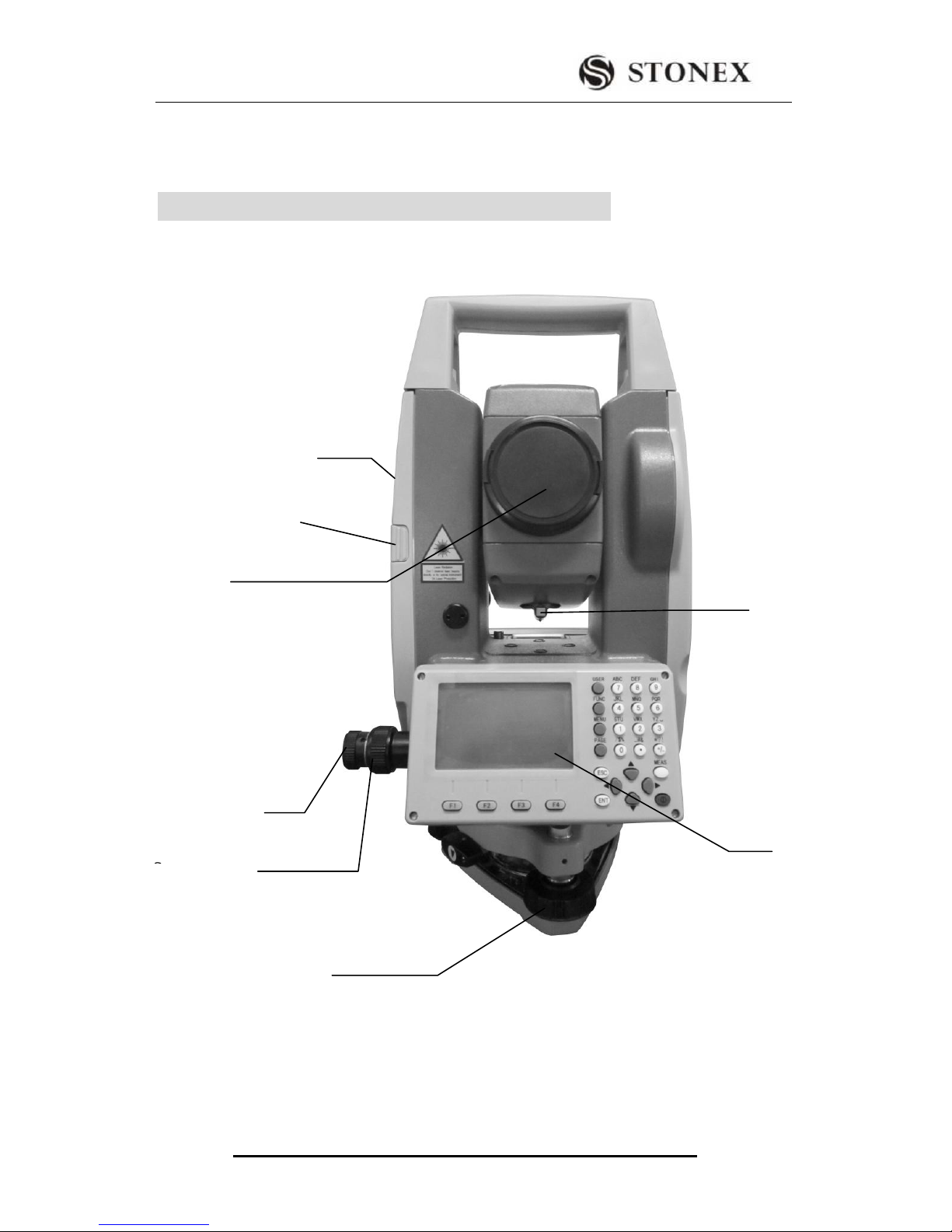
1.1 NOMENCLATURE (take R2 as example in the full text)
Collimator
Objective
Lens
Display
Leveling Screw
Battery
Battery Locking Lever
Horizontal Clamp
Screw
Horizontal
Tangent
Page 9
STONEX R2
5
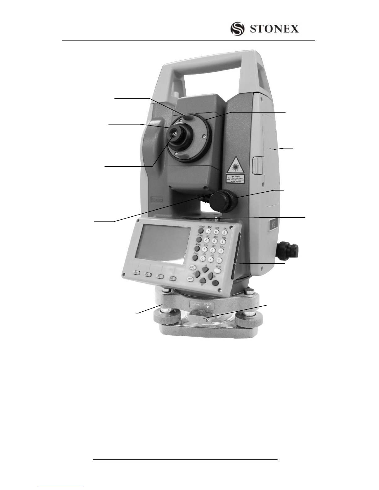
Telescope
Focusing Knob
Instrument
Center Mark
Telescope
Focusing
Knob
Eyepiece
Base
USB port and
SD Port
Telescope Grip
Tribrach Lock
VerticalClamp
Screw
Vertical Tangent
Plate Vial
Page 10
STONEX R2
6
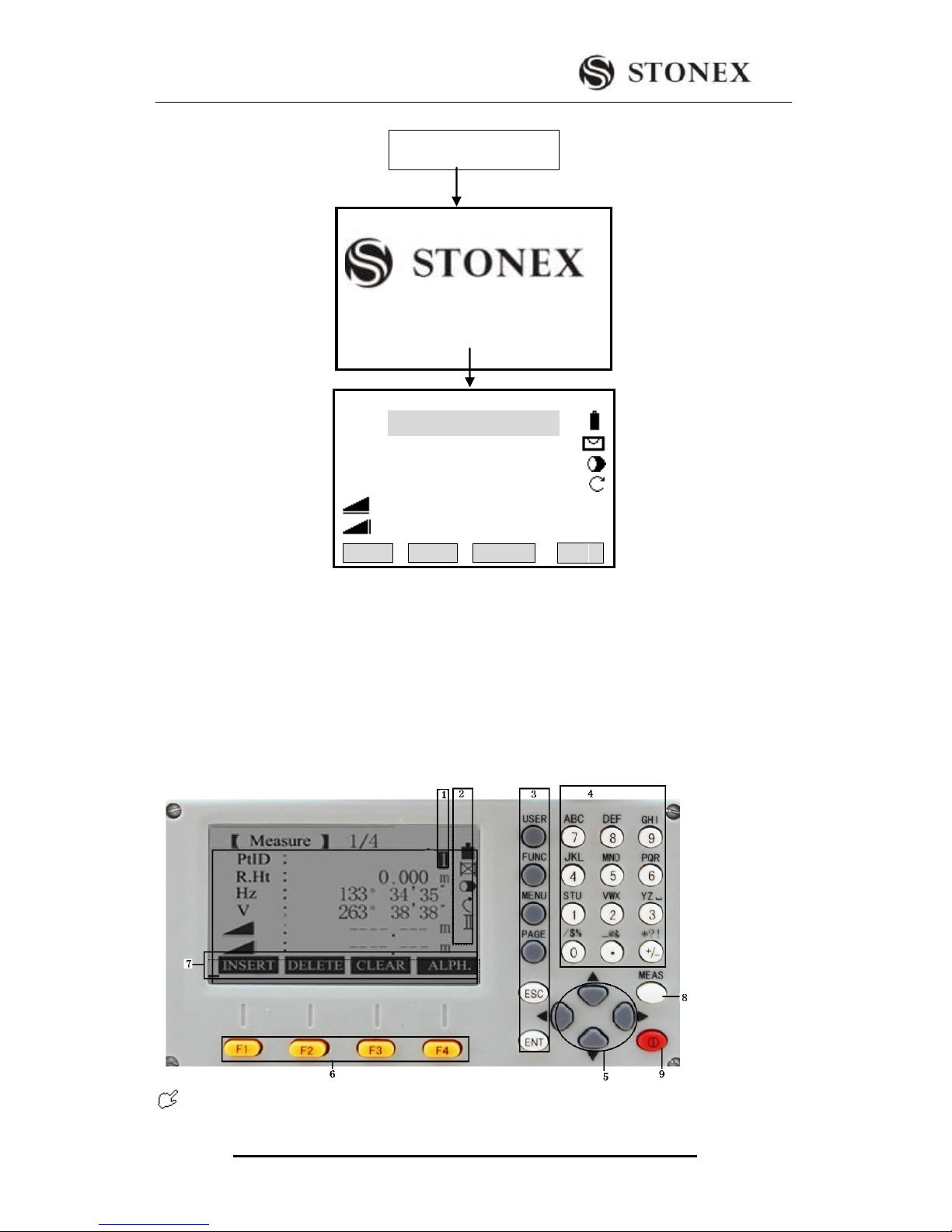
1.2 DISPLAY
Main Menu
Confirm the battery enough shown on the display. Replace it with another charged battery
or charge it when battery level is low. Refer to section 2.3 “Battery Power Remaining
Display”.
The chart above is the display screen. It is possible that local software versions are
different from the basic version.
1.3KEYPAD
It takes R2 for example here.
Power Switch Key ON
Model :R2
Number :RS4502
Version:11.06.29
【Measure】 1/4
PtID: A1
R.HT: 1.500 m
HR: 0°00′00″
V : 90°00′00″
: ---.--- m Ⅰ
: ---.--- m
All DIST RECORD ↓
Page 11
STONEX R2
7
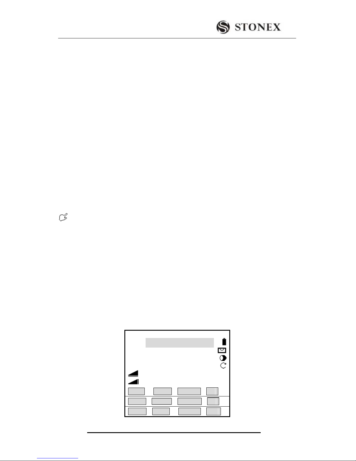
1) Focus (Actively measured field)
2) Icons
3) Fixed keys (Keys with firmly assigned functions)
4)Alphanumeric keys
5) Navigation keys (Control of input bar in edit and input mode or control of focus bar.)
6) Soft keys (Are assigned the variable functions displayed at the bottom of the screen.)
7) Soft bar (Displays functions that can be called up with the Soft keys. It can use to start
up figure and character input function in R Series.)
8) Trigger key (important key)
9) Power key
1.4 FIXED KEYS
[User]: User key can be defined. Programmable with function from the “Function” menu.
[FNC]: Measurement key in common use. Several functions could be called up, the
instructions are as follows:
²function could be started up directly in different application.
²every function in menu could be appointed to user key (see“4.4 MAIN SETTINGS”)
[Menu]: Menu key. Accesses to programs, settings, data manager, communication
parameters, instrument adjustments, system information and data transfer, etc.
In menus with multiple entries a shortcut number is shown on the right of each entry.
Using this number allows a direct start without turning page.
[PAGE]: Page key. Turn to next page when a dialogue consists of several pages.
[ESC]: Quit a dialog or the edit mode with activation of the “previous” value. Return to a
higher level.
[ENT]: Confirm an input, continue to the next field.
1.5 TRIGGER KEY
The measurement trigger (important key) has three settings (ALL, DIST, OFF). The key
can be activated in Settings or Main Settings menu.
1.6 SOFT KEYS(FUNCTIONAL KEYS)
The measurement data is displayed in the
several upper lines of the display, while a
selection of commands and
functions is at the bottom of the screen,
which can be activated with
corresponding functional keys. The
【Measure】 1/4
PtID : A1
R.HT: 1.500m
HR: 0°00′00″
V: 90°00′00″
: ---.--- m Ⅰ
: ---.--- m
ALL DIST RECORD ↓
SetStn EDM ↓
Set Hz TILT BEEP ∣←
Page 12
STONEX R2
8
meaning of each soft key depends on the applications/functions currently active.
Soft Keys:
Key
Function
[All]
Starts angle and distance measurements, and saves
measured values.
[DIST]
Starts angle and distance measurements without saving
measured values.
[REC]
Saves displayed values.
[ENH]
Opens the coordinate input mode
[List]
Displays the list of available points
[Search]
Starts the search for the input points
[EDM]
Displays EDM settings
[Esc]
Returns to the previous mode or display.
[Con]
Continues to next mode or display.
[ ]
Returns to highest soft key level.
[ ↓ ]
To next soft key level.
[ENT]
Sets displayed message or dialog and quits the dialog.
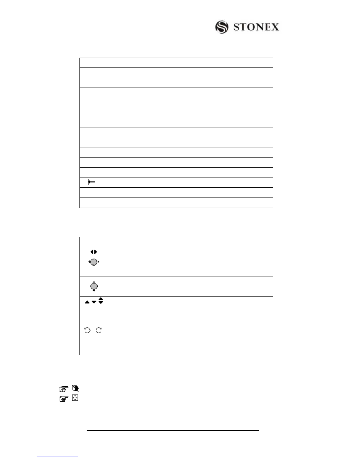
1.7 SYMBOLS
Symbol indicates a particular operating status depending on different software versions.
Key
Content
A double arrow indicates choice fields.
Using the navigation keys the desired parameter can be
selected.
Quits a selection with the navigation keys or Enter key.
, ,
Indicates that several pages are available which can be
selected with [PAGE].
Ⅰ,Ⅱ
Telescope (alidade) is at FaceⅠor FaceⅡ.
( )
Hz is set to “left angle measurement”(or right angle
measurement), which is to circumrotate anticlockwise
(clockwise)
1.8 ICONS
Measurement mode icons:
Infrared EDM (invisible) for measuring prisms and reflective targets.
Reflectorless EDM (visible) for measuring all targets.
Use reflective foils as reflective targets.
Battery capacity status icon:
Page 13

STONEX R2
9
The battery symbol indicates the level of the remaining battery capacity (80% full
shown in the example).
Compensator status icons:
Compensator is ON
Compensator is OFF
Character/Number inputting mode icons:
01 Numeric Mode
AB Alphanumeric Mode
1.9 MENU TREE
[Menu]>F1-F4 is to confirm the selected menu. Press [PAGE] to view the next page.
Menu tree may be different in the order of display.
MENU (P1)
Programs -----------Surveying
----Stake Out
----Free Station
----COGO
----Tie Distance
----Area (plan)
----Remote Height
----Reference Line/Arc
----Roads
----Construction by axes method
Settings -----------Contrast, Trigger Key, User Key, V- Setting,
Tilt Crn, Coll. Crn.
----SectorBeep, Beep,Hz<=>, Face l Def., Data Output, Auto-Off
---- MinReading, Angle Unit, Dist.Unit, Temp.Unit, Press Unit,
Code Rec.
----GSI 8/16, Mask 1/2
EDM Settings ----------EDM Mode
----Prism
----Atmospheric Data
----Grid Factors
----Signal
----Multiply Constant
File Management --------Job
Page 14

STONEX R2
10
----Known points
----Measurements
----Codes
----Initialize Memory
----Memory Statistic
MENU (P2)
Adjustment ----------------V- index
----Hz-collimation
----Horizontal Axis
----VO/Axis (Cons, list)
----lnst.Constant
----Tilt Parameter
----State
Comm Parameters ------Baudrate
----DataBits
----Parity
----End Mark
----Stop Bit
Data Transfer ------------Data Send ---- Job
---- Data
---- Format
System Information ------------Battery
----Date
----Time
----Version
----Type
----Number
1.10 AUTO POWER OFF
If no key operation is done for the setting time (30 minutes), the power turns off
automatically.
Page 15
STONEX R2
11
2. PREPARATION FOR MEASUREMENT
2.1 UNPACKING AND STORE OF INSTRUMENT
² Unpacking of instrument
Place the case lightly with the cover upward, and unlock the case, take out the instrument.
² Store of instrument
Cover the telescope cap, place the instrument into the case with the vertical clamp screw
and circular level vial upwards (Objective lens towards tribrach), and slightly tighten the
vertical clamp screw and lock the case.
2.2 INSTRUMENT SETUP
Mount the instrument to the tripod. Level and center the instrument precisely to ensure
the best performance.
Operation Reference:
1 Leveling and Centering the Instrument by plumb bob
1) Setting up the tripod
① First, extend the extension legs to suitable length, make the tripod head parallel to the
ground and tighten the screws.
② Make the centre of the tripod and the occupied point approximately on the same
plumb line.
③ Step on the tripod to make sure if it is well stationed on the ground.
2) Attaching the instrument on the tripod
Place the instrument carefully on the tripod head and slide the instrument by loosening the
tripod screw. If the plumb bob is positioned right over the center of the point, slightly
tighten the tripod.
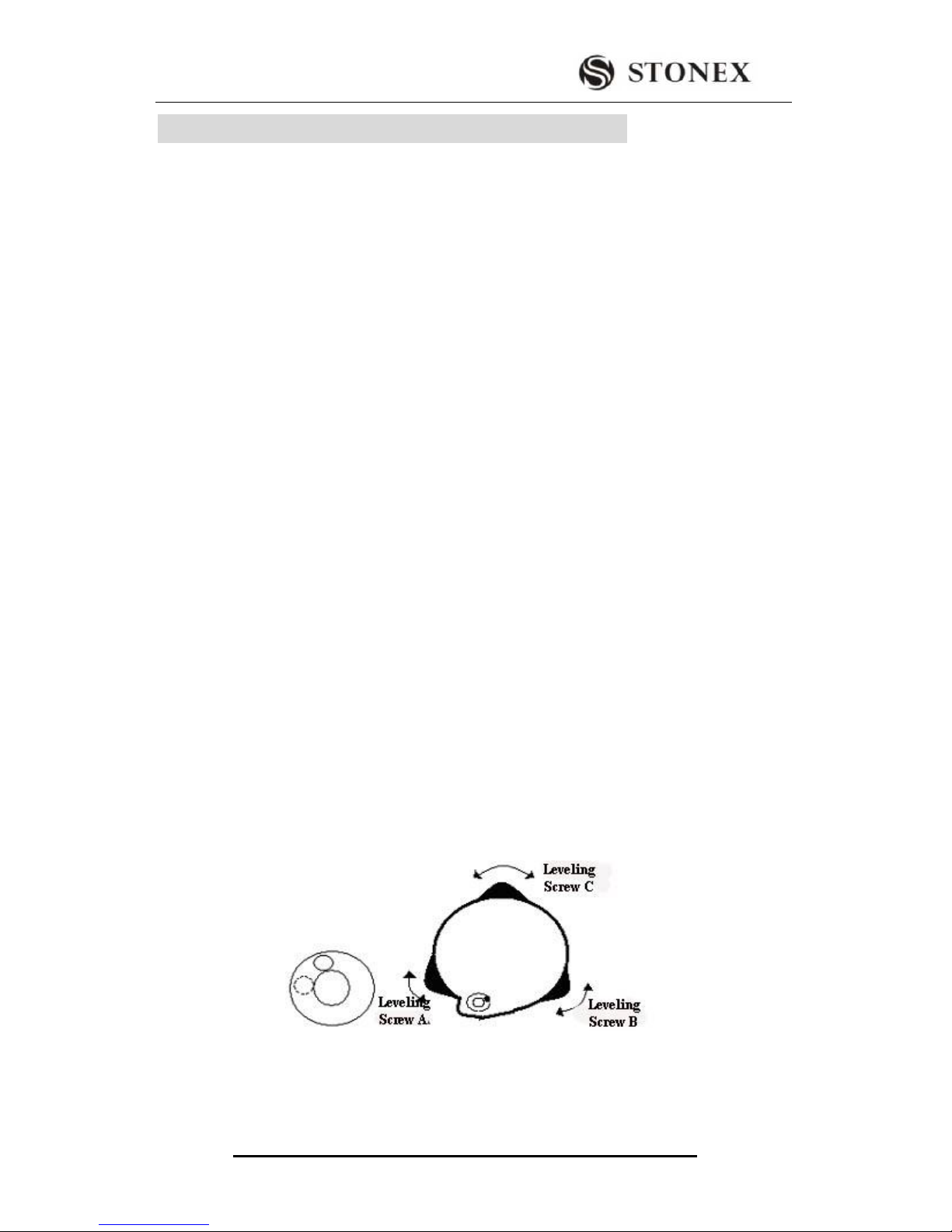
3) Roughly leveling the instrument by using the circular vial
① Turn the leveling screw A and B to move the bubble in the circular vial, in which case
the bubble is located on a line perpendicular to a line running through the centers of the
two leveling screw being adjusted .
Page 16
STONEX R2
12
② Turn the leveling screw C to move the bubble to the center of the circular vial.
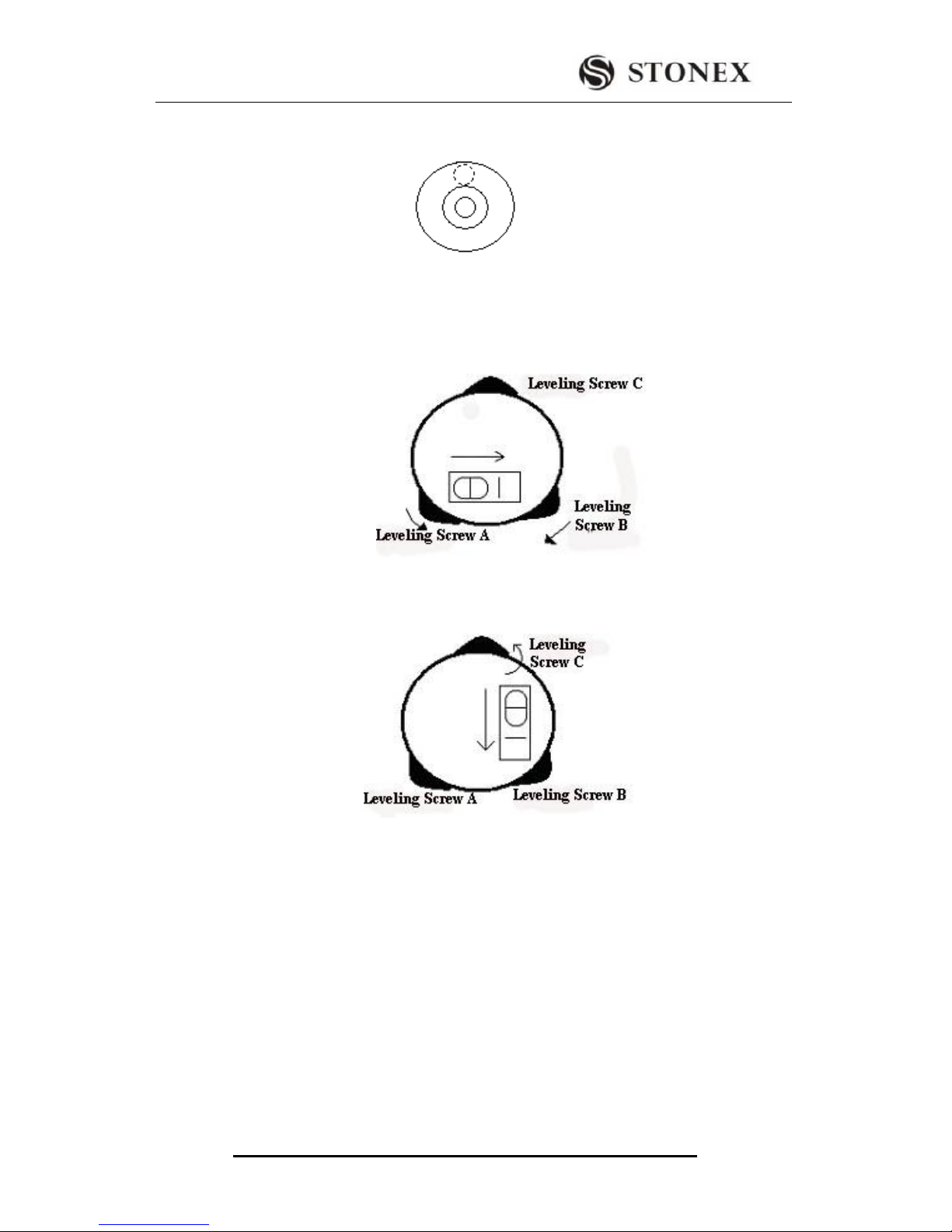
4) Precisely leveling by using the plate vial
① Rotate the instrument horizontally by loosening the Horizontal Clamp Screw and
place the plate vial parallel to the line connecting leveling screw A and B, and then bring
the bubble to the center of the plate vial by turning the leveling screws A and B.
② Rotate the instrument 90º(100g) around its vertical axis and turn the remaining
leveling screw or leveling C to center the bubble once more.
③Repeat the steps ①② for each 90º(100g) rotation of the instrument and check whether
the bubble is correctly centered in all directions.
2 Centering by using the optical plummet
1) Set tripod
Lift tripod to suitable height, ensure equal length of three legs, spread and make tripod
head parallel to the ground, and place it right above the measurement station point. Prop
up tripod on the ground and fix one leg.
2) Install instrument and collimate the point
Set instrument carefully on tripod, tighten the central connecting screw and adjust
Page 17
STONEX R2
13
optical plummet to make the reticle distinctly. Hold the other two unfixed legs with both
hands and adjust position of these two legs through observation of optical plummet. As it
approximately aims at the station point, make all three legs fixed on the ground. Adjust
three leg screws of the instrument to make optical plummet collimate precisely to the
station point.
3) Use circular vial to roughly level the instrument.
Adjust length of three legs of tripod, and make the circular vial bubble of the
instrument in the middle.
4) Use plate vial to level the instrument accurately.
①Rotate the instrument horizontally by loosening the Horizontal Clamp Screw and place
the plate vial parallel to the line connecting leveling screw A and B, and then bring the
bubble to the center of the plate vial by turning the leveling screws A and B.
②Rotate the instrument 90‵, make it perpendicular to the connecting line of level
screws A and B. Turn level screw C to make the bubble of the plate vial in the middle.
5) Precisely centering and leveling
Through observation of optical plummet, slightly loosen the central connecting screw
and move the instrument evenly (Don‟t rotate the instrument), making the instrument
precisely collimating to the station point. Then tighten the central connecting screw and
level the instrument precisely again.
Repeat this operation till the instrument collimate precisely to the measurement
station point.
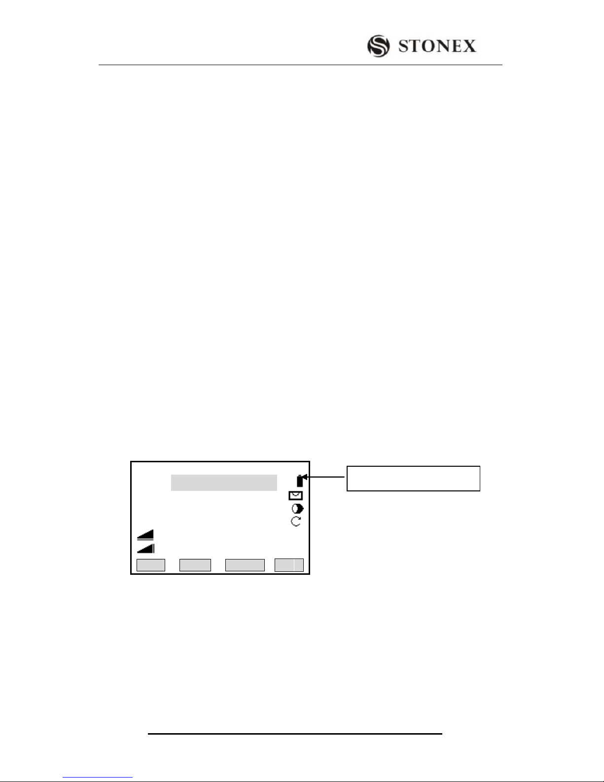
2.3 BATTERY POWER REMAINING DISPLAY
Battery power remaining display indicates the power condition.
Note :
① The battery operating time will vary depending on the environmental conditions such
as ambient temperature, charging time, the number of times of charging and discharging
etc. It is recommended for safety to charge the battery beforehand or to prepare spare full
charged batteries.
② The battery power remaining display shows the power level regarding the current
measurement mode. The distance measurement mode consumes more power than angle
measurement mode, so the power enough for the latter is not sure applicable for the
【 Measure 】 1/4
Pt ID : A1
RHT : 1.500 m
HZ: 0°00′00″
V: 90°00′00″
: ---.--- m Ⅰ
: ---.--- m
ALL DIST RECORD ↓
Power remaining display
Page 18

STONEX R2
14
previous one. Pay particular attention to this when switching angle measurement mode to
distance measurement mode, because insufficient battery power might lead to interrupted
operation.
● Before outdoor operation, battery power status should be well checked.
③ When the measurement mode is changed, the battery power would not immediately
show the decrease or increase. The battery power indicating system shows the general
status but not the instantaneous change of battery power.
² Battery Recharging Cautions:
☆ Battery should be recharged only with the charger SC-21 going with the instrument.
☆ Remove the on-board battery from instrument and connect it to battery charger. When
the indicator lamp on the battery charger is orange, the recharging process has begun.
When charging is complete (indicator lamp turns green), disconnect the charger from
its power source.
²Battery Removal Cautions:
Before removing the battery from the instrument, make sure that the power is turned off.
Otherwise, the instrument may be damaged.
²Battery Recharging Cautions:
☆ The charger has built-in circuitry for protection from overcharging. However,
do not leave the charger plugged into the power outlet after recharging is
completed.
☆ Be sure to recharge the battery at a temperature of 0°~±45°C, recharging may
be abnormal beyond the specified temperature range .
☆ When the indicator lamp does not light after connecting the battery and charger,
either the battery or the charger may be damaged. Please connect professionals
for repairing.
²Battery Charging Cautions:
☆ Rechargeable battery can be repeatedly recharged 300 to 500 times. Complete
discharge of the battery may shorten its service life.
☆ In order to get the maximum service life, be sure to recharge it at least once a
month.
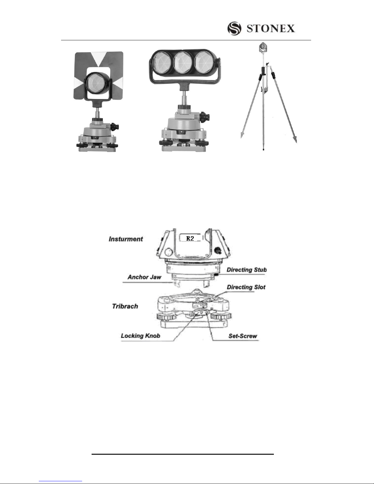
2.4 REFLECTOR PRISMS
When measuring distance, a reflector prism needs to be placed at the target place.
Reflector systems come with single prism and triple prisms, which can be mounted with
tribrach onto a tripod or mounted onto a prism pole. Reflector systems can be
self-configured by users according to job.
Illustrated are some prism systems that match:
Page 19
STONEX R2
15
2.5 MOUNTING AND DISMOUNTING INSTRUMENT FROM TRIBRACH
²Dismounting
If necessary, the instrument (including reflector prisms with the same tribrach) can
be dismounted from tribrach. Loosen the tribrach locking screw in the locking knob with
a screwdriver. Turn the locking knob about 180° counter-clockwise to disengage anchor
jaws, and take off the instrument from tribrach.
²Mounting
Insert three anchor jaws into holes in tribrach and line up the directing stub with the
directing slot. Turn the locking knob about 180°clockwise and tighten the locking screw
with a screwdriver.
2.6 EYEPIECE ADJUSTMENT AND COLLIMATING OBJECT
Method of Collimating Object(for reference)
① Sight the Telescope to bright place and rotate the eyepiece tube to make the reticle
clear.
Page 20

STONEX R2
16
② Collimate the target point with top of the triangle mark in the coarse collimator.
(Keep a certain distance between eye and the coarse collimator).
③ Make the target image clear with the telescope focusing screw.
☆ If there is parallax when your eye moves up, down or left, right, it means the diopter
of eyepiece lens or focus is not well adjusted and accuracy will be influenced, so you
should adjust the eyepiece tube carefully to eliminate the parallax.
2.7 INPUTTING MODE
STONEX R2 Total Station has alphanumeric keypad; Users therefore can input number
and character directly. R2 total station instrument will be introduced particularly as
follows.
²R2:
Each key of R2 Total Station Instrument is defined with three characters and one fig.
Numeric fields:
User can only enter numerical values. By pressing a button of the numeric keypad the
number will be displayed.
Alphanumeric fields:
User can enter numbers and letters. By pressing a button of the alphanumeric keypad the
input opens. By pressing several times you can toggle through the characters. For
example: A->B->C->7„„
If the sign is [AB] at the lower-right corner of screen, you can input number/letter on the
alphanumeric keypad;If it is 01, you can only input numbers. For any requirement for
manually inputting, press [F4] to switch between number and letter inputting mode.
²Sign
The characters which can be input in R2 Total Station Instrument are:A~Z . / $ % _ @ &
* ?! + - etc.
+/-:In number/letter inputting mode, "+" and "-" are treated as normal alphanumeric
characters with no mathematical function. In numeric inputting mode, it can only be used
in front of the input numbers.
²Special characters
* In wildcard searching, it is required to use the sign “*”. In character inputting mode of
R2 instrument, press +/- key once.
In the edit mode, the position of the decimal place can not be changed. The decimal
place is skipped.
Page 21
STONEX R2
17
All keys can be entered into screen.
Use navigation key to move the cursor.
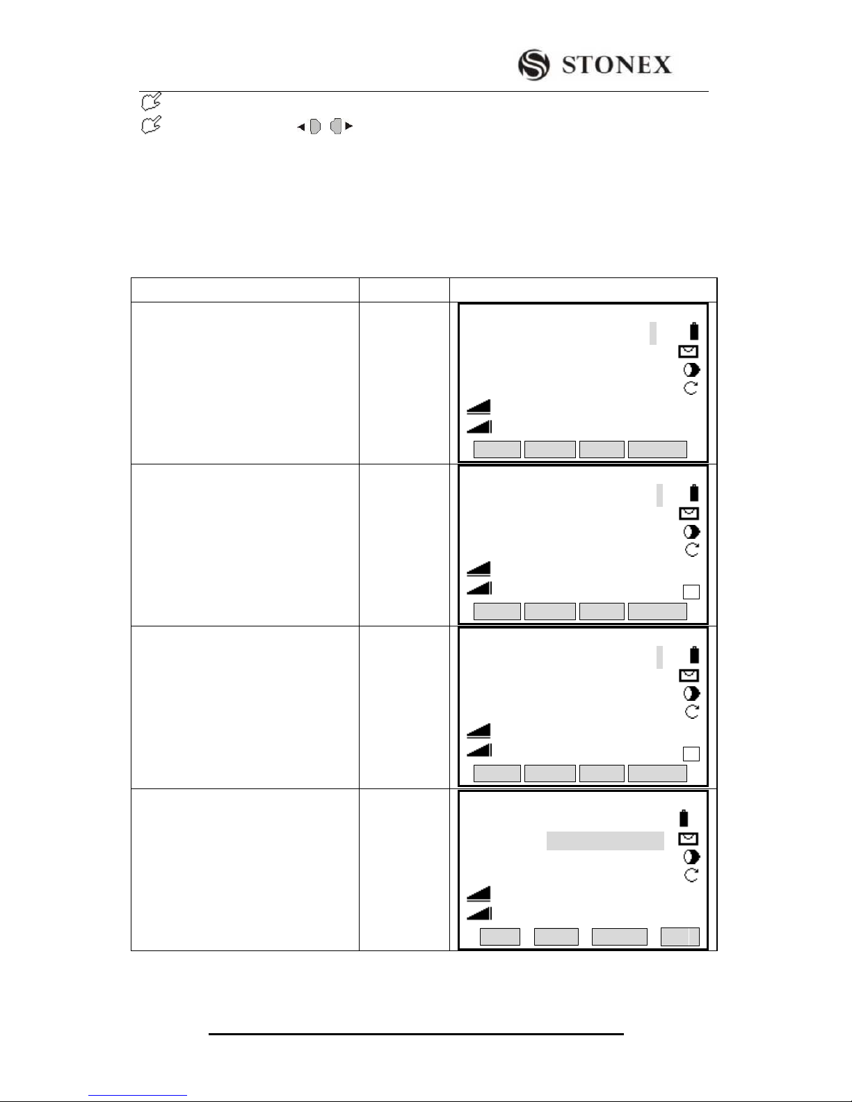
2.7.1 Inputting Character
For STONEX R2: each key is defined with three characters and a figure, as entering the
number/letter inputting mode, every time you press the keypad, a letter would occur at the
cursor, and a number occurs by pressing four times. As the needed character/fig occurs,
the cursor moves automatically to the next item.
E.g.: input 123ABF8
OPERATIONAL STEPS
OPERATION
DISPLAY
①Press the key on numeric keypad to
start inputting. As the sign at the
lower-right corner of the screen is [01],
it is in the numeric inputting mode.
【Measure】 1/4
Pt ID : 1
RHT : 1.500 m
HZ : 0°00′00″
V : 90°00′00″
: ---.--- m Ⅰ
: ---.--- m 01
INSERT DELETE CLEAR NUMBER
② Press numeric key 123, after
inputting figures, press [F4] (ALPH) to
enter character inputting mode.
Input [1]
[2]
[3]
+
[F4]
【Measure】 1/4
Pt ID : 123
RHT : 1.500 m
HZ : 0°00′00″
V: 90°00′00″
: ---.--- m Ⅰ
: ---.--- m AB
INSERT DELETE CLEAR NUMBER
③ Press numeric key “7” once,
showing letter A, the cursor
automatically moves to the next
position, press “7” twice, showing B,
then press “8” three times, showing F,
finally, press “8” four times, to show 8.
So as to finish inputting 123ABF8.
Input [A]
[B]
[F]
[8]
【Measure 】 1/4
Pt ID : 123ABF8
RHT : 1.500 m
HZ : 0°00′00″
V: 90°00′00″
: ---.--- m Ⅰ
: ---.--- m AB
INSERT DELETE CLEAR NUMBER
④Press [ENT] to end inputting and
move to the next item.
[ENT]
【Measure】 1/4
Pt ID : 123ABF8
RHT : 1.500 m
HZ: 0°00′00″
V: 90°00′00″
: ---.--- m Ⅰ
: ---.--- m
ALL DIST RECORD ↓
Page 22
STONEX R2
18
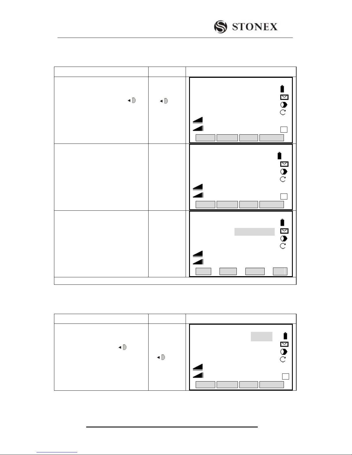
2.7.2 Editing Character
Input characters can be edited.
OPERATIONAL STEPS
OPERATION
DISPLAY
① Press navigation key to
move the cursor to the character
needed to edit.
【Measure】 1/4
Pt ID: STONEX
RHT : 1.500 m
HZ: 0°00′00″
V: 90°00′00″
: ---.--- m Ⅰ
: ---.--- m AB
INSERT DELETE CLEAR NUMBER
②Input new character. (e.g.: input“N”
here)‴1)
Input [N]
【Measure】 1/4
Pt ID: STONEX
RHT: 1.500 m
HZ: 0°00′00″
V: 90°00′00″
: ---.--- m Ⅰ
: ---.--- m AB
INSERT DELETE CLEAR NUMBER
③Press [ENT] to confirm the input.
[ENT]
【Measure】 1/4
Pt ID: STONEX
RHT: 1.500 m
HZ : 0°00′00″
V: 90°00′00″
: ---.--- m Ⅰ
: ---.--- m
Set Hz TILT BEEP ∣←
‴1)About the way to input character, please refer to “2.7.1 inputting character”.
2.7.3 Deleting Character
Input characters can be deleted.
OPERATIONAL STEPS
OPERATION
DISPLAY
① Press navigation key to move
the cursor to the character needed
to delete.
【Measure】 1/4
Pt ID : SSTONEX
RHT : 1.500 m
HZ: 0°00′00″
V: 90°00′00″
: ---.--- m Ⅰ
: ---.--- m AB
INSERT DELETE CLEAR NUMBER
Page 23
STONEX R2
19
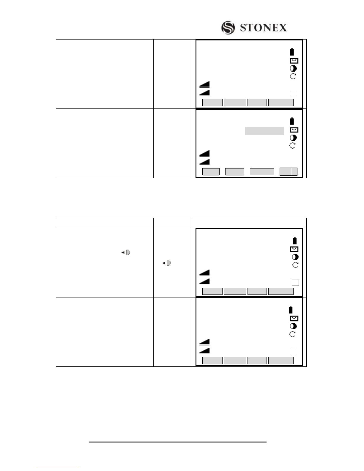
②Press [F2](DELETE).
[F2]
【Measure】 1/4
Pt ID : STONEX
RHT : 1.500 m
HZ: 0°00′00″
V: 90°00′00″
: ---.--- m Ⅰ
: ---.--- m AB
INSERT DELETE CLEAR NUMBER
③Press [ENT] to confirm the input.
To restore the original value, press
[ESC] to cancel the amendment.
[ENT]
Or [ESC]
【Measure】 1/4
Pt ID : STONEX
RHT : 1.500 m
HZ: 0°00′00″
V: 90°00′00″
: ---.--- m Ⅰ
: ---.--- m
ALL DIST RECORD ↓
2.7.4 Inserting Character
If you omit a certain character in inputting, e.g.: “STONEX”has missed out an“N”,
you can insert the character.
OPERATIONAL STEPS
OPERATION
DISPLAY
① Press navigation key moving
the cursor to “O”.
【Measure】 1/4
Pt ID: STONEX
RHT : 1.500 m
HZ: 0°00′00″
V: 90°00′00″
: ---.--- m Ⅰ
: ---.--- m AB
INSERT DELETE CLEAR NUMBER
② Press [F1](INSERT), insert an
empty character on the right of “O” (in
the fig inputting mode, insert “0”)
[F1]
【Measure】 1/4
Pt ID: STOEX
RHT : 1.500 m
HZ: 0°00′00″
V: 90°00′00″
: ---.--- m Ⅰ
: ---.--- m AB
INSERT DELETE CLEAR NUMBER
Page 24
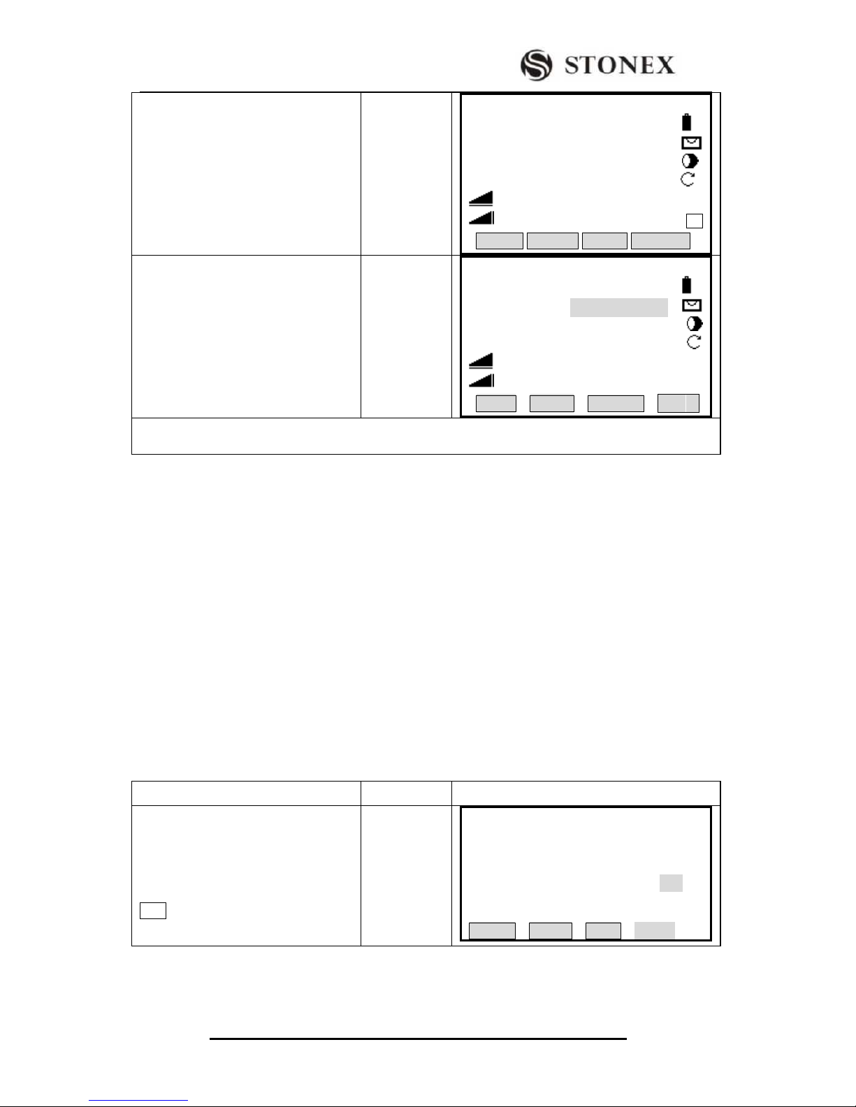
STONEX R2
20
③ The cursor stays at the inserted
empty character, input the omitted
character (here, input “N”). ‴1)
Input [N]
【Measure】 1/4
Pt ID: STONEX
RHT : 1.500 m
HZ: 0°00′00″
V: 90°00′00″
: ---.--- m Ⅰ
: ---.--- m AB
INSERT DELETE CLEAR NUMBER
④Press [ENT] to confirm the input.
To restore the original value, press
[ESC] to cancel the amendment.
[ENT]
Or [ESC]
【Measure】 1/4
Pt ID : STONEX
RHT : 1.500 m
HZ: 0°00′00″
V : 90°00′00″
: ---.--- m Ⅰ
: ---.--- m
ALL DIST RECORD ↓
‴1) To press [INSERT] at the last character, a space will be inserted (In the fig inputting mode, input 0),
and the cursor will move automatically backward (the number of character not exceed the max value.)
2.8 POINT SEARCH
Pointsearch is a comprehensive function, which use a procedure to search measurement
points or known points in internal memory.
The searching scope can be limited to a particular job or the whole storage.
The search procedure always finds known points before measured points that fulfill the
same search criteria. If several points meet the search criteria, then the points are listed
according to their storing time. The instrument finds the most current (youngest) known
point first.
Direct Search
By entering an actual pointID (e.g.: “A12”), all points with the corresponding point
number are found.
There are many places to start the point searching function. Here, take searching the
known points in “setting station” as an example.
OPERATIONAL STEPS
OPERATION
DISPLAY
①In Program, press Surveying, and
after entering measure function, press
Setting Station. Input pointID (Here,
take “A12” as an example) and press
ENT. Then press [F1] (FIND) to start
the FIND function.
Input pointID
+
[F1]
【 Set.Stn 】
Input Station PtID :
StnPt: A12
FIND LIST ENH
Page 25
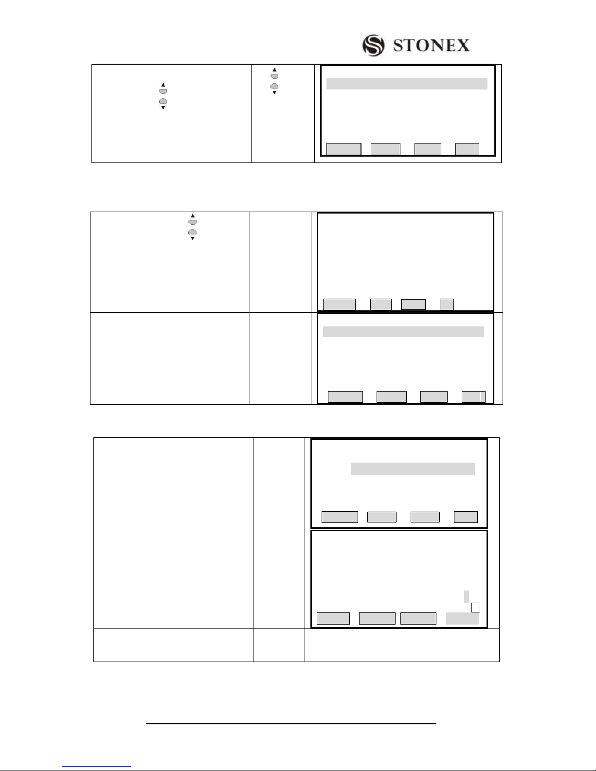
STONEX R2
21
② Display searching result. Use
navigation key to select the point,
after the point you need is found, press
[F4] (OK) or [ENT] to return to last
menu.
+
[F4]
Or[ENT]
【Pt Searching 】 1/25
A12 Known
A12 Meas
A12 Meas
A12 Meas
A12 Meas
A12 Meas
VIEW ENH JOB OK
Introduction of soft keypad at the bottom of the screen:
[VIEW] Display the coordinates of the selected point.
③Use navigation key to select a
pointID, press [F1](VIEW) to display
the coordinate information of this
point.
[F1]
【Pt Search Coord VIEW】
Pt ID: A12
X/N : 100.000 m
Y/E : 100.000 m
H/Z : 26.000 m
DATE: 2006.08.21
TIME: 08:20:56
Start Last OK
④Press [ESC] or [F4](OK) to return to
last menu.
[ESC]
Or
[F4]
【Pt Searching】 1/25
A12 Known
A12 Meas
A12 Meas
A12 Meas
A12 Meas
A12 Meas
VIEW ENH JOB OK
[ENH] Inputs coordinate point manually
③If the pointID you need does not
exist in the job, press [F2] (ENH) to
input coordinate.
[F2]
Coordinate Input
JOB: A:\stonex.Pts
Pt ID: ---.---
X/N : ---.--- m
Y/E : ---.--- m
H/Z : ---.--- m
BACK SAVE
④Input pointID and E,N,Z coordinate.
As one item has been input, press
[ENT] to move the cursor to the next
item.
Input Pt
ID 、ENH
+
[ENT]
Coordinate Input
JOB : STONEX
Pt ID: 10
X/N : 10.000m
Y/E : 100.200 m
H/Z : 10.220 m
01
INSERT DELETE CLEAR
⑤As finishing all inputting, press [F4]
to save the pointID into job.
[F4]
[OK] Confirm the selected point
Page 26
STONEX R2
22
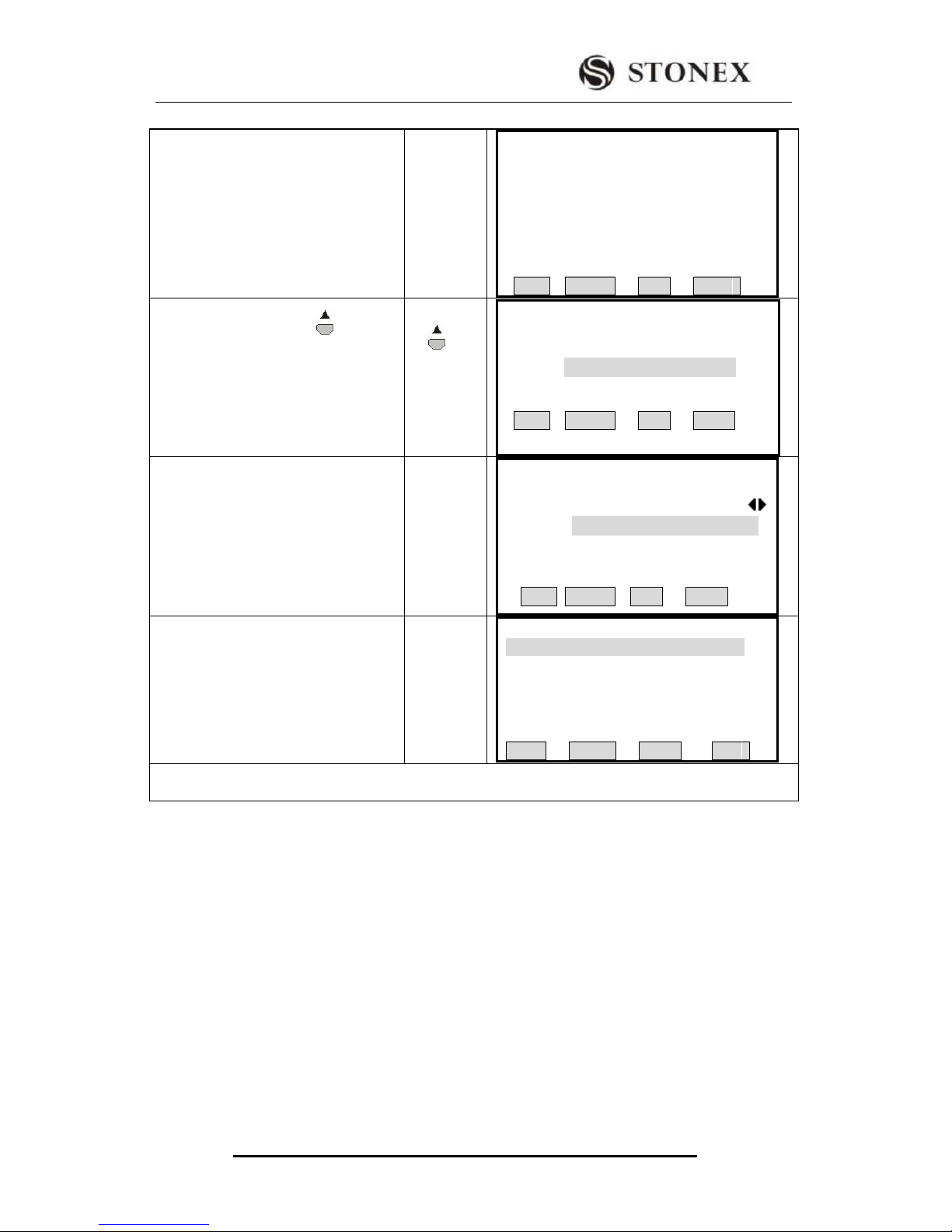
[JOB] Select the pointID in another different job
③If not find the pointID you need in
present job, you can choose it in
another job or input coordinate by
hand in the selected job. Press [F3]
(JOB) key to enter this function.
[F3]
【Pt Search】
JOB : ANDG
Pt ID: *
More Job
Select job/input Pt coord
FIND 0SET ENH LIST
④Press navigation key to move
cursor to job item, select the other jobs
in internal memory, and press [ENT] to
move cursor to the next item.
+
[ENT]
【Pt Search 】
JOB : STONEX
Pt ID: *
More Job
Select job/input Pt coord
FIND 0SET ENH .
⑤Input the pointID to be searched,
then press [ENT]. To input the
coordinate manually, press [0SET] or
[ENH]. ‴1)
Input
pointID
+
[ENT]
【Pt Search】
JOB: STONEX
Pt ID : *
Select job/input Pt coord!
FIND 0SET ENH .
⑥ Press [F1] to search the pointID
meeting the searching conditions in the
selected job.
[F1]
【Pt Search】 1/1
12 Known
VIEW EHN JOB OK
‴1)[F2](0SET ): Press this key to set E, N, Z coordinate of the input pointID as 0 value.
[F3](ENH): Input coordinates of this point manually.
2.9 WILDCARD SEARCH
Use wildcard “*” representing those characters you are going to search.
Wildcards are always used if the pointID is not fully known, or if batches of points are to
be searched for.
Examples:
* All points of any length are found.
A All points with exactly the pointID “A” are found.
A* All points of any length starting with “A” are found (e.g.:A8,A71,ABDE)
*1 All points of any length with a “1” as the second character are found (e.g.:W1,F15,
A1R)
Page 27
STONEX R2
23
A*1 All points of any length with an “A” as the first character and a “1” as the third
character are found. (e.g.:AD1, AR100, AS16)
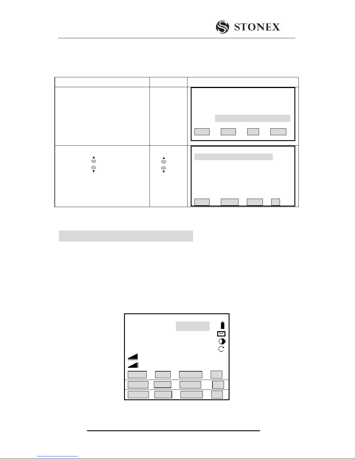
OPERATIONAL STEPS:(taking “*” as an example)
OPERATIONAL STEPS
OPERATION
DISPLAY
①In Program, press Surveying, after
entering measure function, press
Setting Station. Input wildcard “*”:
(Here takes “*”as an example), and
press [ENT]. Then press [F1]
(SEARCH) to start searching function.
Input Pt. ID
+[F1]
【Set.Stn】
Pt. ID :
StnPt : *
VIEW LIST ENH .
② Display search result. Use
navigation key to select pointID you
need, press [F4] (OK) or [ENT] to
return to last menu.
+
[F4]
Or [ENT]
【Pt Search】 1/254
2 Known
A1 Known
12
Known
111 Meas
233 Meas
201 Meas
VIEW ENH JOB OK
3. ROUTINE MEASUREMENT
3.1 DISTANCE SURVEY CAUTIONS
After setting up and switching on correctly, the Total Station is immediately ready for
measuring.In the measurement display it is possible to call up fixed keys, and function
keys, as well as trigger keys and their functions.
All shown displays are examples. It is possible that local software versions are different
from the basic one.
Example of a possible measuring display:
【 Measure 】 1/4
Pt ID :
RHT : 1.500 m
HZ: 0°00′00″
V: 90°00′00″
: ---.--- m Ⅰ
: ---.--- m
All DIST RECORD ↓
SetStn EDM ↓
SET Hz TILT BEEP |←
Page 28

STONEX R2
24
F1-F4 Start the corresponding function
NOTE:
Measurements to strongly reflecting targets such as to traffic lights in infrared mode
should be avoided. The measured distances may be wrong or inaccurate.
When the [MEASURE] (Trigger Key) is triggered, the EDM measures the object
which is in the beam path at that moment.
If e.g. people, cars, animals, swaying branches, etc. cross the laser beam while a
measurement is being taken, a fraction of the laser beam is reflected and may lead to
incorrect distance values.
Avoid interrupting the measuring beam while taking reflectorless measurements or
measurements using reflective foils.
Reflectorless EDM
●Ensure that the laser beams cannot be reflected by any object nearby with high
reflectivity.
●When a distance measurement is triggered, the EDM measures to the object which is in
the beam path at that moment. In case of temporary obstruction (e.g. a passing vehicle,
heavy rain, snow, frog, etc.), the EDM may measure to the obstruction.
●When measuring longer distance, any divergence of the red laser beam from the line of
sight might lead to less accurate measurements. This is because the laser beam might not
be reflected from the point at which the crosshairs are pointing. Therefore, it is
recommended to verify that the R-laser is well collimated with the telescope line of sight.
(Please refer to “10.11 REFLECTORLESS EDM”)
●Do not collimate the same target with the 2 total stations simultaneously.
Accurate measurements to prisms should be made with the standard program (infrared
mode).
Red Laser Distance Measurement Cooperated with Reflective Foils.
The visible red laser beam can also be used to measure to reflective foils. To guarantee the
accuracy the red laser beam must be perpendicular to the reflector foil and it must be well
adjusted (refer to “10.11 REFLECTORLESS EDM”).
Make sure the additive constant belongs to the selected target (reflector).
3.2 EDM SETTINGS
3.2.1 Setting EDM Mode
Choose distance measurement modes, the measurement modes provided by the
instrument are: fine single /fine 2 times /fine 3 times/ fine 4 times/fine 5 times /fine
repeat/tracking.
Page 29
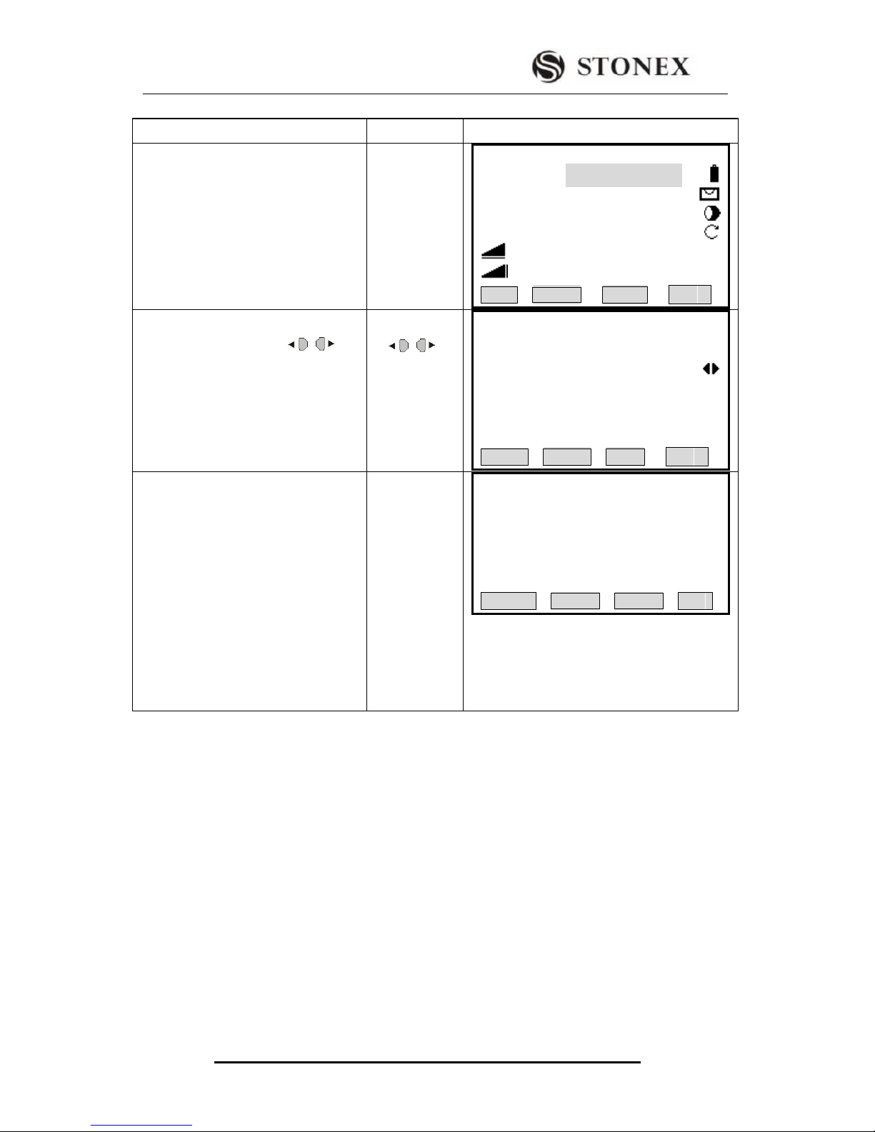
STONEX R2
25
OPERATIONAL STEPS
OPERATION
DISPLAY
① Press [F4]( ↓ ) to display the
second page soft key of surveying.
Press [F3] to enter EDM Settings.
[F4]
[F4]
[F3]
【Measure】1/4
Pt ID :
RHT: 1.500 m
HZ: 0°00′00″
V: 90°00′00″
: ---.--- m Ⅰ
: ---.--- m
SetStn EDM ↓
② As the cursor stays at EDM Mode,
press navigation key to
choose the survey mode.
【EDM Settings】
EDM Mode: Tracking
Prism: 30.0mm
ATMOS GRID SET ↓
③ As finishing setting, Press [F3]
(SET) to return to measure
function.
To cancel the settings, by pressing
[ESC], a dialog will show as the right
picture.
Press [F1] to return to EDM Settings
function to reset EDM parameters.
Press [F4] to quit and return to
measure function.
[F3]
【EDM Settings】
Quit the parameter?
CANCEL OK
3.2.2 Setting Distance Measurement Type
STONEX R2 Total Stations can set options of Red Laser (RL) EDM and Invisible
Laser (IL) EDM, as well as reflector with prism, non-prism, and reflective foil. User can
set them according to the requirements of the job. STONEX R2 Total Stations are only
equipped with laser EDM function, which requires that the prism is in accordance with
the prism constant.
For more parameters of various kinds of reflectors, please refer to “11. Specification”
Page 30
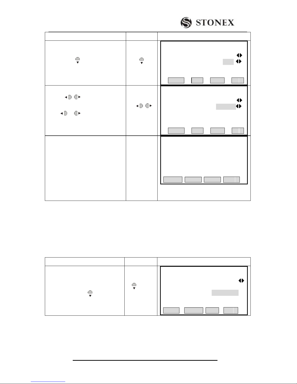
STONEX R2
26
OPERATIONAL STEPS
OPERATION
DISPLAY
① After entering into EDM Setting
screen, press to move to reflector
item.
【EDM Setting】
EDM Mode: Fine [s]
Reflector: Prism
Prism: 30.0mm
ATMOS GRID SET. ↓
②Press to select the reflector
type.
Press or once to change the
type of reflector.
【EDM Setting】
EDM Mode: Fine [s]
Reflector: Non-prism
Prism: 30.0mm
ATMOS GRID SET. ↓
③ After finishing setting, press
[F3](SET) to return to measure
function.
If to cancel the settings, press [ESC], a
dialog will appear as the right picture.
Press [F1] to return to EDM Settings to
renew the EDM parameters. Press [F4]
to return to the measure function.
[F3]
【EDM Settings】
Quit the parameter?
CANCEL OK
3.2.3 Setting the Prism Constant
Since the constants of prisms manufactured by different companies are different, the
corresponding prism constant must be set. Once the prism constant is set, it would be kept
even if the machine is turned off.
● Setting illustration: Prism constant -30mm
OPERATIONAL STEPS
OPERATION
DISPLAY
①After entering EDM Settings screen,
use navigation key to move the
cursor to Prism item.
【EDM Settings】
EDM Mode: Tracking
Prism : 30.0mm
ATMOS GRID SET ↓
Page 31
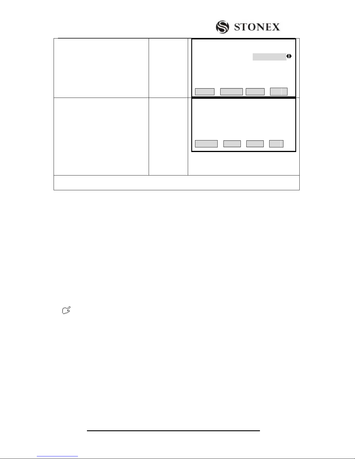
STONEX R2
27
② Input prism constant and press
[ENT].
‴1)~‴2)
Input-30
+
[ENT]
【EDM Settings】
EDM Mode: Tracking
Prism: -30.0mm
ATMOS GRID SET ↓
③ After finishing setting, press
[F3](SET) to return to measure
function.
If to cancel the settings, press [ESC], a
dialog will appear as the right picture.
Press [F1] returning to EDM Settings
to renew the EDM parameters. Press
[F4] to return to the measure function
[F3]
【EDM Settings】
Quit the parameter?
CANCEL OK
‴1) About the way to input prism constant please refer to “2.7 INPUTTING MODE‟
‴2) The scope of prism constant :-99mm~+99mm, Step Length 0.1mm
.
3.2.4 Setting Atmosphere Data
Refraction modules:
The instrument will automatically correct the effect of atmosphere refraction and the earth
curvature when calculating the horizontal distance and the height differences.
The correction for atmosphere refraction and the earth curvature are done by the formulas
as follows:
Corrected Horizontal Distance:
D=S * [cosα + sinα * S * cosα (K-2) / 2Re]
Corrected Height Differentia:
H= S * [sinα + cosα * S * cosα (1-K) / 2Re]
If the correction of atmosphere refraction and the earth curvature is neglected, the
calculation formula of horizontal distance and the height differentia are:
D=S²cosα
H=S²sinα
In formula: K=0.14
……………………
Atmosphere Refraction Modulus
Re=6370 km
………………
The Earth Curvature Radius
α (orβ )
………………...
The Vertical Angle Calculated From Horizontal Plane
(Vertical Angle)
Page 32
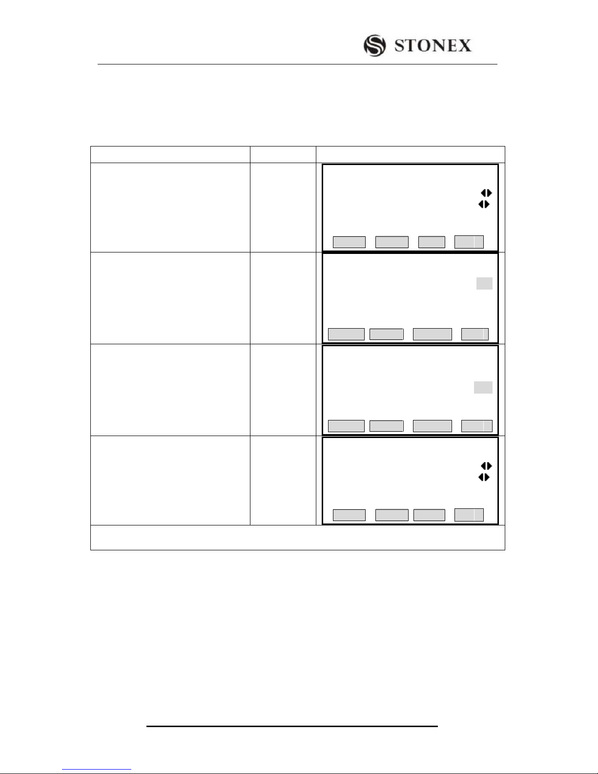
STONEX R2
28
S
………………………….
Oblique Distance
NOTE: The atmosphere refraction modulus of this instrument has been set as: K=0.14. It
also can be set shut: (0 VALUE)
OPERATIONAL STEPS
OPERATION
DISPLAY
①In EDM Settings screen, press [F1]
(Atmos) to enter atmospheric
correction function.
[F1]
【EDM Settings】
EDM Mode: Tracking
Reflect: Prism
Prism: 30.0mm
ATMOS GRID SET ↓
②The current settings displays on the
screen.
【Atmosphere Data】
Retr..Corr: 0.14
Temp: 20‵
Pressure: 1013.2 hPa
Atmos PPM: 0 PPM
BACK PPM=0 SET
③Input refraction modulus. E.g.: input
0.2, and press [ENT], moving the
cursor to Temp item. ‴1),‴2)
Input 0.20
+
[ENT]
【Atmosphere Data】
RetrCorr: 0.20
Temp : 20‵
Pressure : 1013.2 hPa
Atmos PPM: 0 PPM
BACK PPM=0 SET
④As the settings are finished, press
[F4] to store and return to the previous
menu, here you have to press
[F3](SET) to save settings and return
to measure function.
[F4]
[F3]
【EDM Settings】
EDM Mode: Tracking
Reflect: Prism
Prism: -30.0mm
ATMOS GRID SET ↓
‴1)The inputting scope of refraction modulus: 0.00(SHUT) ~0.20
‴2) please refer to “2.7 INPUTING MODE” for inputting instruction.
Atmospheric Parameters (ppm):
Distance measurement is influenced directly by the atmospheric conditions of the air in
which distance measurement are taken.
In order to take into consideration these influences distance measurements are corrected
by using atmospheric correction parameters.
Temperature: Air temperature at instrument location.
Pressure: Air pressure at instrument location.
Atmos PPM: Calculated and indicated atmospheric PPM.
Page 33
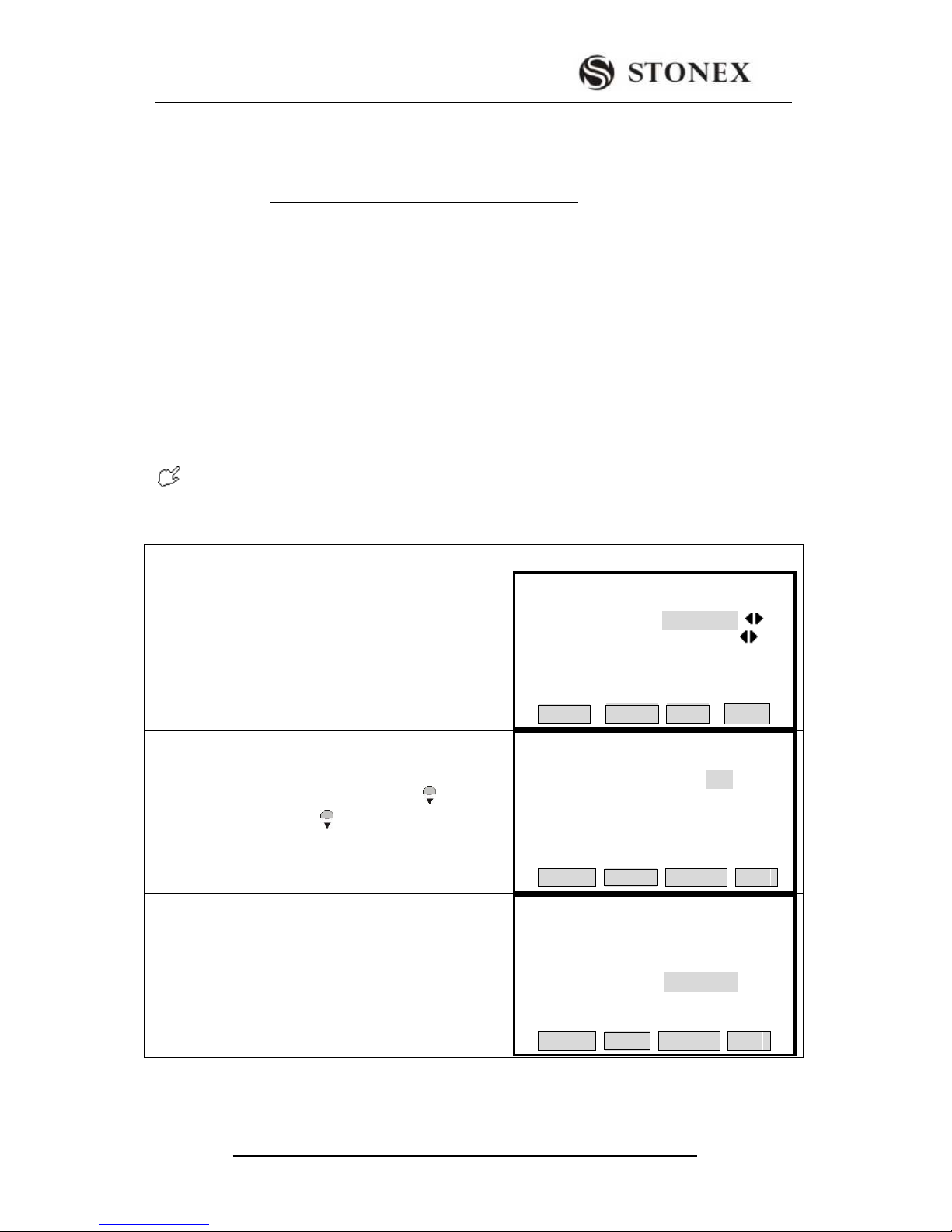
STONEX R2
29
●The calculating formula for atmospheric correction is as follows: (calculating
unit:meter)
PPM = 273.8 - 0.2900 ³ Pressure Value(hPa)
1 + 0.00366 × Temperature value(‵)
If the pressure unit adopted is mmHg: make conversion with:
1hPa = 0.75mmHg.
●The standard atmospheric condition of R SERIES Total Station instrument (e.g. the
atmospheric condition under which the atmospheric correction value of the instrument is
zero):
Pressure:1013 hPa
Temperature: 20‵
If regardless of atmospheric correction, please set PPM value as 0.
OPERATIONAL STEPS
DISPLAY
①In the screen of EDM setting, press
[F1] (Atmos) to enter atmospheric
correction function.
【EDM Settings 】
EDM Mode: Tracking
Reflect: Prism
Prism: 30.0mm
ATMOS GRID SET ↓
②The current settings display on the
screen, use navigation key to move
the cursor to Temp item.
【Atmosphere Data】
Retr.Corr : 0.14
Temp : 20‵
Pressure : 1013.2 hPa
Atmos PPM: 0 PPM
BACK PPM=0 SET
③Input temperature value,
e.g.: Input 26‵, press [ENT] to move
the cursor to Pressure item.
Input 26
+
[ENT]
【Atmosphere Data】
Retr.Corr: 0.14ATUR
Temp: 26‵
Pressure: 1013.2 hPa
Atmos PPM: 0 PPM
BACK PPM=0 SET
Page 34
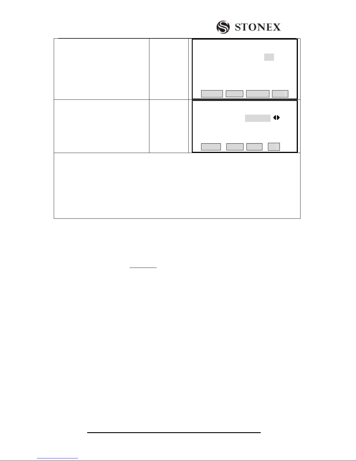
STONEX R2
30
④Input pressure
e.g.: input 1020 hPa, and press [ENT],
the atmospheric correction value will
be calculated by the procedure, the
cursor will move to the refraction
modulus. ‴1),‴2),‴3),‴4)
Input 1020
+
[ENT]
【Atmosphere Data】
Retr.Corr: 0.14
Temp: 26‵
Pressure: 1020.0 hPa
Atmos PPM: 3 PPM
BACK PPM=0 SET
⑤After finishing setting, press [F4] to
save and return to the previous menu,
here press [F3] (SET) again to save the
setting and return to measure function.
[F4]
[F3]
【EDM Settings】
EDM Mode: Tracking
Prism: -30.0mm
ATMOS GRID SET ↓
‴1The inputting scope:Temperature:-40~+60‵(step length 0.1‵) or -40~140℉(step length 0.1℉)
Air pressure:420 ~ 799.5 ㎜ Hg(step length 0.1 ㎜ Hg) or 560 ~ 1066 hPa(step length 0.1hpa)
16.5 ~ 31.5 inchHg(step length 0.1 inchHg)
‴2)Please refer to “2.7INPUTTING MODE” for inputting instruction.
‴3)The atmosphere correction value will be calculated by the instrument according to the inputted
temperature and pressure value.
‴4)Press [F3](PPM=0) to set Atmos correction as zero.
3.2.5 Grid Factor
In coordinate calculation, use horizontal distance to multiply scale factor.
Calculation Formula
1. HEIGHT FACTOR=
ELEVR
R
R : The average radius of the earth
ELEV:The height of the mean sea level
2. SCALE FACTOR
Scale factor: the scale on the measurement station
GRID FACTOR
Grid factor = height factor³scale factor
Distance Calculation
1. GRID DISTANCE
HDg = HD ³ Grid factor
HDg:Grid distance
HD :Ground distance
2. GROUND DISTANCE
Page 35
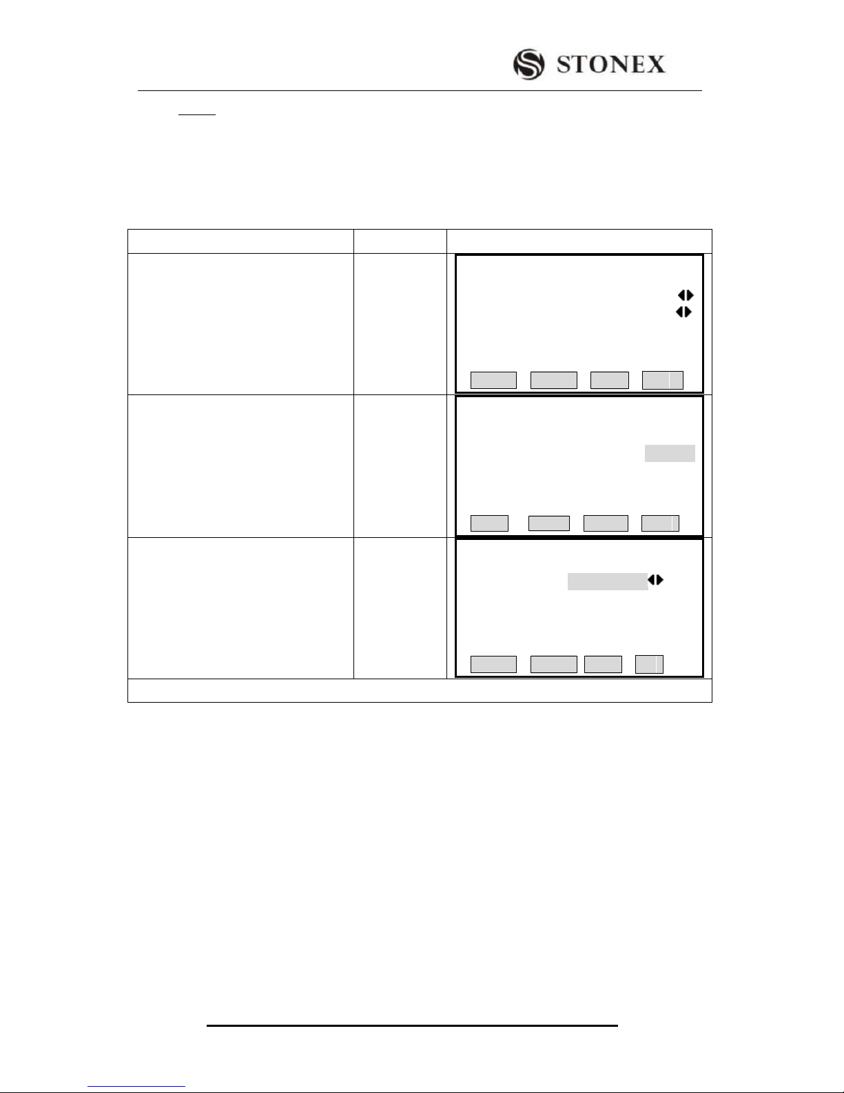
STONEX R2
31
HD =
Grid
HDg
Note: 1.Inputting range of scale:0.990000 ~ 1.010000. The default value: 1.00000
2.Inputting range of average altitude:-9999.8 ~ 9999.8
The average altitude value is rounded off to the nearest tenth and the default value is
zero
OPERATIONAL STEPS
OPERATION
DISPLAY
①On the screen of EDM setting , press
[F2](GRID) to enter Grid Factor
setting.
【EDM Settings】
EDM Mode: Tracking
Reflect: Prism
Prism: 30.0mm
ATMOS GRID SET ↓
②The current settings display on the
screen, input Scale and Ht.a.MSL and
press [ENT]. The procedure will
calculate and display grid. To set All
settings to 0 value, press [F3] (0SET).
‴1)
Input Scale
+
[ENT]
Input
Ht.a.MSL
+
[ENT]
【Grid Factor】
Scale : 1.000000
Ht.a.MSL: 0.0 m
Grid: 1.000000
BACK 0SET SET
③Press [F4](SET) to save the settings
and return to the previous menu, then
press [F3](SET) again to save the
settings being done, and return to
measure function.
[F4]
[F3]
【EDM Settings】
EDM Mode: Tracking
Prism: 30.0mm
ATMOS GRID SET ↓
‴1) Please refer to “2.7 inputting mode” for inputting instruction.
3.2.6 Viewing Signal of Distance Measurement
This function displays the intensity of returned-ray signal (signal intensity) being received
by the total station instrument, step length 1%. Once refraction ray from the prism is
received, this instrument will make beep sound and show the ray intensity which is
expressed by %. The best collimation precision can be realized by this function when the
target is difficult to find or see.
Page 36
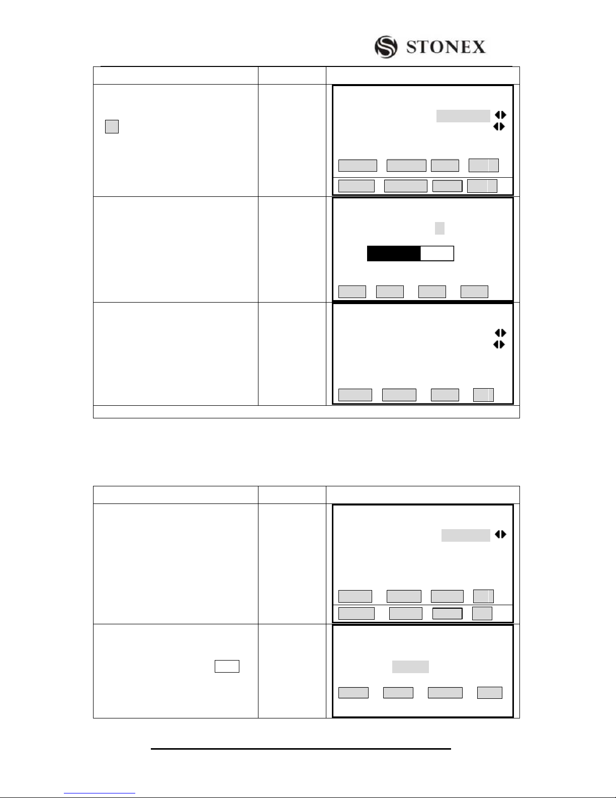
STONEX R2
32
OPERATIONAL STEPS
OPERATION
DISPLAY
①In EDM setting screen, press [F4]
( ↓ ) to display the second page
menu, press [F1] to check the signal of
distance measurement.
[F4]
[F1]
【EDM Settings】
EDM Mode: Tracking
Reflect: Prism
Prism: 30.0mm
ATMOS GRID SET ↓
SIGNAL MulCon ∣←
②The ray intensity which is received
by the machine is expressed by the
bar graph and a % displaying on the
screen, showed as the right picture. ‴
1)
【EDM SIGNAL】
EDM Type: IR
65%
BACK . . .
③Press [F1] to return to EDM setting
menu.
[F1]
【EDM Settings】
EDM Mode: Tracking
Reflect: Prism
Prism: 30.0mm
ATMOS GRID SET ↓
‴1)IR: infrared distance measurement(distance surveyed by the prism)
3.2.7 Setting Multiplication Constant
This function clewed the setting of multiply constant. The value of multiplication
constant will be obtained by examination
OPERATIONAL STEPS
OPERATION
DISPLAY
① On EDM setting function, press
[F4](↓) to display the second page
menu, and press [F2] to set Mul-Cons .
[F4]
[F2]
【EDM Settings】
EDM Mode: Tracking
Prism: 30.0mm
ATMOS GRID SET ↓
SIGNAL MulCon |←
②Input Mul-Cons and press ENT
Input
Mul-Cons
+
[ENT]
【Multiplication Cons】
Mul-Cons : 0.0 ppm
SAVE
Page 37
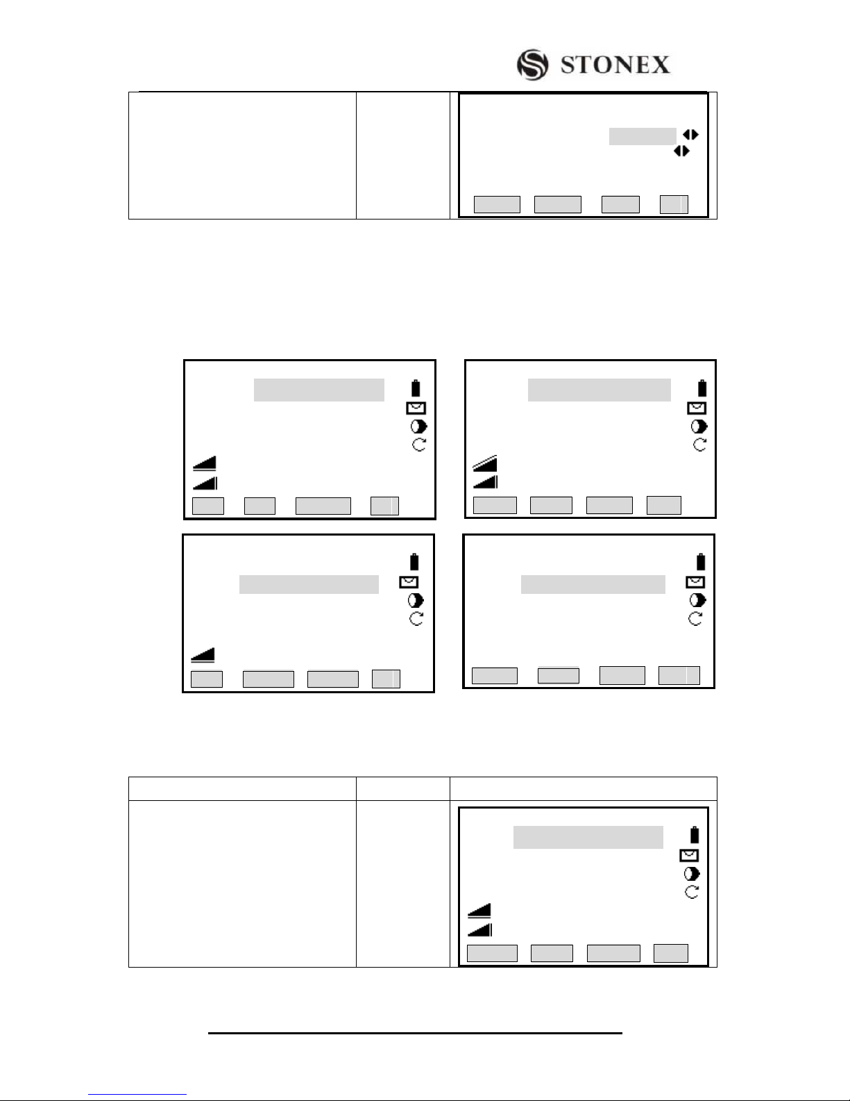
STONEX R2
33
③Press [F4] to save the setting and
return to EDM setting menu.
[F4]
【EDM Settings】
EDM Mode: Tracking
Reflect: Prism
Prism: 30.0mm
ATMOS GRID SET ↓
3.3 START SURVEY
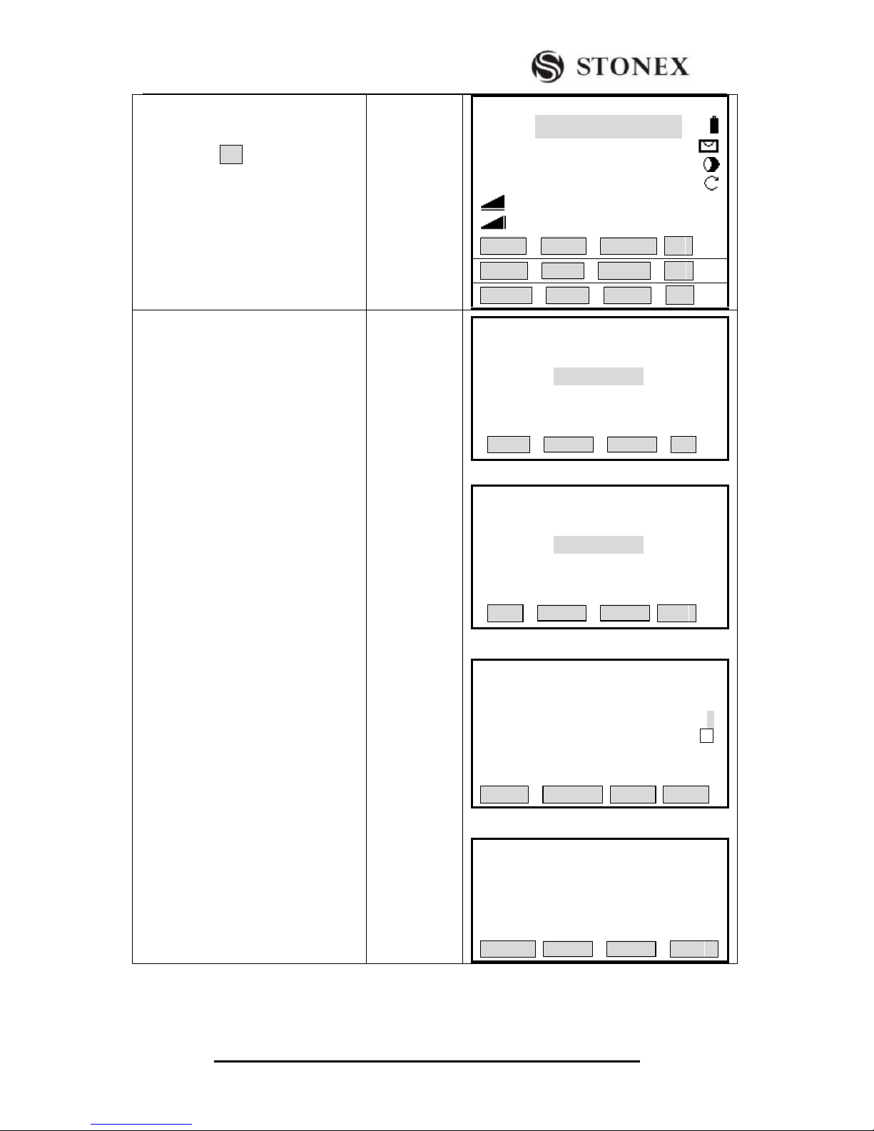
The routine survey is divided into four pages of menu, including all routine measurement
functions, such as angle measurement, distance measurement and coordinate
measurement, which are shown as the pictures below:
3.3.1 Setting Horizontal Circle
OPERATIONAL STEPS
OPERATION
DISPLAY
①Collimate the target point which is
used for orientation setting.
Collimate to
the target
point
【Measure】 1/4
Pt ID: A1
RHT: 1.500 m
HZ : 50°20′00″
V : 82°00′00″
: ---.--- m Ⅰ
: ---.--- m
SET Hz TILT BEEP ∣←
【 Measure 】 2/4
Pt ID : A1
RHT : 1.500 m
HZ: 0°00′00″
V : 90°00′00″
: ---.--- m Ⅰ
: ---.--- m
SET Hz TILT BEEP ∣←
【 Measure 】 1/4
Pt ID : A1
RHT : 1.500 m
HZ: 0°00′00″
V : 90°00′00″
: ---.--- m Ⅰ
: ---.--- m
All DIST RECORD ↓
【 Measure 】 3/4
Pt ID : A1
Code : STONEX
RHT : 1.500 m
HZ : 0°00′00″
V : 90°00′00″ Ⅰ
: ---.--- m
All CODE EDM ↓
【 Measure 】 4/4
Pt ID : A1
R.HT : 1.500 m
HZ : 0°00′00″
X/N : ---.--- m
Y/E : ---.--- m Ⅰ
H / Z: ---.--- m
Set.Stn EDM ↓
Page 38
STONEX R2
34
②Press [F4]( ↓) twice and turn to
the third page of soft key. Press [F1]
(SET Hz) to set horizontal angle.
[F4]
[F4]
[F1]
【Measure】 1/4
Pt ID: A1
RHT: 1.500 m
HZ : 50°20′00″
V : 82°00′00″
: ---.--- m Ⅰ
: ---.--- m
All DIST RECORD ↓
Set Stn EDM ↓
SET Hz TILT BEEP |←
③Screen shows the current horizontal
angle value
A:
To choose the readings of the current
horizontal circle as the orientation
angle, press [F4] (SET) directly.
B:
To choose the other angle value as
orientation angle, just input the needed
angle and press [ENT].
e.g.: input 120°20′30″. ‴1)~‴3)
C:
To set horizontal angle to zero, press
[F1] (0SET). Screen shows as the right
picture and presents whether to set
horizontal angle to zero? If yes, press
[F4] (OK) and return to measure
function. To renew settings, press [F1]
(CANCEL) to return to horizontal
angle setting function.
[F4]
Input HZ
+
[ENT]
[F1]
[F4]
A:press [SET]
B:Input angle
Press[0SET]
【Hz Settings】
HZ: 50°20′00″
0 SET SET
【Hz Settings】
HZ: 50°20′00″
0 SET SET
【Hz Settings】
HZ : 120°20′00″
01
INSERT DELETE CLEAR .
【Hz Settings】
Setting Hz 0?
CANCEL OK
Page 39
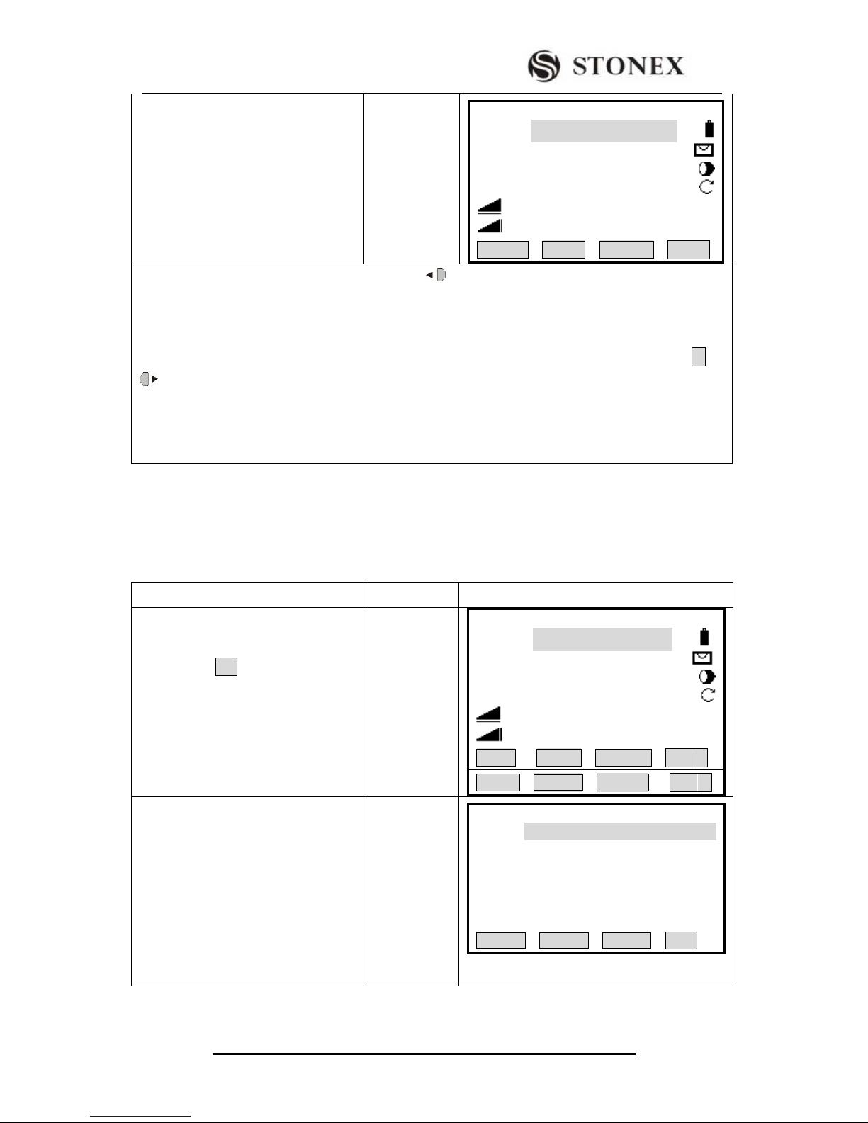
STONEX R2
35
④ Return to measure function, the
horizontal angle set just now is
displayed, here takes setting zero as an
example.
‴4)~‴5)
【Measure】 1/4
Pt ID : A1
RHT : 1.500 m
HZ : 0°00′00″
V : 90°00′00″
: ---.--- m Ⅰ
: ---.--- m
SET Hz TILT BEEP ∣←
‴1)If there is something wrong in inputting, press to move the cursor to the place needed to modify,
or press [F3](CLEAR) and input the correct one
‴2) If an error numerical value is inputted (such as: 70′) and screen do not response the inputting, a
reasonable numerical key has to be pressed
‴3)If the angle unit is degree, minute and second, as part of “degree” is finished, you need to press ² or
to move the cursor to the next inputting area.
‴4) The setting of horizontal left angle/right angle, may be finished in [Main Settings]. Refer to “4.4
Main Settings”.
‴5) For vertical angle setting, it can also be finished in [Main Settings]. Refer to “4.4 Main Settings”.
3.3.2 Setting the Instrument Height and Prism Height
After setting the relative coordinate of the occupied point according to origin point, the
instrument automatically converts and displays the prism point Coordinate based on the
origin and occupied point.
OPERATIONAL STEPS
OPERATION
DISPPLAY
①Press [F4]( ↓), turn to the second
page of soft key, press [F1](SetStn) to
set measurement station and
instrument height.
[F4]
[F1]
【Measure】 1/4
Pt ID: A1
RHT: 1.500 m
HZ : 0°00′00″
V : 90°00′00″
: ---.--- m Ⅰ
: ---.--- m
All DIST RECORD ↓
SetStn EDM ↓
②Input the pointID of measurement
station, instrument height and
coordinate. After finishing one item,
press [ENT] to move the cursor to the
next one. Since the Desc. item
describes measurement station, it may
not be inputted
Input
pointID of
measurement
station point
+
[ENT]
Input INS.Ht
+
[ENT]
Input ENH
+
[ENT]
【Set.Stn 】
Pt ID : OCC1
INS.Ht: 1.000 m
Desc: --- --- --- --X0/N0 : 0.000 m
Y0/E0 : 0.000 m
H0 : 0.000 m
SET
Page 40
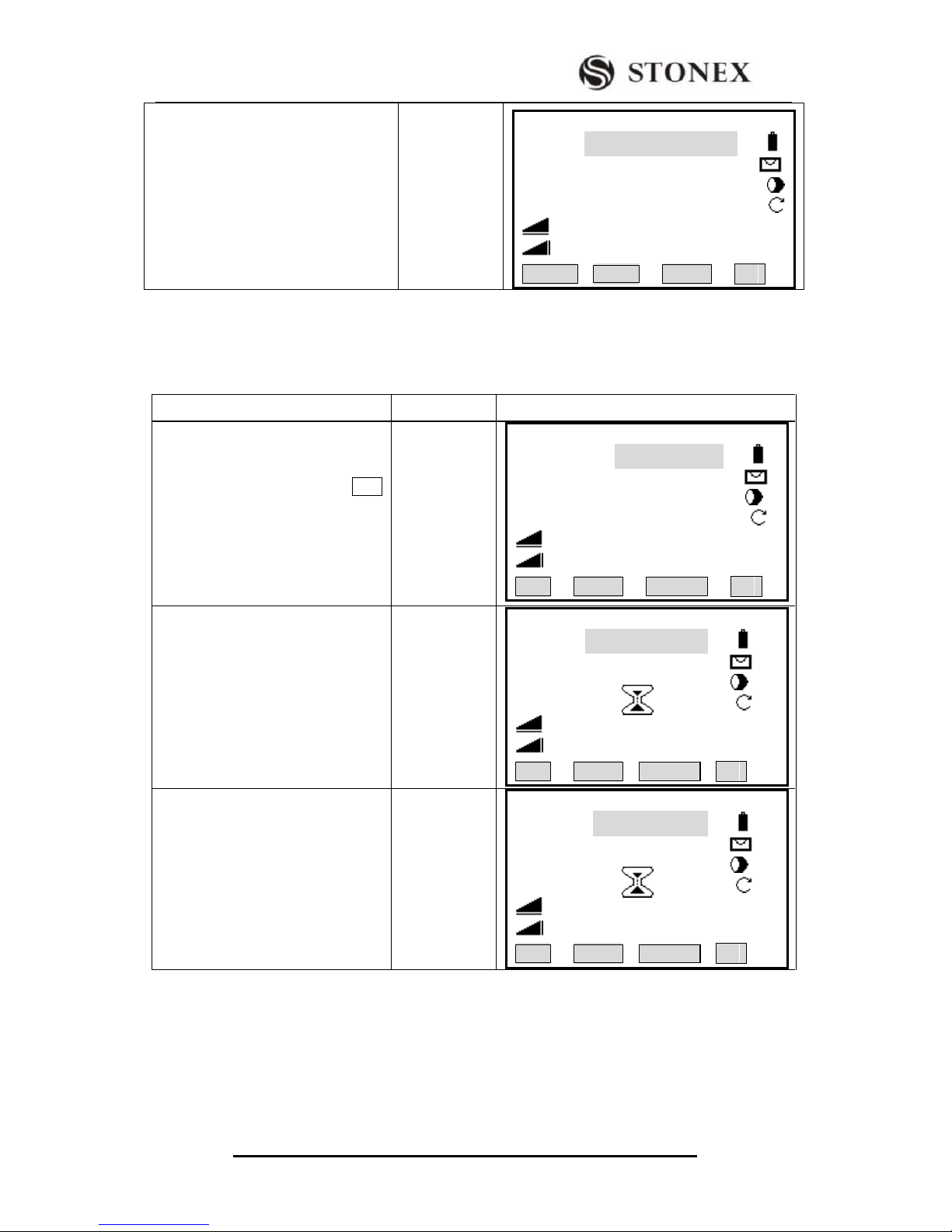
STONEX R2
36
③As all inputting items are finished,
press [F4](SET) to keep the data of
measurement station and return to
measure function.
[F4]
【Measure】 1/4
Pt ID: A1
RHT: 1.500 m
HZ: 00°00′00″
V: 90°00′00″
: ---.--- m Ⅰ
: ---.--- m
SetStn EDM ↓
3.3.3 Measurement
As all settings are finished, you can start survey now, the survey result has four
pages including all general survey data, press [PAGE] to check.
OPERATIONAL STEPS
OPERATION
DISPLAY
①Input pointID and prism height,
after finishing one item, press ENT
to move the cursor to the next item.
Input the coding if necessary.
Input Pt ID
+
[ENT]
Input RHT
+
[ENT]
【Measure】 1/4
Pt ID: A1
RHT: 1.500 m
HZ : 0°00′00″
V : 90°00′00″
: ---.--- m Ⅰ
: ---.--- m
All DIST RECORD ↓
②Collimate the prism center, press
[F1](All) or [F2](DIST) +
[F3](RECORD) to start survey, and
record the data being surveyed. The
measured and recorded data
include angle, distance, coordinate,
press [PAGE] to see
[F1]
or
[F2]
+
[F3]
【Measure】 1/4
Pt ID : A1
RHT: 1.500 m
HZ: 51°20′10″
V: 90°00′00″
: ---.--- m Ⅰ
: ---.--- m
All DIST RECORD ↓
③Once a point of survey is finished,
the pointID will be automatically
added 1 by the procedure, collimate
the prism center to repeat the steps
and start to measure the next point.
‴1).
【 Measure】 1/4
Pt ID: A2
RHT: 1.500 m
HZ : 51°20′10″
V : 90°00′00″
: ---.--- m Ⅰ
: ---.--- m
All DIST RECORD ↓
The other soft keys at the bottom of the screen:
Compensation: To set Open and Shut of tilt compensation, with options of 1-axis and
OFF. Please refer to “4.1 LEVELING” for detailed introduction.
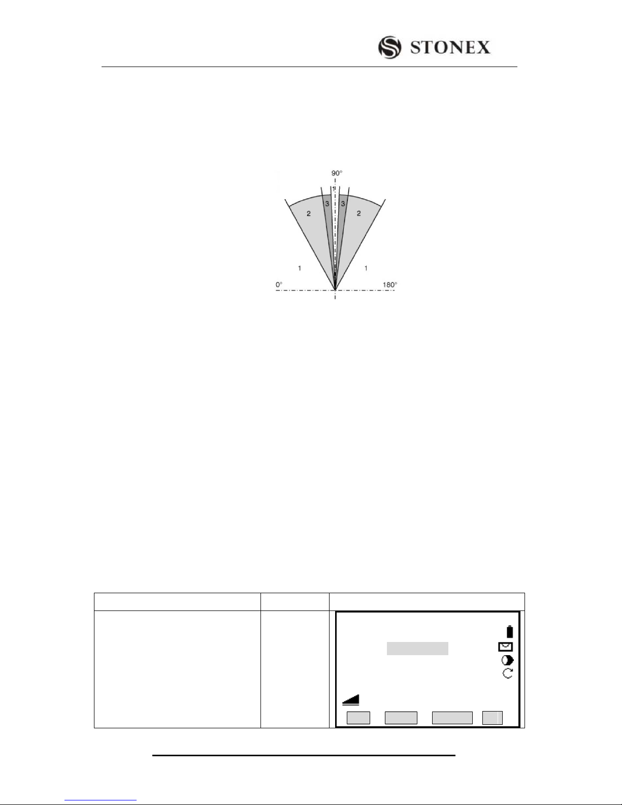
Sector Beep
[F1]ON: Sector Beep sounds at right angles (0º,90º,180º,270º or 0,100,200,300gon)
Page 41
STONEX R2
37
[F2]OFF: Sector Beep switched off.
Sector Beep Example: From 95.0 to 99.5 gon (or from 105.0 to 100.5 gon) a “Fast beep”
sounds. From 99.5 to 99.995 gon (or from 100.5 to 100.005 gon) a “Permanent beep”
sounds.
As shown in the picture below:
IN GRAPH : 1) No beep
2) Fast beep (interrupted).
3) Permanent beep.
3.3.4 Coding
Codes contain information about recorded points. With the help of coding, points can be
assigned to a particular group simplifying later processing. More information on coding
can be found under “File Management”.
The operational steps of simple coding:
1, Move the cursor to the “Code” column
2, Input coding name
3, Press [All] to start distance measure and record the coding and measurement
data together. Press [Code] to search inputted coding and modify the attributes
OPERATIONAL STEPS:
OPERATIONAL STEPS
OPERATION
DISPLAY
①Press [PAGE] to display measure
page of 3/4 and move the cursor to
Code item.
[PAGE]
+
[F4]
【Measure】 3/4
Pt ID: A1
Code: --- --- CODING
RHT: 1.500 m
HZ:: 63°40′50″
V : 94°33′51″ Ⅰ
: ---.--- m
All DIST RECORD ↓
Page 42
STONEX R2
38
②Input the code, and press [F4](↓) to
display the second page soft key, here,
the single coding being input will not
be enlisted in code storeroom.
A: Press [F1] (All) to start
measurement, save all data of the
coding and measurement into job.
‴1)
B: Press [F2] (Code) to search the
codes already inputted.
Input the code
+
[F4]
A:Press[All]
B:Press [Code]
【Measure】 3/4
Pt ID : A1
Code: STONEX
RHT: 1.500 m
HZ: 63°40′50″
V: 94°33′51″ Ⅰ
: ---.--- m
All DIST RECORD ↓
All CODE EDM ↓
【Measure】 3/4
Pt ID : A1
Code : STONEX
RHT: 1.500 m
HZ: 63°40′50″
V: 94°33′51″ Ⅰ
: ---.--- m
All CODE EDM ↓
【Code Search】1/2 ▼
Select / Input new code!
Search: STONEX
Code : --- ---
Desc : --- --Info1 : --- --Info2 : --- --RECORD ADD OK
‴1)The save sequence of the data of coding and measurement is set in „Settings‟ or „Main settings‟
The settings of coding record are: save before, save after. Here explain separately as follows:
save before:to save coding data before practical survey data
save after :to save the coding data closely after practical survey data
Please inquire in “measurements‟ document
After starting [Coding] function, the coding screen shows as follows:
【Code Search】1/2 ▼
Select / Input new code!
Search: --- ---
Code : --- ---
Desc : --- --Info1 : --- --Info2 : --- --RECORD ADD OK
GSI- code:
Page 43
STONEX R2
39
CODE: Code name
DESC: Additional remark
Info1: Editable information including more content
……
Info8 : Lines
After Code Search function is started, if the code name is already in the code
storeroom, it can be edited. Here the edited data can not be kept in the code storeroom any
more. You may press [RECORD] to keep it in data document as a single coding datum, or
press [All] (or [DIST] + [RECORD]) to keep it in data document together with those
survey data as a single coding datum. Besides, the save sequence of coding data and
practical measurement data can also be set (to set in the item Code Record in “Main
Settings” and “Settings”).
To set code „save before‟: represents that as the survey is finished, the coding datum will
be saved before practical survey data.
To set code „save after‟: represents that this coding datum is saved after practical survey
data.
If the code input does not exist, after editing, you may press [ADD] to add a new code
to code storeroom, or press [RECORD] or [All] (or [DIST] + [RECORD]) to keep it as a
single coding datum in survey data document
The operations under two situations are introduced separately:
1)The inputted coding name exists in the store:Extend/edit codes
As the needed code is called up from code list, the attributes can be overwritten freely.
OPERATIONAL STEPS
OPERATION
DISPLAY
①The procedure automatically search
the code in code storeroom, if the
inputted code exists, it will be
displayed in Code item. ‴1)
【Code Search】 1/2▼
Select / Input new code!
Search:
Code: --- ---
Desc: --- --Info1 : --- --Info2 : 1/2 --- --RECORD ADD OK
Page 44
STONEX R2
40
②Expand/edit the coding attributes, as
one item is input, press ENT to move
the cursor to the next item.
Edit the
coding
attributes
+
[ENT]
【Code Search】1/2 ▼
Select / Input new code!
Search: SAN
Code : SAN
Desc : --- --Info1 : --- --Info2 : --- --RECORD ADD OK
③ The edited code can be kept in
measurement document.
A: Press [F1](RECORD) to return to
measure function, set the input code as
the code of the present measuring point
and add a new coding datum to
Measurements document. ‴ 2)
B : Press [F2] (ADD), a dialog
appearing as the right picture. The
same code can not be added repeatedly,
press [F4] to return. ‴3)
C: Press [F4] (OK) only to set the
inputted code as the code of the present
measuring point and return to the
measure function. ‴4)
[F4]
A:press[RECORD]
B:Press[ADD]
【Measure】 3/4
Pt ID: A1
Code:
RHT: 1.500 m
HZ: 0°00′00″
V: 90°00′00″ Ⅰ
: ---.--- m
All CODE EDM ↓
【Code Search】
Code Exist!
OK
‴1) A wildcard“*”can also be input to search all codes in code storeroom, press to display each
code. Press [PAGE] to see the other pages of coding attributes.
‴2)The added coding data can be found in Measurements of File Management.
‴3)The same code name can not be added repeatedly in code storeroom
‴4) Press [OK] to conclude the coding function, the coding blocks are kept in the system temporarily, and
they can only be recorded together with the practical measurement point.
The settings of coding record in “Settings” or “Main settings” are “save before and save after”, here
explain separately as follows:
save before:to save coding data before practical survey data
save after :to save the coding data closely after practical survey data
Please inquire in “measurements‟ document.
2)If the code does not exist in code storeroom, input each item of coding attributes
manually
OPERATIONAL STEPS
OPERATION
DISPLAY
Page 45
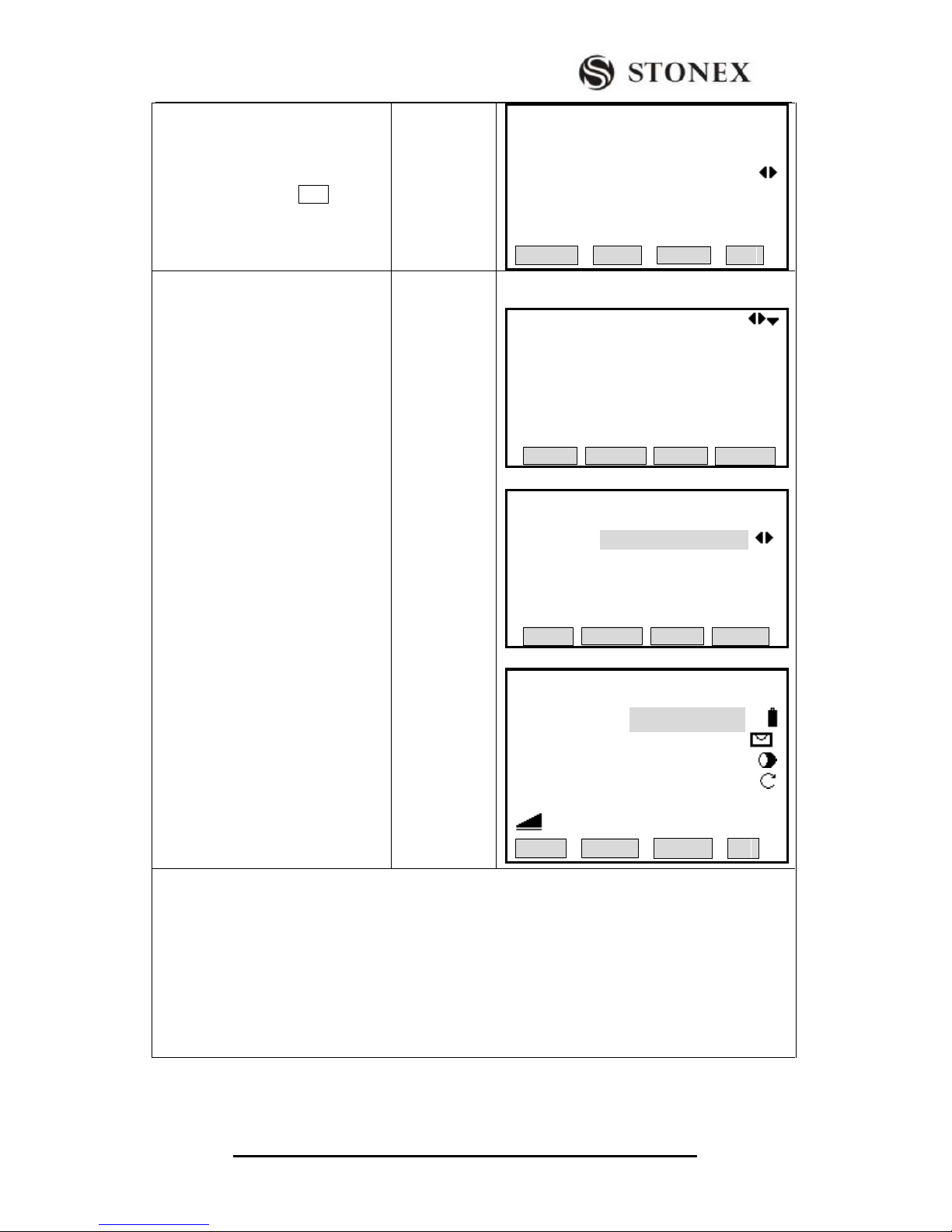
STONEX R2
41
① Individual code blocks can be
entered directly via keypad. Once an
item is finished, press ENT to move
the cursor to the next attribute. ‴1)
Input the
coding
attributes
+
[ENT]
【Code Search】 1/2▼
Select / Input new code!
Search:
Code: --- ---
Desc : --- --Info1 : --- --Info2 : --- ---
RECORD ADD OK
②A:Press [F1](RECORD) to return
to Measure function, and set the
input coding as the code of the
present measuring point, add a new
coding datum to Measurements
document ‴2)
B: Press [F2] (ADD). Besides
returning to measure function and
setting the input code as the code of
present measuring point, a new code
will also be added to the code
storeroom. ‴3)
C: Press [F4] (OK) only to set the
input code as the code of present
measuring pointID and return to
measure function. Only by starting
surveying can the input coding be
saved into Measurements documents
along with measuring operations.
‴4)
A : The code data being added to
Measurements document
B:New code added in the code storeroom:
C:
【VIEW】 88
Mode: CODING SYS.MESS
Pt ID: --- --- ---
Code: STONEX
Desc: --- --- --Date: 05.08.2006
Time: 11:29:41
SEARCH
【Code search / delete】1/2 ▼
Search: *
Code : STONEX
Desc: VIP
Info1 : --- --Info2 : --- --Info3 : --- ---
NEW DELETE
【Measure】 3/4
Pt ID: A1
CODE: STONEX
RHT: 1.500 m
HZ: 63°40′50″
HZ: 94°33′51″ Ⅰ
: ---.--- m
All CODE EDM ↓
‴1)Press [PAGE] to edit /view the other pages of the coding attributes
‴2)The added coding datum can be seen in Measurements of File Management.
‴3)The added coding can be found in the code storeroom.
‴4)Press [OK] to conclude the coding function, the coding blocks are kept in the system temporarily,
and they can only be recorded together with the practical measurement point.
The settings of coding record in “Settings” or “Main settings” are: save before and save after,
here explain separately as follows:
save before:to save coding data before practical survey data
save after :to save the coding data closely after practical survey data
Please inquire in “Measurements” document.
3.3.5 Quick Code
Page 46
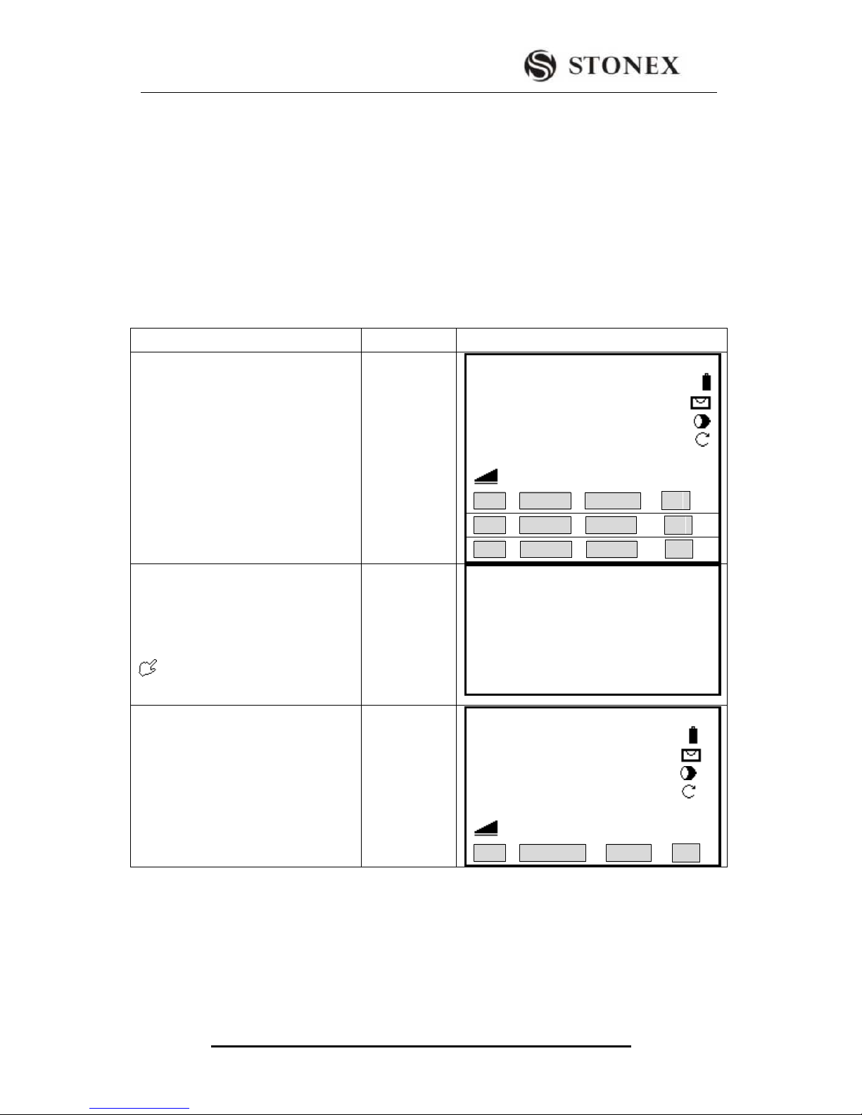
STONEX R2
42
Using the quick code function, a predefined code can be called up directly via numeric
keypad on the instrument. The code is selected by entering a two digit number, the
measurement is triggered and the measured data and code saved.
A total of 100 codes can be assigned; you may create codes with “Codelist Manager”
provided by STONEX Company, and transfer to the instrument. Each code can be
assigned a unique one or two digit number in the “Codelist Manager”.
If no numbers are allocated to the codes in “Codelist Manager”, the code is selected in
accordance with the order in which the codes were entered in the code list (e.g.: 01->: first
code in the code list. 10-> tenth code in the code list). About the coding format please
refer to appendix A.
OPERATIONAL STEPS
OPERATION
DISPLAY
①Collimate the prism center of the
target point, and input pointID and
prism height, press[PAGE] to display
measure page of 3/4,press [F4](↓) to
display the third page soft key
Collimate to
the target
point +
Input PtID,
RHT +
[PAGE]
+ [F4]
【Measure】 3/4
Pt ID: A1
Code : --- --- CODING
RHT: 1.500 m
HZ: 63°40′50″
V: 94°33′51″ Ⅰ
: ---.--- m
All DIST RECORD ↓
All CODE EDM ↓
All Q-CODE EDM |←
②Press [F2](Q-CODE) to start quick
code function. Screen prompts „Q-code
active!‟ and then return to measure
page of 3/4.
Press [F2] again, and shut Q-CODE
function.
[F2]
Q-code active!
③ The serial number of the input
quick coding in internal memory is a 2
digit number. ‴1)
Input the
serial number
of Q-CODE
【Measure】 3/4
Pt ID: A1
Code : --- --- CODING
RHT: 1.500 m
HZ: 63°40′50″
V: 94°33′51″ Ⅰ
: ---.--- m
All Q-CODE EDM ∣←
Page 47
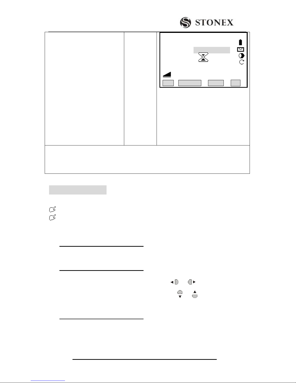
STONEX R2
43
④Procedure starts code searching to
search the quick coding in internal
memory.
If find the quick coding corresponding
to the code, then the survey function
will start, and the survey result and
quick coding will be displayed as this
survey is finished.
If the quick coding corresponding to
the code doesn‟t exist in internal
memory or the code quantity in
internal memory is smaller than the
code, it will display “Code no Exist!”
‴2)
【Measure】 3/4
Pt ID: A1
Code: CODING
RHT: 1.500 m
HZ: 63°40′50″
V:: 94°33′51″ Ⅰ
: 1.963 m
All Q-CODE EDM ∣←
‴1)Even if only 1digit is dispatched to the coding in “code block manager”, 2 digit numeric code should
be inputted. E.g.: 4->Input 04
‴2)If the code is input on the instrument, or the code has not been dispatched a quick code in “code block
manager”, the code will be numbered in its save sequence, therefore, as the input quick code is bigger than
the total number of codes, the program will prompt “Code no Exist!”
4. FUNCTIONS
Several functions can be called up via [FNC] key.
Functions can also be started directly from different applications.
Each function from the FNC menu can be assigned to the [USER] key. (See 4.4
“Main Settings”)
Several functions:
Light ON/OFF
Switches display light on/off.
Units
Display the current distance and angle unit. Pressing or can change the units.
After one setting is finished, move to the next by pressing or . When all settings are
done, press [SET] to save and return.
Free-Coding
Select codes from the code list or enter a new code.
Page 48
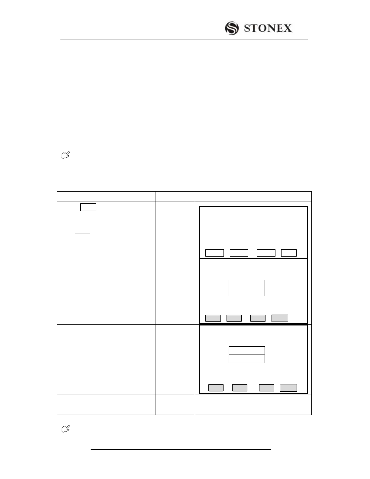
STONEX R2
44
4.1 LEVELING
As the tilt sensor is activated, automatic correction of vertical angle for unlevelment is
displayed.
To ensure a precise angle measurement, tilt sensor must be activated (See 4.4 Main
Settings), and the display can be used to fine level the instrument.
If the instrument hasn‟t been leveled roughly, the screen displays that the instrument is out
of the automatic correction range, and that it needs to be leveled manually. Please refer to
“2.2 Instrument Setup” for detailed leveling instruction.
STONEX R2 Total Station compensates the vertical angle reading due to inclination
of the vertical axis in the X directions.
OPERATION STEPS
OPERATION STEPS
OPERATION
DISPLAY
①Press FUNCto enter into the routine
function Menu, then press F1 (Level),
then enter the Tilt adjust screen. Then
press PAGE to find the value, if the
value is within ±3′, it indicates that it
is with the designed range of automatic
tilt correction. Press [F4] to return to
Measure menu.
If the value exceeds ±3′ , manual
leveling is a must.
[F1]
【Tilt Adjust】
F1 Level
F2 Target Offset
F3 Delete Last Record
F4 Main setting
F1 F2 F3 F4
【Tilt Adjust】
X:-0°10′21″
Y:-0°07′08″
BACK
②If the instrument hasn‟t been leveled
precisely, rotate the tribrach screws
and level the instrument according to
the value‟s changing displayed in the
screen.
【Tilt Adjust】
X:-0°00′21″
Y:-0°00′08″
BACK
③After leveling, press [F4] to return
to Measure menu.
When the instrument is placed on an unstable stage or in a windy weather condition,
Page 49
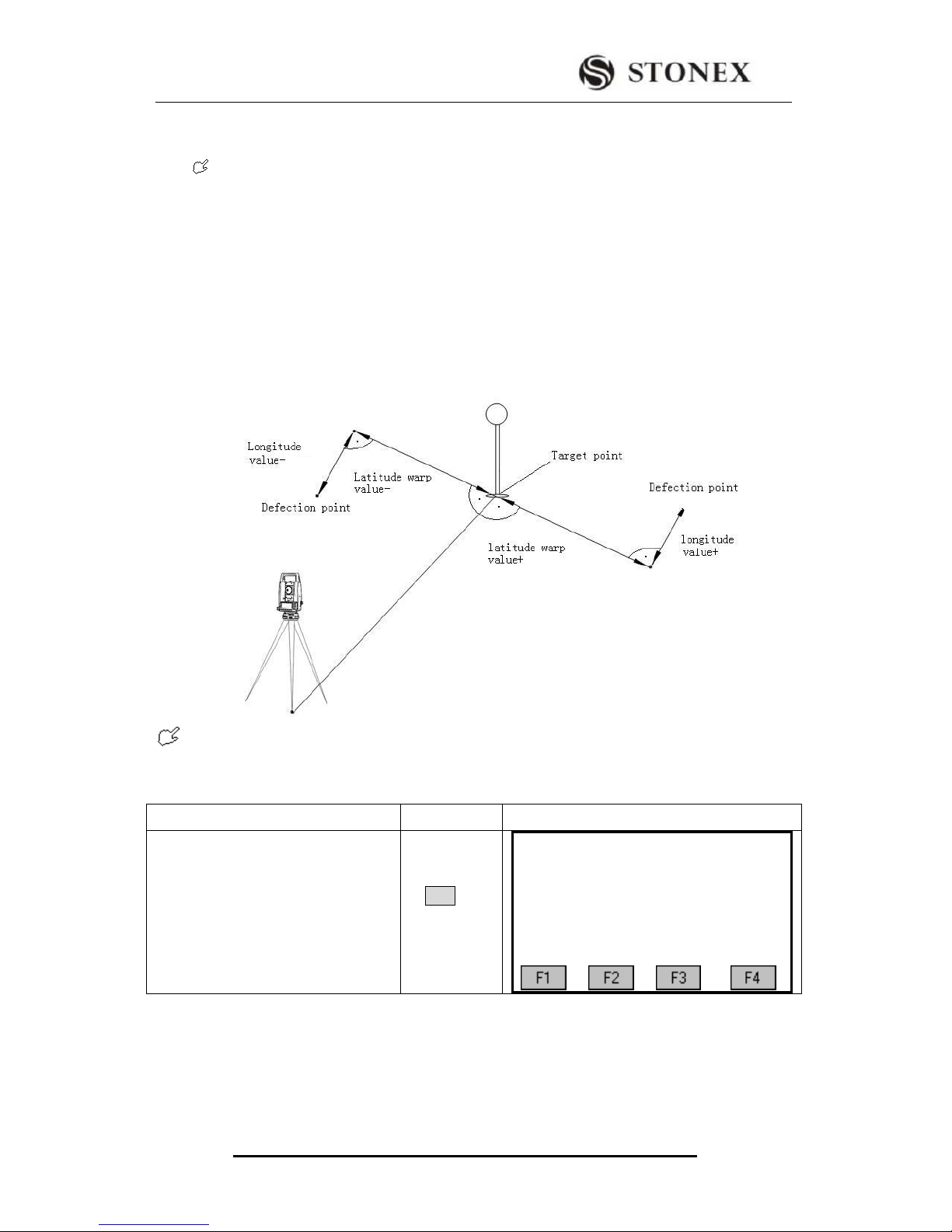
STONEX R2
45
the display of vertical angle is unstable. You can switch off the auto tilt correction
function of vertical angle.
If the mode of auto correction has been activated, (single axis, see “4.4 Main
Settings”), in the condition that the instrument has not been leveled, the program will
demand that the instrument must be leveled at first, so as to enter other functions.
4.2 TARGET OFFSET
When it is not possible to set up the reflector or aim the target point directly, this function
will perform helpfully. Enter the offset values (length, cross and/or height offset). The
values for the angle and distances can be calculated directly for the target point.
If the height offset value is plus, it indicates that the offset point is higher than the
measurement point.
OPERATION STEPS:
OPERATIONAL STEPS
OPERATION
DISPLAY
① Press [FNC] to enter into the
Function menu.
FNC
【Function】1/4 ▼
F1 Level (1)
F2 Target Offset (2)
F3 Delete Last Record (3)
F4 Main Settings (4)
Page 50
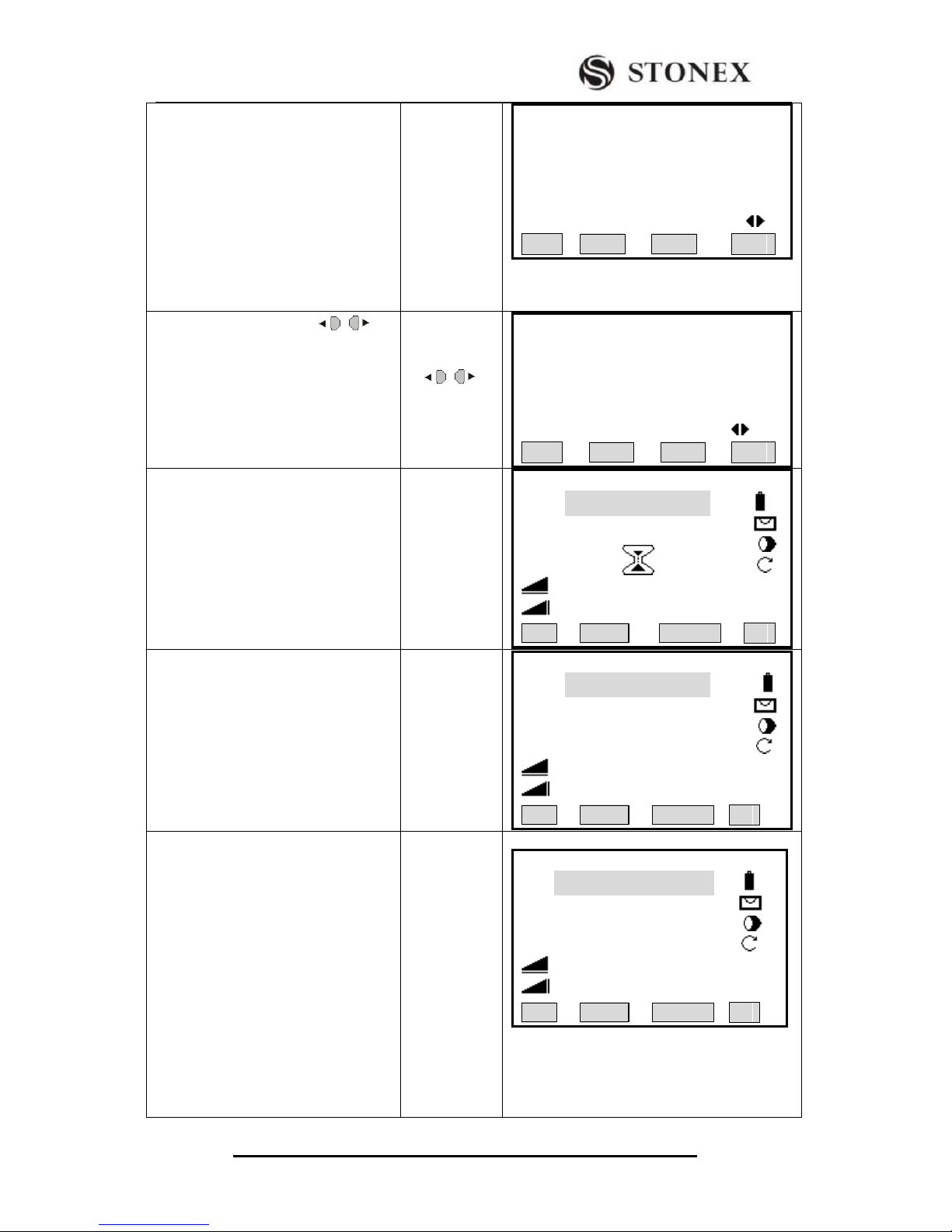
STONEX R2
46
②Press [F2] to enter into Target Offset
function.
Input the offset values (length, cross
and/ or height offset values).Define the
period for which the offset is to apply.
Press [F1] (OSET) to set eccentricity
to zero.
Press [F4] to confirm.
[F2]
+
Input
offset values,
period of
applicability
+[ENT]
+[F4]
【Target Offset】
Input Offset!
T_Offset : 0.000m
L_Offset : 0.000m
H_Offset : 0.000m
MODE: 0set After REC
0SET OK
③ Press navigation key to
select the period of applicability. The
modes available are: 0Set After REC
and Permanent.
After finishing all the settings, press
[F4] to save.
+
[F4]
【Target Offset】
Input Offset!
T_Offset : 0.000m
L_Offset : 0.000m
H_Offset : 0.000m
MODE: 0set After REC
0SET OK
④ The program calculates the
corrected values and returns to the
application from which the offset
function was started.
Collimate the center of reflector and
press [F2] to start measuring. ‴1)
[F2]
【Measure】 1/4
PtID: A2
R.HT: 1.500 m
HZ: 0°00′00″
V: 90°10′50″
: ---.--- m Ⅰ
: ---.--- m
All DIST RECORD ↓
⑤The corrected angle and distances
are displayed when a valid distance
measurement has been triggered or
exists.
【Measure】
PtID: A2
R.HT: 1.500 m
HZ: 0°00′00″
V : 90°10′50″
: 5.568 m Ⅰ
: 3.689 m
All DIST RECORD ↓
⑥When “0set After REC” is selected:
If [All] is started, the program will
display the data (the target point)
which is calculated by adding the
measured result and the offset
correction.
If [DIST] is started, you must restart
measurement after pressing
[RECORD] to display the actual value
of the measurement point.
Displays the Rec. data beforehand.
Restart measurement, displaying the data of
measurement point:
【Measure】
PtID: A2
R.HT: 1.500 m
HZ: 0°00′00″
V: 90°10′50″
: 5.568 m Ⅰ
: 3.689 m
All DIST RECORD ↓
Page 51
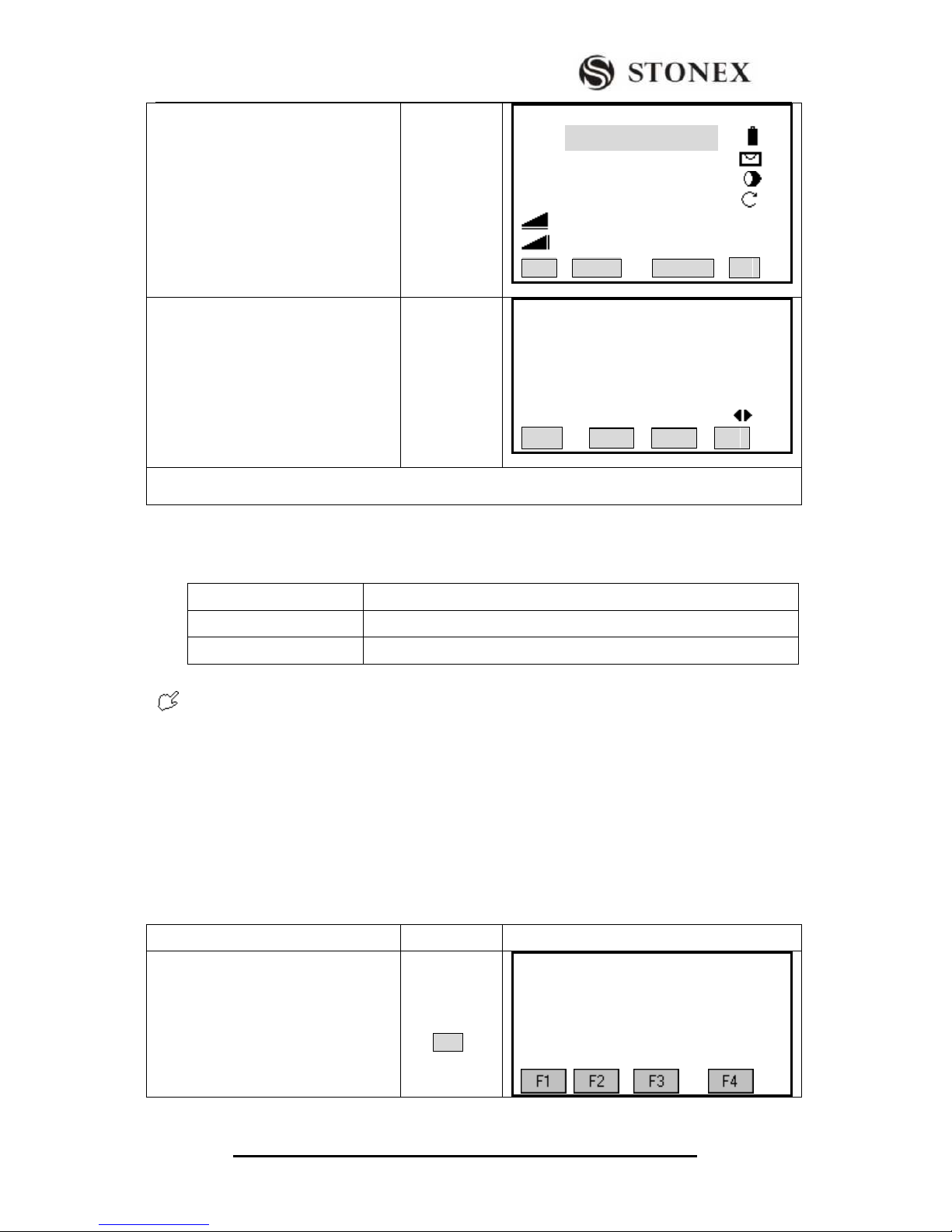
STONEX R2
47
When the “Permanent” is selected, the
program will always display the data
added the offset correction.
【Measure】
PtID: A2
R.HT: 1.500 m
HZ: 0°00′00″
V: 90°10′50″
: 2.568 m Ⅰ
: 1.689 m
All DIST RECORD ↓
⑦ If there is no more point of target
offset to measure, repeat step ① to
restart the Target Offset function.
【Target Offset】
Input Offset!
T_Offset : 0.000m
L_Offset : 0.000m
H_Offset : 0.000m
MODE: Set After REC
0SET OK
‴1) If the coordinate of target point is needed to calculate, please set the coordinate of station, heights of
instrument and reflector, backsight point, etc.
The period of applicability can be set as follows:
MODE
EXPLANATION
0set After REC
The offset values are set to 0 after the point is saved.
Permanent
The offset values are applied to all further measurements.
The offset values are always reset to 0 when the application is quit.
4.3 DELETING LAST RECORD
This function deletes the last recorded data block, which can be either a measurement
block or a code block.
Deleting the last record is irreversible!
Only records recorded during measurement can be deleted.
OPERATION STEPS:
OPERATIONAL STEPS
OPERATION
DISPLAY
① Press [FNC] to enter into the
Function menu.
FNC
【Function】1/4 ▼
F1 Level (1)
F2 Target Offset (2)
F3 Delete Last Record (3)
F4 Main Settings (4)
Page 52
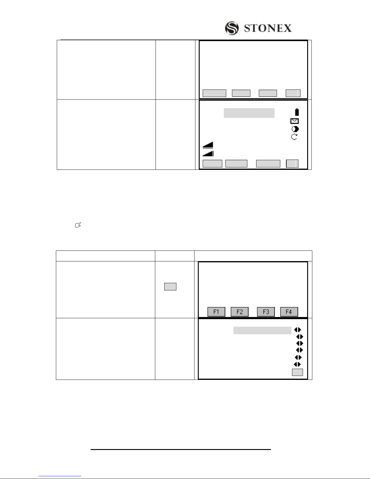
STONEX R2
48
②Press [F3] to delete the last record,
as shown on the right.
[F3]
Sure delete final record?
CANCEL OK
③Press [F4] to confirm the deleting.
If not, press [F1] (CANCEL), the
program will return to Measure
function.
【Measure】
P + ID: A2
R.HT: 1.500 m
HZ: 0°00′00″
V: 90°10′50″
: ---.--- m Ⅰ
: ---.--- m
All DIST RECORD ↓
4.4 MAIN SETTINGS
This menu enables extensive user-specific settings in order to adapt the instrument to their
own requirements.
You can rewrite some important settings.
You can also start this function by selecting “Settings” in “Menu”.
OPERATION STEPS:
OPERATIONAL STEPS
OPERATION
DISPLY
① Press [FNC] to enter into the
Function menu and select “Main
Settings”, or press [MENU] and select
“Settings”.
FNC
【Function】1/4 ▼
F1 Level (1)
F2 Target Offset (2)
F3 Delete Last Record (3)
F4 Main Settings (4)
② Press [F4] to enter into Settings
function.
[F4]
【Setting】1/4 ▼
Contrast: 4
TriggerKey: OFF
User Key: Light
V-Setting: Zenith
Tilt Crn: OFF
Coll. Crn: OFF
SET
Page 53
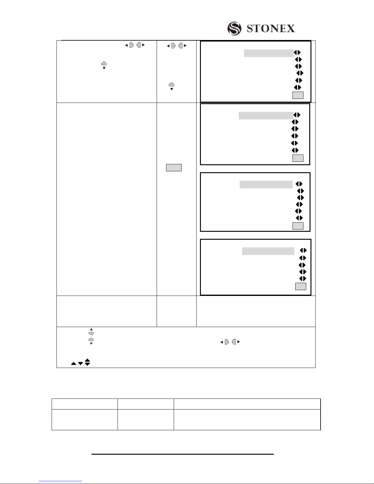
STONEX R2
49
③ Press navigation key to
select other modes of this setting, and
press [ENT] or to move on to the
next setting. ‴1)
+
[ENT]
or
【Setting】1/4 ▼
CONTRAST: 4
TriggerKey OFF
User Key Light
V SETTING Zenith
Tilt Grn : OFF
Coll. Crn : OFF
SET
④Press [PAGE] to display other pages.
Repeat step ③ on other items to be
set.
PAGE
【Setting】2/4 ▼
Sector Beep: OFF
Beep : OFF
HZ<=> Right Angle
Face Def. VK-Left
Data Output : Intern
Auto-Off : ON
SET
【Setting】3/4 ▼
AngReading: 0°00′01″
Angle Unit : dd.mm.ss
DistReading: 1mm
Dist. Unit: Meter
Tenp. Unit : C
Press Unit hPa
SET
【Setting】4/4 ▲
GSI 8/16 : GSI 16
Mask 1/2 : Mask 2
Coord Mask: X/N Y/E
NEH/ENH: NEH
Code Rec.: Save before
SET
⑤After all settings are done, press
[F4] (SET) to save, and quit the
Settings menu.
‴1) Press to move the cursor upward and downward; press to select other modes in the
item.
‴2) , , indicate that there are some pages to select by pressing [PAGE].
Detailed instruction to the Settings is shown as follow.
FUNCTION
OPTION
EXPLANATION
Contrast
1~8
Setting the display contrast in 10% steps. Customers can
adjust the display to best status through this function.
Page 54

STONEX R2
50
TriggerKey
All/ Dist/OFF
The trigger key is right above the Power Key.
OFF Trigger key deactivated.
All Trigger key with same function as the [All] key.
Dist Trigger key with same function as the [Dist] key.
User Key
Light/Level/HT
Transfer/Offset/
Code/Dist.Unit/
Angle Unit/ Hidden
Pt/Delete Rec./
Tracking/Check Tie/
Settings
One function from the Function menu. Customers can
designate the [USER] key according the using frequency
and habit.
V-Setting
Zenith/ Horizon/
V - (%)
The “0” orientation of the vertical circle can be either
selected for the zenith, the horizontal plane or in %.
Zenith: Zenith=0°; Horizon=90°
Horizon: Zenith=90°; Horizon=0°
V-(%): 45°=100%; Horizon=0°
If the V-% value increases rapidly and exceed 300%,
it displays as “--.--%”.
Tilt Crn.
1- axis / OFF
²OFF: Tilt compensation is switched off.
²1-axis V-angle relate to the plumb line.
If the instrument is set on an unstable base (e.g. shaking
platform, ship, etc.) the compensator should be switched
off. This avoids the compensator drifting out of its
measuring range and interrupting the measuring process by
indicating an error.
The compensator setting remains active even after the
instrument is switched off.
Coll Crn.
ON/OFF
²ON : HZ Collimation is switched on.
²OFF: HZ Collimation is switched off.
If option “Coll Crn.” is active, each measured HZ angle is
corrected.
For normal operation, the HZ Collimation remains
switched on.
See “10. Check and Adjust” for detailed instruction.
Sector Beep
ON/OFF
² ON: Sector Beep sounds at right angles (0°, 90°, 180°,
270°, or 0, 100, 200, 300 gon)
²OFF: Sector Beep is switched off.
Page 55

STONEX R2
51
Beep
ON/OFF
The beep is an acoustic signal after each key stroke.
ON: Beep switched on.
OFF: Beep switched off.
HZ <=>
Right Ang / Left
Ang
HZ Incrementation Direction:
Right Ang: Set right HZ for “clockwise direction
measurement”.
Left Ang: Set left HZ for “Counter-clock direction
measurement”.
FaceⅠ Def.
VK-Left/
VK- Right
Defines the telescope face I in relation to the position of
the V circle.
Data Output
Intern / RS232
²Intern: All data is recorded in internal memory.
²RS232: Data is recorded via the serial interface. With
this aim, a data storage device must be connected.
Auto - OFF
ON/OFF
²ON: The instrument is switched off after 20 minutes
without any action (= no key pressed; V and HZ angle
deviation <3‟/+600cc).
²OFF: The instrument is switched on permanently. Battery
discharges quicker.
Min Reading
The displayed angle format can be selected in three
grades.
²For 360° ′ ″: 0°00′01″/0°00′05″/0°00′10″
²For 360°: 0.0001°/0.005°/0.0010°
²For gon: 0.0001gon/0.0005gon/0.0010gon
²For mil: 0.01mil/0.05mil/0.10mil
Angle Unit
dd. mm. ss
/ deg/ gon/ mil
²° ′ ″(degree, sexagesimal), possible angle values: 0°~
359°59′59″
²DD(degree, decimal), possible angle values:0º~359.9999º
²gon, possible angle values:0gon~399.9999gon
²mil, possible angle values:0mil~6399.99mil
The setting of the angle units can be changed at any time.
The actual displayed values are converted according to the
selected unit.
Dist. Unit
Meter / US-ft /
INT-ft / ft – in 1/8
²M Meter
²US-ft Us-feet
²INT-ft International feet
²ft-in 1/8 US-feet-inch-1/8 inch
Page 56
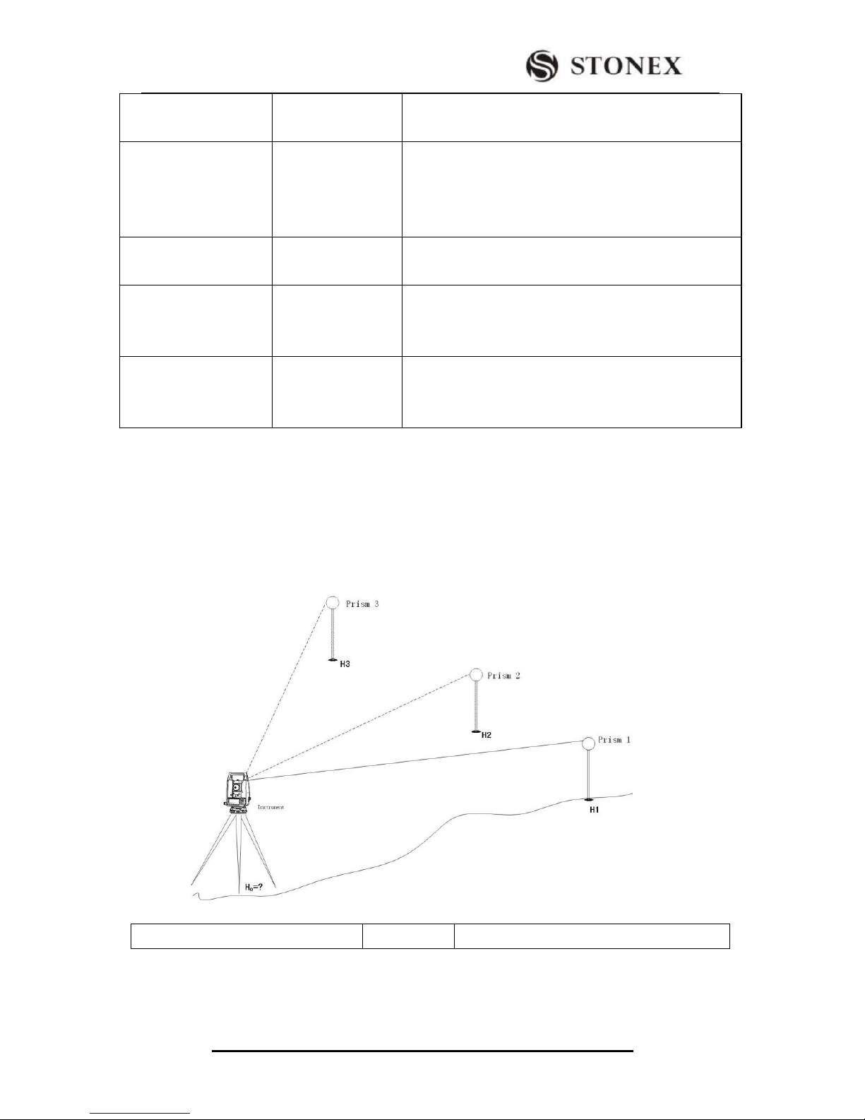
STONEX R2
52
Temp. Unit
‵ / ℉
²‵ Degree Celsius
²℉ Degree Fahrenheit
Press Unit
hPa/mbar/mmHg/in
Hg
²hPa Hecto Pascal
²mbar Milliba
²mmHg Millimeter mercury column
²inHg Inch mercury column
Code Rec.
Save before /
Save after
Sets if the code block is saved before or after the
measurement (see “3.3.4 Coding”)
GSI 8/16
GSI 8/ GSI 16
Select GSI output format.
GSI 8: 81..00+12345678
GSI 16: 81..00+1234567890123456
Mask1/2
Mask1/ Mask2
Select GSI output mask.
²Mask1:PtlD, Hz, V, SD, ppm+mm, hr, hi
²Mask2:PtlD, Hz, V, SD, E, N, H, hr
4.5 HEIGHT TRANSFER
This function determines the height of the instrument from measurements to a maximum
of 5 target points with known heights, in two faces.
While measuring to several targets with known heights, the improvement is indicated in
the “delta” value.
OPERATION STEPS:
OPERATIONAL STEPS
OPERATION
DISPLAY
Page 57
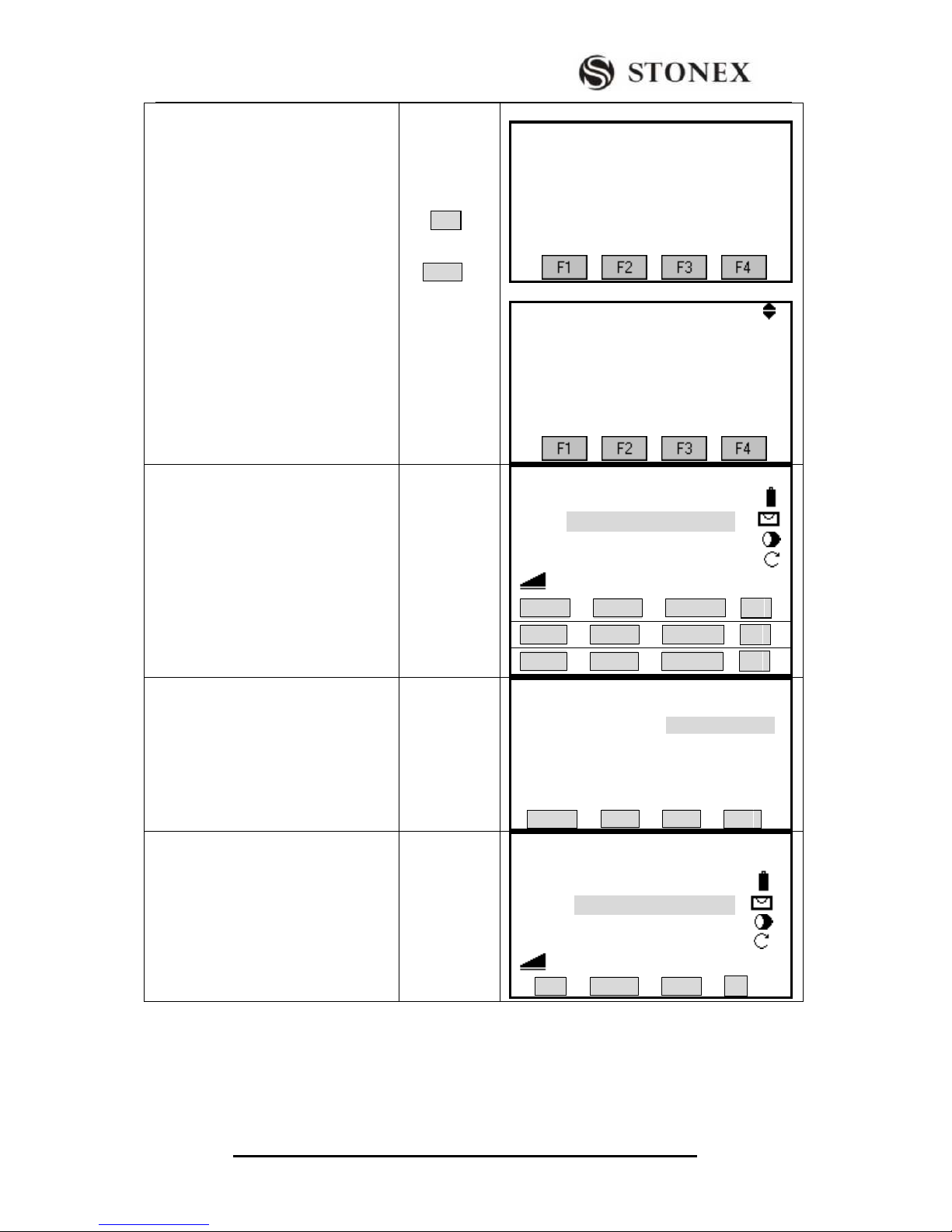
STONEX R2
53
① Press [FNC] to enter into the
Function menu. Press [PAGE] to turn
to Page 2.
FNC
+
PAGE
【Function】1/4 ▼
F1 Level (1)
F2 Target Offset (2)
F3 Delete Last Record (3)
F4 Main Settings (4)
【Function】 2/4
F1 Height Transfer (5)
F2 Hidden Point (6)
F3 Free- Coding (7)
F4 Check Tie (8)
② Press [F1] to enter into Height
Transfer function.
[F1]
【Height Transfer】 1
Select Target Meas!
Pt ID: --- ---
R. HT: 1.500 m
H / Z : ---.--- m
: ---.--- m Ⅰ
All EDM SEARCH ↓
LIST DIST RECORD ↓
EHN INS.HT VIEW |←
③Press [F4](↓) twice to display the
third page of soft keys. Press [F2] to
enter into the settings of instrument
height.
[F4]
+
[F4]
+
[F2]
【Height Transfer】
Stn. Pt.
Ins. HT: 2.000 m
X0/N0 : 100.000 m
Y0/E0 : 100.000 m
H0 : 10.000 m
BACK OK
④ Input the current instrument height,
and press [F4] to return to the screen of
Height Transfer.
Input
instrument
height
+
[F4]
【Height Transfer】
Height Transfer 1
Select Target Meas!
Pt. ID: --- ---
R.HT: 1.500 m
H/Z: ---.--- m
: ---.--- m Ⅰ
EHN INS.HT VIEW |←
Page 58
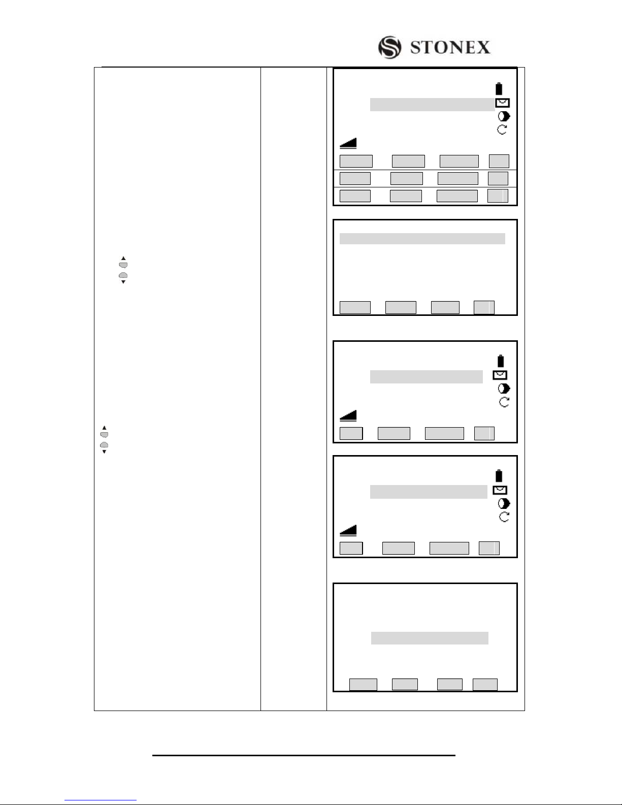
STONEX R2
54
⑤Select the known point and input the
reflector height.
The amount of known points is
shown on the upper-left corner of the
screen.
There are 3 ways to select known
points.
A:Press [LIST], and press navigation
key to call up the needed point from
the job. Press [ENT] to return to the
screen of Height Transfer
measurement.
B:Input the known point ID and press
[SEARCH] to search whether there is
such a point ID in the job. Be there
some points with the same ID, press
to select the point needed.
Press [ENT] to return to the screen of
Height Transfer measurement.
C: You may also input a point ID
which does not exist, and press [ENH].
Then input the height of the point, save
the data and return to the screen of
Height Transfer measurement.
[F1]
Input known
point, prism
height
A:Press [LIST]:
B:Input point ID to the known point, press
[SEARCH]
C:Input the ID which does not exist, and press
[ENH]
【Height Transfer】 1
Select Target Meas!
Pt ID: --- ---
R. HT: 1.500 m
H / Z : ---.--- m
: ---.--- m Ⅰ
All EDM SEARCH ↓
LIST DIST RECORD ↓
EHN INS.HT VIEW |←
【Pt. Search 】 1/254
1 Known
2 Known
3 Known
4 Known
5 Known
6 Known
VIEW EHN JOB ↓
【Height Transfer】 1
Select Target Meas!
Pt ID: 1
R. HT: 1.500 m
H / Z : ---.--- m
: ---.--- m Ⅰ
All EDM SEARCH ↓
【Height Transfer】 1
Select Target Meas!
Pt ID: 1
R. HT: 1.500 m
H / Z : ---.--- m
: ---.--- m Ⅰ
All DIST SEARCH ↓
【Height Transfer】
PtID: SA
H : ---.--- m
BACK SAVE
Page 59
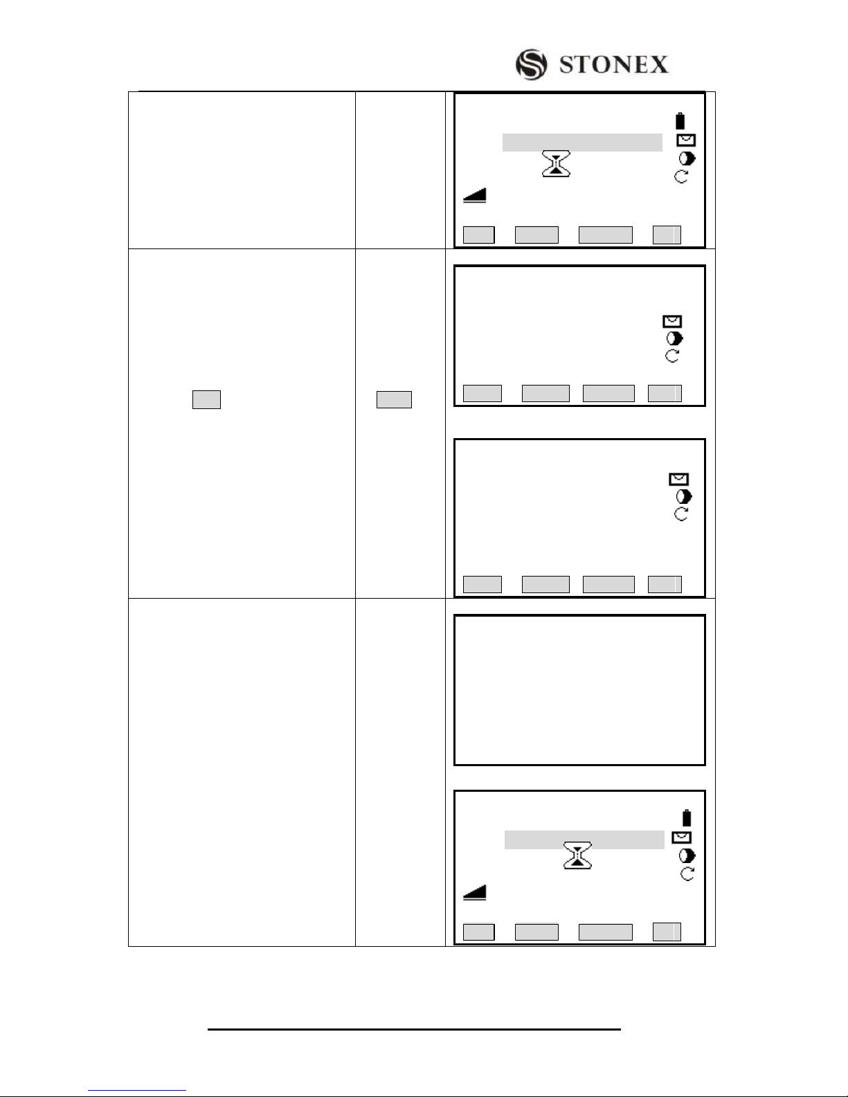
STONEX R2
55
⑥When the screen displays the height
of known point, press [F1](All) or
[F2](DIST) + [F3](RECORD) to start
measuring. The height of station can be
calculated.
[F1]
Or
[F2]
+
[F3]
【Height Transfer】 1
Select Target Meas!
Pt ID: 1
R. HT: 1.500 m
H / Z : 0.0000 m
: ---.--- m Ⅰ
All DIST SEARCH ↓
⑦ Press PAGE to turn to Page 2 to
display the measurement result.
PAGE
【Height Transfer】 1/2
HT. Tran. Result
Stn. Pt. :
Corr. : 1.500 m
No. Pts : 10.0000 m
Add Pt FACE BACK OK
【Height Transfer】 2/2
HT. Tran. Result OCC1
Stn. Pt. :
X0/N0 : 1.500 m
Y0/E0 : 10.0000 m
H0 : 8.250 m
No. Pts : 10.0000 m
St. Dev .:
Add Pt FACE BACK OK
⑧Press [F2] (FACE) to measure the
same target in second face.
If you don‟t need to face measure
the same point, press [F1] (Add Pt) to
add a measurement of the known
point.
[F2]
【Height Transfer】
Turn to face!
【Height Transfer】 1
Select Target Meas!
Pt ID: 1
R. HT: 1.500 m
H / Z : 10.0000 m
: ---.--- m Ⅰ
All DIST SEARCH ↓
Page 60
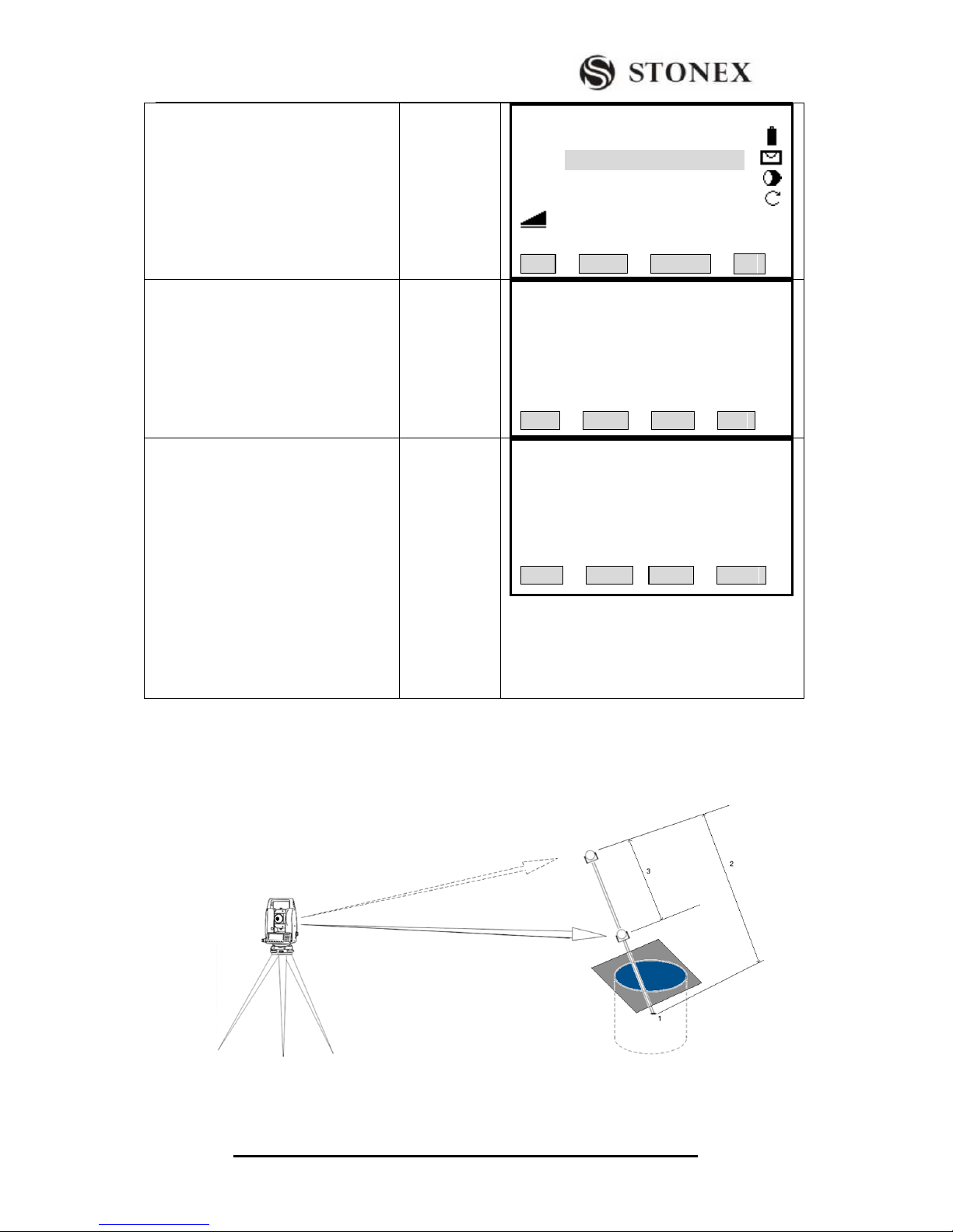
STONEX R2
56
⑨After the Face measurement, return
to the result menu, and press [F1](Add
Pt), follow the steps ⑤ ~ ⑧ to
continue the measurement of the next
known point.
[F1]
【Height Transfer】 1
Select Target Meas!
Pt ID: 1
R. HT: 1.500 m
H / Z : 10.0000 m
: ---.--- m Ⅰ
All DIST SEARCH ↓
⑩ This function provides the
measurement of a maximum of 5 target
points in two faces. After all
measurements are completed, press
[F4] to confirm the result in the menu
of Height Transfer.
[F4]
【HT-Tran. Result】 1/2 ▼
HT. Tran. Result OCC1
Stn. Pt. :
H0 : 8.250 m
Corr. :
No. Pts : 10.0000 m
AddPt FACE BACK OK
⑴
[F1](BACK): Back to Height Transfer
Result menu.
[F2](OLD): Remains the previous
station height.
[F3](AVE): the average value of the
old and new value of station height to
set the station height.
[F4](NEW):Takes the value calculated
in the program as the station height.
【H0 Exist】
Stn. Pt. :
Old H0 :
New H0 :
△H0 : 8.250 m
BACK OLD AVE NEW
4.6 HIDDEN POINT MEASUREMENT
The program allows measuring to a point that is not directly visible, using a special
hidden-point rod.
The Picture shown above implies:
Page 61
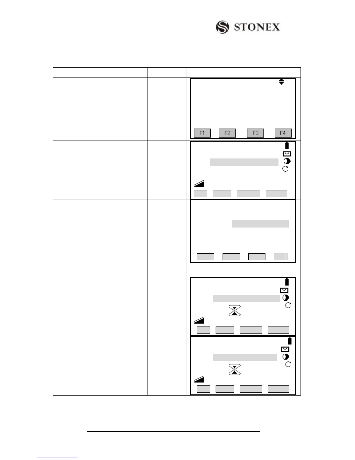
STONEX R2
57
1. E, N, H of Hidden Point
2. Rod Length
3. Distance R1-R2
OPERATIONAL STEPS
OPEATION
DISPLAY
① Press [FNC] to enter into the
Function menu. Press [PAGE] to turn
to Page 2.
[FNC]
+
[PAGE]
【Function】 2/4
F1 Height Transform (5)
F2 Hidden Point (6)
F3 Free-Coding (7)
F4 Check Tie (8)
②Press [F2] to enter into the Hidden
Point function.
[F2]
【Hidden Point】
Meas first prism!
PtID: ---.---
HZ: 0°00′00″
V: 87°40′00″ Ⅰ
: ---.--- m Mem.
All DIST RECORD RDD/ED
③ Press [F4] (ROD/ED) to set the
total length of the rod, the distance
between R1 and R2, and the
measurement toleration ‴ 1). After
entering one setting, press [ENT] to
move to the next item. Press [F4] to
return to Hidden Point menu after
finishing all the settings.
[F4]
【Rod Length Settings】
Rod Length: ---.---
Dist R1-R2: ---.--Meas. Tol : ---.---
OK
④ Enter the point ID of the first
reflector, collimate the reflector and
press [F1](All) or [F2] (DIST) +
[F3](RECORD) to start measurement.
Input PtID1
+
[F1]
Or[F2]
+
[F3]
【Hidden Point】
Meas first prism!
Pt. ID: 1
HZ: 0°00′00″
V : 87°40′00″ Ⅰ
: ---.--- m Mem.
All DIST SEARCH ROD/ED
⑤ Enter the point ID of the second
reflector, collimate the reflector and
press [F1](All) or [F2] (DIST) +
[F3](RECORD) to start measurement.
Input PtID2
+
[F1]
Or[F2]
+
[F3]
【Hidden Point】
Meas second prism!
Pt. ID: 1
HZ: 0°00′00″
V : 87°40′00″ Ⅰ
: ---.--- m Mem.
All DIST SEARCH ROD/ED
Page 62
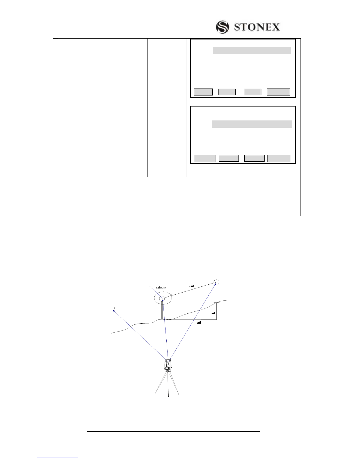
STONEX R2
58
⑥Displays the result.
If the result is unsatisfied, press [F4]
to repeat step ④ to redo the
measurement.
Press [F1] (FINISH) to save the
result, and to quit this function.
[F1]
【Hidden Point】
Pt. ID: 1
Desc. : --- --X/N : 102.205 m
Y/E : 98.021 m
H/Z : 96.247 m
FINISH REMEAS
⑦ If the result exceed the
measurement tolerance value, it will
display the Over Limit.
Press [F1]: Accepts the limit, and
displays the coordinate of hidden
point.
[F4]:Return to step ② to redo the
measurement.
【Hidden Point】
Over Limit!
Limit: 0.100 m
Diff. : 0.247 m
ACCEPT REMEAS
‴1) Rod Length: Total length of hidden-point rod.
Dist R1-R2: Spacing between the centers of reflector R1 and R2.
Meas. Tol: Limit of the difference between the given and measured spacing of the reflectors. If the
tolerance value is exceeded, the program will prompt a warning.
4.7 CHECKING TIE
Calculation and display of the slope and horizontal distance, height difference, azimuth,
grade, and coordinate differences between the last two measured points. Valid distance
measurements are required for the calculation.
Page 63
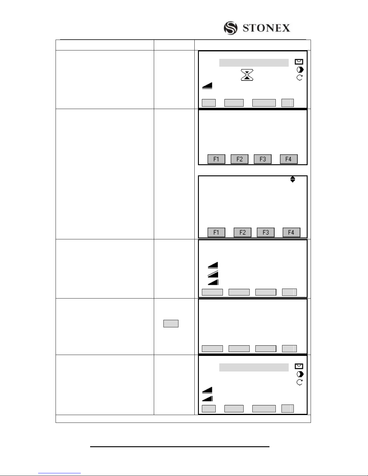
STONEX R2
59
OPERATIONAL STEPS
OPEARTION
DISPLAY
① In Measure menu, measure 2 points
that are used to check tie. ‴1)
【Measure】 1/4
Pt ID: 1
R. HT: 1.500 m
H / Z : 10.0000 m
: ---.--- m Ⅰ
All DIST SEARCH ↓
② After finishing measuring these 2
points, press soft key [FNC] to enter
into the Function menu. Then press
[PAGE] to turn to Page 2.
[FNC]
+
[PAGE]
【Function】1/4 ▼
F1 Level (1)
F2 Target Offset (2)
F3 Delete Last Record (3)
F4 Main Settings (4)
【Function】2/4
F1 Height Transfer (5)
F2 Hidden Point (6)
F3 Free- Coding (7)
F4 Check Tie (8)
③ Press [F4] to enter into Check Tie
menu. The screen displays the AZ of 2
points, and the relations of the HD, SD
and VD.
[F4]
【Check Tie】1/2 ▼
AZ: 186°28′36″
Grade: 9.0%
△ : 4.298 m
△ : 4.316 m
△ : 0.396 m
OK
④Press [PAGE] to turn to Page 2.
PAGE
【Check Tie】2/2 ▼
AZ: 186°28′36″
Grade: 9.0%
△X/N: -0.466 m
△Y/E: - 4.316 m
△H: 0.396 m
OK
⑤ Press [F4] (OK) to return to
Measure menu.
[F4]
【Measure】 1/4
Pt ID: 1
R. HT: 1.500 m
H / Z : 10.0000 m
: ---.--- m Ⅰ
: 4.316 m
All DIST SEARCH ↓
‴1) Meaning: The values cannot be calculated as there is less than 2 valid measurements.
Page 64
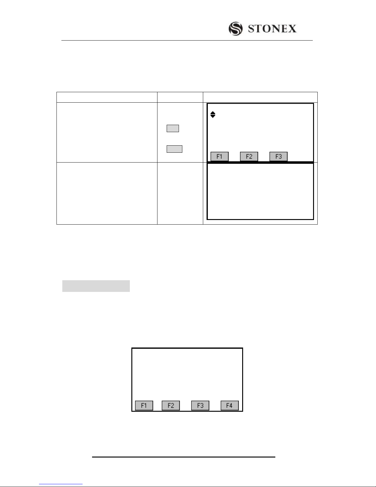
STONEX R2
60
4.8 TRACKING
Switch on or off the tracking measurement mode. The new setting is displayed for
approximately one second and then set. The function can only be activated from within
the same EDM type and prism type.
OPERATIONAL STEPS
OPERATION
DISPLAY
①Press soft key [FNC] to enter into
Function menu. Press [PAGE] twice to
turn to Page 3.
FNC
+
PAGE
【 FUNCTION 】 3/4
F1 EDM Tracking (9)
F2 Light ON/OFF (0)
F3 Laser Pointer On/Off
② Press [F1] to activate tracking
function. Screen displays as the right
picture. To deactivate tracking
function, just enter into Function menu
and press [F1] that sets the EDM
Tracking again.
Open Tracking Mode!
Every time when pressing the soft key that sets EDM Tracking function, the measurement
mode will switch between Fine [s] and Tracking.
The last active measurement mode remains set when the instrument is switched off.
5. PROGRAMS
APPLICATION PRE-SETTINGS
There are programs that precede the application programs and are used to set up and
organize measurement station data. They are displayed after selecting an application.
Users can select the start programs individually.
[*]: Settings made.
[ ]: Settings not made.
【Setting Meas】
[ * ]F1 Setting Job (1)
[ ]F2 Setting Station (2)
[ ]F3 Set Orientation (3)
F4 Start (4)
Page 65
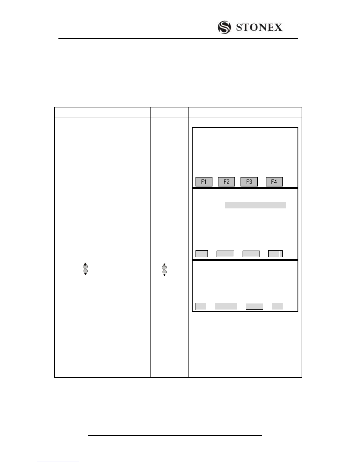
STONEX R2
61
Find further information about individual start-up programs on the subsequent pages!
5.1 SETTING JOB
All data is saved in JOBS, like directories. Jobs contain measurement data of
different types (e.g. measurements, codes, fixed points, stations, etc.) and are individually
manageable and can be readout, edited, or deleted separately.
5.1.1 Setting a New Job
OPERATIONAL STEPS
OPERATION
DISPLAY
①Press [F1] in Setting Meas menu to
enter into Setting Job menu.
[F1]
Setting Meas
[* ]Setting Job (1)
[* ]Setting Station (2)
[* ]Set Orientation (3)
F4 Start (4)
②Press [F1](LIST) to set a new job.
Press [OK] to set this job, and return to
start-up program.
[F1]
Setting Job
Job : DEFAULT
Name : -- -Date : 2011.06.30
Time : 14:10:20
Note 1 :
Note 2 :
LIST OK
③Press up and down cursor keys to
select the disk where you want to
create the file. Press [F4] (confirmed).
Disk: A local disk
Disk: B the SD card carried by the
removable disk (if the disk partition
has enough space, it will show C / D ...
disk, does not support Chinese file
name and the Chinese directory)(If SD
card is installed,“Disk:B ”will show
here)
[F4]
View job
Disk:A
Disk:B
Attr. Format OK
Page 66
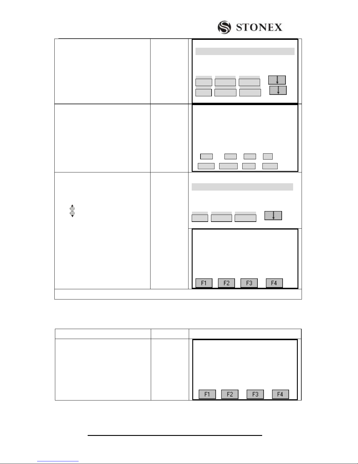
STONEX R2
62
④Display file list, press [F4] (P1 ↓)
to show the second page of features.
Press [F1] (new), create a working
file.)
[F4]
View Job
PLAN.RAW 80B 10-00
STON.RAW 90B 10-08
DDDO.RAW 93B 10-09
Attr. PrevPG NextPG
NEW Rename DELETE
⑤Enter job name, and operator name
and so on. After entering one item,
press ENT to move the cursor to the
next item to be edited.
New Meas Job
Job: ----------Name: ----------Date: 2011.06.15
Time: 16:08:44
Note 1:
Note 2:
OK
INSERT DELETE Clear ALPH
⑥Finish inputting, press [F4] (OK) to
save job, then create the file
successfully. And return to view job.
Press to select the file name created
just now, and then press [ENT] to set it
as current job. In front of the item
finished setting, there will be a"*".)
View Job
PLAN.RAW 80B 10-00
STON.RAW 90B 10-08
DDDO.RAW 93B 10-09
Attr. PrevPG NextPG
Setting Meas
[* ]Setting Job (1)
[ ]Setting Station (2)
[ ]Set Orientation (3)
F4 Start (4)
‴1) The establishment date and time will be added to the system automatically.
5.1.2 Calling up a Job from Internal Memory
When there is existed job in internal memory, you can call up and set it as the current job.
OPERATIONAL STEPS
OPERATION
DISPLAY
① Press [F1] in the Setting Meas
menu to enter into Setting Job
function.
[F1]
【Setting Meas】
[ ]F1 Setting Job (1)
[ ]F2 Setting Station (2)
[ ] F3 Set Orientation (3)
F4 Start (4)
Page 67
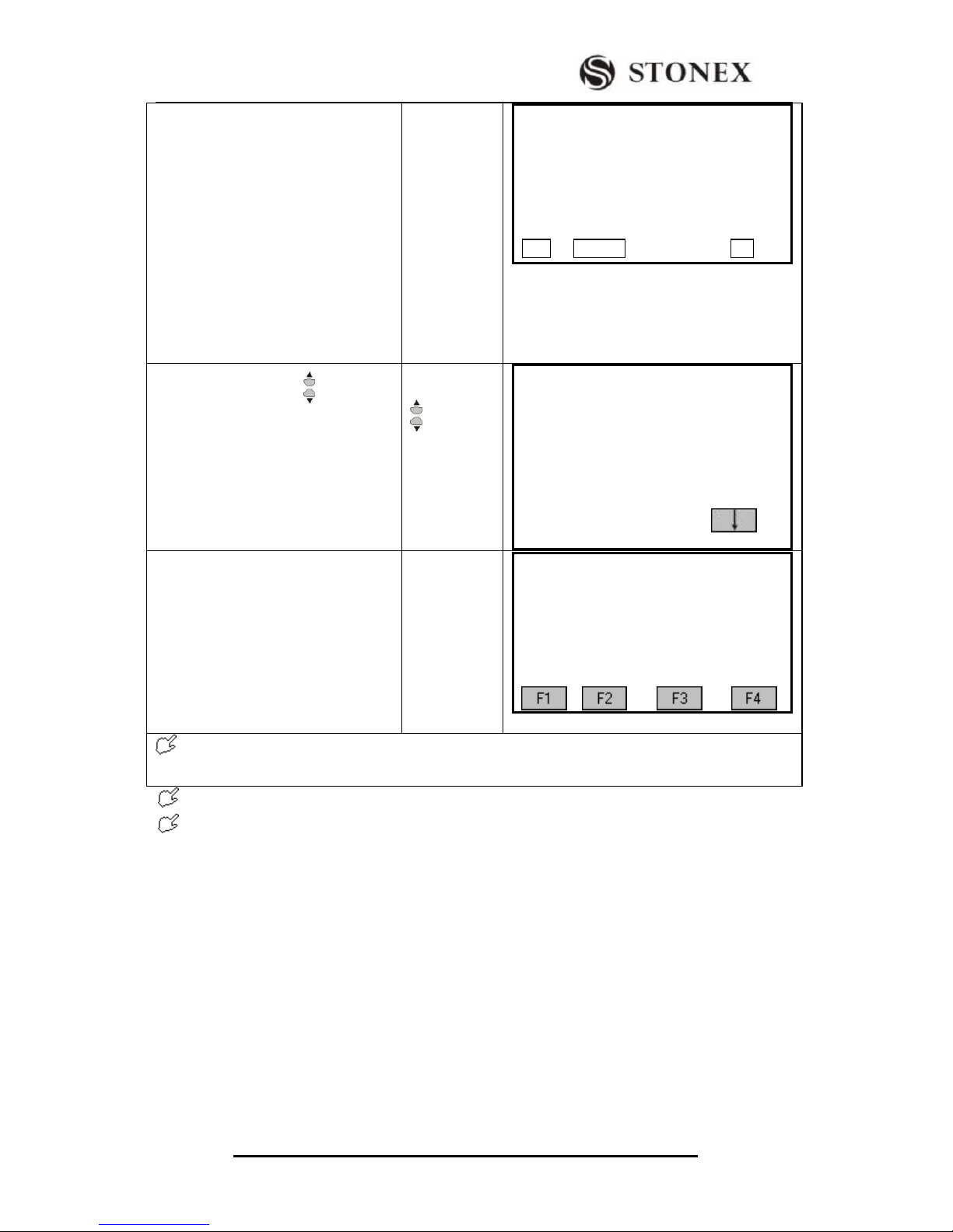
STONEX R2
63
②Press [F1] (list) into the disk list. ‴
1)
Disk: A local disk
Disk: B insert the SD card (if the
disk partition has enough space, it will
show C / D ... disk, does not support
Chinese file name and the Chinese
directory)
Press [F4] (OK) to enter the disk
where the job to be called. )
[F1]
+
[F4]
View job
Disk:A
Disk:B
Attr. Format OK
③Press navigation key( ) to view all
the jobs in internal memory. When
selecting the needed job, press [F4]
(ENT) to set it as the current job, and
then back to the job setting interface.
+
[F4]
View Job
PLAN.RAW 80B 10-00
STON.RAW 90B 10-08
DDDO.RAW 93B 10-09
Attr. PrevPG NextPG
④ Screen displays "Job set ready!"
Return to Setting Meas. The project
will be set in front of "*" logo The
screen displays “Job set already!” and
returns to Setting Meas menu. In front
of the item finished setting, there will
be a"*".
【Setting Meas】
[*] F1 Setting Job (1)
[ ] F2 Setting Station (2)
[ ] F3 Set Orientation (3)
F4 Start (4)
Note: It is forbidden to disconnect the SD card during the process of files in it, otherwise,it may lead
to data loss or damage.
All subsequent recorded data is stored in the current job.
If no job was defined and an application was started or if in “Measure” [All] or [REC]
was triggered, then the system automatically creates a new job and names it “DEFAULT”.
5.2 SETTING STATION
Each coordinate computation relates to the currently set station.
At least plan coordinates (E, N) are required for the station. If necessary, the station height
can be entered. The coordinates can be entered either manually or read from the internal
memory.
Page 68
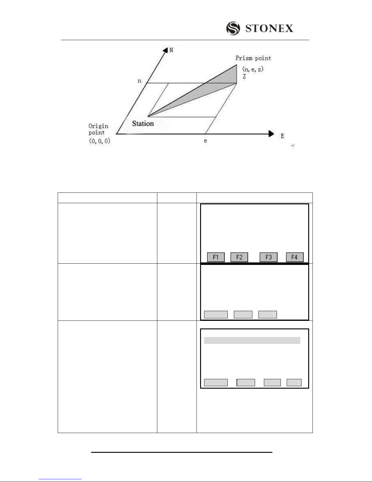
STONEX R2
64
5.2.1 Calling up a Job from Internal Memory-[SEARCH]
STEPS: 1. Select a PtID stored in internal memory.
2. Input instrument height.
[OK] Sets the station.
OPERATIONAL STEPS
OERATION
DISPLAY
①Press [F2] in Setting Meas menu to
enter into Setting Station menu.
[F2]
【Setting Meas】
[*] F1 Setting Job (1)
[ ] F2 Setting Station (2)
[ ] F3 Set Orientation (3)
F4 Start (4)
② Enter the PtID of known point and
press [ENT].‴1)
Input PtID
+
[ENT]
【Setting Station】
Input Station Pt. ID!
Stn Pt:
SEARCH LIST ENH
③Press[F1](SEARCH):
A:If the PtID exists in the job, the
screen will display as the right picture.
If there are several points, the program
will list them separately.
B:If the input PtID does not exist, the
program will imply “PtID No Exist!”,
and then display Coordinate Input
menu.
A:
B:
【Pt Search】 4
12 Known
12 Meas.
12 Meas.
12 Meas.
SEARCH ENH JOB OK
Page 69
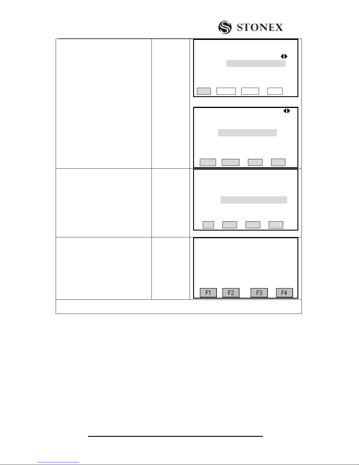
STONEX R2
65
You can call up PtID from other jobs to
set as the station. Press [F1]
(SEARCH). If the point is found, press
[OK] in Pt Search menu to set it as the
station and set the instrument height. If
the point does not exist, press [F3]
(ENH) to input the coordinate.
[0SET]: Quickly set the coordinate of
the point to zero and set it as the
station.
[ENH]: Displays the Coordinate Input
menu. Input the coordinate and save it
in the job.
【Pt Search】
Job : STONEX
Pt. ID: 56
More Job
Select job / input Pt. coord
FIND 0SET ENH LIST
【Coordinate Input】
Job: A:\STONEX.PTS
Pt. ID: 56
X/N : ----.---- m
Y/E : ----.---- m
H/Z : ----.---- m
BACK SAVE
④ The program implies to input the
instrument height. Press [ENT] to
confirm, and press [F4] to save it and
set it as the station.
[PtID]: Return to previous dialog. And
set station point.
[F4]
Input
instrument
height
+
[ENT]
[F4]
【Setting Station】
Input INS.HT!
INS.HT: 1.000 m
PtID OK
⑤ Returns to Setting Meas menu.
Settings that are made will display “*”
in the front.
【Setting Meas】
[*]F2 Setting Job (1)
[*]F2 Setting Station (2)
[ ] F3 Set Orientation (3)
F4 Start (4)
‴1)For more information about point search, please refer to “2.8 Point Search”. You can also search via
wildcard “*”. See “2.9 Wildcard Search”.
5.2.2 Calling up Known Point in Internal Memory-[LIST]
In terms of setting station PtID, you can also call it up directly from internal memory
without inserting.
Page 70
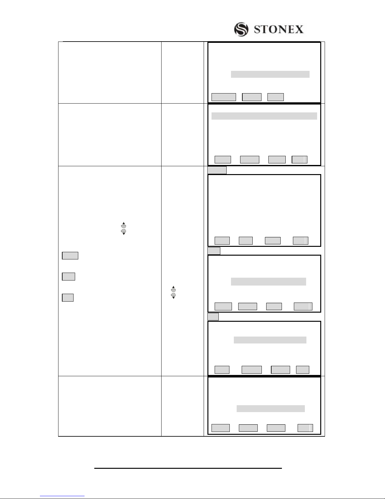
STONEX R2
66
②In Setting Station menu, press [F2]
(LIST)
[F2]
Setting Station
Input Station PtID!
Stn Pt: --- --- ---
SEARCH LIST ENH
③ Data of all known points and
measured points will be displayed.
【Point Search】
12 Known
12 Meas.
12 Meas.
12 Meas.
VIEW ENH JOB OK
④Press navigation key to select the
needed point.
VIEW: to view the coordinate
information of the point.
ENH: to input coordinate data in the
job.
JOB: to select data from other job.
VIEW :
ENH:
JOB:
【Pt Search Coord View】
Pt. ID: 56
X /N: 155.301m
Y/E: 152.361m
H/Z: 129.569m
Date: 2011.06.17
Time: 14:52:06
Start Last OK
Coord Input
Job A:\1.PTS
Pt. ID: ----.---- *
X/N : ----.---- m
Y /E : ----.---- m
H/E : ----.---- m
BACK Save
【Point Search】
Job : 1
Pt. ID: *
More Job
Select job / input Pt Coord
FIND 0SET ENH LIST
⑤ After selecting the needed point,
press [F4] (OK) to enter into INS.Ht
inserting menu.
[F4]
Input
instrument
height
+[ENT] [F4]
Setting Station
Input INS.HT!
INS.Ht: 1.000 m
PtID OK
Page 71
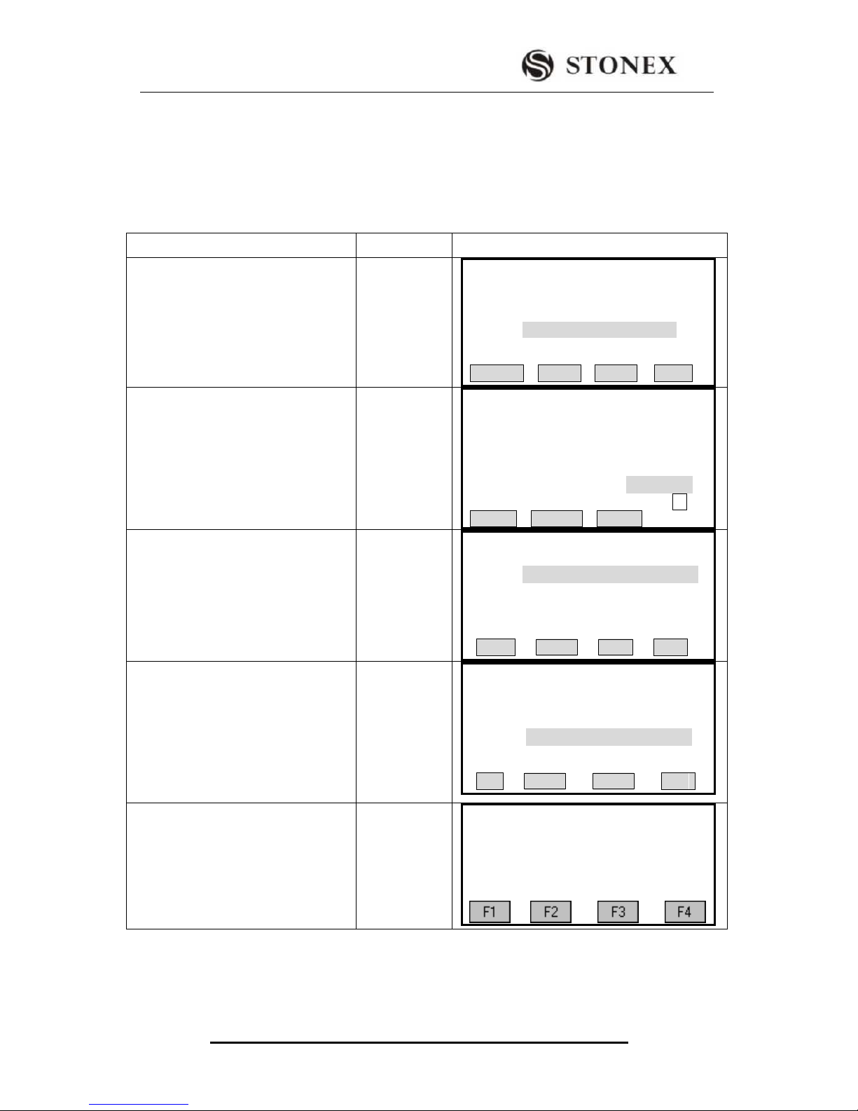
STONEX R2
67
5.2.3 Inputting Coordinate Manually
STEPS: 1.Press [ENH] to display the Input Coordinate menu.
2. Input PtID and coordinate.
3. Press [SAVE] to save the station coordinate. Then input instrument height.
If no station was set or no application started and if in “Measure” [All] or [REC] was
activated, then the last station is set as the current station.
OPERATONAL STEPS
OPERATION
DISPLAY
① Press [F3] (ENH) in Setting Station
menu.
[F3]
Setting Station
Input Station Pt. ID!
StnPt: ----.----
SEARCH LIST ENH . .
② Input PtID and coordinate. After
finishing one setting, press [ENT] to
move on to the next item.
Input PtID and
coordinate
+
[ENT]
【Coordinate Input】
Job : STONEX
Pt. ID : OCC1
X/N : 100.000 m
Y /E : 100.000 m
H/Z : ----.---- m
01
INSERT DELETE CLEAR
③Press [F4] to save station coordinate.
[F4]
【Setting Station】
Job : STONEX
Pt. ID: OCC1
X/N : 100.000 m
Y /E : 100.000 m
H : 0.000m
BACK SAVE
④ When the screen displays “Data
Save!”, input the instrument height and
press [ENT].
Input
instrument
height
+
[ENT]
Setting Station
Input INS.HT !
INS.HT: 1.000 m
PtID OK
⑤The screen returns to Setting Meas
menu. Settings that are made will
display “*” in the front.
【Setting Meas】
[*]F1 Setting Job (1)
[*]F2 Setting Station (2)
[ ] F3 Set Orientation (3)
F4 Start (4)
5.3 SETTING ORIENTATION
With the orientation, HZ-direction can be input manually or set by points with
Page 72
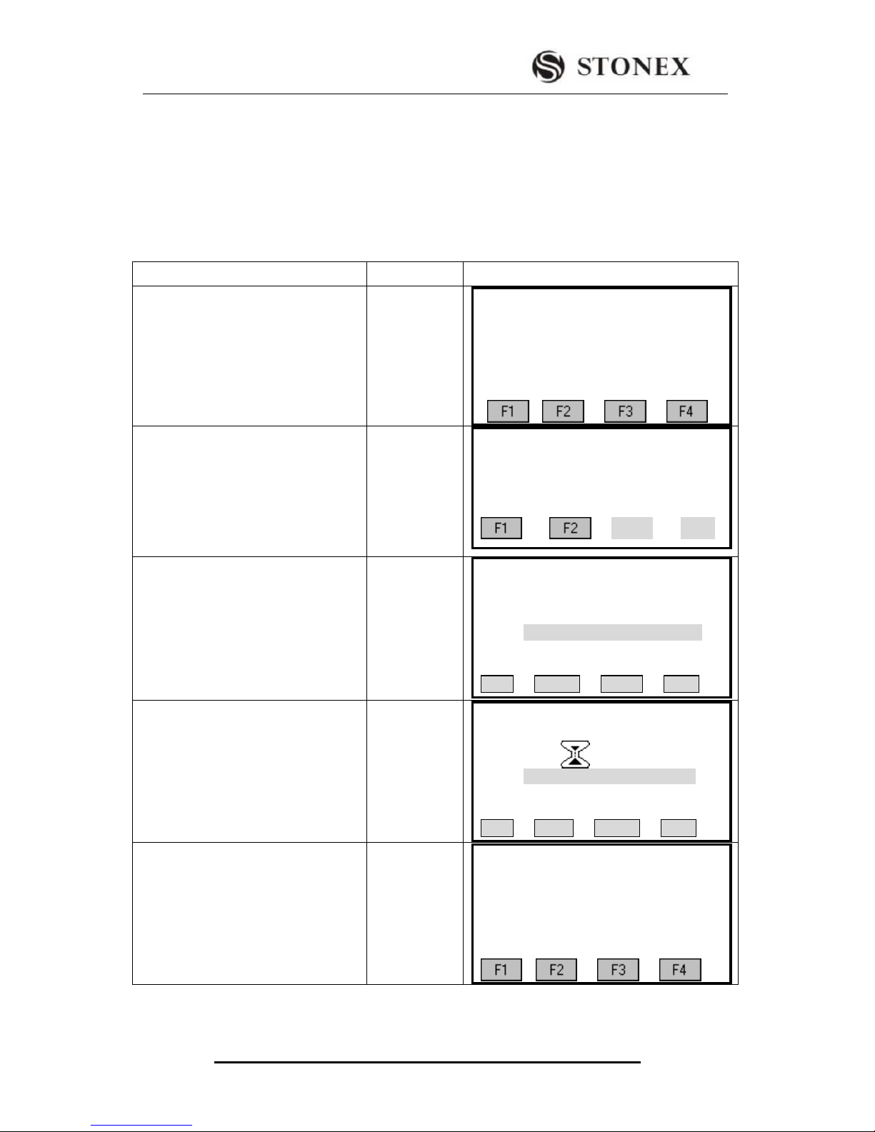
STONEX R2
68
known coordinates.
5.3.1 Manually Inputting
STEPS: 1. Press [F1] to input a random HZ-orientation.
2. Input HZ-direction, reflector height and PtID.
3. Press [All] to start measurement and set orientation.
4. Press [RECORD] to record HZ-direction and set orientation.
OPERATIONAL STEPS
OPERATION
DISPLAY
① Press [F3] in Setting Meas menu to
set the orientation.
[F3]
Setting Meas
[*]F1 Setting Job (1)
[*] F2 Setting Station (2)
[ ] F3 Set Orientation (3)
F4 Start (4)
② Press [F1] to enter into Set
Manually function.
[F1]
Orientation
F1 Set manually
F2 Known Point
③ After Collimating the backsight
point, input a random AZ value,
reflector height and PtID. After
inputting one item, press [ENT].
Input
horizontal
azimuth value
+
[ENT]
【Set manually 】
BsPt: 2
R.HT: 1.500 m
AZ: 9°11′25″
Sight BsPt Meas & Rec!
All EDM SET. OSET
④ Press [F1] (All) to start
measurement and set orientation.
[SET] : Set orientation without
activating the measurement function.
[0SET]:Set AZ to zero.
[F1]
【Set Manually 】
BsPt: 2
R.HT: 1.500m
AZ: 9°11′25″
Sight BsPt Meas & Rec!
All SET EDM OSET
⑤ The screen returns to Setting Meas
menu. Settings that are made will
display “*” in the front.
【Setting Meas】
[*]F1 Setting Job (1)
[*] F2 Setting Station (2)
[*] F3 Set Orientation (3)
F4 Start (4)
Page 73
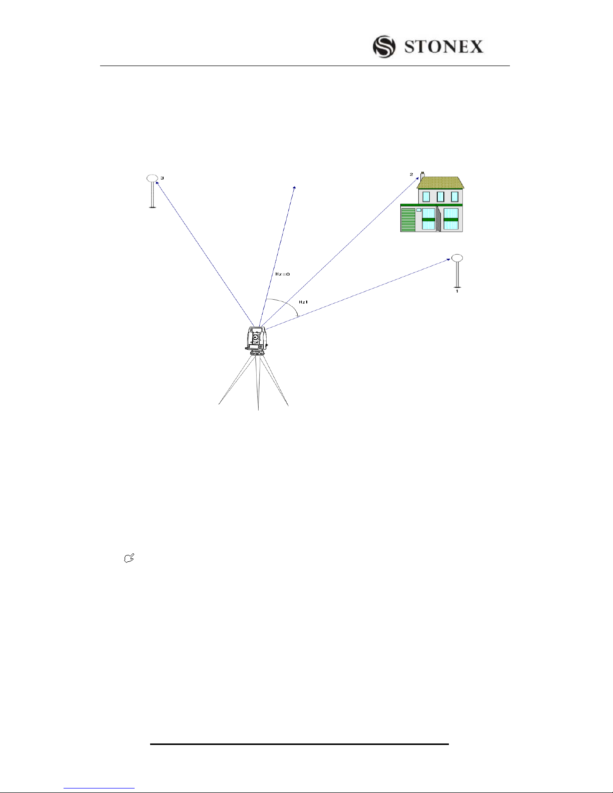
STONEX R2
69
5.3.2 with Coordinates
A target with known coordinates can also be used to determine the orientation. The
number of known points can be one or more. This series of instrument provides a method
of backsight point orientation with a maximum of 5 known points.
In the picture, 1: Backsight Point 1
2: Back Sight Point 2
3. Backsight Point 3
STEPS :1. Press [F2] to activate orientation with coordinates function.
2. Input the orientation PtID and determine the point found.
3. Input and confirm the reflector height. A maximum of 5 target points
with known coordinates can be used.
Orientation coordinates can be either obtained from the internal memory or
entered manually.
Page 74
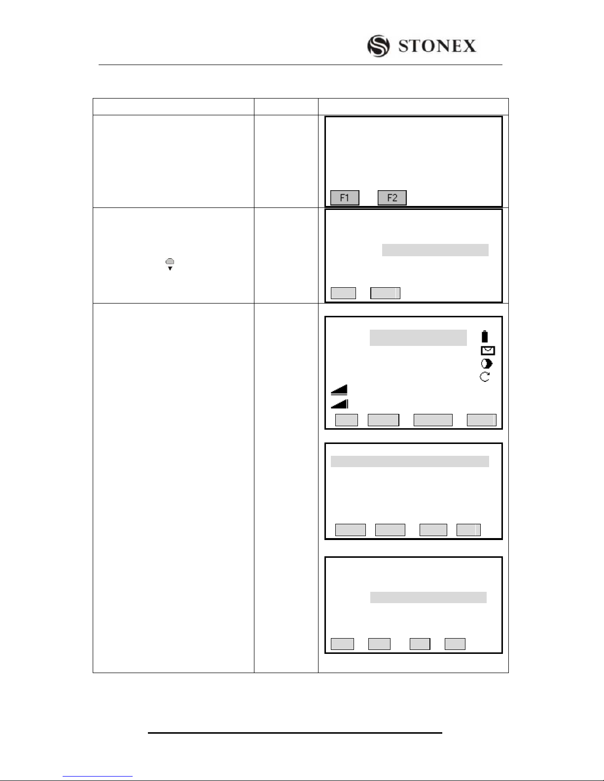
STONEX R2
70
OPERATIONAL STEPS
OPERATION
DISPLAY
① Press [F2] to select the method to
set orientation.
[F2]
【 Orientation 】
F1 Set manually
F2 Known Point
② Input the backsight PtID and press
[ENT].
If reflector height is to be input, press
navigation key to move to the
R.HT item. ‴1)
Input
backsight
PtID
+
[ENT]
【Known Pt】
Input BsPt!
BsPt : BS1
R. HT: 1.860 m
LIST ENH
③ The program automatically
searches if there is an existed PtID.
‴2)
A:If there is a unique PtID in the job,
the screen will enter into backsight
measurement menu.
B:If there is more than 1 point with
the same ID, user is requested to select
one data among them.
C:If there is no such a PtID in the job,
user is requested to input the data of
the point.
A:
B:
C:
【Known Pt 】 1/2 ▼
Bs Pt: BS1
R. HT: 1.860 m
HZ: 0°00′00″
V : 90°00′00″
: ---.--- m Ⅰ
: ---.--- m
All DIST RECORD EDM
【Pt Search 】 1/3 ▼
BS1 Known
12 Meas.
23 Meas.
VIEW ENH JOB OK
【Pt Search 】 1/3
Job : STONEX
PtID: BS1
More Job
Select Job / input Pt Coord.
FIND 0SET ENH LIST
Page 75
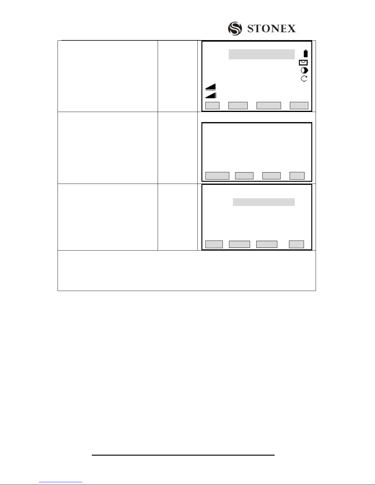
STONEX R2
71
④ Collimate Backsight Point 1, press
[F1] (All) or [F2] (DIST) to start
measurement of orientation with
coordinate.
[EDM]: change the EDM setting.
[F1]
or
[F2]
+
[F3]
【Known Pt 】 1/2 1/I ▼
Bs Pt: BS1
R. HT: 1.860 m
HZ: 0°00′00″
V : 90°00′00″
: ---.--- m Ⅰ
: ---.--- m
All DIST RECORD EDM
⑤ After each measurement, you will
be asked whether you want more
measurement. Press [OK] to return to
measurement menu and start another
measurement. Press [CANCEL] to
enter into Orientation Result menu.
‴3)
[F1]
Want More Measurement?
CANCEL OK
⑤Displays the orientation result.
Orientation Result
No.Pts: 1
Station: 1
Hz Cor: 0°00′00″
St. Dev.: 0°00′00″
RESID OK
‴1) Orientation coordinate can be selected directly by pressing [LIST] from the job, and can also be
input by pressing [ENH]. For further information, please refer to “5.2 Setting Station”
‴2) For further information about various status, please refer to “5.2 Setting Station.”
‴3) To start measurement in telescope position Ⅱ, press [F4] (OK). For detailed instruction about
measurement in telescope position Ⅱ, refer to the following part.
In step ④ to carry on more measurement, the instrument provides backsight
orientation with more points, i.e. setting the backsight orientation through several known
points, in order to improve the accuracy of backsight azimuth. This series of total station
system provides a backsight orientation with a maximum of 5 points.
In orientation measurement, backsight azimuth can be measured based on single face
I or II, or dual face I + II.
OPERATION (Based on FaceⅠand Face Ⅱ):
Page 76
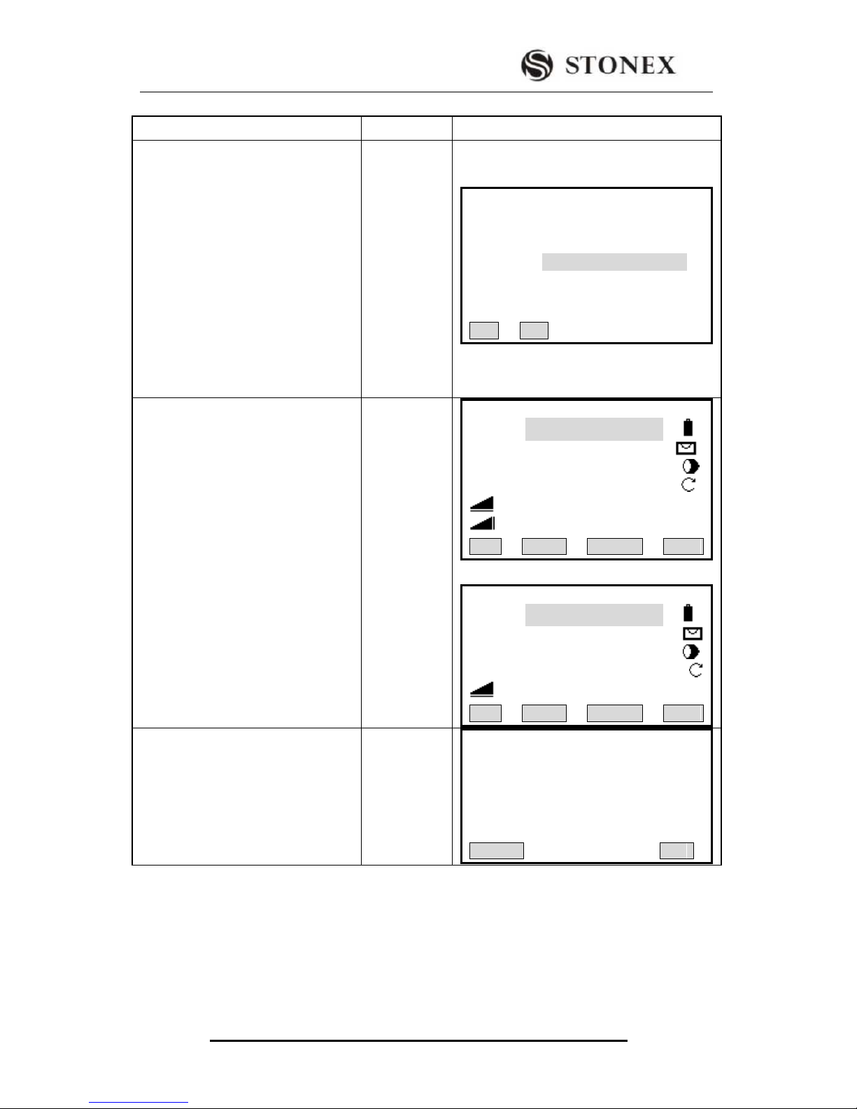
STONEX R2
72
OPERATIONAL STEPS
OPERATION
DISPLAY
① Input the first backsight PtID and
reflector height, and press [ENT]
to enter into backsight
measurement function.
Input PtID
+
[ENT]
【Known Pt】
Input BsPt!
BsPt : BS1
R. HT: 1.860 m
LIST ENH
② With Face Ⅰ, collimate on
backsight point BS1, press [F1] (All)
or [F2] (DIST) + [F3] (RECORD) to
start orientation with coordinate
measurement.
Press [PAGE] to display Page 2 of
backsight measurement.
[F1]
or
[F2]
+
[F3]
【Known Pt 】 1/2 1/ ▼
Bs Pt: BS1
R. HT: 1.860 m
HZ: 0°00′00″
V : 90°00′00″
: ﹉ .﹉ m Ⅰ
: ﹉ .﹉ m
All DIST RECORD EDM
【Known Pt 】 2/2 2/ ▼
Bs Pt: BS1
R. HT: 1.860 m
HZ: 0°00′00″
△AZ : --°--′--″
: ----.---- m Ⅰ
All DIST RECORD EDM
③ After measurement, the screen
displays “Want More Measurement?”.
Press [F4] to confirm it.
[F4]
Want More Measurement?
CANCEL OK
Page 77
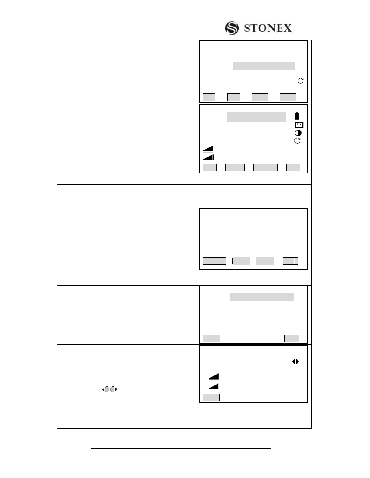
STONEX R2
73
④ In backsight orientation dialog,
input the PtID previously measured in
Face Ⅰ. Please follow Step ③ of
single point orientation.
【Known Pt 】
Input Bs Pt!
Bs Pt: BS1
R.HT: 1.254m
V : 90°00′00″
LIST ENH . .
⑤Reverse the telescope, collimate the
backsight point BS1, press [F1] (All)
OR [F2] (DIST) + [F3] (RECORD) to
start orientation with coordinate
measurement. ‴2)~ ‴3)
The upper-right corner displays “1/Ⅰ”,
indicating that first point was
measured in telescope position I
[F1]
or[F2]
+
[F3]
【Known Pt 】 1/2 1/Ⅰ ▼
Bs Pt: BS1
R. HT: 1.860 m
HZ: 0°00′00″
V : 90°00′00″
: ﹉ .﹉ m Ⅰ
: ﹉ .﹉ m
All DIST RECORD EDM
⑥After measurement, when displaying
“Want More Measurement?”,
[CANCEL]: finish measurement and
display result.
[OK]: Proceed to measure other
backsight points. Repeat steps ②~⑤
to measure the orientation of more
backsight points. The instrument
provides orientation with a maximum
of 5 backsight points.
Want More Measurement?
CANCEL OK
⑦After all points which are used for
backsight orientation are measured, in
dialog of step ⑥, press [F4](OK) to
display result.
[F4]
Orientation Result
No.Pts: 5
Station: 1
Hz Cor: 172°22′57″
St. Dev.: 0°00′20″
RESID OK
⑧ Press [F1](RESID) to enter into
Orientation Residuals dialog. Press
navigation key to view the
orientation residuals of other points.
[F1]
Orientation Residuals
BsPt: BS1
△Hz : 0°00′02″
△ : -0.005 m
△ : 0.003 m
BACK
Page 78
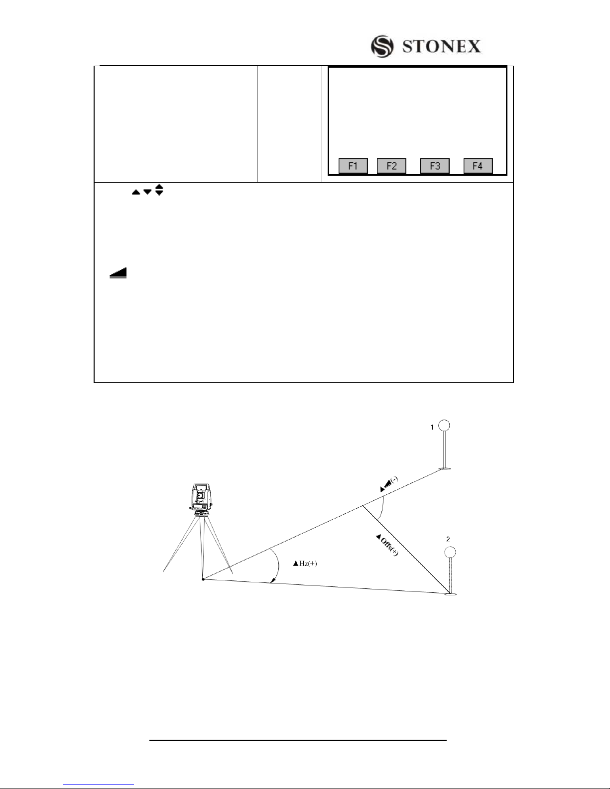
STONEX R2
74
⑨If the residuals are OK, press [F1] to
return to Orientation Result dialog.
Then press [F4] (OK) to set the
calculated HZ orientation, the screen
displays “Orientation Set Already!”,
and returns to Setting Meas menu.
[F1]
[F4]
【Setting Meas】
[*] F1 Setting Job (1)
[*] F2 Setting Station (2)
[*] F3 Set Orientation (3)
F4 Start (4)
‴ 1) , , :Implies that there are several pages selectable. Press [PAGE] to select.
‴ 2) Orientation measurement is in Page 2.
△AZ: After the first measurement, the finding of other target points (or the same point when changing
the telescope position) is easier by setting the indicated angle difference near to 0°00′0〞 by turning the
instrument.
△ :Difference between horizontal distance to target point computed from coordinates and the
measured distance.
‴ 3) If orientation measurement is based only on one face, there is no need to rotate the telescope.
Collimate on next point directly.
‴ 4) Status indication 1/I: shows that first point was measured in telescope position I.
1/II: shows that first point was measured in telescope position II.
1/I II: First point measured in telescope position I and II.
5.3.3 Displaying Residuals
In the picture, 1 is actual measurement point. 2 is design point.
Page 79
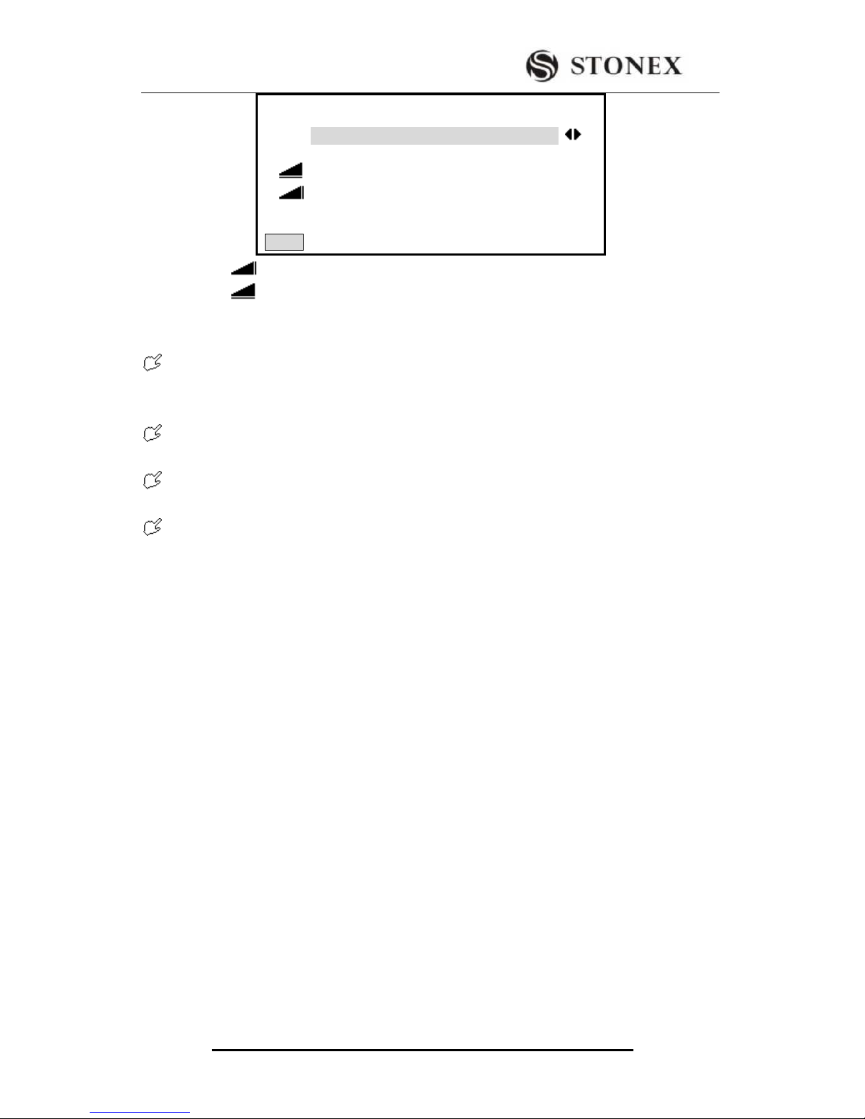
STONEX R2
75
△ : Height correction
△ : Correction of the horizontal distance
△Hz : Correction of HZ angle.
SIGNIFICANT INFORMATION
If the orientation is only measured in telescope Face II, the HZ orientation is based on
telescope Face II. If measured only in telescope Face I or mixed the HZ orientation is
based on Face I.
The prism height may not be changed during measurements in the first and second
telescope position.
If a target point is measured several times in the same telescope position, the last valid
measurement is used for the computation.
If no orientation was set and an application was started, and if in “Measure” [All] or
[REC] was triggered, then the current HZ direction and V-angle are set as orientation.
5.4 APPLICATIONS
Introduction
Applications are predefined programs that cover a wide spectrum of surveying duties and
facilities daily work in the field.
Applications listed as follow are available.
²Surveying
²Stake Out
²Free Station
²COGO
²Tie Distance
²Area (Plan)
²Remote Height
²Reference Line/Arc
²Roads
²Construction
STEPS:
Press fixed key [MENU].
Press [F1]-[F4] to select “Program” option.
Orientation Residuals
BsPt: BS1
△Hz : 0°00′02″
△ : -0.005 m
△ : 0.003 m
BACK
Page 80
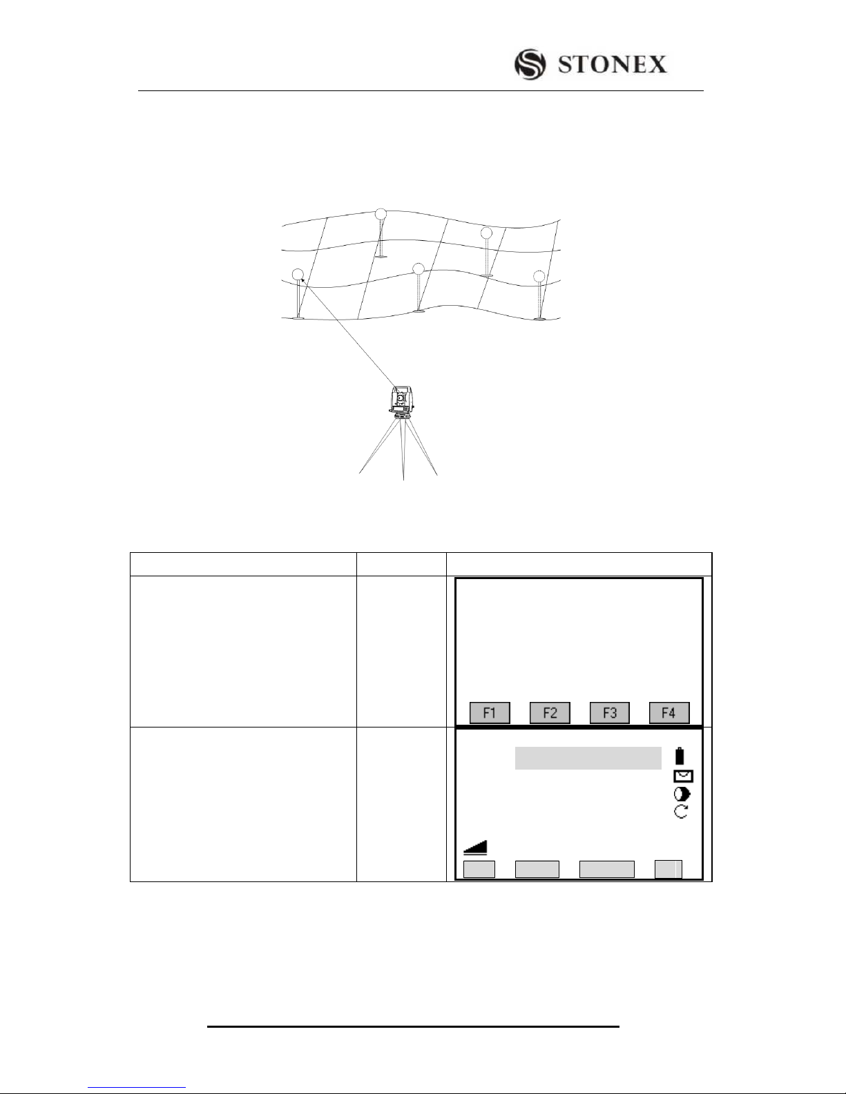
STONEX R2
76
Calling up applications and activating start programs. Press [PAGE] to turn to next page.
5.5 SURVEYING
The measurement of an unlimited number of points is supported in surveying program. It
is comparable to “Measure”, excluding stationing, orientation and coding.
OPERATION: Set job, station and orientation first!!
OPERATIONAL STEPS
OPERATION
DISPLAY
① After setting job, station and
orientation, press [F4] in Setting Meas
menu to start measurement.
[F4]
Setting Meas
[*]F1 Setting Job (1)
[*] F2 Setting Station (2)
[*] F3 Set Orientation (3)
F4 Start (4)
② Input PtID and press [ENT] to
move to next item. ‴1)
Input PtID
+
[ENT]
【Measure】 1/3
PtID: 1
R. HT: 1.860 m
Code: ------
HZ: 0°00′00″
V : 90°00′00″ Ⅰ
: ---.--- m
All DIST RECORD ↓
Page 81
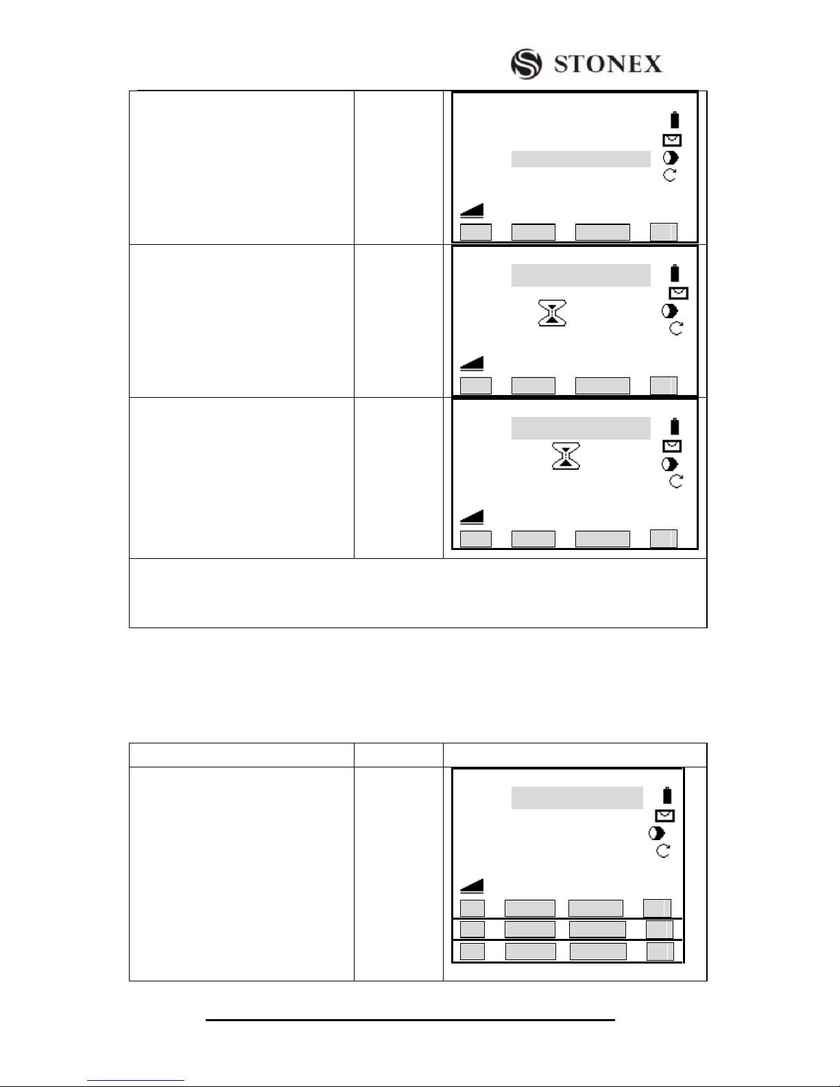
STONEX R2
77
③ Input reflector height, press [ENT]
to move to next item. Enter the code if
necessary.
Input prism
height
+
[ENT]
【Measure】 1/3
PtID: 1
R. HT: 1.860 m
Code: ------
HZ: 0°00′00″
V : 90°00′00″ Ⅰ
: ---.--- m
All DIST RECORD ↓
④ Press [F1] (All) or [F2] (DIST) +
[F3] (RECORD) to start measurement
and save the data. To see data surveyed
and saved includes angle, distance,
coordinate, press [PAGE] to view. ‴
2)
[F1]
or[F2]
+
[F3]
【Measure】 1/3
PtID: 1
R. HT: 1.860 m
Code: STONEX
HZ: 0°00′00″
V : 90°00′00″ Ⅰ
: ---.--- m
All DIST RECORD ↓
⑤ After measuring one point, PtID
will automatically +1. Press [F1] (All)
or [F2] (DIST) + [F3] (RECORD) to
proceed the measurement of next
point. Meanwhile, the screen displays
the previous measured data, and turn
[PAGE] to view.
【Measure】 1/3
PtID: 2
R. HT: 1.860 m
Code: STONEX
HZ: 85°51′31″
V : 129°20′19″ Ⅰ
: ---.--- m
All DIST RECORD ↓
‴1) Please refer to “2.7 Input Mode” to know more about the input method.
‴2)Once Surveying function is activated, all measurement data (including angle, HD, SD, VD and ENH)
will be displayed. Press [PAGE] to view.
5.5.1 Individual Point
[Indiv P]: In data collection, you can record one single point, exchanging the option
between individual point and continuous point by pressing this key.
OPERATIONAL STEPS
OPERATION
DISPLAY
① Press [F4]( ↓ ) three times to
displays the last page.
[F4]
【Measure】 1/3
PtID: 11
R. HT: 1.860 m
Code : STONEX
HZ: 0°00′00″
V : 90°00′00″ I
: ---.--- m
All DIST RECORD ↓
All CODE EDM ↓
All Q-CODE EDM ↓
Page 82
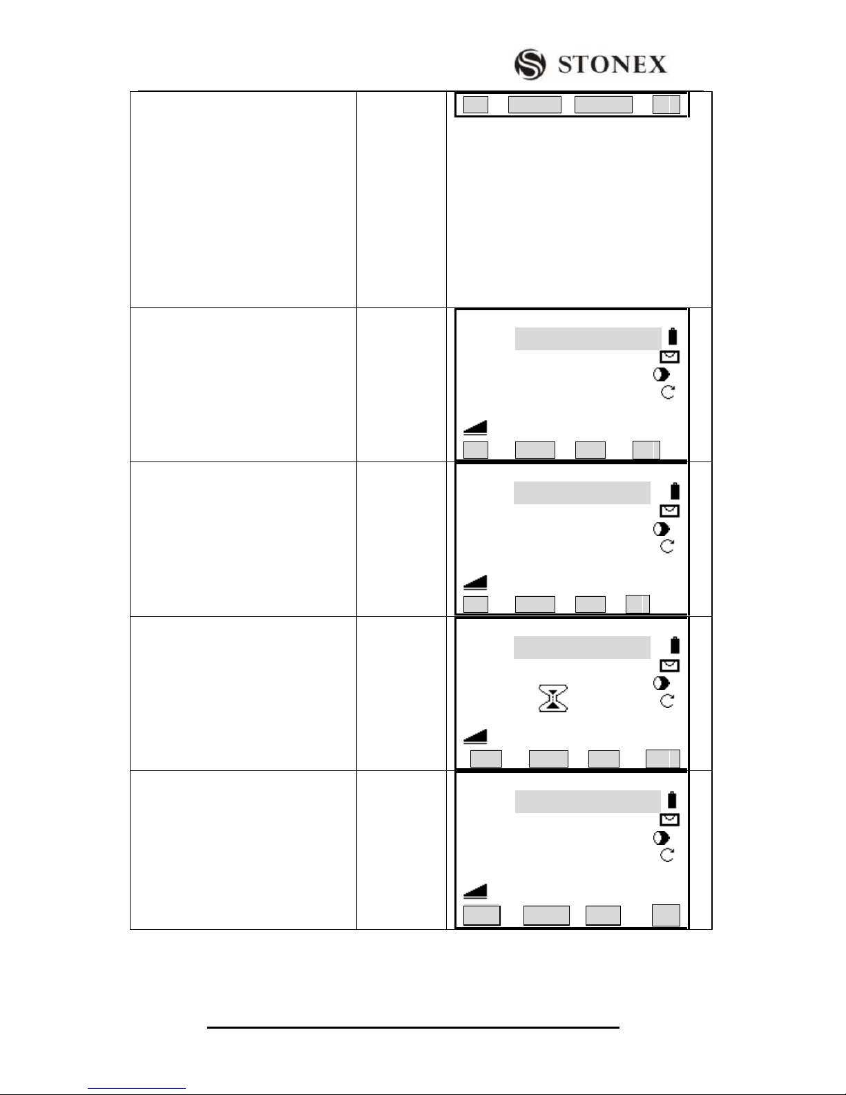
STONEX R2
78
All Indiv P EDM |←
② Press[F2] (Indiv P) to start
Individual Point function. The item of
PtID is blank. .
[F2]
【Measure】 1/3
PtID: ---------
R. HT: 1.860 m
Code : STONEX
HZ: 0°00′00″
V : 90°00′00″ I
: ---.--- m
All Indiv P EDM ↓
② Input the individual PtID, prism
height, code (if necessary). After
one item setting finished, press
[ENT] to move to next item.
Input PtID,
R.HT, Code
+
[ENT]
【Measure】 1/3
PtID: DF1
R. HT: 1.860 m
Code : STONEX
HZ: 50°30′11″
V : 96°21′26″ I
: ---.--- m
All Indiv P EDM |←
④ Press [F1] (All) or [F2] (DIST) +
[F3] (RECORD) to start measurement
and save the data measured.
[F1]
or[F2]
+
[F3]
【Measure】 1/3
PtID: DF1
R. HT: 1.860 m
Code : STONEX
HZ: 50°30′11″
V : 96°21′56″ I
: ---.--- m
All Indiv P EDM |←
⑤ As the measurement is finished, the
program will automatically deactivate
Individual Point function, and displays
the previous continuous PtID.
【Measure】 1/3
PtID: 11
R. HT: 1.860 m
Code : STONEX
HZ: 50°30′11″
V : 96°21′56″ I
: ---.--- m
All Indiv P EDM |←
Page 83
STONEX R2
79
5.5.2 Coding
Three Coding Methods are available:
1. Simple Coding:
Input a code into the relevant box. The code is stored along with the corresponding
measurement.
2. Expand Coding:
Press [CODE]. The input code is searched within the code list and it is possible to add
attributes to the code.
3. Quick Coding:
Press [Q-Code] and enter the abbr. of the code. The code is selected and the measurement
starts.
For more information, please refer to “3.3.4 Coding”.
5.6 STAKING OUT
This program calculates the required elements to stake out point coordinates or manually
entered angles, horizontal distances and heights. Stake-out differences can be displayed
continuously.
Stake Out Steps:
1. Setting job
2. Setting station
3. Setting orientation
4. Calling up coordinates from internal memory. These coordinates may be measured, or
input manually.
5. Staking out. Three methods of stake-out are available: Polar Stake Out, Orthogonal
Stake Out, and Coordinate Offset Stake Out.
5.6.1 Setting Stake-Out Point
5.6.1.1 Calling up Coordinates from job.
OPERATIONAL STEPS
OPERATION
DISPLAY
① After setting job, station and
orientation azimuth, press [F4] in
Setting Meas menu to start stake-out.
‴1)
[F4]
【Setting Meas】
[*] F1 Setting Job (1)
[*] F2 Setting Station (2)
[*] F3 Set Orientation (3)
F4 Start (4)
Page 84
STONEX R2
80
② In Find item, input the stake-out
PtID and press [ENT] to start Pt
Search function. (You can also input
wildcard “*” to start wildcard search.)
Input
stake-out
PtID
【Stake Out 】 1/3 ▼
FIND : *
PtID: 5
Type: Known
△Hz : -85°51′31″
△ : 2.055 m Ⅰ
△ : ---.--- m
All DIST RECORD ↓
③A:
The program searches PtID in the job,
and displays the result dialog. All
PtIDs will be listed separately. Press
[F4] to return to Stake Out menu.
(Input wildcard “*” to display all data
in the job.)
B
If the PtID does not exist, the program
will advise user to input the coordinate
of the point and save it. Then return to
Stake Out menu.
A:
B:
【Point Search】 1/25
A12 Known
A03 Known
12 Meas.
125 Meas.
212 Meas.
VIEW ENH JOB OK
【Pt Search】
Job : STONEX
PtID : A25
Select Job / input Pt coord.
FIND 0SET ENH
④ Press navigation key to
select the PtID to be staked out. Start
staking out.
【Stake Out 】 1/3 ▼
FIND : A*2
PtID: A25
Type: Known
△Hz : -85°51′31″
△ : 2.055 m Ⅰ
△ : ---.--- m
All DIST RECORD ↓
‴1) Methods of setting job, station and orientation have been introduced previously. Please refer to
“5.1Setting Job”, “5.2 Setting Station”, and “5.3 Set Orientation”.
Page 85
STONEX R2
81
5.6.1.2 Inputting Coordinate Manually
Press [ENH], [MANUAL] to input stake-out point manually.
Approach 1: Press [ENH] to input the coordinate of stake-out point to the job.
OPERATIONAL STEPS
OPERATION
DISPLAY
①Press [F4] (↓) to turn to Page 2.
[F4]
【Stake Out 】 1/3 ▼
FIND : *
PtID: 5
Type: Known
△Hz : -85°51′31″
△ : 2.055 m Ⅰ
△ : ---.--- m
All DIST RECORD ↓
VIEW EDM ENH ↓
② Press [F3] (ENH) to input PtID and
ENH of the stake-out point. After one
setting, press [ENT] to move to next
item.
[F3]
Input PtID &
ENH
+
[ENT]
【Coordinate Input】
Job : STONEX
PtID: ﹉﹉
X/N : --- ---.--- --- m
Y/E : --- ---.--- --- m
H/Z : --- ---.--- --- m
BACK SAVE
③ After finishing input, press [F4] to
save the data, and enter into stake-out
program. Start staking out the input
points. ‴1)
[F4]
【Stake Out 】 1/3 ▼
FIND : 5
PtID: 5
Type: Known
△Hz : -85°51′31″
△ : 2.055 m Ⅰ
△ : ---.--- m
VIEW EDM ENH ↓
‴1) Method to stake out is introduced in 5.6.2.
Page 86
STONEX R2
82
Approach 2:Press [MANUAL] to input a stake-out point without PtID or saved data.
OPERATIONAL STEPS
OPERATION
DISPLAY
①Press [F4](↓) twice to turn to Page 3.
[F4]
【Stake Out 】 1/3 ▼
FIND : *
PtID: 5
Type: Known
△Hz : -85°51′31″
△ : 2.055 m Ⅰ
△ : ---.--- m
All DIST RECORD ↓
VIEW EDM ENH ↓
B&D MANUAL LIST |←
② Press [F2] (MANUAL). Input
ENH in the dialog. After one inputting,
press [ENT] to move to next item.
Press [F2] (0SET) if you want to set
ENH to 0.
[F2]
Input ENH
+
[ENT]
Stake Out Input Data
X/N : --- ---.--- --- m
Y/E : --- ---.--- --- m
H : --- ---.--- --- m
BACK 0SET OK
③ After inputting ENH, press [F4]
(OK) to enter into Stake Out menu.
The program automatically set the
PtID to “DEFAULT”, and starts to
stake out the input points.
‴1), ‴2)
[F4]
【Stake Out 】 1/3 ▼
FIND :
PtID: DEFAULT
Type: Known
△Hz : -85°51′31″
△ : 2.055 m Ⅰ
△ : ---.--- m
B&D MANUAL |←
‴1) [MANUAL]: Data that was input will not be saved in the job.
‴2 Method to stake-out is introduced in 5.6.2.
The soft keys below the screen:
[DIST]: Starts measurement and calculation of the stake-out elements.
[RECORD]: Saves the displayed values.
Page 87
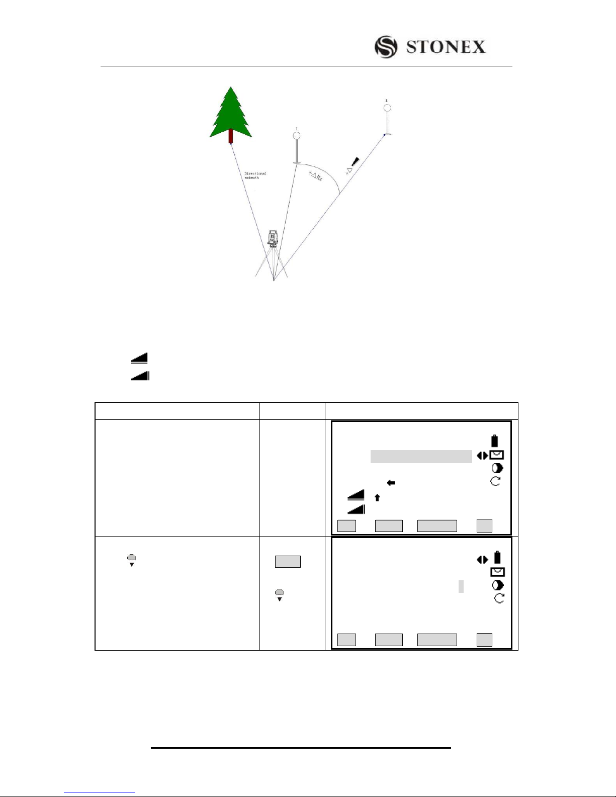
STONEX R2
83
5.6.2 Polar Stake Out
In the picture, 1: Actual 2: Point to be staked out
Normal indication of polar stake out offsets.
△Hz Angle offset: positive if point to be staked out is to the right of the actual
direction.
△ Longitudinal offset: positive if point to be staked out is further away.
△ Height offset: positive if point to be staked out is higher than measured point.
OPERATIONAL STEPS
OPERATION
DISPLAY
① Set the series of data of stake-out
point. From point list to select the
point to be staked out. You can
also call it up from the job by
inputting the stake-out PtID in Pt
Search menu.
【Stake Out 】 1/3 ▼
FIND : *
PtID: 5
Type: Known
△Hz : -85°51′31″
△ : 2.361 m Ⅰ
△ : ---.--- m
All DIST RECORD ↓
②Press [PAGE] to turn to Page 2, and
press to move to R.HT item.
Input the prism height.
PAGE
+
Input R.HT
【Stake Out 】 2/3 ▼
PtID : 5
Type: Meas.
R.HT : 2.000 m
△L Off: ---.--- m
△T Off: ---.--- m Ⅰ
△H : ---.--- m
All DIST RECORD ↓
Page 88
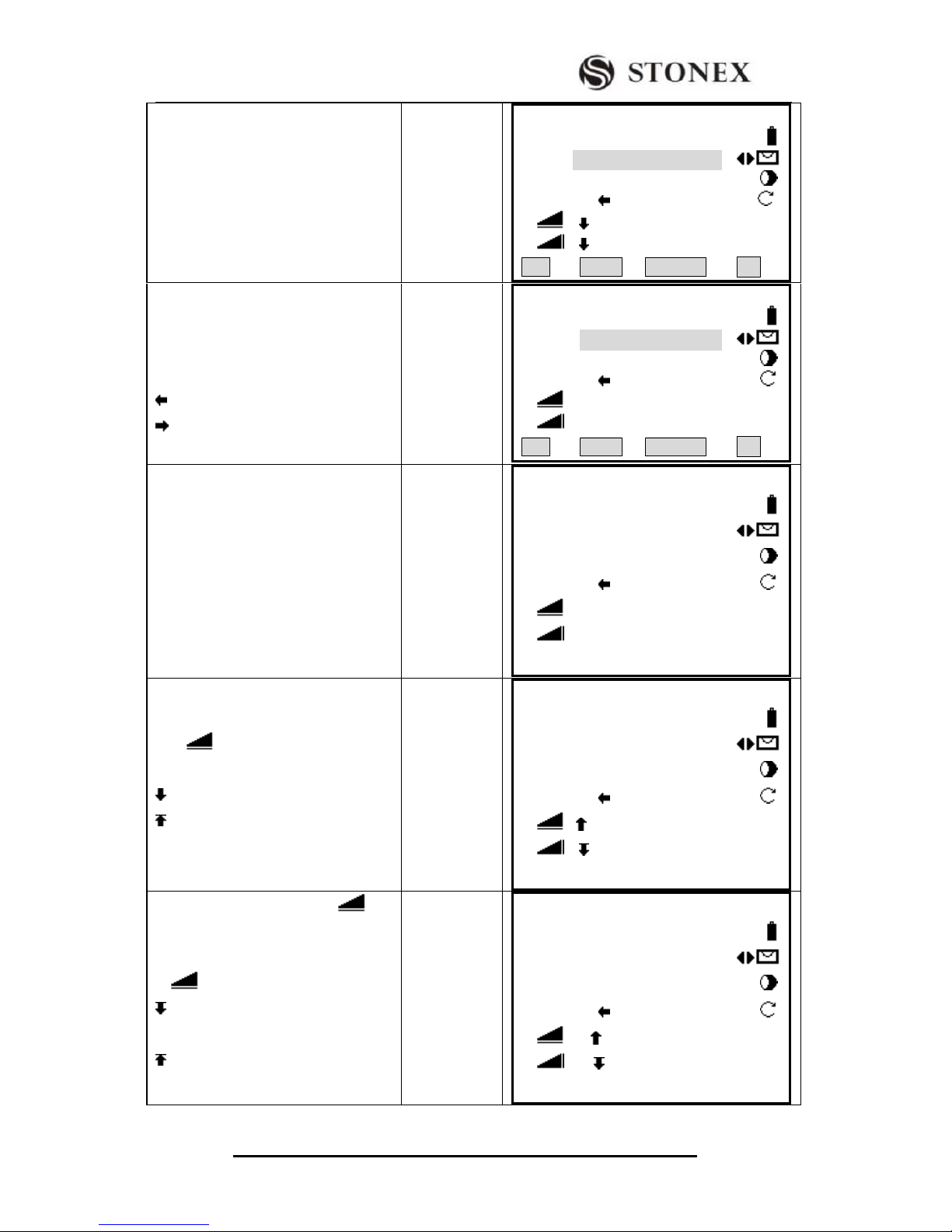
STONEX R2
84
③ Collimate the prism, press [F2]
(DIST) to start measurement and
calculate the stake-out factor offset
between measurement point and
stake-out point.
[F2]
【Stake Out 】 1/3 ▼
FIND : *
PtID: 5
Type: Known
△Hz : -85°51′31″
△ : -0.082 m Ⅰ
△ : -0.019 m
All DIST RECORD ↓
④Rotate the telescope until the angle
difference is 0°00′00″ and notify the
surveyor to move the prism.
²Arrowhead means:
:Move the prism left to the station.
:Move the prism right to the station.
【Stake Out 】 1/3 ▼
FIND : *
PtID: 5
Type: Known
△Hz : 0°00′00″
△ : 2.055 m Ⅰ
△ : -0.019 m
All DIST RECORD ↓
⑤ Set the prism at 0° direction of
telescope and collimate it. Press [F2]
(DIST) to start measurement and
calculate the stake-out factor offset
between the prism and stake-out point.
[F2]
【Stake Out 】 1/3 ▼
FIND : *
PtID: 5
Type: Known
△Hz : 0°00′00″
△ : 2.055 m Ⅰ
△ : -0 .019 m
All DIST RECORD ↓
⑥Move the prism northing or southing
according to the arrowhead until the
“△ ”displaying 0 m.
²Arrowhead means:
: Southing the prism to the station
: Northing the prism to the station.
【Stake Out 】 1/3 ▼
FIND : *
PtID: 5
Type: Known
△Hz : 0°00′00″
△ : 0.000 m Ⅰ
△ : -0 .019 m
All DIST RECORD ↓
⑦When both △ Hz and △ are
zero, it implies that the current prism
point is the stake-out point.
△ means the fill/dig data.
: To dig. The value is the depth to
dig.
:To fill. The Value is the height to
fill.
【Stake Out 】 1/3 ▼
FIND : *
PtID: 5
Type: Known
△Hz : 85°51′31″
△ : 0.000 m Ⅰ
△ : -0 .019 m
All DIST RECORD ↓
Page 89
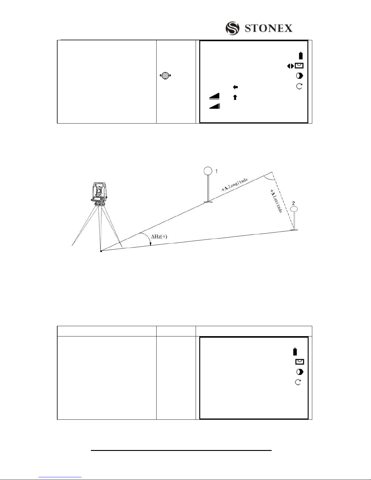
STONEX R2
85
⑧ Stake-out of point is finished.
Repeat the above press to select the
next point to be staked out. (Or call up
the existed PtID in the job via Pt
Search function.)
【Stake Out 】 1/3 ▼
FIND : *
PtID: 6
Type: Known
△Hz : 85°51′31″
△ : 2.055 m Ⅰ
△ : ---.--- m
All DIST RECORD ↓
5.6.3 Orthogonal Stake Out
The position offset between measured point and stake-out point is indicated in a longitudinal and
transversal element.
1: Actual 2: Point to be staked out
Meaning of several offsets in process of orthogonal stake-out.
△LOff Longitudinal offset: Positive if the stake-out point is further away.
△TOff Transversal offset, perpendicular to line-of-sight: Positive if the stake-out point is to the right
of measured point.
OPERATIONAL STEPS
OPERATION
DISPLY
Press [PAGE] to turn to Page 2
Orthogonal Stake Out, and select the
point to be staked out. You can also
call up the point to be staked out by
inputting the PtID in Pt Search
function in Page 1.
PAGE
【Stake Out 】 2/3 ▼
PtID : 6
Type: Meas.
R.HT : 2.000 m
△L Off: ---.--- m
△T Off: ---.--- m Ⅰ
△H : ---.--- m
All DIST RECORD ↓
Page 90
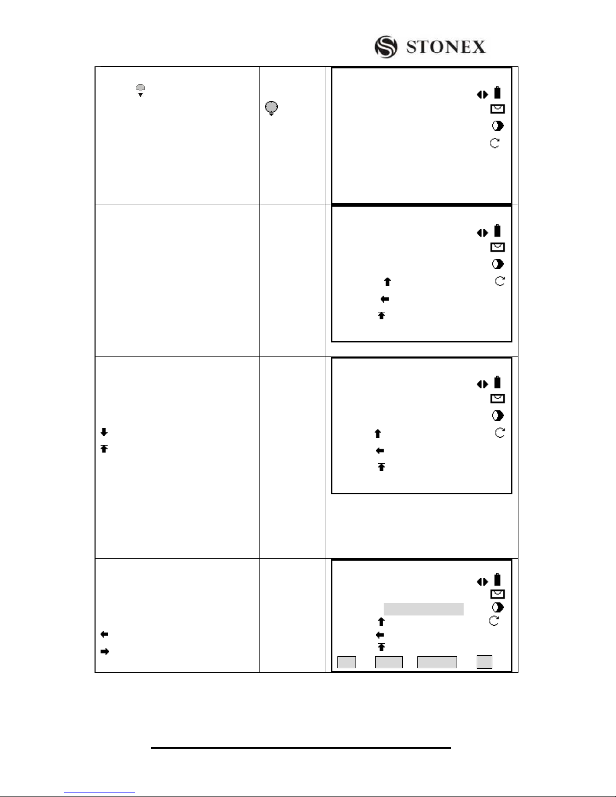
STONEX R2
86
②Press to move to R.HT item and
input the prism height.
Input prism
height
【Stake Out 】 2/3 ▼
PtID : 6
Type: Meas.
R.HT : 2.000 m
△L Off: ---.--- m
△T Off: ---.--- m Ⅰ
△H : ---.--- m
All DIST RECORD ↓
③ Collimate the current prism, press
[F2] (DIST) to start measurement and
calculate the stake-out factor offset
between the station point and stake-out
point.
The arrowhead shows the direction
move the prism.
[F2]
【Stake Out 】 2/3 ▼
PtID : 6
Type: Meas.
R.HT : 1.800 m
△L Off: 4.086 m
△T Off: -2.361m Ⅰ
△H : 1.302 m
All DIST RECORD ↓
④Move the prism northing or southing
according to the arrowhead until the
△L Off displays 0 m.
²Arrowhead means:
: Southing the prism to the station
: Northing the prism to the station.
In Stake Out program, if “Fine [r]” or
“Tracking” is selected, then the factor
difference between prism point and
stake-out point can be displayed
immediately, which is quite
convenient.
【Stake Out 】 2/3 ▼
PtID : 6
Type: Meas.
R.HT : 1.800 m
△L Off: 0.000 m
△T Off: -1.026 m Ⅰ
△H : 0.802 m
All DIST RECORD ↓
⑤Rotate the telescope until the△TOff
displays 0 m, and notify the surveyor
to move the prism.
²Arrowhead means:
:Westing the prism to the station.
:Easting the prism to the station.
【Stake Out 】 2/3 ▼
PtID : 6
Type: Meas.
R.HT : 1.800 m
△L Off: 0.000 m
△T Off: 0.000 m Ⅰ
△H : 0.822 m
All DIST RECORD ↓
Page 91
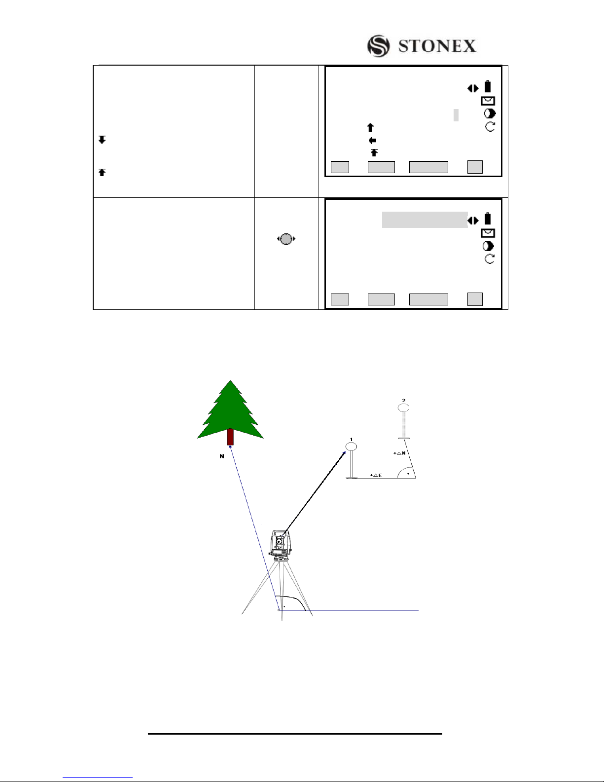
STONEX R2
87
⑥ When both △L Off and △T Off
display 0 m, it implies that the current
prism point is the stake-out point.
△ H means the fill/dig data.
: To dig. The value is the depth to
dig.
:To fill. The Value is the height to
fill.
【Stake Out 】 2/3 ▼
PtID : 6
Type: Meas.
R.HT : 2.000m
△L Off: 0 .000m
△T Off: 0 .000m Ⅰ
△H : 0.822m
All DIST RECORD ↓
⑦ Staking out of point is finished.
Continue to select the next point to
stake out. (Or call up the existed PtID
in the job via Pt Search function.)
【Stake Out 】 2/3 ▼
PtID : 7
Type: Known
R.HT : 2.000 m
△L Off: ---.--- m
△T Off: ---.--- m Ⅰ
△H : ---.--- m
All DIST RECORD ↓
5.6.4 Coordinate Offset Stake Out
Staking out is based on a coordinate system and the offset is divided into a north and
east element.
1:Actual prism position 2: Point to be staked out
Meaning of several offsets in process of coordinate stake-out.
△ X/ △ E: Offset of X coordinate between stake-out point and current
measurement point.
△ Y/ △ N: Offset of Y coordinate between stake-out point and current
Page 92
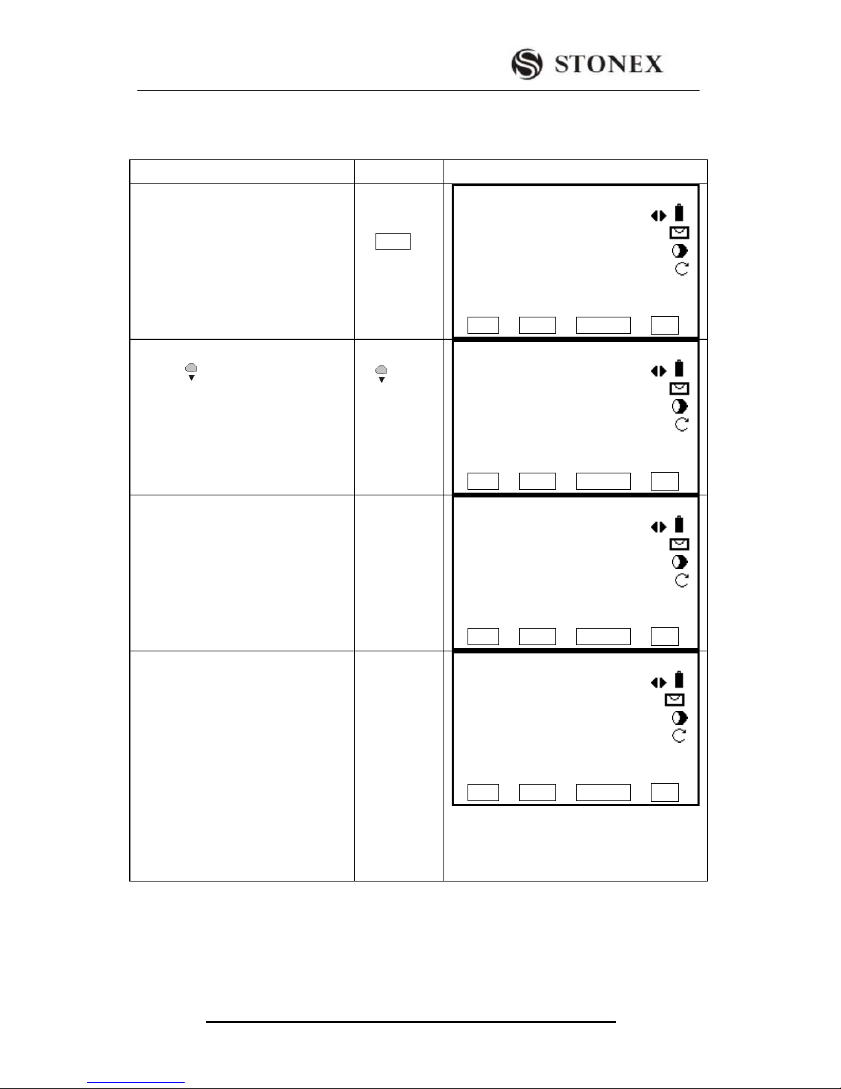
STONEX R2
88
measurement point.
OPERATIONAL STEPS
OPERATION
DISPLAY
① Press [PAGE] to turn to Page 3,
and select the point to be staked out.
You can also call up the point to be
staked out by inputting the PtID in Pt
Search function in Page 1.
PAGE
【Stake Out 】 3/3 ▼
PtID : 6
Type: Meas.
R.HT : 2.000 m
△X/N: ---.--- m
△Y/E: ---.--- m Ⅰ
△H : ---.--- m
All DIST RECORD ↓
②Press to move to R.HT item and
input the prism height.
Input prism
height
【Stake Out 】 3/3 ▼
PtID : 6
Type: Meas.
R.HT : 2.000 m
△X/N: ---.--- m
△Y/E: ---.--- m Ⅰ
△H : ---.--- m
All DIST RECORD ↓
③Collimate the prism, press [F2]
(DIST) to start measurement and
calculate the stake-out factor offset
between the station point and stake-out
point.
[F2]
【Stake Out 】 3/3 ▼
PtID : 6
Type: Meas.
R.HT : 2.000 m
△X/N: 2.785 m
△Y/E: 2.698 m Ⅰ
△H : 0.396 m
All DIST RECORD ↓
④ Northing the prism in E direction
until △Y/E displays 0 m.
When △Y/E is positive, it means the
stake-out point is on the right of
measurement point. Move the prism
rightward.
When △X/N is negative, it means the
stake-out point is on the left of
measurement point. Move the prism
leftward.
【Stake Out 】 3/3 ▼
PtID : 6
Type: Meas.
R.HT : 2.000 m
△X/N: 0.000 m
△Y/E: 2.698 m Ⅰ
△H : 0.396 m
All DIST RECORD ↓
Page 93
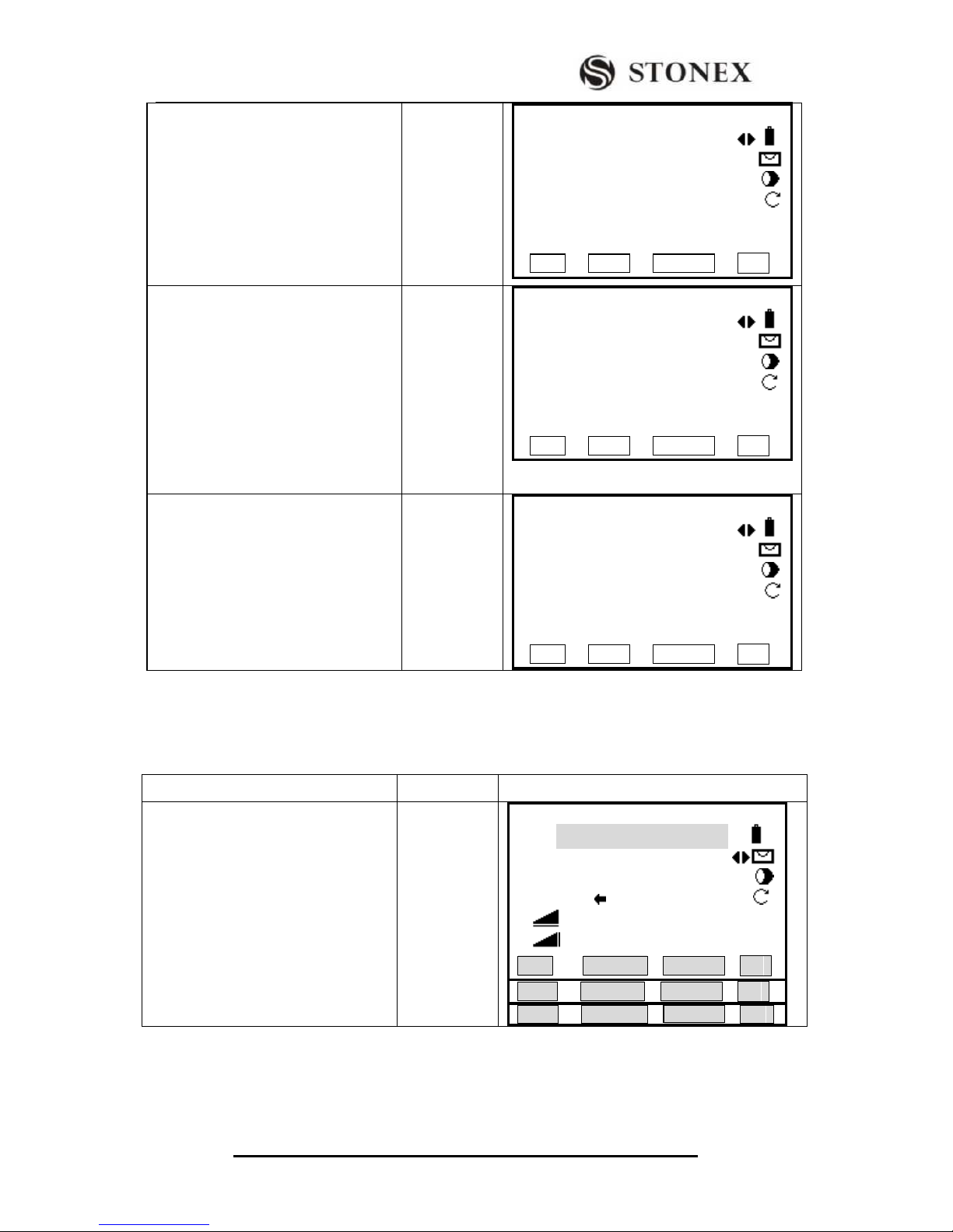
STONEX R2
89
⑤ Northing the prism on N direction
until △X/N displays 0 m.
When △X/N is positive, it means the
stake-out point is further. Move the
prism further from the station.
When △X/N is negative, move the
prism closer to station.
【Stake Out 】 3/3 ▼
PtID : 6
Type: Meas.
R.HT : 2.000 m
△X/N: 0.000 m
△Y/E: 0.000 m Ⅰ
△H : 0.396 m
All DIST RECORD ↓
⑥ When both △ Y/E and △ X/N
display 0 m, it implies that the current
prism point is the stake-out point.
△ H means the fill/dig data.
△H is positive: To fill. The value is
the height to fill.
△H is negative: To dig. The value is
the depth to dig.
【Stake Out 】 3/3 ▼
PtID : 6
Type: Meas.
R.HT : 2.000 m
△X/N: 0.000 m
△Y/E: 0.000 m Ⅰ
△H : 0.396 m
All DIST RECORD ↓
⑦ Stake-out of point is finished.
Continue to select the next point to be
staked out. (Or call up the existed PtID
in the job via Pt Search function.)
【Stake Out 】 3/3 ▼
PtID : 7
Type: Meas.
R.HT : 2.000 m
△X/N: ---.--- m
△Y/E: ---.--- m Ⅰ
△H : ---.--- m
All DIST RECORD ↓
5.6.5 B & D
Press [B&D]; input the elements of polar stake-out: azimuth and horizontal distance.
After inputting, you can start to stake out the azimuth and horizontal distance you input.
OPERATIONAL STEPS
OPERATION
DISPLAY
①Press [F4] (↓) twice to turn to Page
3 of keys.
[F4]
【Stake Out 】 1/3 ▼
Find: *
PtID: 5
Type: Known
△Hz : -85°51′31″
△ : 2.055 m Ⅰ
△ : ---.--- m
All DIST RECORD ↓
VIEW EDM ENH ↓
B&D MANUAL |←
Page 94
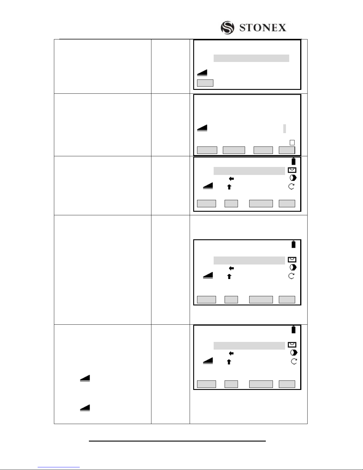
STONEX R2
90
② Press [F1] (B&D) to display as the
right dialog.
[F1]
【New Point(SideShot)】
Input TGT Pt AZ & Dist.!
PtID: --- ---
AZ: ---°---′---″
: ---.--- m
BACK
③ Input the PtID, AZ and HD of the
point to be staked out. After inputting,
press [ENT] to move to next item.
‴1)
Input PtID,
AZ, HD
+
[ENT]
【New Point(SideShot)】
Input TGT Pt AZ & Dist!
PtID: 50
AZ: 26°00′00″
: 10.000 m
01
INSERT DELETE CLEAR .
④ Collimate the prism, press [F2]
(DIST) to start measurement and
calculate the stake-out factor offset
between the station point and stake-out
point.
[F2]
【Side Shot Stake Out】
PtID: 50
△Hz : -85°51′31″
△ : 10.000 m
Ⅰ
NewPt2 DIST RECORD BACK
⑤Rotate the telescope until the △ HZ
displays 0°00′00″, and notify the
surveyor to move the prism.
When △Hz is positive, it means the
stake-out point is on the right of
measurement point. Move the prism
rightward.
When △Hz is negative, it means the
stake-out point is on the left of
measurement point. Move the prism
leftward.
【Side Shot Stake Out】
PtID: 50
△Hz : -85°51′31″
△ : 1.509 m
Ⅰ
NewPt2 DIST RECORD BACK
⑥ Set the prism on 0 direction of
telescope, press [F2] (DIST) to start
measurement and calculate the
stake-out factor offset between the
station point and stake-out point.
When △ is positive, it means the
stake-out point is further. Move the
prism further from the station.
When △ is negative, move prism
closer to station.
[F2]
【Side Shot Stake Out】
PtID: 50
△Hz : 0°00′00″
△ : 1.509 m
I
NewPt2 DIST RECORD BACK
Page 95
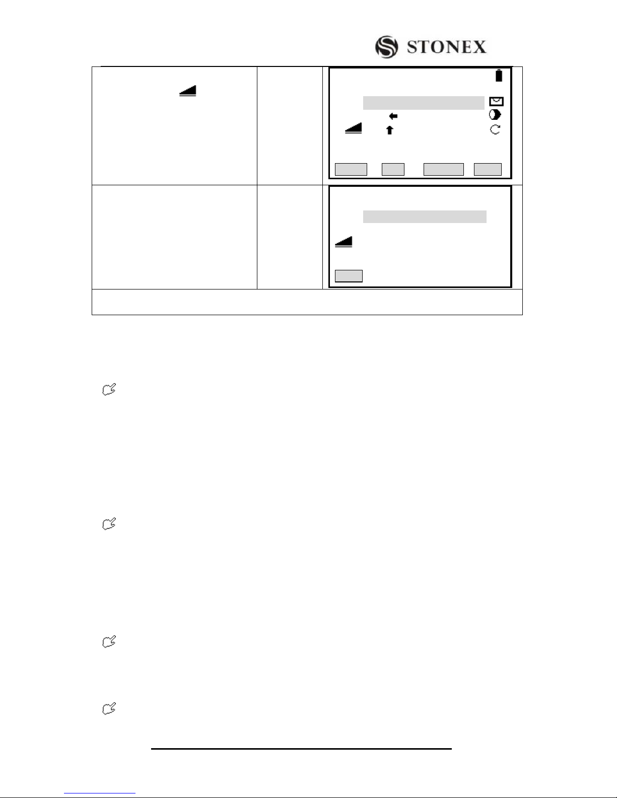
STONEX R2
91
⑦ Move the prism according to
arrowhead until“△ ” displays 0
m. If “Fine (r)” or “Tracking” is
selected to stake out, the factor offset
between prism point and stake-out
point will be displayed at real time,
which is quite convenient.‴2)
【Side Shot Stake Out】
PtID: 50
△Hz : 0°00′00″
△ : 0.000 m
Ⅰ
NewPt2 DIST RECORD BACK
⑧ After staking out one point, press
[F1] (NewPt2) and repeat Steps ②~⑦
to proceed the input and stake-out
operation of next B&D method.
【New Point (Side Shot)】
Input TGT Pt AZ & Dist.!
PtID: --- ---
AZ: ---°---′---″
: --- --- m
BACK
‴1) The data input for B&D Stake-Out will not be stored in the job.
‴2) Press [F4] (BACK) to return to Stake Out main menu.
5.7 FREE STATION
The application “Free Station” is used to determine the instrument position from
measurement to a minimum of two known points and a maximum of five known points.
The following measurements sequences to target points are possible:
HZ-angle and V-angle only
Distance and HZ-angle and V-angle
HZ-angle and V angle to some points and HZ-angle and V angle plus distance to other
points.
The final calculated results are Easting, Northing and Height of the present station,
including the instruments‟ HZ-circle orientation. Standard deviations and residuals for
accuracy assessments are provided.
Measuring Techniques:
Single face I or II measurements are always applicable.
There is no specific point sequence or specific face sequences that are required.
Gross errors checks are made for dual face measurements in order to the same point(s) are
sighted with the other face.
If a target point is measured several times in the same telescope position, the last valid
measurement is used for calculation.
Measurement Restrictions:
Status of a height of 0.000 m of the target point
If target points have a valid height of 0.000m, use 0.001 m to avoid problems in height
processing.
Computation Procedure
Page 96
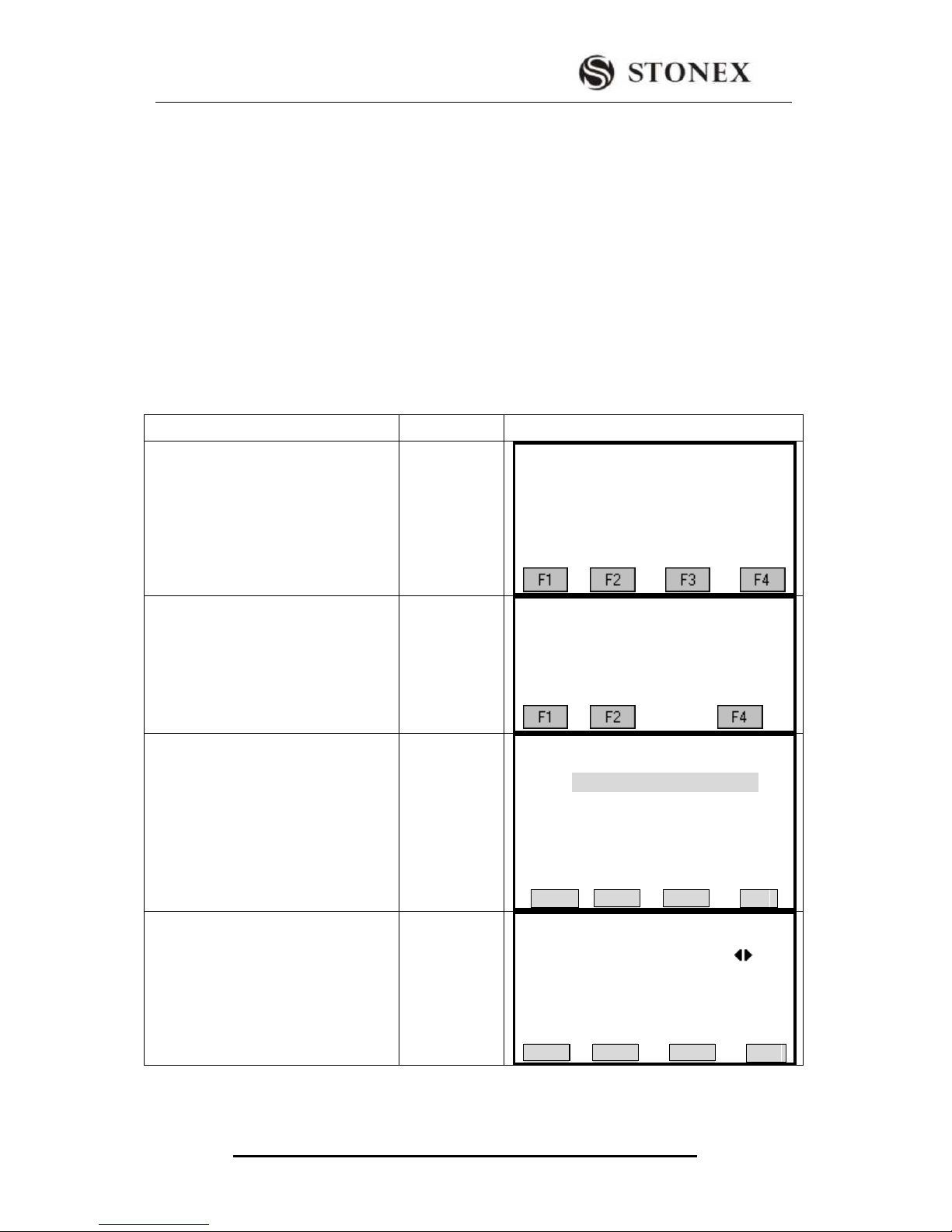
STONEX R2
92
The measuring procedure automatically determines the method of data process, e.g.
intersection, 3 point intersection, etc.
If there are more measurements, the procedure will use a least squares adjustment to
determine the plan position, heights and azimuth.
The average value of face I and face II measurements is called up to the computation
process.
Easting and northing is determined by the method of least squares, including standard
deviation and improvements for HZ-direction and horizontal distances.
The final height is computed from averaged height differences based on the original
measurement.
The HZ-circle orientation is computed by the original average face I and face II
measurements and the final computed plan position.
OPERRATIONAL STEPS
OPERATION
DISPLAY
① Press [F3] in Programs menu to
enter into Free Station function.
[F3]
【Programs】 1/3 ▼
F1 Surveying (1)
F2 Stake Out (2)
F3 Free Station (3)
F4 COGO (4)
② Press [F1] in Free Station menu to
set the job.
[F1]
【Free Station 】
[ ]F1 Setting Job (1)
[ ] F2 Setting Limit (2)
F4 Start (4)
③ Select or set up a job.
Input a job: after input the details of a
new job, and press [F4] (OK).
【Setting Job】 5/8
JOB: STONEX
Name: --- --Date: 2011.06.18
Time: 16:02:09
Note1: ----------Note2: ---------- LIST OK
④ The screen returns to Free Station
menu. Press [F2] to set limit.
[F2]
Setting Limit
Input Limit!
Status: ON
St. dev. X/N : 0.000 m
St. dev. Y/E : 0.000 m
St. dev. H/Z : 0.000 m
St. dev. Ang: 0°00′00″
SET
Page 97
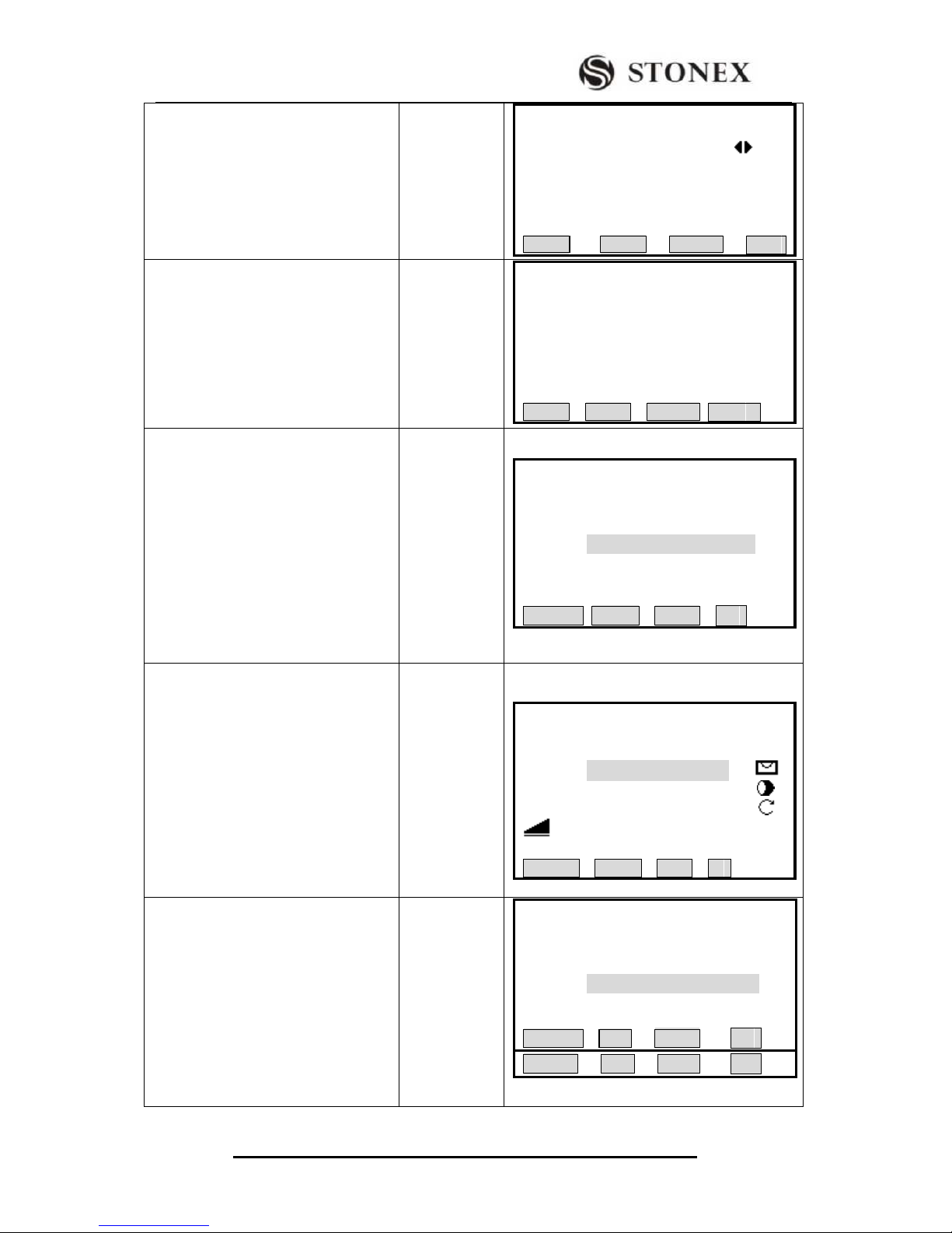
STONEX R2
93
⑤ Input the standard deviation. After
inputting one item, and press [ENT].
After inputting all deviations, press
[F4] (SET), and the screen displays
“Limit set already!” and returns to Free
Station menu.
Input standard
deviations
+
[F4]
Setting Limit
Input Limit!
Status: ON
St. dev. X/N : 0.020 m
St. dev. Y/E: 0.020 m
St. dev. H/Z : 0.010 m
St. dev. Ang: 0°00′00″
SET
⑥ Press [F4] to start free station
measurement. Set PtID and height of
the station. After one setting, press
[ENT]. After finishing inputting all
items, press [F4] (OK).
[F4]
Input station
PtID and
height
+ [ENT]
【Free Station STN Pt】
Stn.Pt: OCC1
INS. Ht: 1.500 m
O k
⑦ Set target PtID and prism height.
After inputting, press [F3] (OK). ‴1)
Input target
PtID and
R.HT
+
[F3]
【Free-Station TGT Pt 】
PtID : 2
R.HT : 2.000 m
SEARCH LIST OK ↓
⑧ Collimate target point 1 and press
[F3](DIST) to start measurement.
[F3]
【Free-Station Measure】
PtID : 2
R.HT : 2.000 m
HZ: 38°20′06″
V : 20°00′05″
: ---.--- m Ⅰ
RESULT Next Pt All ↓
⑨After finishing the measurement of
one point, press [F2] to proceed the
measurement of next point and repeat
steps ⑦, ⑧. If the measured point is
to be remeasured, press [F2] (SKIP) in
Page 2 without inputting PtID.
[F2]
【Free-Station TGT Pt】
PtID : 2
R.HT : ---.--- m
SEARCH LIST OK ↓
ENH SKIP BACK ∣←
Page 98
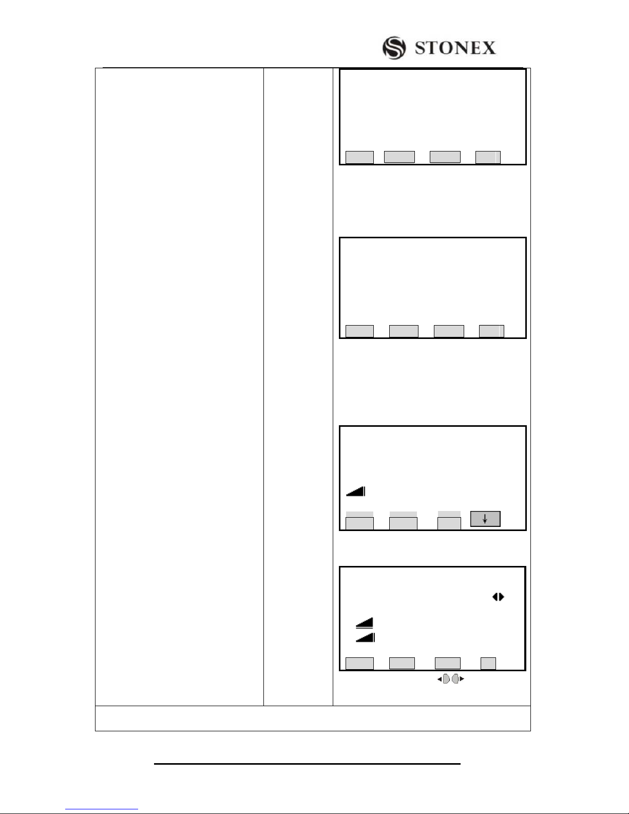
STONEX R2
94
⑩ When there are at least 2 points and
1 side are measured, the station
coordinate can be calculated and
displayed.
Press [F1] to view the result that shows
the coordinate limit between the result
and station point. Press [F4] (OK) to
display the station coordinate.
St.Dev E0,N0, H0: Standard deviation of the
station coordinates
St.DevAng : Standard deviation of the
orientation
Press[OK]:
(Press [F2] to display the residuals. Press
[F3] to display to standard deviation. Press
[F4] to set the displayed coordinates and
instrument height as new station.)
Press [BACK] to measure a known point.
Press[F2]to display the residuals:
Residual = Calculated value – Measured value
Press navigation key to view the
residual of each point.
【Limit Check】
St.DevX0 : 1.001 m
St.DevY0: 1.569 m
St.DevH0 : 10.000 m
Continue?
BACK OK
【Free-Station Result】
Stn.ID : OCC1
INS.Ht: 1.569 m
X0/N0 : 10.000 m
Y0/E0 : 10.001 m
H0 : 10.000 m
BACK RESID StdDev OK
【Free-Station Measure】 1/5
PtID: 2
R.HT: 2.000 m
HZ : 38°20′06″
V: 20°00′05″
: ---.--- m
BACK NextPt All
【Free-ST Residuals】 1/2
PtID : 2
△Hz : 0°00′01″
△ : 0.001 m
△ : 0.002 m
BACK OK
‴1) Target point can be called up from job via [SEARCH] and [LIST], and also can be input manually.
Please refer to 5.2 Setting Station for detailed instruction.
Page 99

STONEX R2
95
Warnings/Messages
Important Messages
Meaning
Selected point has no valid data!
This message occurs if the selected target point has no
easting or northing coordinate.
Max 5 points supported!
If 5 points have already been measured and another
point is selected, the system supports a maximum of 5
points.
Invalid data – no position computed!
Please repeat the Free Station
function!
The measurements may not allow final station
coordinates (Eastings, Northings) to be computed,
need to repeat measurement.
Invalid data – no height computed!
Either the target heights are invalid or insufficient
measurements are available to compute a final station
height.
Insufficient space in job!
The present selected job is full and does not allow
further storage.
More points or distances are required!
There is insufficient data measured to be able to
compute a position. Either there are not enough points
used or not enough distances measured.
5.8 COGO
“COGO”
It is an application program to perform coordinate geometry calculations such as:
²Coordinate of points
²Azimuth between points
²Distance between points
The COGO calculation methods are :
²Inverse
²Intersection
²Traverse
SOFT KEYS FUNCTIONS :
[MEAS] Jump to measurement dialog to measure the point..
[CALC] Once the datum in need is inputted, start calculating.
[STAKE] Once computation point is displayed, user can select to stake out directly.
Page 100
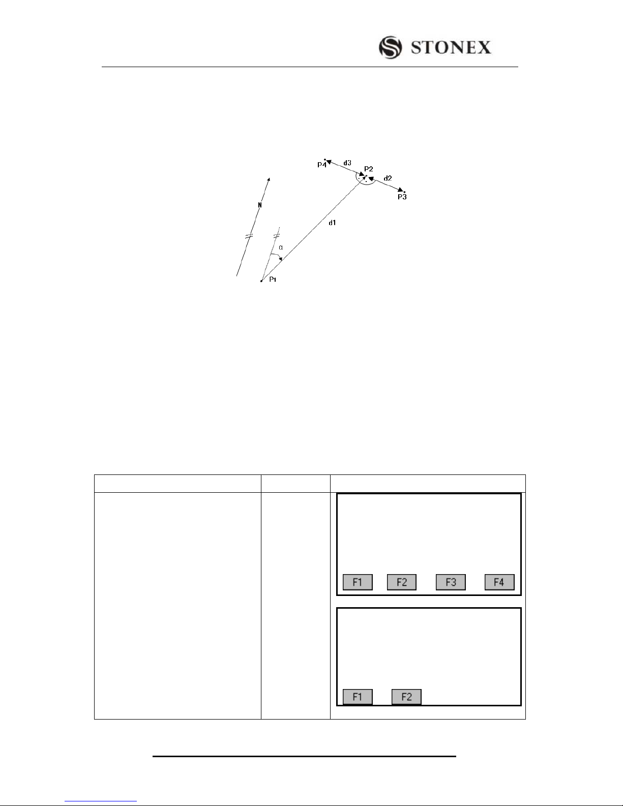
STONEX R2
96
5.8.1 Inverse & Traverse
5.8.1.1 Traverse
The known data in the graph:
P1 The known point
α Direction from P1to P2
d1 Slope distance from P1to P2
d2 offset right that is positive
d3 offset Left that is negative
The unknown datum:
P2 COGO point
P3 COGO point with positive offset
P4 COGO point with negative offset
OPERATIONAL STEPS
OPERATION
DISPLAY
① In COGO Main Menu press [F1],
and press [F1] to select Traverse
function from Inverse & Traverse
menu.
[F1]
[F1]
【COGO Main Menu】
F1 Inverse & Traverse
F2 Intersections
F3 Offset
F4 Extention
【Inverse & Traverse】
F1 Traverse
F2 Inverse
 Loading...