

Page 1

STONEGATE 5.2
FIREWALL/VPN REFERENCE GUIDE
F IREWALL
V IRTUAL PRIVATE NETWORKS
Page 2

Legal Information
End-User License Agreement
The use of the products described in these materials is subject to the then current end-user license agreement, which can be found at
the Stonesoft website:
www.stonesoft.com/en/support/eula.html
Third Party Licenses
The StoneGate software includes several open source or third-party software packages. The appropriate software licensing information for
those products at the Stonesoft website:
www.stonesoft.com/en/support/third_party_licenses.html
U.S. Government Acquisitions
If Licensee is acquiring the Software, including accompanying documentation on behalf of the U.S. Government, the following provisions
apply. If the Software is supplied to the Department of Defense (“DoD”), the Software is subject to “Restricted Rights”, as that term is
defined in the DOD Supplement to the Federal Acquisition Regulations (“DFAR”) in paragraph 252.227-7013(c) (1). If the Software is
supplied to any unit or agency of the United States Government other than DOD, the Government’s rights in the Software will be as
defined in paragraph 52.227-19(c) (2) of the Federal Acquisition Regulations (“FAR”). Use, duplication, reproduction or disclosure by the
Government is subject to such restrictions or successor provisions.
Product Export Restrictions
The products described in this document are subject to export control under the laws of Finland and the European Council Regulation (EC)
N:o 1334/2000 of 22 June 2000 setting up a Community regime for the control of exports of dual-use items and technology (as
amended). Thus, the export of this Stonesoft software in any manner is restricted and requires a license by the relevant authorities.
General Terms and Conditions of Support and Maintenance Services
The support and maintenance services for the products described in these materials are provided pursuant to the general terms for
support and maintenance services and the related service description, which can be found at the Stonesoft website:
www.stonesoft.com/en/support/view_support_offering/terms/
Replacement Service
The instructions for replacement service can be found at the Stonesoft website:
www.stonesoft.com/en/support/view_support_offering/return_material_authorization/
Hardware Warranty
The appliances described in these materials have a limited hardware warranty. The terms of the hardware warranty can be found at the
Stonesoft website:
www.stonesoft.com/en/support/view_support_offering/warranty_service/
Trademarks and Patents
The products described in these materials are protected by one or more of the following European and US patents: European Patent Nos.
1065844, 1189410, 1231538, 1259028, 1271283, 1289183, 1289202, 1304849, 1313290, 1326393, 1379046, 1330095,
131711, 1317937 and 1443729 and US Patent Nos. 6,650,621; 6 856 621; 6,885,633; 6,912,200; 6,996,573; 7,099,284;
7,127,739; 7,130,266; 7,130,305; 7,146,421; 7,162,737; 7,234,166; 7,260,843; 7,280,540; 7,302,480; 7,386,525; 7,406,534;
7,461,401; 7,721,084; and 7,739,727 and may be protected by other EU, US, or other patents, or pending applications. Stonesoft, the
Stonesoft logo and StoneGate, are all trademarks or registered trademarks of Stonesoft Corporation. All other trademarks or registered
trademarks are property of their respective owners.
Disclaimer
Although every precaution has been taken to prepare these materials, THESE MATERIALS ARE PROVIDED "AS-IS" and Stonesoft makes
no warranty to the correctness of information and assumes no responsibility for errors, omissions, or resulting damages from the use of
the information contained herein. All IP addresses in these materials were chosen at random and are used for illustrative purposes only.
Copyright © 2010 Stonesoft Corporation. All rights reserved. All specifications are subject to change.
Revision: SGFRG_20101015
2
Page 3

TABLE OF CONTENTS
INTRODUCTION
CHAPTER 1
Using StoneGate Documentation . . . . . . . . . . . 13
How to Use This Guide . . . . . . . . . . . . . . . . . . 14
Typographical Conventions . . . . . . . . . . . . . . 14
Documentation Available. . . . . . . . . . . . . . . . . 15
Product Documentation. . . . . . . . . . . . . . . . . 15
Support Documentation . . . . . . . . . . . . . . . . 15
System Requirements. . . . . . . . . . . . . . . . . . 16
Contact Information . . . . . . . . . . . . . . . . . . . . 16
Licensing Issues . . . . . . . . . . . . . . . . . . . . . 16
Technical Support. . . . . . . . . . . . . . . . . . . . . 16
Your Comments . . . . . . . . . . . . . . . . . . . . . . 16
Other Queries. . . . . . . . . . . . . . . . . . . . . . . . 16
CHAPTER 2
Introduction to Firewalls . . . . . . . . . . . . . . . . . 17
The Role of the Firewall. . . . . . . . . . . . . . . . . . 18
Firewall Technologies . . . . . . . . . . . . . . . . . . . 18
Packet Filtering. . . . . . . . . . . . . . . . . . . . . . . 18
Proxy Firewalls . . . . . . . . . . . . . . . . . . . . . . . 19
Stateful Inspection . . . . . . . . . . . . . . . . . . . . 19
StoneGate Multi-Layer Inspection. . . . . . . . . . 19
Additional Firewall Features . . . . . . . . . . . . . . . 21
Authentication . . . . . . . . . . . . . . . . . . . . . . . 21
Deep Packet Inspection and Unified Threat
Management . . . . . . . . . . . . . . . . . . . . . . . . 21
Integration With External Content Inspection. . 21
Load Balancing and Traffic Management. . . . . 22
Logging and Reporting . . . . . . . . . . . . . . . . . 22
Network Address Translation (NAT). . . . . . . . . 23
VPNs . . . . . . . . . . . . . . . . . . . . . . . . . . . . . . 23
Firewall Weaknesses. . . . . . . . . . . . . . . . . . . . 23
Complexity of Administration . . . . . . . . . . . . . 23
Single Point of Failure . . . . . . . . . . . . . . . . . . 24
Worms, Viruses, and Targeted Attacks . . . . . . 24
CHAPTER 3
Introduction to StoneGate
Firewall/VPN . . . . . . . . . . . . . . . . . . . . . . . . . . 25
The StoneGate Security Platform . . . . . . . . . . . 26
StoneGate Firewall/VPN System Components. . 27
Firewall/VPN Engines . . . . . . . . . . . . . . . . . . 28
Main Benefits of StoneGate Firewall/VPN. . . . . 28
Advanced Traffic Inspection. . . . . . . . . . . . . . 28
Built-in Clustering for Load Balancing and
High Availability . . . . . . . . . . . . . . . . . . . . . . 29
Multi-Link Technology . . . . . . . . . . . . . . . . . . 29
Built-in Inbound Traffic Management . . . . . . . 30
QoS and Bandwidth Management . . . . . . . . . 30
Integration with StoneGate IPS . . . . . . . . . . . 31
Clustered Multi-Link VPNs. . . . . . . . . . . . . . . 31
CHAPTER 4
StoneGate Firewall/VPN Deployment . . . . . . . . 33
Deployment Overview . . . . . . . . . . . . . . . . . . . 34
Supported Platforms . . . . . . . . . . . . . . . . . . 34
General Deployment Guidelines . . . . . . . . . . 34
Positioning Firewalls. . . . . . . . . . . . . . . . . . . . 35
External to Internal Network Boundary. . . . . . 35
Internal Network Boundaries. . . . . . . . . . . . . 36
DMZ Network Boundaries . . . . . . . . . . . . . . . 37
Positioning Management Center Components . 38
INTERFACES AND ROUTING
CHAPTER 5
Single Firewall Configuration. . . . . . . . . . . . . . 41
Overview to Single Firewall Configuration . . . . . 42
Configuration of Single Firewalls . . . . . . . . . . . 42
Dynamic Firewall Interface Addresses . . . . . . 42
Internal DHCP Server . . . . . . . . . . . . . . . . . . 43
Configuration Workflow. . . . . . . . . . . . . . . . . 43
Task 1: Create a Single Firewall
Element . . . . . . . . . . . . . . . . . . . . . . . . . . 43
Task 2: Define Physical Interfaces . . . . . . . 43
Task 3: Define VLAN Interfaces. . . . . . . . . . 43
Task 4: Define an ADSL Interface . . . . . . . . 44
Task 5: Define IP Addresses. . . . . . . . . . . . 44
Task 6: Define Modem Interfaces . . . . . . . . 44
Task 7: Install the Firewall Engine . . . . . . . . 44
Task 8: Install a Firewall Policy . . . . . . . . . . 45
Example of a Single Firewall Deployment . . . . . 45
Setting up a Single Firewall. . . . . . . . . . . . . . 45
Adding a New Interface to an Existing
Configuration. . . . . . . . . . . . . . . . . . . . . . . . 46
Table of Contents
3
Page 4

CHAPTER 6
Firewall Cluster Configuration . . . . . . . . . . . . . 47
Overview to Firewall Cluster Configuration. . . . . 48
Benefits of Clustering . . . . . . . . . . . . . . . . . . 48
Communication Between the Nodes. . . . . . . . 48
Hardware . . . . . . . . . . . . . . . . . . . . . . . . . . . 49
Configuration of Firewall Clusters. . . . . . . . . . . 49
Load Balancing. . . . . . . . . . . . . . . . . . . . . . . 49
Standby Operation . . . . . . . . . . . . . . . . . . . . 49
Network Interfaces and IP Addresses. . . . . . . 50
Clustering Modes . . . . . . . . . . . . . . . . . . . . . 51
How Packet Dispatch Works . . . . . . . . . . . . . 51
Configuration Workflow . . . . . . . . . . . . . . . . . 53
Task 1: Create a Firewall Cluster
Element. . . . . . . . . . . . . . . . . . . . . . . . . . . 53
Task 2: Create Physical Interfaces. . . . . . . . 53
Task 3: Define VLAN Interfaces . . . . . . . . . . 53
Task 4: Configure Physical or VLAN
Interfaces . . . . . . . . . . . . . . . . . . . . . . . . . 54
Task 5: Install the Firewall Engines . . . . . . . 55
Task 6: Install a Firewall Policy . . . . . . . . . . 55
Using a Firewall Cluster. . . . . . . . . . . . . . . . . . 55
Internal DHCP Server . . . . . . . . . . . . . . . . . . 55
Node State Synchronization. . . . . . . . . . . . . . 56
Security Level for State Synchronization . . . . . 56
Manual Load Balancing. . . . . . . . . . . . . . . . . 56
Examples of Firewall Cluster Deployment . . . . . 57
Setting up a Firewall Cluster . . . . . . . . . . . . . 57
Adding a Node to a Firewall Cluster . . . . . . . . 58
CHAPTER 7
Routing and Antispoofing. . . . . . . . . . . . . . . . . 59
Overview to Routing and Antispoofing. . . . . . . . 60
Configuration of Routing and Antispoofing . . . . 60
Reading the Routing and Antispoofing Trees . . 60
Multi-Link Routing for Single and Clustered
Firewalls . . . . . . . . . . . . . . . . . . . . . . . . . . . 62
Default Elements . . . . . . . . . . . . . . . . . . . . . 62
Configuration Workflow . . . . . . . . . . . . . . . . . 63
Task 1: Add Router or NetLink. . . . . . . . . . . 63
Task 2: Add Network(s). . . . . . . . . . . . . . . . 63
Task 3: Refresh Firewall Policy . . . . . . . . . . 63
Using Routing and Antispoofing . . . . . . . . . . . . 63
Policy Routing. . . . . . . . . . . . . . . . . . . . . . . . 63
Multicast Routing . . . . . . . . . . . . . . . . . . . . . 63
Modifying Antispoofing . . . . . . . . . . . . . . . . . 64
Examples of Routing . . . . . . . . . . . . . . . . . . . . 64
Routing Traffic with Two Interfaces . . . . . . . . . 64
Routing Internet Traffic with Multi-Link . . . . . . 64
Routing Traffic to Networks That Use Same
Address Space . . . . . . . . . . . . . . . . . . . . . . 65
ACCESS CONTROL POLICIES
CHAPTER 8
Firewall Policies . . . . . . . . . . . . . . . . . . . . . . . 69
Overview to Firewall Policies . . . . . . . . . . . . . . 70
Policy Hierarchy . . . . . . . . . . . . . . . . . . . . . . 70
How StoneGate Examines the Packets. . . . . . 70
Configuration of Policy Elements . . . . . . . . . . . 72
Default Elements . . . . . . . . . . . . . . . . . . . . . 74
Configuration Workflow. . . . . . . . . . . . . . . . . 74
Task 1: Create a Firewall Template
Policy . . . . . . . . . . . . . . . . . . . . . . . . . . . . 74
Task 2: Create a Firewall Policy. . . . . . . . . . 75
Task 3: Create a Firewall Sub-Policy . . . . . . 75
Task 4: Install the Policy . . . . . . . . . . . . . . 76
Using Policy Elements and Rules. . . . . . . . . . . 77
Validating Policies . . . . . . . . . . . . . . . . . . . . 77
Connection Tracking vs. Connectionless Packet
Inspection . . . . . . . . . . . . . . . . . . . . . . . . . . 77
Policy Snapshots . . . . . . . . . . . . . . . . . . . . . 80
Continue Rules . . . . . . . . . . . . . . . . . . . . . . 80
Adding Comments to Rules. . . . . . . . . . . . . . 80
Examples of Policy Element Use . . . . . . . . . . . 81
Protecting Essential Communications . . . . . . 81
Improving Readability and Performance . . . . . 81
Restricting Administrator Editing Rights . . . . . 82
CHAPTER 9
Access Rules . . . . . . . . . . . . . . . . . . . . . . . . . . 83
Overview to Access Rules . . . . . . . . . . . . . . . . 84
Configuration of Access Rules. . . . . . . . . . . . . 85
Considerations for Designing Access Rules . . 87
Default Elements . . . . . . . . . . . . . . . . . . . . . 87
Configuration Workflow. . . . . . . . . . . . . . . . . 89
Task 1: Define the Source and
Destination . . . . . . . . . . . . . . . . . . . . . . . . 89
Task 2: Define the Service . . . . . . . . . . . . . 89
Task 3: Select the Action and Action
Options. . . . . . . . . . . . . . . . . . . . . . . . . . . 90
Task 4: Select Logging Options. . . . . . . . . . 92
Task 5: Add User Authentication . . . . . . . . . 92
Task 6: Restrict the Time When the
Rule Is Enforced . . . . . . . . . . . . . . . . . . . . 92
Task 7: Restrict the Rule Match Based
on Source VPN . . . . . . . . . . . . . . . . . . . . . 93
4
Table of Contents
Page 5

Using Access Rules . . . . . . . . . . . . . . . . . . . . 93
Allowing System Communications . . . . . . . . . 93
Configuring Default Settings for Several Rules 94
Using Continue Rules to Set Logging
Options . . . . . . . . . . . . . . . . . . . . . . . . . . . 94
Using Continue Rules to set the
Protocol. . . . . . . . . . . . . . . . . . . . . . . . . . . 95
Using Aliases in Access Rules. . . . . . . . . . . . 95
Examples of Access Rules. . . . . . . . . . . . . . . . 96
Example of Rule Order . . . . . . . . . . . . . . . . . 96
Example of Continue Rules . . . . . . . . . . . . . . 98
CHAPTER 10
Inspection Rules . . . . . . . . . . . . . . . . . . . . . . . 99
Overview to Inspection Rules. . . . . . . . . . . . . . 100
Configuration of Inspection Rules. . . . . . . . . . . 101
Considerations for Designing Inspection Rules 102
Exception Rule Cells . . . . . . . . . . . . . . . . . . . 103
Default Elements . . . . . . . . . . . . . . . . . . . . . 104
Configuration Workflow . . . . . . . . . . . . . . . . . 104
Task 1: Activate Deep Inspection in
Access Rules . . . . . . . . . . . . . . . . . . . . . . . 105
Task 2: Activate the Relevant Inspection
Checks . . . . . . . . . . . . . . . . . . . . . . . . . . . 105
Task 3: Define the Exceptions . . . . . . . . . . . 105
Task 4: Eliminate False Positives. . . . . . . . . 106
Task 5: Add Custom Inspection Checks . . . . 106
Using Inspection Rules . . . . . . . . . . . . . . . . . . 106
Setting Default Options for Several Inspection
Rules. . . . . . . . . . . . . . . . . . . . . . . . . . . . . . 106
Example of Inspection Rules . . . . . . . . . . . . . . 107
Eliminating a False Positive . . . . . . . . . . . . . . 107
CHAPTER 11
Network Address Translation (NAT) Rules . . . . 109
Overview to NAT . . . . . . . . . . . . . . . . . . . . . . . 110
Static Source Translation . . . . . . . . . . . . . . . 110
Dynamic Source Translation . . . . . . . . . . . . . 111
Static Destination Translation . . . . . . . . . . . . 112
Destination Port Translation . . . . . . . . . . . . . 112
Configuration of NAT . . . . . . . . . . . . . . . . . . . . 113
Considerations for Designing NAT Rules . . . . . 115
Default Elements . . . . . . . . . . . . . . . . . . . . . 115
Configuration Workflow . . . . . . . . . . . . . . . . . 115
Task 1: Define Source, Destination, and
Service . . . . . . . . . . . . . . . . . . . . . . . . . . . 115
Task 2: Define Address Translation . . . . . . . 115
Task 3: Define the Firewall(s) that Apply
the Rule. . . . . . . . . . . . . . . . . . . . . . . . . . . 116
Task 4: Check Other Configurations. . . . . . . 116
Using NAT and NAT Rules . . . . . . . . . . . . . . . . 116
NAT and System Communications . . . . . . . . . 116
Example of a Situation Where a
Contact Address is Needed . . . . . . . . . . . . 117
Contact Addresses and Locations . . . . . . . . 118
Outbound Load Balancing NAT . . . . . . . . . . . 118
Proxy ARP and NAT. . . . . . . . . . . . . . . . . . . . 119
Protocols and NAT . . . . . . . . . . . . . . . . . . . . 119
Examples of NAT . . . . . . . . . . . . . . . . . . . . . . 119
Dynamic Source Address Translation . . . . . . . 119
Static Address Translation . . . . . . . . . . . . . . 120
NAT with Hosts in the Same Network. . . . . . . 120
CHAPTER 12
Protocol Agents . . . . . . . . . . . . . . . . . . . . . . . 123
Overview to Protocol Agents . . . . . . . . . . . . . . 124
Connection Handling . . . . . . . . . . . . . . . . . . 124
Protocol Validation . . . . . . . . . . . . . . . . . . . . 124
NAT in Application Data . . . . . . . . . . . . . . . . 125
Configuration of Protocol Agents . . . . . . . . . . . 125
Configuration Workflow. . . . . . . . . . . . . . . . . 125
Task 1: Create a Custom Service with
a Protocol Agent . . . . . . . . . . . . . . . . . . . . 125
Task 2: Set Parameters for the Protocol
Agent . . . . . . . . . . . . . . . . . . . . . . . . . . . . 126
Task 3: Insert the Service in Access
Rules . . . . . . . . . . . . . . . . . . . . . . . . . . . . 126
Using Protocol Agents . . . . . . . . . . . . . . . . . . 126
FTP Agent . . . . . . . . . . . . . . . . . . . . . . . . . . 126
H.323 Agent . . . . . . . . . . . . . . . . . . . . . . . . 127
HTTP Agents . . . . . . . . . . . . . . . . . . . . . . . . 127
HTTPS Agent . . . . . . . . . . . . . . . . . . . . . . . . 127
ICMP Agent . . . . . . . . . . . . . . . . . . . . . . . . . 128
MSRPC Agent . . . . . . . . . . . . . . . . . . . . . . . 128
NetBIOS Agent. . . . . . . . . . . . . . . . . . . . . . . 128
Oracle Agent . . . . . . . . . . . . . . . . . . . . . . . . 128
Remote Shell (RSH) Agent . . . . . . . . . . . . . . 128
Services in Firewall Agent . . . . . . . . . . . . . . . 129
SIP Agent . . . . . . . . . . . . . . . . . . . . . . . . . . 129
SMTP Agent. . . . . . . . . . . . . . . . . . . . . . . . . 129
SSH Agent. . . . . . . . . . . . . . . . . . . . . . . . . . 129
SunRPC Agent . . . . . . . . . . . . . . . . . . . . . . . 129
TCP Proxy Agent. . . . . . . . . . . . . . . . . . . . . . 130
TFTP Agent . . . . . . . . . . . . . . . . . . . . . . . . . 130
Examples of Protocol Agent Use . . . . . . . . . . . 130
Preventing Active Mode FTP . . . . . . . . . . . . . 130
Logging URLs Accessed by Internal Users . . . 131
Table of Contents
5
Page 6

CHAPTER 13
User Authentication . . . . . . . . . . . . . . . . . . . . . 133
Overview to User Authentication . . . . . . . . . . . 134
Configuration of User Authentication . . . . . . . . 135
The Internal User Database. . . . . . . . . . . . . . 136
External User Database Integration . . . . . . . . 137
External User Database Without Integration . . 137
User Management . . . . . . . . . . . . . . . . . . . . 137
Authentication Services . . . . . . . . . . . . . . . . 138
RADIUS Authentication . . . . . . . . . . . . . . . . 138
TACACS+ Authentication . . . . . . . . . . . . . . . 138
Default Elements . . . . . . . . . . . . . . . . . . . . . 138
Configuration Workflow . . . . . . . . . . . . . . . . . 139
Task 1: Create an External Authentication
Server Element. . . . . . . . . . . . . . . . . . . . . . 139
Task 2: Create an LDAP Server Element. . . . 139
Task 3: Create an Authentication Service
Element. . . . . . . . . . . . . . . . . . . . . . . . . . . 139
Task 4: Add an LDAP Domain . . . . . . . . . . . 140
Task 5: Add Users and User Groups . . . . . . 140
Task 6: Define User Authentication in
IPv4 Access Rules . . . . . . . . . . . . . . . . . . . 141
Examples of User Authentication . . . . . . . . . . . 143
Using the Internal Database for Authenticating
Users . . . . . . . . . . . . . . . . . . . . . . . . . . . . . 143
Using StoneGate with a Microsoft Active
Directory Server . . . . . . . . . . . . . . . . . . . . . . 143
Using SecurID Authentication with StoneGate
VPN Clients . . . . . . . . . . . . . . . . . . . . . . . . . 144
CHAPTER 14
HTTPS Inspection . . . . . . . . . . . . . . . . . . . . . . 147
Overview to HTTPS Inspection . . . . . . . . . . . . . 148
Configuration of HTTPS Inspection . . . . . . . . . . 149
Default Elements . . . . . . . . . . . . . . . . . . . . . 149
Configuration Workflow . . . . . . . . . . . . . . . . . 149
Task 1: Create Server Protection
Credentials Elements . . . . . . . . . . . . . . . . . 149
Task 2: Create Client Protection
Certificate Authority Elements . . . . . . . . . . . 150
Task 3: Specify HTTPS Inspection
Options in the Firewall Properties. . . . . . . . . 150
Task 4: Create an HTTPS Inspection
Exceptions Element . . . . . . . . . . . . . . . . . . 150
Task 5: Create a Custom HTTPS
Service . . . . . . . . . . . . . . . . . . . . . . . . . . . 150
Task 6: Create an IPv4 Access Rule. . . . . . . 150
Using HTTPS Inspection . . . . . . . . . . . . . . . . . 151
Security Considerations . . . . . . . . . . . . . . . . 151
Virus Scanning of Decrypted HTTPS Traffic . . . 151
Examples of HTTPS Inspection. . . . . . . . . . . . . 151
Server Protection . . . . . . . . . . . . . . . . . . . . . 151
Client Protection . . . . . . . . . . . . . . . . . . . . . 152
CHAPTER 15
Web Filtering . . . . . . . . . . . . . . . . . . . . . . . . . 153
Overview to Web Filtering . . . . . . . . . . . . . . . . 154
Configuration of Web Filtering . . . . . . . . . . . . . 154
Default Elements . . . . . . . . . . . . . . . . . . . . . 155
Configuration Workflow. . . . . . . . . . . . . . . . . 155
Task 1: Prepare the Firewall . . . . . . . . . . . . 155
Task 2: Create User Response Messages . . 155
Task 3: Blacklist/Whitelist Individual URLs . 155
Task 4: Configure Web Filtering Rules
in the Policy. . . . . . . . . . . . . . . . . . . . . . . . 155
Examples of Web Filtering. . . . . . . . . . . . . . . . 156
Allowing a Blocked URL . . . . . . . . . . . . . . . . 156
CHAPTER 16
Virus Scanning . . . . . . . . . . . . . . . . . . . . . . . . 157
Overview to Virus Scanning. . . . . . . . . . . . . . . 158
Configuration of Virus Scanning . . . . . . . . . . . 158
Configuration Workflow. . . . . . . . . . . . . . . . . 158
Task 1: Activate the Anti-Virus Feature
for a Firewall . . . . . . . . . . . . . . . . . . . . . . . 158
Task 2: Select Traffic for Inspection
with Access Rules . . . . . . . . . . . . . . . . . . . 158
Task 3: Define the Content Not to Be
Scanned . . . . . . . . . . . . . . . . . . . . . . . . . . 159
Using Virus Scanning . . . . . . . . . . . . . . . . . . . 159
Integrated Scanning vs. Content Inspection
Server. . . . . . . . . . . . . . . . . . . . . . . . . . . . . 159
Limitations of Virus Scanning on Clusters . . . 159
CHAPTER 17
External Content Inspection . . . . . . . . . . . . . . 161
Overview to Content Inspection . . . . . . . . . . . . 162
Configuration of Content Inspection. . . . . . . . . 163
Default Elements . . . . . . . . . . . . . . . . . . . . . 163
Configuration Workflow. . . . . . . . . . . . . . . . . 164
Task 1: Create a CIS Server Element. . . . . . 164
Task 2: Create a Custom Service for
Content Inspection Server Redirection. . . . . 164
Task 3: Define Access Rules for
Redirection . . . . . . . . . . . . . . . . . . . . . . . . 164
Task 4: Configure NAT Rules for
Content Inspection Server Redirection. . . . . 164
Using Content Inspection . . . . . . . . . . . . . . . . 165
Example of Content Inspection . . . . . . . . . . . . 166
Inspecting Internal User’s Web Browsing and
File Transfers. . . . . . . . . . . . . . . . . . . . . . . . 166
6
Table of Contents
Page 7

CHAPTER 18
Situations . . . . . . . . . . . . . . . . . . . . . . . . . . . . 169
Overview to Situations . . . . . . . . . . . . . . . . . . 170
Configuration of Situations . . . . . . . . . . . . . . . 170
Situation Contexts . . . . . . . . . . . . . . . . . . . . 171
Anti-Virus Contexts . . . . . . . . . . . . . . . . . . . 171
Protocol-Specific Contexts. . . . . . . . . . . . . . 171
System Contexts . . . . . . . . . . . . . . . . . . . . 171
Default Elements . . . . . . . . . . . . . . . . . . . . . 172
Configuration Workflow . . . . . . . . . . . . . . . . . 172
Task 1: Create a Situation Element . . . . . . . 172
Task 2: Add a Context for the
Situation . . . . . . . . . . . . . . . . . . . . . . . . . . 172
Task 3: Associate Tags and/or Situation
Types with the Situation . . . . . . . . . . . . . . . 173
Task 4: Associate the Situation with a
Vulnerability . . . . . . . . . . . . . . . . . . . . . . . . 173
Using Situations . . . . . . . . . . . . . . . . . . . . . . . 173
Example of Custom Situations. . . . . . . . . . . . . 174
Detecting the Use of Forbidden Software . . . . 174
CHAPTER 19
Blacklisting . . . . . . . . . . . . . . . . . . . . . . . . . . . 175
Overview to Blacklisting . . . . . . . . . . . . . . . . . 176
Risks of Blacklisting . . . . . . . . . . . . . . . . . . . 176
Whitelisting . . . . . . . . . . . . . . . . . . . . . . . . . 176
Configuration of Blacklisting . . . . . . . . . . . . . . 177
Configuration Workflow . . . . . . . . . . . . . . . . . 177
Task 1: Define Blacklisting in Access
Rules . . . . . . . . . . . . . . . . . . . . . . . . . . . . 178
Task 2: Define Analyzer-to-Firewall or
Analyzer-to-Sensor Connections . . . . . . . . . . 178
Task 3: Define Inspection Rules in the
IPS Policy. . . . . . . . . . . . . . . . . . . . . . . . . . 178
Using Blacklisting . . . . . . . . . . . . . . . . . . . . . . 178
Automatic Blacklisting. . . . . . . . . . . . . . . . . . 178
Monitoring Blacklisting . . . . . . . . . . . . . . . . . 179
Examples of Blacklisting . . . . . . . . . . . . . . . . . 179
Blacklisting Traffic from a Specific IP Address
Manually . . . . . . . . . . . . . . . . . . . . . . . . . . . 179
Automatic Blacklisting with IPS . . . . . . . . . . . 179
TRAFFIC MANAGEMENT
CHAPTER 20
Outbound Traffic Management . . . . . . . . . . . . . 183
Overview to Outbound Traffic Management . . . . 184
Configuration of Multi-Link. . . . . . . . . . . . . . . . 184
Load Balancing Methods. . . . . . . . . . . . . . . . 185
Standby NetLinks for High Availability . . . . . . 185
Link Status Probing . . . . . . . . . . . . . . . . . . . 185
Configuration Workflow. . . . . . . . . . . . . . . . . 186
Task 1: Create NetLink Elements . . . . . . . . 186
Task 2: Configure Routing for NetLinks . . . . 186
Task 3: Combine NetLinks into Outbound
Multi-Link Elements . . . . . . . . . . . . . . . . . . 186
Task 4: Create NAT Rules for Outbound
Traffic . . . . . . . . . . . . . . . . . . . . . . . . . . . . 187
Using Multi-Link . . . . . . . . . . . . . . . . . . . . . . . 187
Multi-Link with a Single Firewall. . . . . . . . . . . 187
Multi-Link with a Firewall Cluster . . . . . . . . . . 188
Using Multiple Outbound Multi-Link elements. 189
Examples of Multi-Link . . . . . . . . . . . . . . . . . . 189
Preparing for ISP Breakdown. . . . . . . . . . . . . 189
Excluding a NetLink from Handling a QoS
Class of Traffic. . . . . . . . . . . . . . . . . . . . . . . 189
Balancing Traffic According to Link Capacity . . 190
Balancing Traffic between Internet Connections 190
CHAPTER 21
Inbound Traffic Management. . . . . . . . . . . . . . 191
Overview to Server Pool Configuration . . . . . . . 192
Configuration of Server Pools . . . . . . . . . . . . . 192
Multi-Link for Server Pools . . . . . . . . . . . . . . 193
Default Elements . . . . . . . . . . . . . . . . . . . . . 193
Configuration Workflow. . . . . . . . . . . . . . . . . 194
Task 1: Define Hosts . . . . . . . . . . . . . . . . . 194
Task 2: Combine Hosts into a Server
Pool Element . . . . . . . . . . . . . . . . . . . . . . . 194
Task 3: Configure the External DNS
Server. . . . . . . . . . . . . . . . . . . . . . . . . . . . 194
Task 4: Create an Inbound Load
Balancing Rule . . . . . . . . . . . . . . . . . . . . . 194
Task 5: Set up Server Pool Monitoring
Agents . . . . . . . . . . . . . . . . . . . . . . . . . . . 194
Using Server Pools. . . . . . . . . . . . . . . . . . . . . 195
Dynamic DNS (DDNS) Updates . . . . . . . . . . . 195
Using Server Pool Monitoring Agents . . . . . . . 195
Examples of Server Pools . . . . . . . . . . . . . . . . 197
Load Balancing for Web Servers . . . . . . . . . . 197
Setting up Multi-Link and Dynamic DNS
Updates . . . . . . . . . . . . . . . . . . . . . . . . . . . 198
CHAPTER 22
Bandwidth Management And Traffic Prioritization 199
Overview to Bandwidth Management and Traffic
Prioritization . . . . . . . . . . . . . . . . . . . . . . . . . 200
Bandwidth Management . . . . . . . . . . . . . . . . 200
Traffic Prioritization. . . . . . . . . . . . . . . . . . . . 200
Table of Contents
7
Page 8

Effects of Bandwidth Management and
Prioritization. . . . . . . . . . . . . . . . . . . . . . . . . 200
Configuration of Limits, Guarantees, and Priorities
for Traffic . . . . . . . . . . . . . . . . . . . . . . . . . . . . 201
Default Elements . . . . . . . . . . . . . . . . . . . . . 202
Configuration Workflow . . . . . . . . . . . . . . . . . 202
Task 1: Define QoS Classes . . . . . . . . . . . . 202
Task 2: Define QoS Policies . . . . . . . . . . . . 203
Task 3: Assign QoS Classes to Traffic . . . . . 204
Task 4: Define QoS for Physical or
VLAN Interfaces . . . . . . . . . . . . . . . . . . . . . 204
Using Bandwidth Management and Traffic
Prioritization. . . . . . . . . . . . . . . . . . . . . . . . . . 205
Implementation Options . . . . . . . . . . . . . . . . 205
Designing QoS Policies . . . . . . . . . . . . . . . . . 205
Communicating Priorities with DSCP Codes . . 206
Managing Bandwidth of Incoming Traffic . . . . . 207
Examples of Bandwidth Management and Traffic
Prioritization. . . . . . . . . . . . . . . . . . . . . . . . . . 208
Ensuring Quality of Important Communications 208
Preparing for ISP Breakdown . . . . . . . . . . . . . 209
Limiting the Total Bandwidth Required . . . . . . 210
VIRTUAL PRIVATE NETWORKS
CHAPTER 23
Overview to VPNs . . . . . . . . . . . . . . . . . . . . . . 213
Introduction to VPNs . . . . . . . . . . . . . . . . . . . . 214
IPsec VPNs . . . . . . . . . . . . . . . . . . . . . . . . . . 215
Tunnels . . . . . . . . . . . . . . . . . . . . . . . . . . . . 215
Security Associations (SA). . . . . . . . . . . . . . . 215
Internet Key Exchange (IKE). . . . . . . . . . . . . . 215
Perfect Forward Secrecy (PFS) . . . . . . . . . . . . 216
AH and ESP . . . . . . . . . . . . . . . . . . . . . . . . . 216
Authentication . . . . . . . . . . . . . . . . . . . . . . . 217
Tunnel and Transport Modes . . . . . . . . . . . . . 217
VPN Topologies. . . . . . . . . . . . . . . . . . . . . . . . 217
CHAPTER 24
VPN Configuration . . . . . . . . . . . . . . . . . . . . . 221
Overview to VPN Configuration . . . . . . . . . . . . . 222
Configuration of VPNs . . . . . . . . . . . . . . . . . . . 222
Default Elements . . . . . . . . . . . . . . . . . . . . . 224
Configuration Workflow. . . . . . . . . . . . . . . . . 224
Task 1: Define the Gateway Settings. . . . . . 224
Task 2: Define the Gateway Profile . . . . . . . 224
Task 3: Define the Gateways . . . . . . . . . . . 225
Task 4: Define the Sites. . . . . . . . . . . . . . . 225
Task 5: Create Certificates . . . . . . . . . . . . . 226
Task 6: Define the VPN Profile . . . . . . . . . . 226
Task 7: Define the VPN Element . . . . . . . . . 226
Task 8: Modify the Firewall Policy . . . . . . . . 227
Task 9: Configure VPN Clients and
External Gateway Devices. . . . . . . . . . . . . . 228
Using VPNs . . . . . . . . . . . . . . . . . . . . . . . . . . 228
VPN Logging . . . . . . . . . . . . . . . . . . . . . . . . 229
Using a Dynamic IP Address for a VPN
End-Point. . . . . . . . . . . . . . . . . . . . . . . . . . . 229
Using a NAT Address for a VPN End-Point. . . . 229
Supported Authentication and Encryption
Methods . . . . . . . . . . . . . . . . . . . . . . . . . . . 230
FIPS Mode. . . . . . . . . . . . . . . . . . . . . . . . . 230
GOST-Compliant Systems . . . . . . . . . . . . . . 230
Message Digest Algorithms . . . . . . . . . . . . 230
Authentication Methods . . . . . . . . . . . . . . . 231
Encryption Algorithms. . . . . . . . . . . . . . . . . 232
Using Pre-Shared Key Authentication . . . . . . . 233
Using Certificate Authentication . . . . . . . . . . 233
Validity of Certificates . . . . . . . . . . . . . . . . 234
Internal VPN Certificate Authority. . . . . . . . . 234
External Certificate Authorities . . . . . . . . . . 235
Configuring VPNs with External Gateway
Devices. . . . . . . . . . . . . . . . . . . . . . . . . . . . 235
Clustering and VPNs. . . . . . . . . . . . . . . . . . . 236
Multi-Link VPN . . . . . . . . . . . . . . . . . . . . . . . 237
Examples of VPN Configurations . . . . . . . . . . . 238
Creating a VPN Between Three Offices. . . . . . 238
Creating a VPN for Mobile Users . . . . . . . . . . 239
Creating a VPN That Requires NAT. . . . . . . . . 240
APPENDICES
APPENDIX A
Command Line Tools. . . . . . . . . . . . . . . . . . . . 245
Management Center Commands . . . . . . . . . . . 246
Engine Commands . . . . . . . . . . . . . . . . . . . . . 254
Server Pool Monitoring Agent Commands. . . . . 259
APPENDIX B
Default Communication Ports . . . . . . . . . . . . . 261
8
Table of Contents
Management Center Ports . . . . . . . . . . . . . . . 262
Firewall/VPN Engine Ports . . . . . . . . . . . . . . . 264
Page 9

APPENDIX C
Predefined Aliases . . . . . . . . . . . . . . . . . . . . . . 269
Pre-Defined User Aliases. . . . . . . . . . . . . . . . . 270
System Aliases. . . . . . . . . . . . . . . . . . . . . . . . 270
APPENDIX D
Regular Expression Syntax . . . . . . . . . . . . . . . . 273
Syntax for StoneGate Regular Expressions . . . . 274
Special Character Sequences . . . . . . . . . . . . . 276
Pattern-Matching Modifiers . . . . . . . . . . . . . . . 277
Bit Variable Extensions . . . . . . . . . . . . . . . . . . 278
Variable Expression Evaluation . . . . . . . . . . . . 280
Stream Operations . . . . . . . . . . . . . . . . . . . . 282
Other Expressions . . . . . . . . . . . . . . . . . . . . 283
System Variables . . . . . . . . . . . . . . . . . . . . . . 284
Independent Subexpressions. . . . . . . . . . . . . . 285
Parallel Matching Groups. . . . . . . . . . . . . . . . . 286
APPENDIX E
Schema Updates for External LDAP Servers . . . 287
APPENDIX F
SNMP Traps and MIBs . . . . . . . . . . . . . . . . . . . 289
APPENDIX G
Multicasting . . . . . . . . . . . . . . . . . . . . . . . . . . 301
The General Features of Multicasting . . . . . . . . 302
Multicasting vs. Unicasting . . . . . . . . . . . . . . 302
Multicasting vs. Broadcasting . . . . . . . . . . . . 302
IP Multicasting Overview . . . . . . . . . . . . . . . . . 302
Multicasting Applications . . . . . . . . . . . . . . . 303
Internet Group Management Protocol . . . . . . . . 303
Membership Messages. . . . . . . . . . . . . . . . . 303
Ethernet Multicasting . . . . . . . . . . . . . . . . . . . 304
Multicasting and StoneGate . . . . . . . . . . . . . . 304
Unicast MAC . . . . . . . . . . . . . . . . . . . . . . . . 305
Multicast MAC . . . . . . . . . . . . . . . . . . . . . . . 306
Multicast MAC with IGMP . . . . . . . . . . . . . . . 307
Glossary . . . . . . . . . . . . . . . . . . . . . . . . . . . . . 309
Index. . . . . . . . . . . . . . . . . . . . . . . . . . . . . . . . 339
Table of Contents
9
Page 10

10
Table of Contents
Page 11

INTRODUCTION
In this section:
Using StoneGate Documentation - 13
Introduction to Firewalls - 17
Introduction to StoneGate Firewall/VPN - 25
StoneGate Firewall/VPN Deployment - 33
11
Page 12

12
Page 13

CHAPTER 1
USING STONEGATE DOCUMENTATION
Welcome to StoneGate™ High Availability Firewall/VPN solution by Stonesoft Corporation. This
chapter describes how to use this Guide and related documentation. It also provides
directions for obtaining technical support and giving feedback about the documentation.
The following sections are included:
How to Use This Guide (page 14)
Documentation Available (page 15)
Contact Information (page 16)
13
Page 14

How to Use This Guide
This Reference Guide provides information that helps administrators of StoneGate firewalls
understand the system and its features. It provides high-level descriptions and examples of the
configuration workflows.
This guide is divided into several sections. The chapters in the first section provide a general
introduction to StoneGate firewalls. The sections that follow each include chapters related to
one feature area. The last section provides detailed reference information in tabular form, and
some guideline information.
For other available documentation, see Documentation Available (page 15).
Typographical Conventions
The following typographical conventions are used throughout the guide:
Table 1.1 Typographical Conventions
Formatting Informative Uses
Normal text This is normal text.
User Interface text
References, terms
Command line
User input User input on screen is in monospaced bold-face.
Command parameters Command parameter names are in monospaced italics.
Text you see in the User Interface (buttons, menus, etc.) and any
other interaction with the user interface are in bold-face.
Cross-references and first use of acronyms and terms are in
italics.
File names, directories, and text displayed on the screen are
monospaced.
We use the following ways to indicate important or additional information:
Note – Notes provide important information that prevents mistakes or helps you complete
a task.
Caution – Cautions provide critical information that you must take into account to prevent
breaches of security, information loss, or system downtime.
Tip – Tips provide information that is not crucial, but may still be helpful.
14
Chapter 1 Using StoneGate Documentation
Page 15

Documentation Available
StoneGate technical documentation is divided into two main categories: Product Documentation
and Support Documentation. Each StoneGate product has a separate set of manuals.
Product Documentation
The table below lists the available product documentation. PDF guides are available on the
Management Center CD-ROM and at http://www.stonesoft.com/support/.
Table 1.2 Product Documentation
Guide Description
Explains the operation and features of StoneGate comprehensively.
Reference Guide
Installation Guide
Online Help
Demonstrates the general workflow and provides example scenarios
for each feature area. Available for StoneGate Management Center,
Firewall/VPN, and StoneGate IPS.
Instructions for planning, installing, and upgrading a StoneGate
system. Available for StoneGate Management Center, Firewall/VPN,
IPS, and SOHO firewall products.
Describes how to configure and manage the system step-by-step.
Accessible through the Help menu and by using the Help button or
the F1 key in any window or dialog. Available in the StoneGate
Management Client and the StoneGate Web Portal. An HTML-based
system is available in the StoneGate SSL VPN Administrator through
help links and icons.
Describes how to configure and manage the system step-by-step.
Administrator’s Guide
User’s Guide
Appliance Installation Guide
Available as a combined guide for both StoneGate Firewall/VPN and
StoneGate IPS, and as separate guides for StoneGate SSL VPN and
StoneGate IPsec VPN Client.
Instructions for end-users. Available for the StoneGate IPsec VPN
Client and the StoneGate Web Portal.
Instructions for physically installing and maintaining StoneGate
appliances (rack mounting, cabling, etc.). Available for all StoneGate
hardware appliances.
Support Documentation
The StoneGate support documentation provides additional and late-breaking technical
information. These technical documents support the StoneGate Guide books, for example, by
giving further examples on specific configuration scenarios.
The latest StoneGate technical documentation is available on the Stonesoft website at http://
www.stonesoft.com/support/.
Documentation Available
15
Page 16

System Requirements
The certified platforms for running StoneGate engine software can be found at the product
pages at http://www.stonesoft.com/en/products_and_solutions/products/fw/
Software_Solutions/.
The hardware and software requirements for the version of StoneGate you are running can also
be found in the Release Notes, available at the Stonesoft Support Documentation pages.
Contact Information
For street addresses, phone numbers, and general information about StoneGate and Stonesoft
Corporation, visit our website at http://www.stonesoft.com/.
Licensing Issues
You can view your current licenses at the License Center section of the Stonesoft website at
https://my.stonesoft.com/managelicense.do.
For license-related queries, e-mail order@stonesoft.com.
Technical Support
Stonesoft offers global technical support services for Stonesoft’s product families. For more
information on technical support, visit the Support section at the Stonesoft website at http://
www.stonesoft.com/support/.
Your Comments
We want to make our products fulfill your needs as well as possible. We are always pleased to
receive any suggestions you may have for improvements.
• To comment on software and hardware products, e-mail feedback@stonesoft.com.
• To comment on the documentation, e-mail documentation@stonesoft.com.
Other Queries
For queries regarding other matters, e-mail info@stonesoft.com.
16
Chapter 1 Using StoneGate Documentation
Page 17

CHAPTER 2
INTRODUCTION TO FIREWALLS
This chapter introduces and discusses the underlying security principles of firewalls in
general. In this chapter we will discuss what firewalls are, which different types of firewalls
there are, how they are used, what they are capable of, as well as what their possible
weaknesses are.
The following sections are included:
The Role of the Firewall (page 18)
Firewall Technologies (page 18)
Additional Firewall Features (page 21)
Firewall Weaknesses (page 23)
17
Page 18

The Role of the Firewall
Firewalls are the primary tool for perimeter access control between networks with different
security levels. Firewalls control the traffic between networks and deny access that does not
look like acceptable business use as defined by the administrators.
The generally accepted principle of access control is whatever is not expressly permitted is
denied. The most secure network is achieved when nobody and nothing is permitted entry to the
protected network. In most cases, such a network is naturally too limited, so a firewall must be
introduced to allow specific limited services to pass in a safe way. That means that in order for
any traffic to be allowed into the network, it must first match an explicit “allow” rule.
There are three main types of platforms for running a firewall:
• Dedicated firewall appliances.
• Firewall software installed on a server dedicated to be used as a firewall.
• Firewall software running as a virtual machine in a virtualized server environment.
The StoneGate Firewall/VPN is available on all of these platform types.
Regardless of the type of platform, the network structure in which the firewalls are placed must
be carefully designed so that there are no loopholes or back doors. Firewalls can only control
traffic that actually passes through them; even the most carefully planned firewall system can
be undermined by a single back door that allows traffic to circumvent the firewall.
In addition to access control, modern firewall devices often include a variety of additional
integrated features, such as intrusion prevention systems (IPS), content filtering, and anti-virus.
In this chapter, the additional features are discussed separately, and the main discussion
concentrates on the primary role of access control. Such additional features in StoneGate
firewalls are covered in more detail in section Additional Firewall Features (page 21) and in other
chapters of this book.
Firewall Technologies
This section presents an overview to the main firewall techniques, and explains how StoneGate
uses them. The discussion here is limited to the traditional firewall component of a firewall
system; the various additional inspection features that modern firewalls often incorporate are
discussed separately.
Traditional firewall features are commonly achieved through three main techniques:
• packet filtering
• proxy firewalls
• stateful inspection.
The next sections first discuss these techniques separately and then explains how they can be
utilized together to achieve an optimal balance between performance and security.
Packet Filtering
Packet filtering examines the header information of packets and allows or stops each packet
individually. In addition to firewalls, such simple access control lists (ACLs) are implemented on
most common routing devices. Pure packet filters cannot protect against protocol misuse or
18
Chapter 2 Introduction to Firewalls
Page 19

other malicious contents in higher levels of the protocol stack. However, for some simple
network protocols, packet filtering can be light on firewall resources and even provide an
adequate level of protection.
Proxy Firewalls
Proxy firewalls are firewalls running application proxy services. Proxies are a man-in-the-middle,
and they establish their own separate connections to both the client and the server. This type of
firewall is fully application-aware, and therefore very secure, but at the same time there’s a
trade-off in performance due to the inevitable increase in overhead.
Illustration 2.1 Proxy Firewall Model
Stateful Inspection
Stateful inspection firewalls are aware of basic networking standards and use historical data
about connections in determining whether to allow or stop a packet. They track the established
connections and their states in dynamic state tables and ensure that the connections comply
with the security policies and protocol standards.
Since stateful inspection understands the context of connections (and therefore can relate the
returning packets to appropriate connections), connections already determined to be “secure”
can be allowed without full examination based on previous packets. This is especially important
with services such as FTP, which can open several related connections that do not match a
single basic profile. Even though Stateful inspection has some application awareness, it
concentrates on protocols, not on inspecting data at the application layer.
StoneGate Multi-Layer Inspection
StoneGate Multi-Layer Inspection combines application layer inspection, stateful inspection, and
packet filtering technologies flexibly for optimal security and system performance. Like stateful
inspection, StoneGate uses state tables to track connections and judge whether a packet is a
part of an established connection or not. The StoneGate firewall also features application-layer
inspection through specific Protocol Agents, when necessary, for enhanced security to inspect
data all the way up to the application layer. The StoneGate firewall can also act as a packet filter
for types of connections that do not require the security considerations of stateful inspection.
Firewall Technologies
19
Page 20

Illustration 2.2 Multi-layer Inspection Model
By default, all StoneGate firewall Access rules implement stateful inspection, but the
administrator can flexibly configure rules with simple packet filtering or an additional layer of
application level security as needed.
StoneGate firewalls apply application level inspection with or without proxying the connections,
depending on what is required. Application level inspection can be selected to certain types of
traffic by attaching a connection to a protocol-specific Protocol Agent.
Protocol Agents are also used to handle protocols that generate complex connection patterns,
to redirect traffic to content inspection servers, and to modify data payload if necessary. For
example, the FTP Protocol Agent, can inspect the control connection and only allow packets
containing valid FTP commands. If an FTP data connection is opened using a dynamically
assigned port, the Protocol Agent reads the port and allows the traffic. If NAT (network address
translation) is applied to the connection, the Protocol Agent can also modify the IP address and
port transported in the packet payload to allow the connection to continue despite the NAT. The
Protocol Agents are covered in more detail in Protocol Agents (page 123).
20
Chapter 2 Introduction to Firewalls
Page 21

Additional Firewall Features
A firewall can have several different functions on a network. Although a firewall’s main function
is to control network access, they can be used in several complementary roles depending on the
firewall product used. This discussion concentrates on the main features available in StoneGate
products.
Authentication
The primary task of any firewall is to control access to data resources, so that only authorized
connections are allowed. Adding an authentication requirement to firewall policies allows the
firewall to also consider the user before access is granted.
For more information on authentication in StoneGate, see User Authentication (page 133).
Deep Packet Inspection and Unified Threat Management
Deep packet inspection includes measures such as virus detection, Web content filtering,
intrusion detection, or some other check of the actual data being transferred. When several
such features are combined together with a firewall, the solution is often called unified threat
management (UTM). StoneGate offers a UTM solution that includes:
• Virus checking.
• URL filtering.
• Intrusion detection.
By combining several features, a UTM solution simplifies the physical network setup and makes
the administration simpler. However, device performance limits can be quickly reached when
several advanced inspection features are active. Therefore, UTM firewalls are generally used in
environments where the traffic load stays relatively low even at peak times. When higher traffic
volumes are needed, external content inspection servers and IPS devices are more often used
for further inspecting the traffic.
For more information on the advanced traffic inspection features in StoneGate, see Inspection
Rules (page 99), Virus Scanning (page 157), and Web Filtering (page 153).
Integration With External Content Inspection
External content inspection servers (CIS) are a preferred choice in high traffic environments, as
they offer better hardware optimization. Content inspection services can be run on a dedicated
physical or virtual server that can be configured, scaled, and exchanged independently from the
firewall. The firewall redirects the traffic to the CIS, which either strips anything deemed
malicious from the packet or drops the packet altogether, according to what the security rules in
force on the CIS define. Screened traffic continues to the destination.
Additional Firewall Features
21
Page 22

Illustration 2.3 Content Screening with CIS
Client Server
Content Inspection Server
Firewall
For instance, incoming SMTP e-mail traffic could be forwarded from the firewall to the CIS for
virus and content checking. The CIS removes suspicious content and the “scrubbed” packets
are returned back to the firewall for routing to their final destination.
For more information on integrating a CIS with StoneGate, see External Content Inspection
(page 161).
In addition to sending traffic to external content inspection, StoneGate Firewalls also integrate
with StoneGate IPS. The firewalls accept blacklisting requests from the IPS and can therefore
stop traffic that the IPS has detected to be harmful.
For more information on integration with external StoneGate IPS components, see Blacklisting
(page 175).
Load Balancing and Traffic Management
As an access controller with address translation duties, a firewall is also a natural point for
affecting the distribution of traffic load. StoneGate firewalls utilize the Stonesoft’s patented
Multi-Link technology to flexibly use several standard network links to increase bandwidth and
provide automatic failover when links go down.
For more information on traffic management in StoneGate, see Outbound Traffic Management
(page 183) and Inbound Traffic Management (page 191).
Outbound bandwidth can be additionally managed through QoS measures by setting priorities,
limits, and guarantees for different types of traffic.
For more information on the QoS features in StoneGate, see Bandwidth Management And Traffic
Prioritization (page 199).
Logging and Reporting
As a perimeter security device a firewall is a primary tool for logging the traffic that crosses or
attempts to cross the network perimeter. Properly recorded log data can be used to monitor the
capacity of networks, detect network misuse and intruders, and even to establish evidence to
use against attackers.
Since a firewall operating in any corporate-type setting will quickly generate huge masses of log
data, it is essential to have efficient tools to access and manage the logs in the form of filtered
views, statistics, and reports. Consolidating logs from several sources is also vital in supporting
the administrators in fully understanding the numerous network events.
For more information on logging in StoneGate, see the Management Center Reference Guide.
22
Chapter 2 Introduction to Firewalls
Page 23

Network Address Translation (NAT)
Network address translation (NAT) modifies the IP headers of packets, changing IP address and
port information for the source and/or destination. Originally created to alleviate the problem of
the rapidly diminishing IP address space, NAT has an added benefit; it can be used to conceal
the private IP addresses of hosts and the structure of an internal network. In fact, NAT enables
even hiding an entire network behind a single public IP address. As handy as NAT is, it is
important to understand that NAT is not primarily a security feature. It simply a method of
modifying packets that lends itself to security applications.
For more information on NAT in StoneGate, see Network Address Translation (NAT) Rules
(page 109).
VPNs
VPNs (virtual private networks) conceal and encrypt traffic between end-points to establish a
virtual, secure tunnel through an insecure network.
In IPsec VPNs, a firewall transparently encrypts and decrypts data exchanges at the network
layer with some other IPsec VPN end-point on behalf of any number of computers. IPsec VPNs
can also provide remote access to internal resources for individual client computers that have a
VPN client application installed. IPsec VPNs are a good fit for VPN access that involves many
communicating parties and/or many different applications.
SSL VPNs (secure socket layer virtual private networks) provide clientless access by utilizing the
SSL encryption features included in Web browsers. Users log in to a portal to access those
resources that administrators have specifically configured. SSL VPNs are a good fit when there
is a need to provide remote access to a few specific resources from various different types of
devices and platforms.
StoneGate SSL VPN is available as a separate appliance product. For more information on
StoneGate SSL VPN, refer to the SSL VPN Administrator’s Guide.
IPsec VPN features are integrated in the firewall. For more information on IPsec VPNs, see
Overview to VPNs (page 213). For more information on how IPsec VPNs are configured in
StoneGate, see VPN Configuration (page 221).
Firewall Weaknesses
Complexity of Administration
When a complex system is maintained with limited resources, the ease of administration
becomes crucial. A great part of the benefits of a security system are wasted if administrators
find it difficult to keep up with monitoring the system and the requests for adjusting its policies,
if upgrades have to be postponed due to the effort required, or if there is no support for
checking and finding errors in the configuration.
Ease of administration is central to the StoneGate Management Center. StoneGate’s centralized
management system provides the administrators more visibility into the whole network,
simplifies and automates system maintenance tasks, and reduces the work required to
configure the system. If you think the system could work even better for you, let us know by
writing to feedback@stonesoft.com.
Firewall Weaknesses
23
Page 24

Single Point of Failure
As a network choke point, the failure of the firewall to pass traffic can mean that the network
connectivity is completely cut off. In some environments, this small risk can be considered
acceptable. However, an increasing number of organizations require network connectivity to
conduct business, so a reliable high availability solution is required.
StoneGate firewalls have built-in support for clustering, which allows operating up to 16 physical
firewall devices as a single unit. All units can actively handle traffic at the same time. No special
configuration is required in the surrounding network to achieve this, as the whole
implementation is achieved through basic networking standards. Units can be plugged in, taken
out, and replaced flexibly without cutting network connectivity from the users.
For more information on clustering StoneGate firewalls, see Firewall Cluster Configuration
(page 47).
Worms, Viruses, and Targeted Attacks
As essential as a firewall is, it should not cause a false sense of being safe from all harm in the
organization. There are many security threats that the firewall cannot stop, even if it
incorporates several different kinds of additional inspection methods:
• Many virus and worm outbreaks and even many intentional attacks may start within an
organization’s internal network. Malicious code can be introduced to the network on
removable media, unauthorized equipment attached to the network, or on the laptops of
travelling users. The firewall has no way to detect and prevent something before it crosses a
network boundary that the firewall enforces.
• Attackers may be able to bypass security measures by obtaining legitimate credentials of
users or even administrators through spying and social engineering. If the firewall is not
properly secured, it may itself be susceptible to a targeted attack. If the attacker gains
remote administrator access or physical access to the firewall, the system can be covertly
altered to allow and conceal further malicious activities.
• A denial-of-service attack may consume all of the inbound bandwidth before any of the
organization’s own security devices receive the traffic.
24
In many of these cases, the firewall may still be useful for containing damage and for collecting
more information on what has taken place.
Chapter 2 Introduction to Firewalls
Page 25

CHAPTER 3
INTRODUCTION TO STONEGATE
FIREWALL/VPN
This chapter gives you an overview of the StoneGate Firewall/VPN system’s architecture and
how the system inspects traffic.
The following sections are included:
The StoneGate Security Platform (page 26)
StoneGate Firewall/VPN System Components (page 27)
Main Benefits of StoneGate Firewall/VPN (page 28)
25
Page 26

The StoneGate Security Platform
StoneGate Firewall/VPN is part of the StoneGate security platform, which is especially wellsuited to complex and distributed network environments. In addition to firewalls and virtual
private networking, the StoneGate security platform also provides intrusion detection and
prevention.
Illustration 3.1 StoneGate Security Platform in Distributed Networks
The configuration, monitoring, and control of the system is done through a centralized
management system that provides a single point of contact for a large number of geographically
distributed administrators. The unified management platform provides major benefits for
organizations of all sizes:
• Interaction between the firewall and IPS components in the same system creates real
security benefits by allowing automatic coordinated responses when a security threat is
detected, providing instant blocking of unwanted traffic, and reducing the the need for
immediate human intervention.
• Multiple administrators can log in at the same time to efficiently configure and monitor all
StoneGate components. The system provides a single user interface that allows unified
configuration, monitoring, and reporting of the whole StoneGate security platform with the
same tools and within the same user session.
• The reuse of configuration information across components in the system allows you to avoid
the laborious and error-prone duplicate work of configuring the same details for all
components individually or exporting and importing the configurations between multiple
separate systems.
• The system is designed to manage large installations and to be geographically distributed, so
it is flexible and allows scaling up the existing components and adding new types of
components to the system without sacrificing ease-of-use.
26
Chapter 3 Introduction to StoneGate Firewall/VPN
Page 27

StoneGate Firewall/VPN System Components
The StoneGate system components and their roles are illustrated below.
Illustration 3.2 StoneGate Security Platform Components
One StoneGate Management Center can manage a large number of both Firewall/VPN and IPS
engines. The StoneGate distributed architecture allows deploying the system components
effectively in different network environments. You can flexibly add, remove, and reposition
StoneGate system components according to need.
The different system components are described in Table 3.1.
Table 3.1 StoneGate Firewall/VPN System Components
Component Description
Firewall/VPN engines Inspect and filter the traffic.
Management Servers and Log
Servers
Web Portal Servers
Management Clients
Store all configuration and log data and relay Management
Client commands to the engines.
Provide read-only access to a restricted amount of system
configuration information and logs.
Provide a user interface for configuring, controlling, and
monitoring all components in the StoneGate system. All tasks
are done centrally through a connection to the Management
Server.
StoneGate Firewall/VPN System Components
27
Page 28

All communications between system components are authenticated and encrypted. The
firewall/VPN engines work independently according to their installed configuration, so even if
the connections to the Management Center are cut, the firewall/VPN system continues its
operation without interruption.
Firewall/VPN Engines
The term firewall engine refers to the combination of the physical device and the firewall/VPN
software, including the integrated operating system (a specially hardened version of Linux).
There is no need for separate operating system patches or upgrades; all software on the
engines is upgraded during the firewall/VPN software upgrade.
Firewall engines have the following representations in the Management Client:
• The Firewall element is a container for the main configuration information directly related to
the firewall.
• The individual physical firewall engines are shown as one or more Nodes under the main
Firewall element in some views of the Management Client.
Main Benefits of StoneGate Firewall/VPN
In addition to standard firewall features, the StoneGate Firewall/VPN system provides additional
advanced features.
Advanced Traffic Inspection
StoneGate’s traffic inspection process is designed to ensure a high level of security and
throughput.
The firewalls’ policies determine when to use stateful connection tracking, packet filtering, or
application-level security. The system expends the resources necessary for application-level
security only when the situation so demands and without unnecessarily slowing or limiting
network traffic.
Some types of connections can be selected for inspection of the data content against harmful
or otherwise undesired patterns in connections. The deep packet inspection features provide
IPS-type capabilities right on the firewall, and help in finding and stopping malicious or
suspicious network activities. You can even inspect the content of encrypted HTTPS connections
using the built-in deep packet inspection features.
An antivirus scanner complements the standard traffic inspection features when the firewall is
licensed for the UTM (unified threat management) feature.
28
Chapter 3 Introduction to StoneGate Firewall/VPN
Page 29

Built-in Clustering for Load Balancing and High Availability
StoneGate provides innovative built-in clustering and load-balancing features that provide
several benefits over traditional solutions.
Traditionally, in order to achieve high availability on the firewall itself, additional hardware
switches, software clustering products, or special load balancing devices have been added and
maintained. This often results in the transfer of a single point of failure to another network
component—typically the network link.
In StoneGate, however, the clustering of the firewall engines is integrated in the product, thus
introducing true built-in high availability and load balancing. The firewall engines dynamically
load-balance individual connections between the cluster nodes, transparently transferring
connections to available nodes in case a node becomes overloaded or experiences a failure.
A firewall cluster can have a maximum of 16 nodes. With load balancing, the processing of
network traffic is automatically balanced between the cluster nodes. This way, the performance
of the StoneGate system can be upgraded by simply adding new nodes to the cluster when
necessary. Individual nodes can also be taken offline during business hours for maintenance
purposes; connections that were handled by that particular engine are transparently
redistributed to other online nodes.
StoneGate also comes with built-in technology for high availability and load-balancing between
different network connections as explained in the next section.
Multi-Link Technology
StoneGate single-node and clustered firewall installations both support Multi-Link, which
ensures high availability for network connections by utilizing alternative network links.
Multi-Link allows configuring redundant network connections out of standard network
connections without the complexity of traditional solutions that require redundant external
routers and switches. In contrast to many alternative solutions, there is no need to use complex
routing protocols, such as Border Gateway Protocol (BGP) and Hot Standby Routing Protocol
(HSRP), and peering arrangements between the ISPs.
Any IP-based link with a dedicated IP address range can be used as part of a Multi-Link
configuration. You can also define standby links that are used only when primary links fail. The
illustration that follows shows a basic Multi-Link setup with a single firewall that has two active
and one standby network links to the Internet.
Illustration 3.3 StoneGate Multi-Link Technology
Most often, multiple network links are used to ensure continuity of Internet access, but MultiLink can be used to provide redundant links to internal networks as well. The traffic is
dynamically balanced across the different connections based on a performance measurement
Main Benefits of StoneGate Firewall/VPN
29
Page 30

or based on the links’ relative bandwidths. The traffic automatically fails over to other links when
the firewall detects that one of the links fails. The firewall uses network address translation
(NAT) to direct the traffic through the different links to make the source IP address valid for the
link used.
StoneGate Multi-Link technology provides highly available network connections for the following
scenarios:
• Outbound connections: Multi-Link routing ensures that outbound traffic always uses the
optimal link towards its destination and allows configuring standby links as backups. The
traffic can be distributed across the links in several different ways. For more information, see
Outbound Traffic Management (page 183).
• Inbound connections: the built-in inbound traffic management feature can utilize Multi-Link for
ensuring continuity of services your company offers to external users. For more information,
see Multi-Link for Server Pools (page 193).
• VPN connections: the Multi-Link tunnel selection for VPN traffic is done independently from
other types of traffic. Standby links can also be selected independently for a VPN. For more
information, see Multi-Link VPN (page 237).
Built-in Inbound Traffic Management
The built-in Server Pool feature allows StoneGate firewalls to monitor a pool of alternative
servers that offer the same service to the users. If one of the servers becomes unavailable or
overloaded, the firewall automatically redirects new connections to the alternative servers.
Server pools can also interact with the Multi-Link feature for high availability of the incoming
network connection.
For more information, see Inbound Traffic Management (page 191)
QoS and Bandwidth Management
Quality of Service (QoS) rules are interface-specific rules on a firewall that help you ensure that
important network services are given priority over less important traffic. Quality of Service and
bandwidth management features are not supported for Modem interfaces of single firewalls.
With QoS rules, you can set up a minimum and maximum bandwidth for traffic, and set a priority
value for the traffic based on type. You can also create QoS rules that read or write the priorities
in DiffServ Code Point (DSCP) type of service (ToS) field, so that StoneGate is aware of the
priorities set by other network equipment and other equipment is aware of the priorities set in
StoneGate.
For more information, see Bandwidth Management And Traffic Prioritization (page 199).
30
Chapter 3 Introduction to StoneGate Firewall/VPN
Page 31

Integration with StoneGate IPS
The interoperation between the StoneGate Firewall/VPN and StoneGate IPS products makes the
combination of these two a very powerful network security solution. The common StoneGate
Management Center (SMC) with the secured inter-system communications ensure efficient
integration of all system components.
IP address blacklisting is a shared feature for StoneGate Firewall/VPNs and StoneGate IPS that
allows blocking harmful traffic not just at the component that detects it, but also on other
StoneGate engines on the connection path.
Clustered Multi-Link VPNs
StoneGate provides fast, secure, and reliable IPsec VPN connections with the added benefits of
the clustering and Multi-Link technologies that provide load balancing and failover for both the
VPN gateways and the network connections. The system’s scalability allows administrators full
control over how many tunnels are created and used.
For more information on VPNs, see Overview to VPNs (page 213) and VPN Configuration
(page 221).
Main Benefits of StoneGate Firewall/VPN
31
Page 32

32
Chapter 3 Introduction to StoneGate Firewall/VPN
Page 33

CHAPTER 4
STONEGATE FIREWALL/VPN
DEPLOYMENT
This chapter provides general guidelines for the StoneGate Firewall/VPN system deployment.
It also illustrates a typical deployment with an example scenario.
The following sections are included:
Deployment Overview (page 34)
Positioning Firewalls (page 35)
Positioning Management Center Components (page 38)
33
Page 34

Deployment Overview
Supported Platforms
StoneGate Firewall/VPN can be run on the following general types of platforms:
• Purpose-built StoneGate Firewall/VPN appliances.
• Standard Intel-compatible servers. Search for the version-specific Hardware Requirements in
the technical documentation search at http://www.stonesoft.com/en/support/.
• As a VMware virtual host. More information can be found in the StoneGate Technical
Documentation database, see document 2994: Installing and Activating StoneGate FW/VPN
in VMWare ESX Server.
The firewalls have an integrated, hardened Linux operating system that is always a part of the
StoneGate engine software, eliminating the need for separate operating system installation,
configuration, and patching.
General Deployment Guidelines
Table 4.1 summarizes the general deployment guidelines for StoneGate Firewall/VPN and the
Management Center. Naturally, there are valid reasons to make exceptions to these general
rules depending on the actual network environment.
Table 4.1 General Guidelines for StoneGate Firewall/VPN Deployment
System
Component
Management
Server
Log Servers
Management
Clients
Firewalls
Position on a central site where it is physically accessible to the administrators
responsible for maintaining its operation.
Position the Log Servers centrally and/or locally on sites as needed based on log
data volume, administrative responsibilities, etc.
Management Clients can be used from any location that has network access to the
Management Server and the Log Servers.
Position firewall(s) at each location so that all networks are covered.
Firewalls can be clustered. Functionally, the firewall cluster is equal to a single high-
performance firewall. Cluster deployment involves setting up a heartbeat link
between the firewalls that allows the devices to track each others’ operating status,
agree on the division of work, and exchange information on traffic.
General Guidelines
34
Chapter 4 StoneGate Firewall/VPN Deployment
Page 35
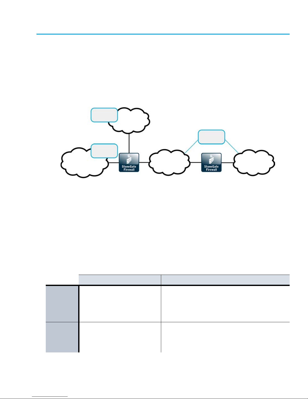
Positioning Firewalls
DMZs
DMZ
Network
Internet
External
Networks
Intranet
Internal
Networks
Restricted
Network
The firewall is a perimeter defense, positioned between networks with different security levels.
Firewalls generally control traffic between:
• External networks (the Internet) and your internal networks.
• External networks (the Internet) and DMZ (demilitarized zone) networks.
• Between internal networks (including DMZs).
Firewalls separate the different networks by enforcing rules that control access from one
network to another.
Illustration 4.1 The Firewall in Different Types of Network Segments
All organizations do not necessarily have all types of networks that are shown here. One firewall
can cover all enforcement points simultaneously if the physical setup makes it practical and if
permitted by the corporate security policy and practices.
The next few pages of this guide explain in more detail how firewalls meet the particular
requirements of each of the different types of networks (external, internal, and DMZ networks).
External to Internal Network Boundary
The most common and most important use for a firewall is to separate internal networks from
the public Internet.
Table 4.2 External Network Considerations for Firewalls
Description Implications on Firewalls
The firewall selects which traffic is permitted into and
Main
purpose
Hosts
Connectivity between the
protected and public networks.
Only equipment that needs to be
directly connected to the public
network, such as routers and
the firewall.
out of the internal networks and translates
addresses between internal IP addresses and public
IP addresses. The firewall is typically also a VPN endpoint.
The communicating hosts in external networks are
unknown in many cases. IP address spoofing is a
possibility. External hosts can be trusted if they are
identified using VPN authentication mechanisms.
Positioning Firewalls
35
Page 36

Table 4.2 External Network Considerations for Firewalls (Continued)
Description Implications on Firewalls
Users
Traffic
volume
Traffic
type
Network
security
Access to this network is open,
but local access to the hosts is
usually restricted to the
administrative staff only.
Varies from low to high, generally
the full bandwidth of all Internet
links combined.
Any type of traffic may be
encountered, especially in
incoming traffic, although some
filtering may be done by the
Internet service provider.
Little or no access controls to
pre-filter traffic arriving from the
Internet. The hosts in this
network should all be securityhardened and actively patched
against known vulnerabilities.
Internal users are known and trusted. Users in public
networks are unknown and untrusted. VPN
authentication and encryption can be used to allow
specific users access from external networks to
internal resources.
Hardware requirements vary depending on the
environment. Clustering allows flexible firewall
throughput adjustments. Multi-Link allows high
availability and load-balancing for outbound
connections. QoS Policies can control the bandwidth
use.
The firewall controls which traffic is allowed access
into your networks, but it is beyond the firewall’s
control what and how much traffic it receives from
the public networks. Advanced inspection checks can
be activated on the firewall and/or on an external
content inspection server depending on the protocol.
The firewall’s policy should be as restrictive as
possible. Generally, new connections are not allowed
from the external to the internal networks (servers
for external services are placed in DMZs). SSH
access to the firewall’s command line from external
networks should be disabled after use.
Internal Network Boundaries
Internal networks are mixed environments with servers and end-user computers. Firewalls
restrict traffic between the different internal networks, but traffic within each network is often
not secured in any significant way.
Table 4.3 Internal Network Considerations for Firewalls
Description Implications on Firewalls
Main
purpose
Hosts
Network services and
connectivity for authorized endusers. Back-end servers that
serve other networks and user
groups.
Mixed environment consisting of
servers, laptops, desktops,
network printers, copiers, etc.
Internal networks transfer confidential data but can
be very permissive for the traffic within the network.
Firewalls can control access between different
internal networks to enforce different security levels
and prevent some types of network threats.
Network communications of the servers and the end
user computers differ in characteristics. Hosts can be
actively maintained and patched to reduce some
types of risks. Access between networks can be
restricted based on the type of host. Firewall logs
provide a record of network use and alerts can be
configured for unusual connection attempts.
36
Chapter 4 StoneGate Firewall/VPN Deployment
Page 37

Table 4.3 Internal Network Considerations for Firewalls (Continued)
Description Implications on Firewalls
Users can be considered trusted, but on various
Users
Authorized personnel.
levels. The firewall authenticates users for access
between internal networks that have different security
levels.
Installation at network choke-points often requires
high-performance hardware. Clustering can provide
load-balancing and high availability in critical
locations.
The firewall policy must balance users’ demands for a
wide range of different services with the need to keep
the internal networks safe. Advanced inspection
features further sanitize permitted communications.
The firewall establishes boundaries between
networks to protect sensitive data and essential
services. Availability of network services sometimes
overrides security.
Traffic
volume
Traffic
type
Network
security
Varies from low to high. Grows
highest at network choke-points
in large environments.
Diverse, with a large number of
different applications
communicating within and in/
out of the network.
A “trusted network” where the
users and the traffic are
considered to be authorized.
DMZ Network Boundaries
DMZ networks (demilitarized zone networks, also known as perimeter networks) are isolated
environments for servers that offer services for mainly external access.
Table 4.4 DMZ Considerations for Firewalls
Description Implications on Firewalls
Main
purpose
Hosts
Users
DMZs provide a limited number
of services, mostly for external
users. The services are often
business-critical and open for
completely public access.
A uniform environment consisting
mainly of servers that often
provide public or semi-public
services.
Mostly unknown, but some
services may be for specific
users. Administrators have wider
privileges.
The firewall selects which traffic is permitted into
and out of the DMZs. The firewall typically also
translates IP addresses from public IP addresses
that are routable in the external networks to private
addresses used in internal networks. VPNs may be
used to provide services for partner-type users.
A limited number of services are provided to an
often large number of hosts. Some types of
administrative access is allowed to a few specific
trusted hosts.
Users are often unknown or authenticated by the
target servers themselves. Firewall authentication
may be useful for restricting administrator access
from internal networks.
Positioning Firewalls
37
Page 38

Table 4.4 DMZ Considerations for Firewalls (Continued)
Description Implications on Firewalls
Traffic
volume
Traffic
type
Network
security
Low to medium, generally the full
bandwidth of all Internet links
combined (shared with other
local networks). Traffic to other
local networks may be high in
volume.
Rather uniform traffic, with only
specific applications and servers
communicating within, into, and
out of the networks.
A network between the trusted
and untrusted security zones
allowing access for authorized
and public use.
Hardware requirements vary depending on the
environment. Clustering allows flexible adjustments
to throughput. The inbound traffic management
features can balance traffic between redundant
servers.
The firewall controls which traffic is allowed access
in and out of each DMZ from external and internal
networks. Usually, only a few specific services have
to be allowed. Advanced inspection checks can be
activated on the firewall and/or on an external
content inspection server depending on protocol.
External access to services makes the servers in a
DMZ a tempting target for attacks. Connections
between the DMZs and to other internal networks
facilitate further attacks, so they must be strictly
controlled.
Positioning Management Center Components
The Firewall/VPN engines have no local interface for day-to-day configuration. A separate
StoneGate Management Center (SMC) is needed to configure and monitor the Firewall/VPN
engines. The SMC consists of the Management Server and the necessary number of Log
Servers and Management Clients. These can be positioned flexibly according to need. Each
Management Server can remotely manage a high number of both StoneGate Firewall and IPS
components. Optionally, you can install one or more Management Servers as backups and one
or more Web Portal Servers for view-only access to the system. Since firewalls are managed
through the Management Server, the Management Clients never connect directly to the firewalls.
The SMC deployment considerations are described in more detail in the StoneGate Management
Center Reference Guide.
38
Chapter 4 StoneGate Firewall/VPN Deployment
Page 39

INTERFACES AND ROUTING
In this section:
Single Firewall Configuration - 41
Firewall Cluster Configuration - 47
Routing and Antispoofing - 59
39
Page 40

40
Page 41

CHAPTER 5
SINGLE FIREWALL CONFIGURATION
A Single Firewall is a firewall that has only one firewall engine (instead of a cluster of two or
more engines).
The following sections are included:
Overview to Single Firewall Configuration (page 42)
Configuration of Single Firewalls (page 42)
Example of a Single Firewall Deployment (page 45)
41
Page 42

Overview to Single Firewall Configuration
A Single Firewall can be deployed at sites where the performance benefits and high availability
provided by a clustered firewall are not essential. High availability of network connections is still
available, since Single Firewalls support Multi-Link. See Outbound Traffic Management
(page 183) and Inbound Traffic Management (page 191) for information on using Multi-Link.
Single Firewalls also support the following features that are unavailable on Firewall Clusters:
• They can have both IPv4 and IPv6 addresses.
• They can have dynamic IPv4 addresses on their interfaces.
• They support wireless links through 3G modems connected to the firewall engine’s USB
ports.
• They support ADSL connections. This feature is only available on specific pre-installed
StoneGate appliances that have an ADSL network interface card.
The Single Firewall engine can be a standard server with an Intel-compatible processor or a
StoneGate appliance. StoneGate UTM adds anti-virus scanning to the standard Firewall/VPN
feature set (see Virus Scanning (page 157)).
This chapter concentrates on network interface configuration, which is the only part of the basic
firewall configuration that has major differences between a Single Firewall and a Firewall Cluster.
Other features, including routing and antispoofing, are explained together for both types of
installations in separate feature-specific chapters.
Configuration of Single Firewalls
StoneGate firewalls are configured and managed centrally through the Management Server. The
Single Firewall element represents the firewall’s configuration on the Management Server. The
main configuration options in the Single Firewall element are the settings related to network
interfaces. This chapter concentrates on those settings.
Dynamic Firewall Interface Addresses
StoneGate Single Firewalls support the use of DHCP and PPPoE to assign dynamic IPv4
addresses on the firewall’s network interfaces. Typically, a dynamic IP address is used in smaller
sites with xDSL connections that have no static IPv4 address available for the firewall. If you use
a 3G modem with the firewall to a provide a wireless link for connections to the Management
Server or to the Internet, the Modem Interface has a dynamic IP address that is assigned
automatically by a PPP daemon.
Instead of an IP address, each dynamic interface is identified in the Management Center by a
DHCP Index, an arbitrary number of your choice that is used to distinguish different dynamic
interfaces from one another.
When a firewall has a fixed IP address, the Management Server can contact the firewall
whenever there is need. When the firewall has a dynamic IP address, the Management Server
does not have a fixed IP address to contact, so the firewall contacts the Management Server
instead. You can also define that a firewall that has a fixed IP address contacts the
Management Server. The frequency of these contacts can be adjusted as necessary. If the
42
Chapter 5 Single Firewall Configuration
Page 43

contact is lost (for example, the Internet connection goes down), the Management Server
queues the commands you have made to the firewall and executes them when contact is reestablished.
Dynamic IP addressing also affects the VPN configuration in much the same way as in
management communications. The Firewall with the dynamic address always has to open the
VPN tunnel. After the VPN tunnel is established, connections can be made in both directions as
usual. VPN client connections can be forwarded through a gateway-to-gateway VPN from some
gateway that has a static IP address (VPN hub configuration).
Internal DHCP Server
Single Firewalls contain an internal DHCP server that can be used to assign IPv4 addresses to
hosts in the protected network. This is meant for branch office type installations where it may be
more practical to assign the IP addresses using the firewall rather than relay the DHCP requests
from a separately maintained local DHCP server or from some other site’s DHCP server through
a VPN.
Configuration Workflow
The following sections provide an overview to the configuration tasks. Detailed step-by-step
instructions can be found in the Online Help of the Management Client and the Administrator’s
Guide PDF, in the section called Elements.
Task 1: Create a Single Firewall Element
To introduce a new Single Firewall to the Management Center, you must define a Single Firewall
element that stores the configuration information related to the firewall engine.
Task 2: Define Physical Interfaces
A Physical Interface represent an actual network port on the engine. The number of defined
Physical Interfaces can be lower than the number of network ports on the engine hardware. A
Normal physical interface represents a single network port on the engine. An Aggregated Link
represents two network ports on the engine. An Aggregated Link provides protection against
hardware failure. You can also use an Aggregated Link in load-balancing mode to increase
throughput.
The numbering of the physical interface definitions is independent of the operating system level
numbering of the actual physical network ports on the engine. By default, the Physical Interface
definitions are mapped to the network ports on the engines one to one, but you can change the
mapping freely using command line tools on the engine.
Task 3: Define VLAN Interfaces
A Virtual Local Area Network (VLAN) is a logical grouping of hosts and network devices that
allows creating several separated networks on a single physical link. To allow this separation,
StoneGate supports VLAN tagging as defined in the IEEE 802.1q standard. One network
interface can support up to 4094 VLANs.
The defined VLAN interfaces are displayed, for example, as “5.202” for network interface 5 with
VLAN 202.
Configuration of Single Firewalls
43
Page 44

Task 4: Define an ADSL Interface
You can optionally configure one ADSL Interface for ADSL connections (ANSI T1.413 i2, G. Lite,
and Annex A are supported). ADSL Interfaces are only available on specific pre-installed
StoneGate appliances that have an ADSL network interface card. Use the number of the ADSL
port on the appliance as the Interface ID of the ADSL Interface.
Task 5: Define IP Addresses
You can define several IPv4 and IPv6 addresses for the same Physical Interface and several
IPv4 addresses for the optional ADSL Interface. IPv6 addresses are not supported on the ADSL
Interface.
If you want to configure multicast routing by using the firewall as an IGMP proxy, the IP
addresses that you define for the downstream interfaces must be the lowest IP addresses
among all the IGMP queriers in the local networks. For more information on IGMP-based
multicast forwarding, see Multicast Routing (page 63).
Task 6: Define Modem Interfaces
You can optionally define one or more Modem Interfaces on the firewall. A Modem Interface
represents the settings of a 3G modem that provides a wireless link to the Internet or to the
Management Server. The 3G modem is connected to a USB port on the firewall engine. Each
Modem Interface is identified with a Modem Number in the Management Client. The Modem
Number is mapped to the modem’s IMEI (international mobile equipment identity) number, and
each modem is assigned a unique ID when you connect the modem to the firewall engine. You
can change the mapping between the modem’s IMEI number and the modem ID through the
engine command line, if necessary.
Task 7: Install the Firewall Engine
During the engine installation, you map the physical network interfaces on the engine and the
modem(s) connected to the USB port(s) on the engine to the Physical Interfaces, the ADSL
Interface, and the Modem Interfaces that you defined in the Management Client.
You can configure the engine automatically using a configuration saved on a USB memory stick.
If you use the automatic engine configuration, the Physical Interface, ADSL Interface, and
Modem Interface definitions in the Management Client are automatically mapped to the physical
network interfaces on the engine and to the modem(s) connected to the engine’s USB port(s). If
you configure the engine automatically through a Modem Interface, you must define Modem
Interface O as the Management interface. You can freely change the Interface ID mapping of the
Physical Interfaces and the Modem number mapping of the Modem interfaces after the initial
configuration using command line tools on the engine. See the Appliance Installation Guide
delivered with the appliance for more information. The Interface ID of the ADSL interface in the
Management Client must be the same as the ADSL port number on the engine. Do not change
the Interface ID mapping of the ADSL Interface through the command line tools on the engine.
During the installation, a basic initial configuration is activated and an initial contact between
the Management Server and the engine is initiated. During the initial contact, the engine
authenticates itself to the Management Server with a one-time password. When this initial
contact succeeds, the engine receives a certificate from the Management Center for
44
Chapter 5 Single Firewall Configuration
Page 45
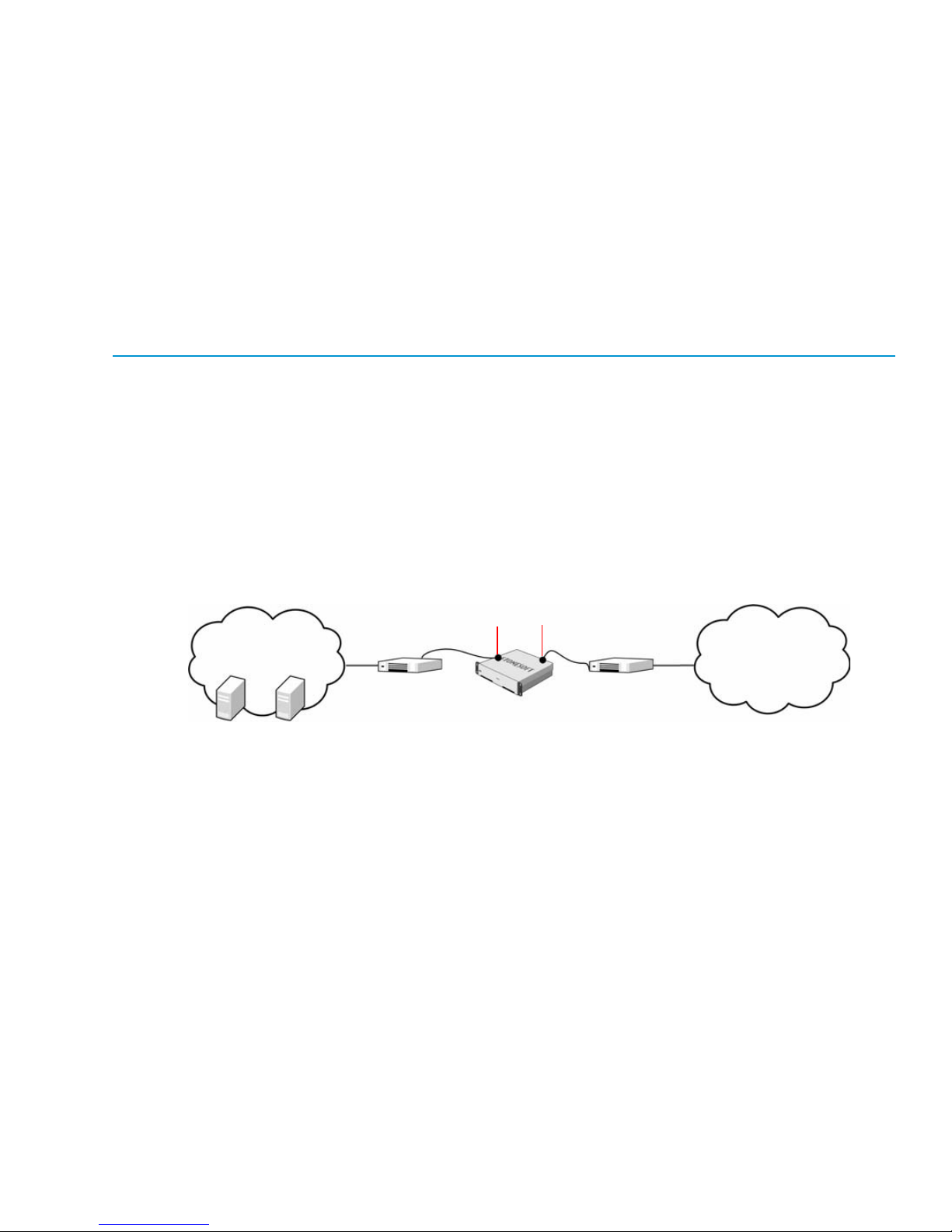
authenticating all subsequent communications—a trust relationship between the engine and
Internet
Intranet
172.16.2.0/24
Branch
Office
Firewall
External Router
212.20.2.1
Internal Router
172.16.2.10
Log Server and
Management Server
at Remote Site
Interface 0
172.16.2.1
Interface 1
212.20.2.254
the Management Server is established. The one-time password expires at that time, since it is
unnecessary from that point onwards.
Task 8: Install a Firewall Policy
After the firewall engine establishes contact with the Management Server, only the primary
control interface with the Management Server is configured. You must install a Firewall Policy
using the Management Client to transfer the complete configuration to the firewall with
information on all interfaces, routing, policies, and other settings. After this is done, the firewall
is ready to start processing traffic.
Example of a Single Firewall Deployment
The examples in this section illustrate common deployment scenarios for a Single Firewall and
general overviews to the steps on how each scenario is configured.
Setting up a Single Firewall
Company A has just opened a new branch office. The administrator at the branch office is
setting up a Single Firewall in the branch office network.
Illustration 5.1 shows the network at the branch office.
Illustration 5.1 Branch Office Network
The Branch Office Firewall has two interfaces with internal and external routers:
• The internal router is connected to Interface ID 0.
• The external router is connected to Interface ID 1.
Example of a Single Firewall Deployment
45
Page 46

StoneGate Management Center has already been installed at the remote site, and the branch
office administrator is now ready to install and configure the Single Firewall. The administrator:
1. Creates a Single Firewall element (Branch Office Firewall) and defines the Log Server at
the remote site as its Log Server.
2. Creates an interface for connecting to the internal router and gives it the following
properties:
•Interface ID: 0.
•IP Address: 172.16.2.1.
3. Creates an interface for connecting to the external router and gives it the following
properties:
•Interface ID: 1.
•IP Address: 212.20.2.254.
4. Saves the initial configuration of the Branch Office Firewall on a USB stick.
5. Installs the firewall engine in the server room.
6. Inserts the USB stick in the firewall, turns it on, and waits until the Management Client
shows that contact is established between the engine and the Management Server.
7. Checks the routing configuration and adds the first few rules for allowing traffic through
the firewall.
8. Installs a Firewall Policy using the Management Client to transfer the first working
configuration to the firewall.
Adding a New Interface to an Existing Configuration
In the previous example, the administrator initially configured the firewall at the company’s new
branch office with just two interfaces. Now the administrator decides to add a physically
separated DMZ network for access to/from that office’s mail server to properly control both
internal and external traffic with this publicly exposed server. The administrator:
1. Creates an interface for the DMZ and gives it the following properties:
•Interface ID: 2.
•IP Address: 192.168.2.1.
2. Creates new rules in the firewall’s policy to allow traffic to/from the DMZ and NAT rules to
translate between the private and public IP address of the mail server.
3. Connects the new DMZ router to the firewall.
4. Installs a Firewall Policy using the Management Client to transfer the new working
configuration to the Firewall.
46
Chapter 5 Single Firewall Configuration
Page 47

CHAPTER 6
FIREWALL CLUSTER CONFIGURATION
A Firewall Cluster is a group of firewall nodes that work as a single logical entity to share the
load of traffic processing and provide redundancy, ensuring the availability of network services
to the users.
The following sections are included:
Overview to Firewall Cluster Configuration (page 48)
Configuration of Firewall Clusters (page 49)
Using a Firewall Cluster (page 55)
Examples of Firewall Cluster Deployment (page 57)
47
Page 48

Overview to Firewall Cluster Configuration
A StoneGate Firewall Cluster consists of 2 to 16 nodes that function as a single entity.
Clustering is a standard feature that you can activate on any StoneGate Firewall/VPN
installation if you have two or more licensed engines.
You can also configure Multi-Link on the Firewall Cluster to provide high-availability for inbound
and outbound connections. See Outbound Traffic Management (page 183) and Inbound Traffic
Management (page 191) for more information. StoneGate UTM adds anti-virus scanning to the
standard Firewall/VPN cluster feature set (see Virus Scanning (page 157)).
This chapter concentrates on the configuration of network interfaces, IP addresses, and
clustering, which are the only parts of the basic configuration where there are major differences
between a Single Firewall and a Firewall Cluster. The section Using a Firewall Cluster (page 55)
describes other configuration tasks that you may do in the Firewall Cluster element properties.
Other features, including routing and antispoofing, are explained together for both types of
installations in separate feature-specific chapters.
Benefits of Clustering
A Single Firewall can be a single point of failure. This can affect the availability of business
critical applications and complicate the maintenance of the firewall equipment. Clustering
firewall nodes can significantly reduce the risk of these problems.
The StoneGate Firewall/VPN solution uses built-in clustering technology. No additional software
or hardware is needed to cluster several nodes. If a node itself or the surrounding network
equipment malfunctions, the other nodes in the cluster take over the traffic processing,
minimizing any disruptions to the traffic flow. Similarly, maintenance is easier with a cluster,
because individual nodes can be taken offline and even exchanged for new hardware without
causing service outages.
Firewall Clusters also balance the load of traffic processing between the firewall nodes. You can
flexibly add nodes to scale up the Firewall Cluster, improving the throughput and performance.
Communication Between the Nodes
The Firewall Cluster nodes exchange information constantly. The state tables that list open
connections (state sync) and the operating state of the other nodes (heartbeat) are exchanged.
This exchange of information ensures that all nodes have the same information about the
connections and that if a firewall node becomes unavailable, the other nodes of the cluster
immediately notice this. The exchange of information between clustered StoneGate nodes is
synchronized through selected interfaces via a heartbeat network using multicast
transmissions. The heartbeat messages are authenticated, and can also be encrypted if
necessary (authentication is enabled by default).
48
Chapter 6 Firewall Cluster Configuration
Page 49

Hardware
The hardware the cluster nodes run on does not need to be identical. Different types of
equipment can be used as long as all nodes have enough network interfaces for your
configuration.
If equipment with different performance characteristics is clustered together, the load-balancing
technology automatically distributes the load so that lower performance nodes handle less
traffic than the higher performance nodes. However, when a node goes offline, the remaining
node(s) must be able to handle all traffic on their own to ensure high availability. For this reason,
it is usually best to cluster nodes with similar performance characteristics.
Configuration of Firewall Clusters
StoneGate firewalls are configured and managed centrally through the Management Server. The
Firewall Cluster element represents the Firewall Cluster’s configuration on the Management
Server. The main configuration options in the Firewall Cluster element include the settings
related to network interfaces and clustering. This chapter concentrates on those settings.
Load Balancing
In a Firewall Cluster configuration, the recommended way to cluster the nodes is load-balanced
clustering, where traffic is balanced between the nodes dynamically. Load-balanced clustering
provides both fault tolerance and performance benefits.
The traffic arriving at the Firewall Cluster is balanced across the nodes according to the settings
of the cluster’s load balancing filter. This filtering process distributes packets between the
firewall nodes and keeps track of packet distribution. The Firewall determines the packet
ownership of the nodes by comparing the incoming packet with node-specific values based on
the packet headers. The load-balancing filter is pre-configured for optimal performance and is
not meant to be adjusted independently by the system administrators.
The Firewall Cluster keeps track of which node is handling each ongoing connection. As a result,
all packets that are part of a given connection can be handled by the same node. Some
protocols use multiple connections, which are sometimes handled by different nodes, but this
does not usually affect the processing of the traffic.
Standby Operation
In standby clustering, only one node at a time processes traffic, and other nodes wait on
standby, ready to take over when the currently active node goes offline. Nodes that should not
take over automatically can be set offline as usual. The drawback with standby mode is that
there is no performance gain in clustering the firewalls.
Configuration of Firewall Clusters
49
Page 50

Network Interfaces and IP Addresses
Node 1
Node 2
Firewall Cluster
Internet
Protected
Network
Interface ID 0
NDI 0
Interface ID 1
CVI 1 and NDI 1
Interface ID 2
CVI 2 and NDI 2
Interface ID 1
CVI 1 and NDI 1
Interface ID 2
CVI 2 and NDI 2
Interface ID 0
NDI 0
To work as replacements for each other, cluster members must have near-identical network
interface configurations. A Physical Interface definition in the Management Client always
represents a network interface definition on each node of the cluster. The table below explains
the two types of IP addresses that you can add to a Physical Interface definition. You can add
several IP addresses of each type to a single Physical Interface. Only IPv4 addresses are
supported on firewall clusters.
Table 6.1 Firewall Cluster IP Address Types
IP Address Type Description
A CVI handles the traffic directed to the Firewall Cluster for
inspection. The CVI is shared by all the nodes in the cluster. It
Cluster Virtual IP Address (CVI)
Node Dedicated IP Address (NDI)
depends on the selected clustering mode how this shared IP
address is used. The CVI gives the cluster a single identity on the
network, reducing the complexity of routing and network design.
An NDI handles all communication for which the end-point is the
node itself, including node-to-node, Management Server to node,
and node-initiated connections. Each node in the cluster has its
own dedicated IP address that is used as the NDI. In most cases,
you must define an NDI for each physical interface. If necessary,
you can define more than one NDIs for the same physical interface.
Illustration 6.1 Cluster Interfaces
Illustration 6.1 shows how CVIs and NDIs are used on a Firewall Cluster. In this example, the
Interface ID 0 on each node has an NDI that is used for heartbeat traffic between the nodes in a
dedicated network. There is no CVI on Interface ID 0, since it handles only node-to-node traffic.
Interface ID 1 has a CVI that is used for Internet traffic (for example, Web browsing), and it also
has an NDI for traffic that the nodes send toward the Internet (for example, automatic tests the
firewall uses to check connectivity). Interface ID 2 has a CVI for protected network traffic and an
NDI for management connections to and from the nodes.
50
Chapter 6 Firewall Cluster Configuration
Page 51

Clustering Modes
There are several modes for how traffic can be directed to the cluster. The modes are explained
in the table below. If necessary, refer to the documentation for the router, hub, or switch you are
using for information on which mode is best in your environment.
Table 6.2 Clustering Modes
Mode Description
This is the recommended clustering mode.One node per physical interface is the
dispatcher that handles the distribution of traffic between the different nodes for all
Packet Dispatch
Unicast MAC
Multicast MAC
CVIs on that physical interface. The assigned node handles the traffic processing.
No additional switch configuration is needed.
This mode can also be used with hubs but it is not the optimal clustering mode with
hubs.
This is the recommended mode when hubs are used. This mode cannot be used
with most switches.
All the nodes in the cluster share the same unicast MAC address for the CVI. All the
nodes in the cluster see all the packets.
The nodes share the same multicast MAC address for the CVI. All the nodes in the
cluster see all the packets.
Do not use this mode instead of the packet dispatch mode except in special cases
(for example, if the nodes have uncertified network interface cards whose MAC
address cannot be changed).
The clustering works otherwise the same as in the Multicast MAC mode except that
Multicast MAC
with IGMP
the engine answers to IGMP membership queries.
This mode allows limiting multicast flooding when the switch does not support static
MAC address forwarding tables.
All CVIs on the same physical interface must use the same mode. It is possible to set different
cluster modes for CVIs that are defined for different physical interfaces.
As Packet Dispatch mode is the recommended clustering mode, this section explains only the
Packet Dispatch mode in more detail. For more information on the other clustering modes, see
Multicasting (page 301).
How Packet Dispatch Works
In Packet Dispatch mode, the node selected as the dispatcher on the physical interface assigns
the packets to one of the nodes (to itself or to some other node). The assigned node then
handles the actual resource-intensive traffic processing. The dispatcher attempts to balance the
nodes’ loads evenly, but assigns all packets that belong to the same connection to the same
node. The node that acts as the packet dispatcher can be (and often is) different for CVIs on
different physical interfaces. Illustration 6.2 shows an example of how packet dispatch handles
a connection.
Configuration of Firewall Clusters
51
Page 52
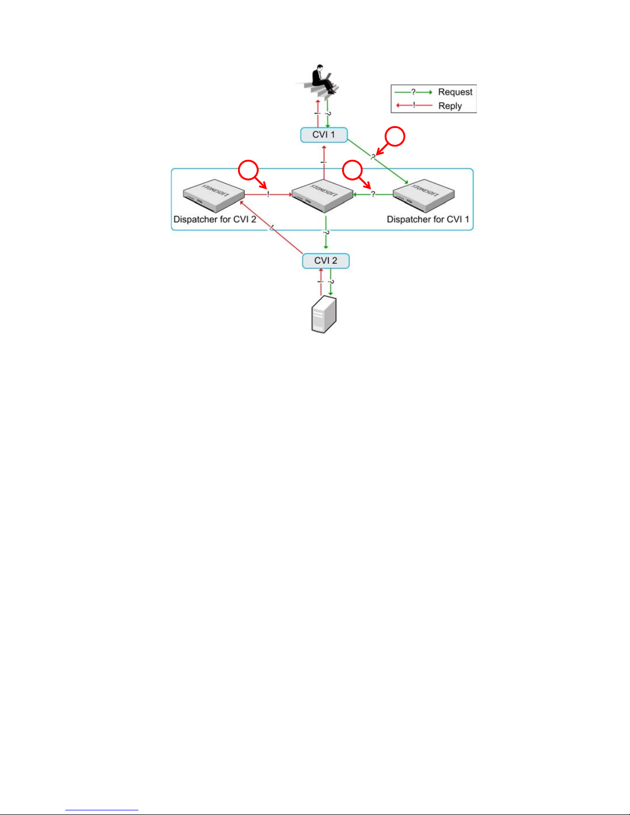
Illustration 6.2 Packet Dispatch CVI Mode
1
23
1. The dispatcher node for CVI 1 receives a new packet.
2. The dispatcher node either handles the packet itself or dispatches the packet to one of
the other firewall nodes for processing according to the load-balancing filter. The packet is
sent to the other node through the interface the packet arrived from.
3. The dispatcher node for CVI 2 forwards the replies within the open connection to the
same node.
One node is responsible for handling each connection. The node responsible for the connection
handles all resource-consuming tasks: it determines if the connection is allowed to continue,
translates addresses as necessary, and logs the connection.
The dispatcher node controls the CVI’s IP address and MAC address. The other nodes use their
own physical interface’s MAC address for the same CVI. When the dispatcher node goes offline,
one of the other nodes becomes the dispatcher node. The new dispatcher node changes its
interface’s MAC address to the address defined for the Packet Dispatch CVI.
The network switch must update its address table without significant delay when the packet
dispatcher MAC address is moved to another firewall node. This is a standard network
addressing operation where the switch learns that the MAC address is located behind a
different switch port. Then, the switch forwards traffic destined to the CVI address to this new
packet dispatcher.
52
Chapter 6 Firewall Cluster Configuration
Page 53

Configuration Workflow
The following sections provide an overview of the configuration tasks. Detailed step-by-step
instructions can be found in the Online Help of the Management Client and the Administrator’s
Guide PDF, in the section called Elements.
Task 1: Create a Firewall Cluster Element
To introduce a new Firewall Cluster to the Management Center, you must define a Firewall
Cluster element that stores the configuration information related to the firewall engines.
Task 2: Create Physical Interfaces
Physical Interfaces represent the network ports on the engines. The number of defined Physical
Interfaces can be lower than the number of network ports on the hardware. In a firewall cluster,
a Normal Interface definition represents a single network port on all the nodes of the cluster. An
Aggregated Link represents two network ports on one node that function as a single logical
interface.
The numbering of the Physical Interface definitions is independent of the operating system level
numbering of the actual physical network interfaces on the engine. By default, the Physical
Interface definitions are mapped to the actual network interfaces on the engines one to one, but
you can change the mapping freely using command line tools on the engine. This mapping can
be done differently from node to node as long as you take care that the interface that
represents the same network interface on each node is correctly cabled to the same network.
Task 3: Define VLAN Interfaces
A Virtual Local Area Network (VLAN) is a logical grouping of hosts and network devices that
allows creating several separated networks on a single physical link. To allow this separation,
StoneGate supports VLAN tagging as defined in the IEEE 802.1q standard. One network
interface can support up to 4094 VLANs.
VLANs can also make it easier to deploy geographically distributed Firewall Clusters (for
example, a cluster whose nodes are located in different buildings), as fewer physical interfaces
and less cabling is needed.
When you create a VLAN interface, the CVI mode and MAC address are defined commonly for all
virtual interfaces configured for the same Physical interface definition. The defined VLAN
interfaces are displayed, for example, as “5.202” for network interface 5 with VLAN 202.
Configuration of Firewall Clusters
53
Page 54

Task 4: Configure Physical or VLAN Interfaces
There are two types of IP addresses that you can define on Physical Interfaces: Cluster Virtual IP
Addresses (CVIs) and Node Dedicated IP Addresses (NDIs). You can define as many CVIs and
NDIs per Physical Interface as you need. The two different IP address types are required due to
the special requirements of clustering.
• A CVI is used for traffic directed to the Firewall Cluster for inspection. Each CVI is shared
shared by all the nodes in the cluster. The CVI allows the surrounding network to see the
cluster as a single entity.
• An NDI handles all traffic for which the end-point of the communication is a node itself. Each
node in the cluster has a dedicated IP address. The NDI that you define for each node allows
the communications to reach a particular node.
If the Physical Interface is an Aggregated Link, both the interfaces that belong to the Aggregated
Link share the same IP address definitions.
Each CVI inherits the MAC address defined for the Physical Interface. The MAC/IP address pair
remains the same all the time as only the location of the MAC address changes to the current
dispatcher node (packet dispatch). This makes the external network equipment forward traffic to
the correct node for dispatching. The CVIs on different Physical Interfaces cannot have duplicate
MAC addresses.
The NDIs are used for node-to-node communications, for traffic between each individual node
and the Management Server and Log Server, as well as communications with external
components (such as authentication servers, or hosts that are probed in network connectivity
tests). When you define NDIs, you must define both node-specific properties (such as the
node’s IP address) and properties that are shared by all the nodes in the cluster. All nodes must
have the same netmask value for their NDI.
To ensure correct operation in all cases, we recommend you define an NDI for all nodes on each
Physical Interface. If there is a shortage of IP addresses, it is possible to leave some Physical
Interface without an NDI. If a Physical Interface does not have an NDI IP address for a node, the
node uses an IP address from one of the other NDIs (the default IP address for outgoing traffic)
when initiating communications through that interface. Gratuitous ARP requests used for
updating the MAC address/IP address relationship in the Packet Dispatch mode may be
affected by this configuration. The ‘borrowed’ IP address can be used without issues with
routers that strictly follow the ARP standard as long as the IP address used is valid from the
routing point of view. However, some routers may not reply to the firewall’s gratuitous ARP
requests in this case, and static ARP entries may be required in the firewall’s configuration to
allow communications.
If you want to configure multicast routing by using the firewall as an IGMP proxy, the IP
addresses that you define for the downstream interfaces must be the lowest IP addresses
among all the IGMP queriers in the local networks. For more information on IGMP-based
multicast forwarding, see Multicast Routing (page 63).
54
Chapter 6 Firewall Cluster Configuration
Page 55

Task 5: Install the Firewall Engines
During the engine installation, you map the network interfaces on the engine to the Physical
Interface definitions created in the Management Client. See the Appliance Installation Guide
delivered with the appliance for more information.
During the installation, a basic initial configuration is activated and an initial contact between
the Management Server and each engine is initiated. During the initial contact, each engine
authenticates itself to the Management Server with its own single-use password. When this
initial contact succeeds, the engine receives a certificate from the Management Center for
authenticating all subsequent communications - a trust relationship between that engine and
the Management Server is established.
Task 6: Install a Firewall Policy
The engines do not receive any clustering settings until the first time you install a policy on them
and the working configuration is received from the Management Server. After the firewall
engines have made initial contact with the Management Server, only the primary control
interface with the Management Server is configured. You must install a Firewall Policy using the
Management Client to transfer the complete interface configuration to the firewall.
Using a Firewall Cluster
The main points of Firewall Cluster configuration are explained in the preceding sections of this
chapter. This section illustrates some additional concepts for working with Firewall Clusters:
• Internal DHCP Server (page 55)
• Node State Synchronization (page 56)
• Security Level for State Synchronization (page 56)
• Manual Load Balancing (page 56)
Caution – Do not modify the firewall’s Advanced Settings without due consideration. An
invalid configuration of the parameters may lead to system instability or malfunction.
Internal DHCP Server
Firewall clusters contain an internal DHCP server that can be used to assign IPv4 addresses to
hosts in the protected network. This is meant for small installations where it may be more
practical to assign the IP addresses using the firewall rather than relay the DHCP requests from
a separately maintained local DHCP server or from some other site’s DHCP server through a
VPN.
Using a Firewall Cluster
55
Page 56
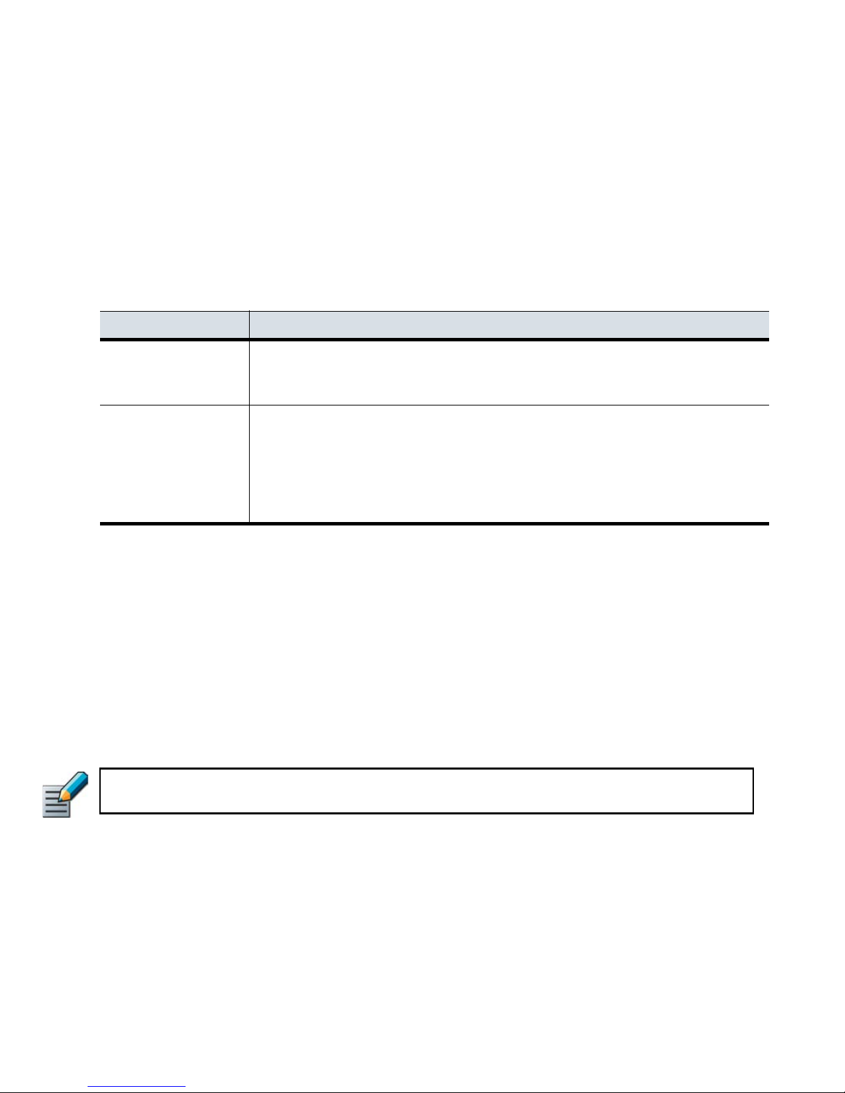
Node State Synchronization
State synchronization is essential for the following features:
• Dynamic load balancing.
• Transparent switchover of nodes in case of failure or maintenance.
• Handling of related connections when a service (for example, FTP) opens multiple
connections.
Regular, timer-launched synchronization events are needed to synchronize state data and to
avoid cutting connections in case of node failure. Timed synchronization events are divided into
full and incremental sync messages (see Table 6.3 for details).
Table 6.3 Sync Messages
Type Explanation
Contain all connection data about the traffic handled by a node at the time when
Full Sync Messages
Incremental Sync
Messages
the message was sent. When new data is received, it replaces the existing
data. Full sync requires more bandwidth and processing time.
Contain only data on connections that were created or changed since the last
full or incremental sync message. Incremental sync needs less bandwidth and
processing time. Since the incremental changes are sent only once, the system
may lose connections if the data is lost. While able to produce accurate data
with frequent updates, incremental sync requires full sync to provide reliable
synchronization data.
By default, a combination of full and incremental sync messages is exchanged between nodes.
This way, frequent updates on incremental changes and recurrent reports on existing
connections are combined.
Security Level for State Synchronization
Because synchronization controls the inter-node traffic within a heartbeat network, you must
ensure the security of the heartbeat and synchronization data. The inter-node traffic can be
authenticated, or both authenticated and encrypted. Inter-node traffic can also optionally be
sent without authentication or encryption. However, this makes it possible to both sniff
synchronization data and send fraudulent messages to open connections.
Note – Independent of the security level, all critical information such as passwords and
encryption keys are protected. They are never sent in plaintext.
Manual Load Balancing
The Firewall Cluster’s load balancing filter can be manually modified if there is a specific need
for modifications. Any modified load balancing parameters are combined with the automatically
created filtering entries. However, modifying the load balancing parameters of the Firewall
Cluster without careful consideration can cause conflicts in filtering decisions.
56
Chapter 6 Firewall Cluster Configuration
Page 57

Examples of Firewall Cluster Deployment
Headquarters
Intranet
Management
Network
HQ Cluster
Heartbeat
Internet
ID O
ID O
ID 1ID 2
ID 4 ID 3
ID 1
ID 3ID 4
ID 2
Internal Switch Internal Switch
ISP A Switch
ISP B Switch
Node 2Node 1
HQ Log
Server and
Management
Server
ISP BISP A
The examples in this section illustrate the configuration of a Firewall Cluster with general steps
on how each scenario is configured.
Setting up a Firewall Cluster
The administrators at the headquarters of Company A want to set up a Firewall Cluster. The
cluster consists of two cluster nodes: Node 1 and Node 2. The HQ Cluster Firewall has a
dedicated heartbeat network (10.42.1.0/24), and it is connected to two internal networks:
Headquarters Intranet (172.16.1.0/24) and Management Network (192.168.10.0/24). It uses
Multi-Link to ISP A and ISP B for its connection to the Internet.
Illustration 6.3 Headquarters Network
The administrators:
1. Create a Firewall Cluster element (HQ Cluster) and define HQ Log as its Log Server.
2. Define the physical interfaces 0-4.
3. Define the CVIs and NDIs for the physical interfaces. Except for the IP addresses, the
node-specific properties for Node 1 and Node 2 are the same. See Table 6.4.
Examples of Firewall Cluster Deployment
57
Page 58

Table 6.4 Cluster Interfaces
Interface ID Type IP Address Comment
0 NDI for Node1 10.42.1.1 Heartbeat
0 NDI for Node2 10.42.1.2 Heartbeat
1 CVI 129.40.1.254 ISP B
1 NDI for Node1 129.40.1.21 ISP B
1 NDI for Node2 129.40.1.22 ISP B
2 CVI 212.20.1.254 ISP A
2 NDI for Node1 212.20.1.21 ISP A
2 NDI for Node2 212.20.1.22 ISP A
3 CVI 192.168.10.1 Management Network
3 NDI for Node1 192.168.10.21 Management Network
3 NDI for Node2 192.168.10.22 Management Network
4 CVI 172.16.1.1 Headquarters Intranet
4 NDI for Node1 172.16.1.21 Headquarters Intranet
4 NDI for Node2 172.16.1.22 Headquarters Intranet
4. Save the initial configuration of the engines in the Management Client.
5. Map the interface identifiers in the configuration to the physical interfaces on each
engine’s command line and establish contact between each engine and the Management
Server.
6. Install a Firewall Policy on the Firewall Cluster in the Management Client to transfer the
working configuration to the firewall engines. The nodes exchange authentication
information and begin to work as a cluster.
Adding a Node to a Firewall Cluster
Company A’s Firewall currently consists of two nodes. However, the load on the Firewall is
exceptionally high, so the administrator has decided to add another node to ensure continuity of
network services even when one of the nodes is offline. The administrator does the following:
1. Adds a third node in the Firewall Cluster element’s properties.
2. Defines the node-specific IP addresses for the NDI interfaces of the new node.
•The cluster-level interface configuration does not need adjustments, since it is shared by
all nodes.
3. Installs the new engine and performs the initial configuration.
4. Refreshes the security policy of the Firewall Cluster.
58
Chapter 6 Firewall Cluster Configuration
Page 59

CHAPTER 7
ROUTING AND ANTISPOOFING
Routing is the process of defining through which network interface StoneGate forwards traffic
from a source address to a destination address. Antispoofing is the process of defining which
addresses are considered valid source addresses for the network(s) connected to each
interface.
The following sections are included:
Overview to Routing and Antispoofing (page 60)
Configuration of Routing and Antispoofing (page 60)
Using Routing and Antispoofing (page 63)
Examples of Routing (page 64)
59
Page 60

Overview to Routing and Antispoofing
In addition to examining packets, a firewall has to determine how to route packets. For the most
part, StoneGate automates the routing and antispoofing configuration. Much of the
configuration is generated automatically based on the IP addresses of the network interfaces.
Configuration of Routing and Antispoofing
The routing and antispoofing information is displayed and configured graphically in interfacebased trees in the Routing view and Antispoofing view. The routing information is stored on the
Management Server. The information is transferred to the firewalls when the firewall policies are
installed or refreshed.
In addition to the routing information that is automatically generated based on the interface
definitions, you must manually add any networks that are not directly connected to the firewall
to the routing tree. Similarly, you must also add a default route for packets whose destination IP
address is not included anywhere else in the routing tree.
IP address spoofing is an attack where the source IP address in a packet is modified to gain
unauthorized access or to cause a denial-of-service (DoS). Such attacks can be prevented with
antispoofing rules. The antispoofing configuration is generated automatically based on the
routing tree. Antispoofing is always enforced on all interfaces. You can change the antispoofing
configuration, but in most environments, there is no need to do so.
Reading the Routing and Antispoofing Trees
The Routing view automatically displays the interfaces and a Network element for each network
that is directly connected to the firewall. The Network is created based on the IP address(es)
that you define for each interface. Interfaces that belong to an aggregated link always share the
same routing information. Only the first interface that belongs to the aggregated link is
displayed in the Routing and Antispoofing views.
When the firewall reads routing definitions, it selects the most specific route and antispoofing
definition it finds for each packet. The firewall first checks if there is a route defined for the
specific destination IP address of the packet (a Host element), then checks routes to the
defined networks (a Network element), and finally uses the default route (the Any Network
element) if none of the other routes match the packet’s destination address. If there are
overlapping definitions, the more specific one is considered first.
Example Interface 1 has a Host element for 192.168.0.202 and Interface 2 has a Network element for
192.168.0.0/24, a packet to 192.168.0.202 is routed through Interface 1, and the Interface
2 definition is not considered for those packets at all.
60
Chapter 7 Routing and Antispoofing
Page 61
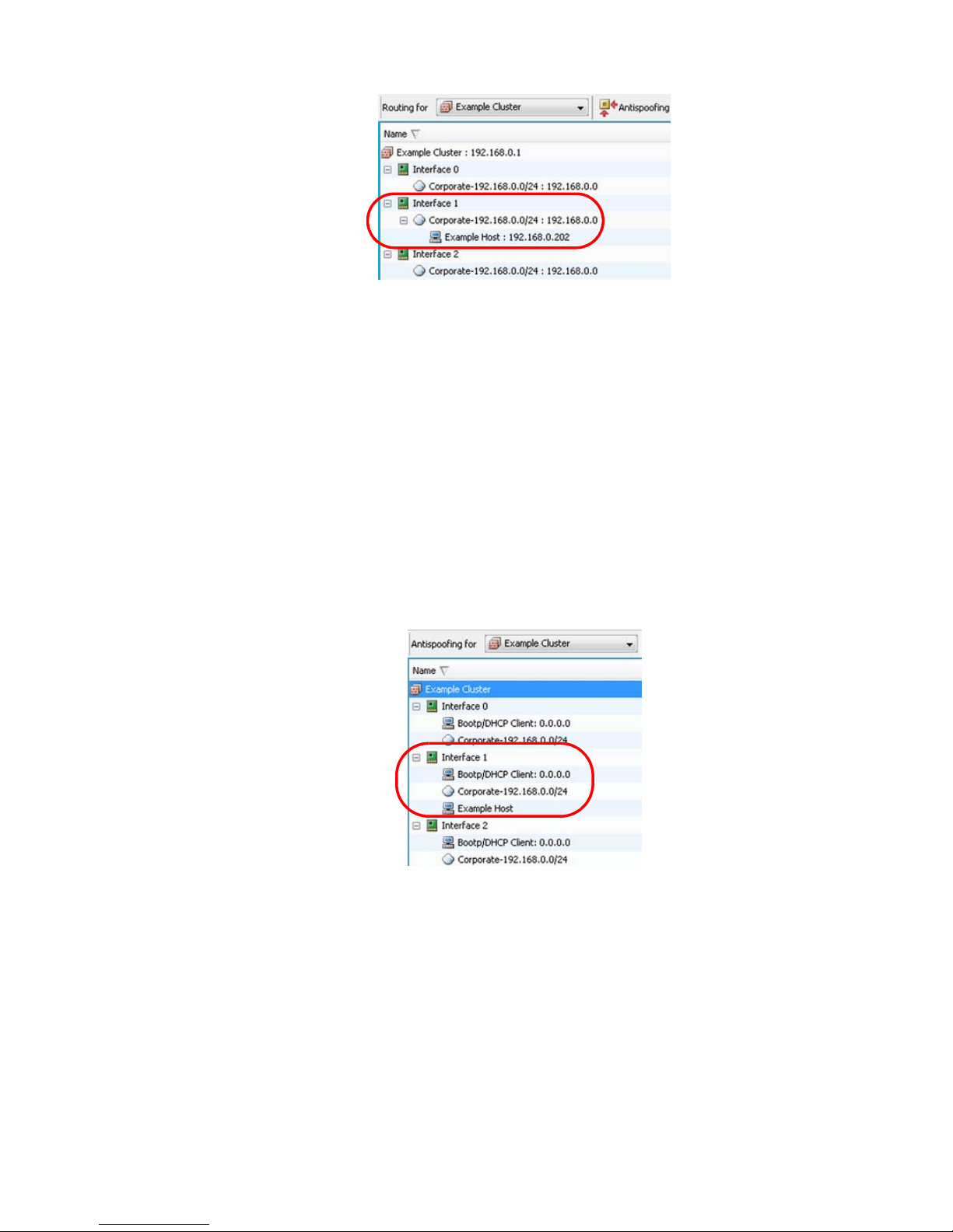
Illustration 7.1 Example: The More Specific Destination is Considered First in Routing
Interface 1 is always used for a destination of 192.168.0.202 because it has a Host element
with the most specific address under it.
The Antispoofing view defines the source addresses of traffic that are considered valid (not
spoofed) for each interface of a Single Firewall and Firewall Cluster element. If an interface
receives a packet with a source address that is not a valid address for the network(s) connected
to that interface, the packet is discarded. This is the case, for example, when an external
interface receives a packet with an internal source. The firewall selects the most specific
antispoofing definition it finds for each packet.
Example In the Antispoofing tree automatically generated based on the routing example above,
antispoofing discards any traffic with the address 192.168.0.202 if it originates from
Interface 2, because it has the less specific definition for that address (the Network
192.168.0.0/24).
Illustration 7.2 Only The Most Specific Destination is Considered Valid in Antispoofing
Packets from Example Host (192.168.0.202) are only considered valid if they originate from
Interface 1, because it has the most specific route to the host’s address.
Example To allow the traffic to originate from both interfaces, you would also have to add the Host
element for 192.168.0.202 under Interface 2, so that the definitions are equally specific
(both interfaces contain the Host element) and therefore both definitions are valid at the
same time.
Configuration of Routing and Antispoofing
61
Page 62

Illustration 7.3 Both Interfaces are Considered Valid
Both Interface 1 and Interface 2 are considered valid routes to Example Host (192.168.0.202)
because the Host element is included under both interfaces.
Multi-Link Routing for Single and Clustered Firewalls
Multi-Link uses multiple network links (NetLinks) to balance the load of outbound traffic and
ensure high availability of Internet connectivity. With each new outbound connection, the system
selects the fastest route for the connection from the available NetLinks. See Outbound Traffic
Management (page 183) for more information on Multi-Link for outbound connections.
Illustration 7.4 NetLinks in Routing View
In Illustration 7.4, a Multi-Link configuration is used to define a default route to the Internet (to
“Any network”) through the ISP A and ISP B NetLinks.
Default Elements
Networks that correspond to the IP addresses of each interface are automatically added to the
routing and antispoofing configurations of Firewall elements.
The system includes a default network element called Any network, which is needed to define
the default route. The system also includes a Host element for Bootp/DHCP clients in the
Antispoofing view for Firewall elements.
62
Chapter 7 Routing and Antispoofing
Page 63

Configuration Workflow
The following sections provide an overview of the configuration tasks. Detailed step-by-step
instructions can be found in the Online Help of the Management Client and the Administrator’s
Guide PDF, in the section called Routing.
Task 1: Add Router or NetLink
A Router or a NetLink element represents a next-hop gateway that forwards packets to
network(s) that are not directly connected to the Firewall element(s).
Task 2: Add Network(s)
A Network element represents the IP addresses of a network or a subnetwork to which the
Router or the NetLink forwards the traffic.
Task 3: Refresh Firewall Policy
Changes to the routing or antispoofing configuration are only transferred to the firewall engine
when you refresh the firewall policy.
Using Routing and Antispoofing
In addition to simple routing or Multi-Link routing, you can use policy routing and IP multicast
routing with Single Firewall and Firewall Cluster elements.
Policy Routing
With policy routing you can route traffic through a selected gateway. These policy routing entries
override other routing configuration defined in the Routing view.
A policy routing entry includes a source IP address, a destination IP address, netmasks or
prefixes for the source and destination addresses, and the IP address of the selected gateway.
Both IPv4 and IPv6 addresses are supported in policy routing on single firewalls.
Antispoofing configuration may need to be changed accordingly when using manual policy
routing entries.
Multicast Routing
IP multicasting is the transmission of an IP datagram to all hosts in a multicast host group,
which is identified by a single destination IP address. See Multicasting (page 301) for more
information. You can configure static multicast and IGMP-based multicast forwarding of IPv4
traffic.
Static multicast does not rely on IGMP (Internet Group Management Protocol) messaging.
Because of the static nature of the configuration, static multicast is suitable for enduring
configurations, such as mutually agreed multicast traffic between organizations.
In IGMP-based multicast forwarding (IGMP proxying), the firewall maintains a list of subscriptions
to the multicast host group and forwards multicast traffic to the subscribed hosts. The firewall
periodically queries the downstream networks for hosts that want to join the multicast host
group. The firewall also processes unsolicited IGMP join/leave requests received from
Using Routing and Antispoofing
63
Page 64

downstream networks. As multicast traffic is only sent to the currently subscribed hosts, IGMPbased multicast forwarding can save bandwidth and provide faster service. IGMP-based
multicast forwarding is only supported in tree topology networks. See RFC 4605 for more
information.
If you use Multi-Link together with IGMP-based multicast forwarding, make sure that you do not
create routing loops. If you add a NetLink to a firewall’s upstream interface, do not add a
NetLink to any of the firewall’s downstream interfaces.
Modifying Antispoofing
In rare cases you may need to modify the default antispoofing definitions to make exceptions to
the antispoofing rules (for example, if you have defined policy routing manually). You can also
disable antispoofing for an interface, if necessary.
Examples of Routing
The examples in this section illustrate some common uses of routing for Single Firewall and
Firewall Cluster elements in StoneGate and general steps on how each scenario is configured.
Routing Traffic with Two Interfaces
Company A needs to route traffic to the Internet as well as to the internal Network B, which is
not directly connected to the company’s Branch Office Firewall. The company’s administrators
decide to create a separate route to the internal Network B and a default route for traffic to the
Internet. The administrators:
1. Open the Routing view for the Branch Office Firewall.
2. Add a Router and Network B under Interface 0.
3. Add a Router and the default element “Any network” under Interface 1.
4. Refresh the firewall policy on the Branch Office Firewall.
Routing Internet Traffic with Multi-Link
Company B wants to ensure high availability of Internet connections through the company’s
firewall. The company’s administrators decide to use Multi-Link routing with two NetLinks to
balance Internet connections. They:
1. Create two NetLinks.
2. Combine the NetLinks into an Outbound Multi-Link element to balance the connections.
3. Add one of the NetLinks under Interface 1 and the other NetLink under Interface 2 in the
Routing view.
4. Add the default route “Any network” under the NetLinks.
5. Add a NAT rule to the firewall policy to balance the connections between the NetLinks.
6. Refresh the firewall policy.
64
Chapter 7 Routing and Antispoofing
Page 65

Routing Traffic to Networks That Use Same Address Space
Firewall
Cluster
Host 2
10.0.0.102
Host 1
10.0.0.101
Router A
Router B
Network A
192.168.1.0/24
Network B
192.168.1.0/24
Company C’s network is connected to two partners: Network A and Network B. The Network A
and the Network B partners use the same address space in their internal networks.
Illustration 7.5 Policy Routing in Company C
There are two hosts in Company C’s network. Host 1 works only with the Network A partner and
Host 2 only with the Network B partner. The administrators at Company C decide to use policy
routing to route the traffic between Company C’s network and the two partner sites. The
administrators:
1. Create policy routing entries for Host 1 and Host 2 on the Firewall HQ Cluster as shown in
Illustration 7.6.
Illustration 7.6 Policy Routing Entries for Host 1 and Host 2
2. Modify the antispoofing rules so that they take into account the routing defined with the
policy routing entries.
3. Refresh the firewall policy on the Firewall HQ Cluster.
Examples of Routing
65
Page 66

66
Chapter 7 Routing and Antispoofing
Page 67

ACCESS CONTROL
OLICIES
P
In this section:
Firewall Policies - 69
Access Rules - 83
Inspection Rules - 99
Network Address Translation (NAT) Rules - 109
Protocol Agents - 123
User Authentication - 133
HTTPS Inspection - 147
Web Filtering - 153
Virus Scanning - 157
External Content Inspection - 161
Situations - 169
Blacklisting - 175
67
Page 68

68
Page 69

CHAPTER 8
FIREWALL POLICIES
Policy elements are containers for the lists of rules that determine how the firewall examines
traffic. The policy elements include Firewall Template Policies, Firewall Policies, and Firewall
Sub-Policies.
The following sections are included:
Overview to Firewall Policies (page 70)
Configuration of Policy Elements (page 72)
Using Policy Elements and Rules (page 77)
Examples of Policy Element Use (page 81)
69
Page 70

Overview to Firewall Policies
The policy elements store rules according to which the firewall examines the traffic. This chapter
introduces you to how these elements are used by the firewall and explains how to build a
purposeful and efficient policy hierarchy using the different policy elements. The basics of
building the actual traffic handling rules that are contained in the policy elements are discussed
in separate chapters (see Access Rules (page 83), Inspection Rules (page 99), and Network
Address Translation (NAT) Rules (page 109)).
Policy Hierarchy
The policy structure in StoneGate is a hierarchy based on templates, which allows you to:
• Reuse rules without duplicating them.
• Assign and enforce editing rights of different parts of a single policy to different
administrators.
• Reduce the resource consumption of the firewall.
• Make policies easier to read.
The template and policy hierarchy is flattened when the Firewall Policy is transferred to the
firewall, so the policy will look the same to the firewall regardless of how it is organized on the
Management Server (as long as the rules themselves are in the same order). You can also
create sections of conditional rules that you can insert into the other policy elements. The
firewall may skip the processing of a conditional block of rules based on whether or not certain
common matching criteria is found in the packet being examined.
If your environment is very simple and you do not need the benefits outlined above, you can
create a very simple policy hierarchy. You can, for example, start with a single Firewall Policy
built on the provided Default template (a single policy may be used even if you have more than
one firewall).
How StoneGate Examines the Packets
The StoneGate firewall passes through only traffic that is specifically allowed in the firewall’s
policy. All other traffic is discarded. All connections are handled in exactly the same way in this
respect, even connections that the firewall itself opens and the management connections that
the firewall is intended to receive.
If the firewall is a cluster, the load balancing filter first determines which engine in the cluster
actually processes the received packet. Then the processing begins on the selected node.
Some clearly broken packets are dropped before any rule processing; the firewall drops packets
that contain no data and ICMP error messages that miss key information on the offending
packet. You must activate diagnostic logging for packet filtering to log these invalid packets.
The firewall checks a new connection against the policy rule by rule. The header on each packet
arriving on an interface is examined for the source and destination IP address, and protocolrelated information, such as the port. The authentication status of the user attempting a
connection and the current date and time may also be included as parameters in the
examination process. The packet handling process is described in Illustration 8.1.
70
Chapter 8 Firewall Policies
Page 71
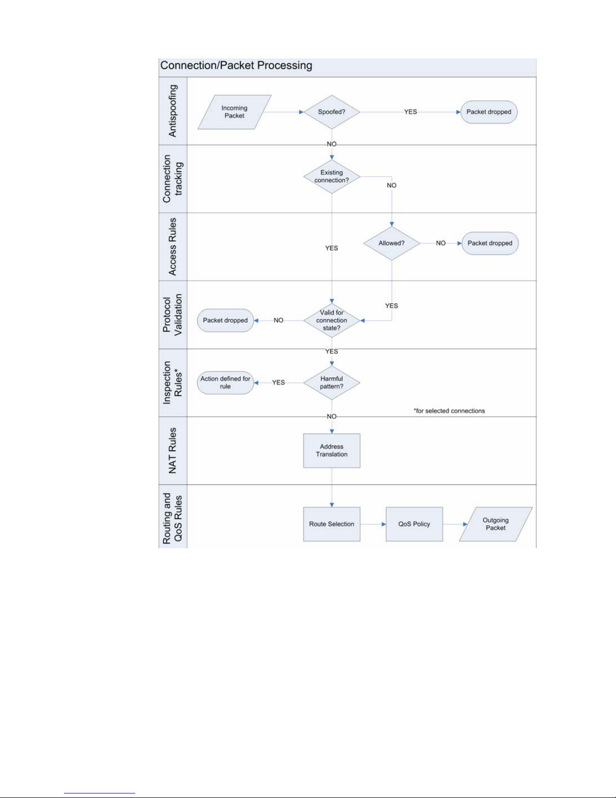
1.
2.
3.
4.
5.
6.
7.
Illustration 8.1 Connection/Packet Handling in a StoneGate Firewall
1. The firewall checks that the traffic is coming in through the correct interface as defined in
the Routing and Antispoofing trees.
2. The firewall checks the current connection tracking information to see if the packet is part
of an established connection (for example, a reply packet to a request that has been
allowed).
3. If the packet is not part of an existing connection, the packet is compared with the Access
rules in the installed Firewall Policy. The processing continues until the packet matches a
rule that tells the firewall to allow or stop the packet.
•If there is no rule match anywhere else in the policy, the packet is discarded when the
firewall reaches the end of the Firewall Policy.
Overview to Firewall Policies
71
Page 72

4. If the packet is allowed as an existing connection or in an Access rule, the firewall checks
that the packet is valid for the state of the connection. If not, the packet is dropped.
•For example, a TCP connection must always begin with a SYN packet (as defined in the
protocol standards), so the firewall checks that the first packet of a new connection is a
valid SYN packet.
5. The firewall applies Inspection rules to HTTP, HTTPS, IMAP, POP3, SIP, and SMTP
connections that are selected for deep packet inspection in the Access rules.
•Inspection applies to all packets in a connection, so the Inspection rules are applied even
if the packet is a part of an existing connection.
•The Inspection rules are used to look for harmful patterns hiding in the legitimate-looking
connections (that is, payload of packets that are a part of allowed connections).
6. Network Address Translation (NAT) rules are applied to IPv4 connections. The source and
destination addresses are translated according to the first matching NAT rule (or not done
at all, if a NAT rule so defines). If none of the NAT rules match, the packet continues with
the original addresses.
7. A routing decision is made (using the translated address), and the packet is let through
the firewall according to its priority and any bandwidth limits or guarantees that may be in
place.
Configuration of Policy Elements
There are three kinds of firewall policy elements:
• A Firewall Template Policy element is a policy that is used as the basis for Firewall Policy and
Firewall Template Policy elements. A Firewall Template Policy may contain any number of
rules. The rules in the Firewall Template Policy are copied as inherited rules into the Firewall
Policy or the Firewall Template Policy which is based on the Firewall Template Policy. You can
modify the inherited rules only by editing the original Firewall Template Policy from which the
rules were inherited.
• A Firewall Policy element gathers together all the rules from the different policy elements (the
rules added directly to the Firewall Policy, the rules from the Firewall Template Policy used as
the basis of the Firewall Policy, and possibly conditional rules from one or more Firewall SubPolicies added to the Firewall Policy). A Firewall Policy is always based on a Firewall Template
Policy element. The Firewall Policies are the only policy elements that can be installed on
firewalls.
• A Firewall Sub-Policy element is a section of rules that you can insert into Firewall Policy and
Firewall Template Policy elements. The rules in the Firewall Sub-Policy are conditional rules
that allow you to define matching criteria that determines whether the Firewall Sub-Policy
applies to a connection or not. You can modify the rules by editing the Firewall Sub-Policy
where the rules belong.
The hierarchy of how rules are inherited between different policy elements is shown in
Illustration 8.2.
72
Chapter 8 Firewall Policies
Page 73

Illustration 8.2 Rule Inheritance
Rules:
Firewall Template Policy A +
Firewall Template Policy B +
Firewall Sub-Policy + Firewall Policy
Firewall Policy
Firewall Sub-Policy
Firewall Template
Policy A
Firewall Template
Policy B
In the illustration above, Firewall Template Policy A is the basis for Firewall Template Policy B, so
Firewall Template Policy B contains all the rules defined in Firewall Template Policy A. Firewall
Template Policy B also contains all the rules in a Firewall Sub-Policy, as well as rules defined
directly in Firewall Template Policy B. The example Firewall Policy inherits the following rules:
• All the rules in Firewall Template Policy A.
• All the rules in Firewall Template Policy B.
• All the rules in the Firewall Sub-Policy.
In addition to the inherited rules, the example Firewall Policy also contains any rules that the
administrators add to it directly. In the Firewall Policy, the administrators can only edit the rules
that were added directly to the Firewall Policy. To change rules inherited from Firewall Template
Policy A, Firewall Template Policy B, or the Firewall Sub-Policy, they must edit the policy in which
the rules were originally defined.
A hierarchy such as the one outlined above is useful to
• Reduce the need for creating the same or similar rule in several policies. For example, any
rule added to Firewall Template Policy A is also added to any policy created based on that
template. The next time the Firewall Policies based on Firewall Template Policy A are installed
on firewalls, the new rule is used on all those firewalls. There is no need to modify each
individual Firewall Policy separately.
• Restrict the editing rights of administrators. For example, administrators who are granted
rights to only Firewall Policies cannot edit the rules defined in the Firewall Template Policies
on which the Firewall Policies are based. Their actions have no effect on rules that are placed
above the row where the Firewall Template Policy allows them to insert new rules. In the
hierarchy shown in the illustration above, the insert point(s) for the Firewall Policy are defined
in Firewall Template Policy B, which in turn can be edited only in the place where there is an
insert point in Firewall Template Policy A.
• Reduce the likelihood of mistakes affecting important communications. Firewall Template
Policies can be reserved for defining only the rules for essential communications, so that
most daily editing is done in the lower-level Firewall Policies. If the Firewall Template Policy is
properly designed, the rules in the Firewall Template Policy cannot be overridden by any rules
in the lower-level policy. Good organization also makes it easier to read policies, further
reducing the risk of errors.
• Improve processing performance. With the help of Firewall Sub-Policies, whole blocks of rules
may be skipped during processing when a connection does not match the rule that directs the
traffic processing to the Firewall Sub-Policy. This reduces the processor load, which may lead
to better throughput if the processor load is constantly very high.
Configuration of Policy Elements
73
Page 74

Default Elements
The following policy elements are available by default:
• The Default Template Policy contains the predefined IPv4 Access rules necessary for the
firewall to communicate with the Management Center and some external components. All
other Firewall Template Policies or Firewall Policies must be based on the Default Template
Policy or a customized copy of it. The predefined Access rules are explained in Configuration
of Access Rules (page 85).
• The Default Inspection Rules Template Policy contains the predefined Inspection rules. It is
introduced into the system when you import and activate a recent dynamic update package
(for example, during the installation).
• The DHCP Relay Sub-Policy contains rules that allow the firewall to relay DHCP requests from
a host in one internal network to a DHCP server in a different network, as well as DHCP
requests from VPN clients to an internal DHCP server.
None of the default policies can be modified. However, you can make copies of the default
policies if you need to create a modified version.
Configuration Workflow
The following sections provide an overview of the configuration tasks. Detailed step-by-step
instructions can be found in the Online Help of the Management Client and the Administrator’s
Guide PDF in the section called Policies.
Policy elements are only containers for the actual traffic handling rules. When you have decided
on a policy hierarchy, you can populate the policy elements with the actual rules for handling the
traffic (see Access Rules (page 83), Inspection Rules (page 99), and Network Address
Translation (NAT) Rules (page 109)).
Task 1: Create a Firewall Template Policy
Firewall Template Policies are used as a basis for other Firewall Policies and Firewall Template
Policies. Every Firewall Policy and Firewall Template Policy that you create is based on a Firewall
Template Policy. You can also base several policies on the same Firewall Template Policy. The
Default Template Policy or a customized copy you have created from it is always at the highest
level of the policy hierarchy. It is not mandatory to create any custom Firewall Template Policies
if you feel that it is not necessary in your environment.
When editing policies, the main difference between Firewall Template Policies and Firewall
Policies are the special rows called Insert Points. Insert points are shown in both Firewall
Template Policies and Firewall Policies, but you can add them only to Firewall Template Policies.
The Insert Points added to Firewall Template Policies mark the place where new rules can be
added to policies that are based on the templates. When creating a Firewall Template Policy, you
must add insert points separately for the Access Rules, Inspection Rules, and NAT rules.
Illustration 8.3 Insert Point in a Template Policy and the Inheriting (Template) Policy
74
Chapter 8 Firewall Policies
Page 75

Illustration 8.3 shows what the same insert point looks like in a Firewall Template Policy and in
the inheriting policy elements. The color of the insert point indicates whether the insert point
has been added in the current Firewall Template Policy for inheritance to lower levels (orange) or
whether it has been inherited from the higher-level Firewall Template Policy (green). Only the
orange insert points are inherited to lower-level policy elements, so you must add at least one
new insert point at each Firewall Template Policy level to make the lower-level policies editable.
When you add the first new rule to the green insert point, the rule replaces the insert point. Any
number of rules can then be added directly above and below that first rule.
Rules defined in the Firewall Template Policy itself are not editable in lower-level policies that
use the Firewall Template Policy. Such inherited rules are shown only on your request and they
are displayed with a grey background. Only the actual rules are inherited from a higher-level
Firewall Template Policy into the lower-level policies and Firewall Template Policies. The rights to
edit policies and Firewall Template Policies are defined separately.
Together with the editing rights, insert points help ensure that important rules are not made void
by configuration mistakes or modified by administrators who are not authorized to do so.
Because the firewall reads rules in order from the top down, any rules above the insert point in
the higher-level Firewall Template Policy cannot be cancelled by anything a lower-level policy adds
into the insert point.
Task 2: Create a Firewall Policy
A Firewall Policy is the element that gathers together all the rules from the different policy
elements: the rules inherited from the Firewall Template Policy that is used as the basis of the
Firewall Policy, rules from one or more Sub-Policies added to the Firewall Policy, and the rules
added directly to the Firewall Policy. The Firewall Policy is the only policy element that you can
transfer to a firewall. The Firewall Policy is always based on a Firewall Template Policy, either the
Default Template Policy or a Firewall Template Policy you have created.
Task 3: Create a Firewall Sub-Policy
Firewall Sub-Policies are sections of IPv4 Access rules that you can insert in the IPv4 Access
rules of Firewall Policies, Firewall Template Policies, and even other Firewall Sub-Policies to
make the firewall process traffic faster. You can also use Firewall Sub-Policies to organize rules.
The Firewall Sub-Policies are not based on any Firewall Template Policy.
The Firewall Sub-Policies may make it easier to read the policies and to assign editing rights to
administrators. For example, you can give some administrators the rights to edit only certain
Firewall Sub-Policies without giving them rights to edit Firewall Policies.
A Firewall Sub-Policy is inserted into some other policy element by adding a Jump rule to the
policy element. The Jump rule directs connections that match the Jump rule for matching
against the rules in the Firewall Sub-Policy.
Configuration of Policy Elements
75
Page 76
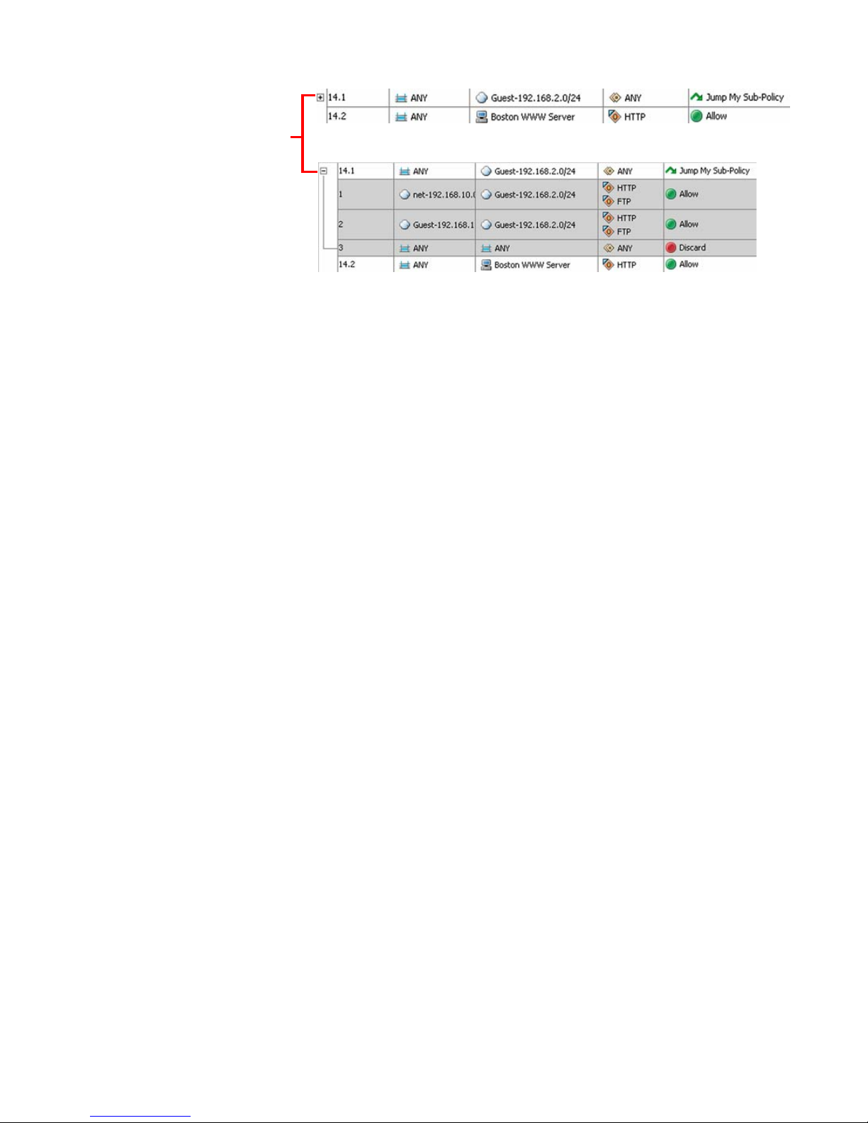
Illustration 8.4 A Firewall Sub-Policy in Use
A Jump rule inserts the
Firewall Sub-Policy, which
is shown as an
expandable section.
The illustration above shows the same Jump rule in a policy in the collapsed and the expanded
state. The rules of the Firewall Sub-Policy are shown on a grey background, because they can be
edited only within the Firewall Sub-Policy itself, not in the Firewall Policy that uses the rules.
You could use a Firewall Sub-Policy, for example, for examining traffic destined to a group of
servers located in one particular network. The Jump rule could then use the destination network
as a criteria for directing connections for matching against the Firewall Sub-Policy. Any
connection that was destined to some other network would not get matched against any of the
rules in the Firewall Sub-Policy. This makes the matching process faster, because the firewall
can skip a whole Firewall Sub-Policy by comparing a connection to just one simple rule for any
non-matching connection. If the Firewall Sub-Policy rules were inserted directly into the main
Firewall Policy, the firewall would have to compare all connections to all those rules individually
(since that is the only way to find out if the connection matches the rules or not). The
performance benefit gained depends on the number and complexity of the rules that can be
placed in a Firewall Sub-Policy and how heavily stressed the firewall is to begin with.
Task 4: Install the Policy
After creating or modifying a Firewall Policy, you must transfer the changes to the firewall using
the Management Client. You can either install the Firewall Policy (transfers the policy you select)
or refresh the Firewall Policy (transfers the most recent version of the policy that the firewall
already uses). You can install the same Firewall Policy on several firewalls.
When you install a modified or a completely new Firewall Policy, any existing connections that
are not allowed by the new Firewall Policy are dropped. The existing connections allowed by the
new Firewall Policy are not affected; they continue uninterrupted (including related connections
and authenticated connections).
Policy installation transfers any new firewall configuration information, in addition to the Firewall
Policy. Whenever you update the firewall configuration or the properties of an element used in
the configuration, you must reload the Firewall Policy on the firewall engine to make the changes
take effect. This includes, for example, changes in the routing configuration, the VPN
configuration, and the Firewall element itself, even if the changes are not directly related to the
rules in the Firewall Policy.
If the Firewall Policy installation fails, the system automatically rolls back to the previously
installed configuration. By default, a rollback also occurs if the system detects that the new
76
Firewall Policy or related configuration (such as routing configuration) does not allow the
Chapter 8 Firewall Policies
Page 77

Management Server to connect to the firewall engines. This safety feature prevents an
administrator from inadvertently installing a configuration that would cause the critical
management connections to fail.
Using Policy Elements and Rules
The main points of using policy elements are explained in the preceding sections of this chapter.
The sections below illustrates additional points that are useful to know when working with
policies and rules:
• Validating Policies (page 77)
• Connection Tracking vs. Connectionless Packet Inspection (page 77)
• Policy Snapshots (page 80)
• Continue Rules (page 80)
• Adding Comments to Rules (page 80)
Validating Policies
The number of rules in a Firewall Policy may grow quite large over time. It may become quite
difficult, for example, to spot duplicate rules in a policy. To make policy management easier and
to make sure that the policy does not contain misconfigured rules, you can automatically
validate the policy during editing as well as during the policy installation process. You can select
various criteria for validating the policy. You can, for example, check the policy for duplicate and
empty rules or check if there are rules that cannot match traffic.
Additionally, the firewall engines automatically count how many times each Access and NAT rule
has matched. You can run an analysis over a selected time frame in the policy editing view to
display rule counter hits for each rule (in the Hits cell). This allows you to find otherwise valid
rules that are unnecessary because they match traffic that does not appear in your networks.
Connection Tracking vs. Connectionless Packet Inspection
Connection tracking means that the firewall keeps a record of all currently open connections
(stateful inspection). With connection tracking, the firewall can verify that the connection
proceeds according to the protocol standards. Connection tracking is also required for modifying
addresses using NAT and enforcing some other connection-related settings. By default,
connection tracking is on.
However, it is not necessary to keep track of the state of certain kinds of connections (for
example, SNMP traps). Some applications may also communicate in a non-standard way that
prevents them from passing the firewall when connection tracking is used. For those
connections, you can disable connection tracking in the Access rules. This allows StoneGate to
function as a simple packet filter for those connections, but it also prevents you from using
some features that require the connection information from being applied to the connections.
When connection tracking is off, each packet that you want to allow must match an Access rule
allowing the packet. This means that even if two-way communications are always opened one
way, both directions of communication must be explicitly allowed in Access rules. Reply packets
are not recognized, so they are not automatically allowed through like they are when connection
Using Policy Elements and Rules
77
Page 78

tracking is on. If done carelessly, turning connection tracking off reduces the benefits you gain
from your firewall and may even weaken security. You may have other options: in some cases
using the correct Protocol Agent helps.
Note – Before disabling connection tracking, always check if there is a Protocol Agent for
the protocol in question. The Protocol Agents can pass such troublesome connections with
connection tracking on, which is always a more secure option.
When connection tracking is enabled in an Access rule, the Service cell of the rule must contain
one of the protocols supported for connection tracking (ICMP, TCP, or UDP). ICMP and UDP are
stateless protocols that do not contain any connection information. However, the ICMP and UDP
packets contain data that the firewall can use to build virtual connections. You can choose
between several connection tracking modes depending on the traffic type and how strictly you
want the connections to be tracked. The meaning of the connection tracking setting in the
Access rules depends on the traffic type. For TCP traffic, is also depends on whether Strict
Connection Tracking has been enabled in firewall properties. The available options are explained
in Table 8.1.
Table 8.1 Connection Tracking Modes
Mode Protocol Explanation
Default
Normal
TCP
ICMP and
UDP
ICMP
TCP
UDP
Traffic is handled as in the Normal mode or Strict mode depending on
whether Strict Connection Tracking has been enabled in the firewall
properties. See below for more information.
Traffic is handled as in the Normal mode (see below).
This is the recommended mode for ICMP. The firewall drops packets that refer
to non-existing connection tracking entries if the packets are not allowed by
another rule in the policy.
This is the recommended mode for TCP. The firewall checks that the traffic
proceeds according to the TCP protocol (that a valid, complete TCP
handshake is performed). If the Service cell in the rule contains a Service
that uses a Protocol Agent, the firewall also validates the traffic on the
application layer. If a protocol violation occurs, the connection is dropped.
This is the recommended mode for UDP. The firewall checks the traffic
direction and the port parameters used in the communications. The traffic
itself is not checked by default. If the Service cell in the rule contains a
Service that uses a Protocol Agent, the firewall also validates the traffic on
the application layer.
78
Chapter 8 Firewall Policies
Page 79

Table 8.1 Connection Tracking Modes (Continued)
Mode Protocol Explanation
This mode can be used if you only want to allow TCP traffic that strictly
adheres to TCP as defined in RFC 793. Other TCP traffic, for example,
Transactional TCP traffic, is not allowed (see RFC 1644).
The firewall checks that the TCP handshake proceeds according to the TCP
Strict TCP
ICMP
TCP
Loose
definition. It also checks the sequence numbers of the packets in preconnection establishment states and for RST and FIN packets, and drops the
packets that are out of sequence. If the Service cell in the rule contains a
Service that uses a Protocol Agent, the firewall also validates the traffic on
the application layer. If a protocol violation occurs, the connection is
dropped.
You can use this mode in special cases when you want to use connection
tracking for virtual ICMP connections that would not be allowed in the Normal
mode (for example, to allow ICMP echo requests and replies).
The firewall allows packets that refer to non-existing connection tracking
entries to pass.
You can use this mode to allow connections or to enable NAT in special
cases (for example, if routing is asymmetric or dynamic routing protocols are
used).
The firewall accepts connections that begin with any kind of packet. It allows
packets belonging to traffic that has expired in connection tracking to
continue. In this mode, only static NAT is supported (but not with Multi-Link).
You can use this mode in special cases when you want to use NAT with
virtual UDP connections that would not be allowed in the Normal mode.
Only NAT is affected. If the connection tracking mode was Loose when an old
UDP
NAT entry was generated and the entry is in conflict with a new NAT entry, the
new entry replaces the old one. In addition, if an engine detects that a Server
Pool member or an ISP has gone down, the NAT entries for the virtual
connection are cleared and a new NAT entry is made when the next packet
arrives.
If connection tracking is on, you can also set the Idle Timeout for connections. The timeout is
meant for clearing the firewall’s records of old connections that the communicating hosts leave
hanging. The timeout concerns only idle connections, so connections are not cut because of
timeouts while the hosts are still communicating. The timeout defined for an Access rule
overrides the default idle timeout value that is set for the protocol in question in the Firewall
element’s properties.
Caution – Setting excessively long timeouts for many connections can consume resources
to a point where the firewall performance and stability start to suffer. Be especially careful
when defining timeouts for ICMP and UDP. The ICMP and UDP virtual connections do not
have closing packets, so the firewall keeps the records for the ICMP and UDP connections
until the end of the timeout.
Connection tracking also allows you to set a hard limit to concurrent connections from a single
source and/or destination IP address. When the set number of connections is reached, the next
connection attempts are blocked by the firewall until a previously open connection is closed.
Using Policy Elements and Rules
79
Page 80

Changes in the connection tracking mode affect how existing connections are handled at policy
installation. When you upload a policy on an engine, the firewall checks if the existing
connections are still allowed in the policy. If the connection tracking mode changes from Loose
to Strict, existing virtual ICMP connections are only allowed if they began with a valid packet (for
example, not with a response packet). Also, if the mode changes from Normal to Strict, existing
TCP connections are only allowed if all the packets in the connection have been seen. In all
other cases, changes in connection tracking mode do not affect existing ICMP, TCP, and UDP
connections at policy installation.
Policy Snapshots
A Policy Snapshot is a stored record of a policy configuration. A policy snapshot is stored in an
engine’s upload history whenever a policy is installed or refreshed on the engine. The Policy
Snapshots allow you to the check which Firewall Policies and other configuration information
were uploaded, and when they were uploaded. You can also compare any two policy snapshots
and see the differences between them highlighted.
Continue Rules
The Continue action for a rule sets default options (such as logging options, idle timeout, etc.)
for the traffic matching process. Options set in Continue rules are used for subsequent rules
that match the same criteria as the Continue rule, unless the rules are specifically set to
override the options. Continue rules are also very useful in the hierarchical structure of the
policies. Firewall Template Policies are particularly convenient for setting options with a
Continue rule, because all the Firewall Policies and Firewall Template Policies that use the
Firewall Template Policy inherit the option settings you have specified. Continue rules are
explained in detail in Configuring Default Settings for Several Rules (page 94).
Adding Comments to Rules
Each policy can contain a large number of rules. Adding comments provides administrators with
useful information and also makes it easier to read policies. You can add comments to all types
of rules. You can add comments in the rule’s Comment cell or add dedicated Comment Rule
rows between rules. When you add a Comment rule, a new section is added to the policy. The
new section automatically contains all the rules below the Comment Rule until the next
Comment Rule in the policy. You can expand and collapse the sections as necessary. The
Comment rules are displayed on a colored background, so they are particularly good for visually
separating sections of rules within a single policy.
80
Chapter 8 Firewall Policies
Page 81

Examples of Policy Element Use
The examples in this section illustrate some common uses for the different policy elements in
StoneGate and general steps on how each scenario is configured.
Protecting Essential Communications
Company A has a firewall system administered by multiple administrators of various degrees of
familiarity with networking, firewalls, and StoneGate. The administrators must often make very
quick changes to respond to the needs of the company and attend to any problems detected.
In this situation, it is possible that someone may accidentally alter the Firewall Policy in such a
way that important services are cut off. The administrators decide to separate the rules allowing
the most important business communications from rules that deal with non-essential traffic to
minimize this risk. The administrators:
1. Create a new Firewall Template Policy under the Default Template Policy.
2. Cut and paste the rules allowing essential communications from their current Firewall
Policy into the new Firewall Template Policy.
•In this case, all administrators are allowed to edit the new Firewall Template Policy as
well.
3. Add an insert point below the copied rules in the Firewall Template Policy.
•Having the insert point below the essential rules prevents the rules added to the
inheriting Firewall Policy from affecting the essential communications.
4. Reparent their current Firewall Policy to use the new template, moving it down a step in
the policy hierarchy.
5. After validating the policy and making sure that the rules are correct, refresh the current
Firewall Policy.
•Since most daily editing is done in the Firewall Policy, there is less risk of someone
accidentally changing the essential rules in the Firewall Template Policy, because the
rules are not editable in the Firewall Policy.
Improving Readability and Performance
Company B has two separate DMZs, one for the extranet and one for other Web services. The
number of services offered is quite large. The company also has a large number of partners and
customers that have varying access rights to the different services. The administrators realize
that a large number of the rules in their policies are related to the DMZ connections. The rest of
the rules govern access to and from the company’s internal networks. Many of the rules have
been entered over time by inserting them at the beginning of the rule table, so rules governing
access to the different networks are mixed and finding all the rules that govern access to a
particular network takes time.
Examples of Policy Element Use
81
Page 82

The administrators decide that they want to make their Firewall Policy more readable and at the
same time optimize the way the firewall handles traffic, so they:
1. Create two new Firewall Sub-Policies: one for each DMZ.
2. Cut-and-paste the rules from the current Firewall Policy into the correct Firewall SubPolicies.
3. Add Jump rules into the Firewall Policy to direct the examination of traffic to/from the
different networks into the correct Firewall Sub-Policy.
4. Refresh the Firewall Policy.
Restricting Administrator Editing Rights
Company C is implementing a distributed network with multiple sites: one central office where
most of the StoneGate administrators work, and a number of branch offices in different
countries. The branch offices mostly have IT staff with only limited networking experience, but
who are still responsible for the day-to-day maintenance of the network infrastructure at their
site. They must be able to, for example, add and remove Access rules for testing purposes
without always contacting the main StoneGate administrators.
The StoneGate administrators decide to limit the privileges of the branch office IT staff so that
they are not able to edit the policies of the firewalls at any of the other sites. The
administrators:
1. Create a new Firewall Template Policy based on the Default Template Policy.
2. Add rules to the Firewall Template Policy using Alias elements to cover the essential
services that each of these sites has, such as the VPN connections to the central site.
•Using a common Firewall Template Policy for all the branch offices also eliminates the
need to make the same changes in several policies, easing the workload.
3. Create a new Firewall Policy based on the new Firewall Template Policy for each of the
branch office sites.
•Although a single Firewall Policy for all sites could work, in this case the administrators
decide against it, since separate policies are needed for the separation of editing rights.
The policies are based on the same Firewall Template Policy, so rules can still be shared
without duplicating them manually.
4. Grant each Firewall Policy to the correct Firewall element.
•After this, only the correct policy can be installed on each firewall. No other policy is
accepted.
5. Create new administrator accounts with restricted rights for the branch office
administrators and grant the correct Firewall element and Firewall Policy to each
administrator.
•The branch office administrators are now restricted to editing one Firewall Policy and can
install it on the correct firewall.
•The branch office administrators are not allowed to edit the Firewall Template Policy the
policy is based on, nor can they install any other policies on any other firewalls.
For detailed information on administrator rights, see the Management Center Reference Guide.
82
Chapter 8 Firewall Policies
Page 83

CHAPTER 9
ACCESS RULES
Access rules are lists of matching criteria and actions that define how the firewall treats
different types of network traffic. They are your main configuration tool for defining which
traffic is stopped and which traffic is allowed.
The following sections are included:
Overview to Access Rules (page 84)
Configuration of Access Rules (page 85)
Using Access Rules (page 93)
Examples of Access Rules (page 96)
83
Page 84

Overview to Access Rules
The IPv4 and IPv6 Access rules are traffic handling rules in which you define the details of how
you want the traffic to be examined and which action you want to take when matching details are
found. The Access rules are stored in policy elements, which are discussed in Firewall Policies
(page 69).
The traffic matching is based on the information contained in the packets:
• Source and destination IP addresses.
• Protocol-specific information, such as the port information for protocols that use ports.
Additional matching criteria that is not based on information in the packets includes:
• (IPv4 only) The VPN where the traffic is coming from (on an engine where that VPN
terminates). This allows creating rules that apply to VPN traffic only, or rules that apply to all
traffic except VPN traffic.
• (IPv4 only) User authentication (allowing you to create rules that define the end-users who are
allowed to make connections and the authentication methods for the end-users).
• The day of the week and the time of day (allowing you to enforce rules only during certain
times, such as working hours).
The Access rules provide several different ways to react when some traffic is found to match a
rule. You can:
• Specifically allow the traffic.
• Specifically stop the traffic.
• (IPv4 only) Allow the traffic on the condition that the user has passed authentication.
• (IPv4 only) Allow the traffic on the condition that a VPN is established.
• Allow the traffic on the condition that the same source and/or destination IP address does
not have an excessive number of connections already open (concurrent connection limit).
Regardless of which of the above actions is taken, a matching rule can also create a log or alert
entry.
Additionally, Access rules select which allowed traffic is subjected to further inspection against
the Inspection rules.
In addition to traffic allowed by the Access rules, StoneGate automatically allows the following
types of traffic with specific configurations:
• DHCP requests and replies for an interface for which a DHCP server is enabled.
• DHCP requests and replies for an interface that has a dynamic IP address.
• State synchronization between cluster nodes.
• IPv6 Neighbor Discovery traffic.
84
Chapter 9 Access Rules
Page 85

Configuration of Access Rules
Mandatory cells for
matching traffic
Firewall applies Action
when it finds a match
Network
El
e
m
e
nts
Proto
c
o
l
Ser
v
ices
Users
(IPv
4
on
ly
)
U
s
er
Grou
ps
(
IPv4 only
)
Au
the
nticati
o
n
S
e
rv
i
ces (
I
Pv4
o
nl
y
)
QoS
C
l
a
ss
VP
N
(I
Pv4
on
ly)
IPv4 Access rules are configured on the IPv4 Access tab, and IPv6 Access rules are configured
on the IPv6 Access tab inside Firewall Policy and Template Policy elements. IPv4 Access Rules
can additionally configured in Sub-Policy elements. You can create new Access rules in the Policy
Editing View. You can also create Access rules in the Logs view based on one or more selected
log entries (not available for IPv6 Access rules).
Illustration 9.1 Newly Inserted IPv4 Access Rule - Main Cells
Illustration 9.1 above displays an Access rule that has just been inserted into the policy. The
matching cells are set to <None> and the action is set to Discard, to prevent the rule from
having any effect on traffic in case a new rule is added to the policy accidentally. It is not
necessary to modify all cells in each rule, but the mandatory cells for traffic matching (Source,
Destination, and Protocol) must be set to some value other than <None> for the rule to be
valid. The Source VPN cell (IPv4 only) is also matched against traffic in the inspection process,
but it can be left empty to match all traffic. The other editable cells specify further conditions
and options, such as logging.
Before starting to build policies, make sure you understand the network element types available
and how you can use them efficiently to define the resources that you want to protect and
control. The illustration below shows the types of elements that you can use in Access rules.
Illustration 9.2 Elements in Access Rules
Configuration of Access Rules
85
Page 86

The table below explains briefly what each Access rule cell does and which elements you can
use in the rules. The cells are presented in the default order, but you can drag and drop them to
your preferred order in your own Management Client.
Table 9.1 Access Rule Cells
Cell Explanation
(Not editable) Automatically assigned ID number that indicates the order of the
ID
Source Elements containing the IP addresses that the rule matches. Both the Source and
Destination
Service
rules in the policy. The rules are matched against traffic in the order of the ID
numbers. For example, the rule 14.3 is the third rule added in this policy to the
insert point that is the fourteenth rule in the upper-level template.
the Destination defined must match the source and destination of a packet for the
packet to match the rule. The Source and Destination cells accept any elements in
the Network Elements category. Network Elements used in IPv4 Access Rules must
contain IPv4 addresses, and Network Elements used in IPv6 Access Rules must
contain IPv6 addresses.
Services match a certain port, but they often also reference a Protocol for more
advanced, application-layer inspection and traffic handling. The Service cell accepts
Service and Service Group elements.
Action
Users
Authentication
QoS Class
Logging
Time
Comment
Command for the firewall to carry out when a connection matches the rule, and
options for connection tracking, deep inspection (IPv4 only), anti-virus (IPv4 only),
blacklisting (IPv4 only), and VPN connections (IPv4 only).
(IPv4 only) The end-users that the rule applies to when the rule requires
authentication. This cell accepts both User and User Group elements.
(IPv4 only) Defines whether the rule requires end-users to authenticate and the
authentication methods (Authentication Services) that are valid for this rule.
The QoS Class that the firewall assigns to connections that match this rule. Used in
traffic prioritization and bandwidth management. The QoS Class has effect only if
you set up QoS Policies, see Bandwidth Management And Traffic Prioritization
(page 199).
The options for logging when traffic matches the rule. If no options are specified,
the behavior is as explained in Task 4: Select Logging Options (page 92).
The time period when the rule is applied. If this cell is left empty, the rule applies at
all times.
Your optional free-form comment for this rule. If you add a rule from the Logs view,
the Comment cell of the rule automatically includes information on the log entry
which was used as the basis of the rule. You can also add separate comment rows
in between rules.
(Not editable) Automatically assigned unique identifier for the rule. Works as a link
between the log entries and the rule that has generated the log entries. The rule
Tag
86
Chapter 9 Access Rules
tag consists of two parts (for example, @180.2). The first part of the tag is
permanent and belongs to only that rule. The second part changes when the rule is
changed. The first part and the second part are separated by a period.
Page 87

Table 9.1 Access Rule Cells (Continued)
Cell Explanation
(IPv4 only) Makes the rule match traffic based on whether it is coming from a
Source VPN
Hit
specific VPN. If this cell is left empty, the rule matches both VPN and non-VPN
traffic.
(Not editable) Shows the number of connections that have matched the rule. This
information is only shown if you have run a Rule Counter Analysis for the policy. The
cell shows “N/A” if there is no information available about the rule.
Considerations for Designing Access Rules
One of the crucial issues in designing policies is the order of the rules. The most important
thing to keep in mind when editing Policies is that the rules are read from top down. The actions
Allow, Refuse, and Discard and the action Use IPsec VPN (IPv4 Access rules only) with the
option Enforce stop the processing from continuing down the rule table for any connection that
matches the rule. Therefore, rules with any of these actions must be placed so that the more
limited the rule is in scope, the higher up in the rule table it is.
Example An Access rule that allows connections to the IP address 192.168.10.200 must be put above
an Access rule that stops all connections to the network 192.168.10.0/24.
Default Elements
There is a template called Default that contains the basic Access rules that allow
communications between the StoneGate firewall on which the policy is installed and other
system components.
You must use the Default template as the basis for defining your own templates and policies, as
it is not possible to create a new template at the highest level of the policy hierarchy. No
changes can be made directly to the Default template, but you can create your own copy of it if
you have a specific need to modify those rules.
Note – If you use a copy of the Default template, you may have to adjust your rules
manually when the system is upgraded to account for changes in system communications.
Upgrades can change only the Default template, not the copies.
Configuration of Access Rules
87
Page 88

Illustration 9.3 Default Template Access Rules
The illustration above shows the IPv4 Access rules included in the Default template. The insert
point, where rules can be added in the inheriting Policy and Template Policy elements, is shown
as a blank row near the end of the rule table.
The rules above the insert point detail the various kinds of system communications. Most of the
IP addresses are defined using Aliases to make the rules applicable on any system where they
are installed. These Aliases are default elements in the system and they are listed in the
appendix Predefined Aliases (page 269). The Service cell is the best starting point for
understanding in greater detail what these rules do. See appendix Default Communication Ports
(page 261) for a listing of the system communications and the Service elements that
correspond to them.
There are two rules below the insert point. The rule directly below the insert point has the action
Refuse for the Ident protocol traffic, which means that this traffic is stopped with an ICMP error
message sent to the Ident request sender. This rule exists to prevent Ident requests from being
silently dropped (as the next rule specifies for all other traffic), because silently dropping Ident
requests causes delays in communications. The last rule before the end of the policy is a rule
that discards all traffic and creates a log entry that is stored. This rule’s purpose is to ensure
that this connection dropping is logged, since the firewall silently drops the connection without
creating a log entry if the matching process reaches the end of the policy.
88
Chapter 9 Access Rules
Page 89

Illustration 9.4 Default Template IPv6 Access Rules
The illustration above shows the IPv6 Access rules included in the Default template. The insert
point, where rules can be added in the inheriting Policy and Template Policy elements, is shown
as a blank row near the end of the rule table.
Configuration Workflow
The following sections provide an overview of the configuration tasks. Detailed step-by-step
instructions can be found in the Online Help of the Management Client and the Administrator’s
Guide PDF, in the section called Policies.
Task 1: Define the Source and Destination
The Source and Destination cells specify the IP addresses that are compared to the IP
addresses in each packet’s header. Based on these and other criteria, the rule is applied to
matching packets.
You can add more than one element in each cell. Groups, Aliases, Address Ranges, and
Expressions are especially useful for defining IP addresses in complex scenarios. You can set
these cells to ANY to make the rule match all possible source or destination IP addresses.
Task 2: Define the Service
The Service cell defines the protocol(s) that are compared to the protocol-related information in
each packet’s header. By default, the Service is set to <None>, and you must change the value
to make the rule valid.
The Service cell accepts only Service and Service Group elements. There are ready-made
Services in the system that cover most needs, but you may also use your own customized
versions, for example, to define a non-standard port. The Services available for rule design are
categorized according to protocols. You can add more than one element in this cell to make the
rule match several Services.
Configuration of Access Rules
89
Page 90

Certain Services are associated with Protocols of the Protocol Agent type, which define more
advanced inspection and handling for the connections. Additionally, the Protocol element
identifies the protocol for the traffic for inspection against the Inspection rules (only some
protocols are supported for this purpose on the firewall). For more information on Protocols and
the network protocols that require Protocols of the type Agent, see Protocol Agents (page 123).
You can set the Service to ANY to make the rule match traffic using any protocol. A previous
Continue rule (such as the one in the Default template) may define a Protocol of the Protocol
Agent type for certain types of traffic that is allowed by rules with ANY as the Service (see
Configuring Default Settings for Several Rules (page 94)). If there is no previous Continue rule
matching the same connection that would define a Protocol of the Protocol Agent type, a rule
allowing ANY Service does not apply a Protocol of the Protocol Agent type to the traffic.
Note – The firewall cannot handle some types of traffic correctly if the traffic is allowed
without the correct Protocol of the Protocol Agent type when connection tracking is on
(stateful inspection).
Task 3: Select the Action and Action Options
The Action cell defines what happens when a packet matches the rule. The Action Options
define additional action-specific options for connection tracking, deep inspection, anti-virus, and
blacklisting (IPv4 only). If no options are specified, the Action Option settings from the previous
Continue rule are applied.
The available actions are explained in Table 9.2.
Table 9.2 Action Field Options
Action Explanation
Allow The connection is let through the firewall.
Stores the contents of the Options and QoS Class cells and the
Protocol (if defined in the Service used) in memory and continues
Continue
Discard The connection is silently dropped.
Refuse
Jump
the inspection process. Used for setting options for subsequent
rules as explained in Configuring Default Settings for Several Rules
(page 94).
The connection is dropped and an ICMP error message is sent in
response to notify the packet’s sender.
Matching is continued in the specified sub-policy until a match is
found. If there is no matching rule in the sub-policy, the process is
resumed in the main policy.
90
Chapter 9 Access Rules
Page 91

Table 9.2 Action Field Options (Continued)
Action Explanation
Enforce
Apply
IPsec VPN
(IPv4 only)
Apply Blacklist (IPv4 only)
Forward
The Selected
IPsec VPN
$ Client-toGateway IPsec
VPNs
The connection is allowed if the specified VPN is used. Otherwise
the connection is discarded.
The connection is allowed if the specified VPN is used. Otherwise,
the rule is considered as non-matching and the matching process
continues to the next rule.
The connection is forwarded from one VPN to another. For more
information, see VPN Configuration (page 221).
Specifies a gateway-to-gateway or a client-to-gateway IPsec VPN.
Specifies any client-to-gateway IPsec VPNs.
Checks the packet against the blacklist according to the options
set for this rule. If the packet matches a blacklist entry, the
connection is discarded.
The available action options are explained in Table 9.3.
Table 9.3 Action Options
Action Option Explanation
Define whether the firewall keeps a record of the currently open
Connection Tracking
Deep Inspection
Anti-Virus
Blacklisting (IPv4 only)
connections (stateful inspection). See Connection Tracking vs.
Connectionless Packet Inspection (page 77) for more information. Used by
rules with the Allow, Continue, or Jump action.
Defines whether matching connections are inspected also against the
Inspection rules. Used by rules with the Allow, Continue, or Jump action.
Defines whether HTTP, HTTPS, IMAP, POP3, or SMTP traffic is inspected
against a virus signature database on StoneGate UTM appliances. By
default, the Antivirus options are undefined, which means that the rule
uses anti-virus options set in the previous matching Continue rule above.
See Virus Scanning (page 157) for more information on configuring virus
scanning for UTM appliances. Used by rules with the Allow, Continue, or
Jump action.
Define which entries on the blacklist apply to connections that match the
rule based on the component that added the blacklist entry on the
blacklist. A restriction based on blacklist sender may be necessary, for
example, if the same IP address exists in two different networks. The
default setting is to take all blacklist entries into account regardless of the
component that created the entry. Used by rules with the Apply Blacklist
action.
Configuration of Access Rules
91
Page 92
Task 4: Select Logging Options
By default, the rule’s Logging options are undefined, which means that the rule uses logging
options that have been set in the previous Continue rule above. If there is no previous Continue
rule, a Stored-type log entry is created. Logging for the closing of the connection can be turned
on or off, or on with accounting information. You must collect accounting information if you want
to create reports that are based on traffic volumes.
The log levels are explained in Table 9.4.
Table 9.4 Log Levels in Access Rules
Log Level Explanation
Alert An alert entry is generated.
Stored A log entry is generated and stored on the Log Server.
When the Log Server is unavailable, log entries are temporarily stored on the Firewall
Essential
Transient A log entry is only available for immediate display in the Logs view and is not stored.
None The rule does not produce any log entries.
engine. When the Firewall engine is running out of space to store the log entries, it
begins discarding log data in order of importance.
Task 5: Add User Authentication
(IPv4 only) The firewall can enforce user authentication. A client-to-gateway VPN always requires
some form of authentication, but you can also add the authentication requirement to non-VPN
rules if you wish. For more information, see User Authentication (page 133).
The authentication is configured in the Users and Authentication cells. The Users cell accepts
User and User Group elements and defines the end-users who are allowed to make connections
allowed by the rule. You define the authentication method used in this particular rule in the
Authentication cell, as each user and user group can have several authentication methods
configured.
If the authentication fails, the connection is discarded. If the authentication succeeds, the
connection is allowed through.
Task 6: Restrict the Time When the Rule Is Enforced
Optionally, you can set a specific time period when a rule is applied using the Time cell. The
validity of the rule can be set by month, day of the week, and time of day. For example, you might
have certain rules that allow access only during business hours on weekdays. If you leave the
Time cell empty, the rule is always valid.
Note – The times are entered in Coordinated Universal Time (UTC), and you must adjust
the times you enter to make them correspond to the firewall’s local time zone. Also
consider that UTC time does not adjust to daylight saving time (summer time).
92
Chapter 9 Access Rules
Page 93

Task 7: Restrict the Rule Match Based on Source VPN
(IPv4 only) Optionally, you can match the rule based on whether the traffic is coming from a VPN.
You can define that the rule matches only non-VPN traffic, or only traffic from a certain VPN. For
more information, see Overview to VPNs (page 213).
Using Access Rules
The general configuration of Access rules is explained above. The sections below provide further
information on configuring Access rules:
• Allowing System Communications (page 93)
• Configuring Default Settings for Several Rules (page 94)
• Using Aliases in Access Rules (page 95)
For general information on using rules, see Using Policy Elements and Rules (page 77).
Allowing System Communications
The necessary communications between the firewall and other StoneGate components are
allowed in the Default Template Policy. However, the Default template does not allow other
StoneGate components to communicate through the firewall to some third StoneGate
component.
For example, in a configuration where you have a firewall and a Log Server at a remote site that
are managed by a Management Server behind a firewall at a central site, you must create rules
in the Firewall Policy at the central site to allow:
• Management and monitoring connections to/from the remote firewall.
• Monitoring and log browsing connections from the central site to the remote Log Server.
• Any remote-site Management Client connections to the Management Server at the central
site.
If NAT is applied to the connections, Access rules alone are not enough. You must also create
Location elements and add Contact Addresses for the elements to define which translated
addresses are necessary for making contact (see NAT and System Communications
(page 116)).
There are predefined Service elements in the system for all system communications. You can
use these to create Access rules. See Default Communication Ports (page 261) for more
information on system communications.
Using Access Rules
93
Page 94

Configuring Default Settings for Several Rules
You may want to set default values for some settings in rules to avoid defining the same
settings for several rules individually. The Continue action is used to set such default values.
When a connection matches a rule with Continue as the action, some of the rule’s settings are
written in memory but the matching continues until another rule that matches is found. This
matching rule uses the defaults set in the Continue rule unless the rule specifically overrides
the defaults with different settings. This way, you do not have to define the settings for each rule
separately. You can use Continue rules to set default settings for a general type of traffic and
define settings for individual rules only when specifically required. There are also default values
that are used for rules that are set to use the values of a Continue rule, but there is no previous
matching Continue rule.
The options that can be set using Continue rules in Access rules include:
• The Connection Tracking option (default is on), including its sub-options:
•The Idle Time-out (overrides also the global defaults set in the Firewall element’s
properties).
•The concurrent connection limits set per single source and/or destination IP address.
• The logging options (default is Stored).
• The Protocol inside the Service (used to apply a Protocol to rules with ANY as their Service,
see Using Continue Rules to set the Protocol (page 95)).
• The QoS Class (default is that no specific QoS Class is assigned).
Continue rules are defined the same way as other rules. However, you must keep in mind that
when any of the options listed above is set in the Continue rule, many or even all rules below
may be affected. The Continue rule options are used by the rules below, provided that the
Source, Destination, Service, and the optional Source VPN definition match the same
connection as the Continue rule. Continue rules are inherited from Template Policies into lowerlevel templates and policies like any other rules.
Continue rules behave in the same way as any other rules. A Continue rule can be overridden by
some subsequent Continue rule that has an identical scope (Source, Destination, etc.), or
partially overridden by a Continue rule that partially overlaps with the previous Continue rule.
When you define Continue rules with different matching criteria, you can have several Continue
rules one after another without them interfering with each other in any way at all.
Sub-Policies may require special attention with Continue rules: the Sub-Policies may have
different options when you insert them into different policies if the Sub-Policy rules do not
override the options set by preceding Continue rules. Also, when a Sub-Policy contains a
Continue rule, the options are then used for further matching in the higher-level policy (if the
processing returns to the higher-level policy).
Using Continue Rules to Set Logging Options
One common use for the Continue action is to set the default log level for all subsequent rules.
Instead of setting the logging option for all rules individually, you can set a Continue rule in a
template or in a policy to set the default log level. The logging level for any subsequent matching
rules can be left undefined, yet they trigger logging as defined in the Continue rule.
94
Chapter 9 Access Rules
Page 95

Illustration 9.5 Setting the Default Log Level
In Illustration 9.5, the default log level is set to Transient for any source, destination or service.
All subsequent rules in this policy and any sub-policies log Transient by default. In this way, the
administrator can collect information to display in the Logs view for all rules. Individual rules can
still override this option with specific log levels, such as Essential or Stored.
There is also a default logging setting that is used if logging is not defined for a rule and there is
no prior Continue rule that would determine its logging mode: an Access rule will generate a
Stored log entry in that case.
Using Continue Rules to set the Protocol
The default Protocol can be set using the Continue action. This way, the correct Protocol is also
used for traffic that is allowed by rules that are set to match any Service (this may be even be
mandatory, for example, if you want to allow certain protocols that allocate ports dynamically).
The Default template includes one Continue rule that defines that Protocols of the type Agent
are used for the Service Group Default Services with Agents.
Illustration 9.6 Default Template Protocol Agent Rule
If you want to set a Protocol for more types of protocols or override the Default rule shown in
Illustration 9.6 for some or all connections, place one or more Continue rules at the top or some
other suitable place in your own template or policy. The Source and Destination can be some
specific addresses if you want to limit the scope of your Continue rules.
For more information on using Protocols of the type Agent in rules, see Protocol Agents
(page 123).
Using Aliases in Access Rules
Aliases are one of the most useful tools for reducing the complexity of a policy. With Aliases, you
can avoid creating multiple, near-duplicate rule sets when you have several firewalls. The Alias
element is used like any other network element. However, the IP addresses that the Alias
represents depends on the Firewall where the rules are installed. The IP address to firewall
mapping is defined in the Alias element.
For example, in a company that has offices in several different locations, each office can have
its own Web server. The Web server rules could be put in a single Sub-Policy, but each location’s
Web server has a different IP address. Normal rules would require allowing access to all IP
addresses on all firewalls, which is not only unnecessary, but can also be considered a security
risk. Using Aliases, the company can create a single set of rules that are still valid when applied
to multiple firewalls, but which do not allow access to IP addresses that are not in use on a
particular firewall.
In this way, Aliases simplify policies without reducing security.
Using Access Rules
95
Page 96

Examples of Access Rules
Administrators
Internet
FTP Server
WWW Servers
Authenticating
Users
Internal
Network
The examples in this section illustrate some common uses for Access rules and general steps
on how each scenario is configured.
Example of Rule Order
Company A has an office network, a DMZ for WWW servers, and a second DMZ for an FTP
server. At this point, the administrators only need to add rules for the DMZ traffic.
Illustration 9.7 Company A’s Communications of Special Interest
The WWW servers must be accessible to anyone from both internal and external networks. HTTP
traffic will be inspected against the Inspection rules, excluding the administrators’ own PCs (on
the right in the illustration), since they often test the servers for vulnerabilities. The FTP server
is accessible to all users in the general office network, but only to certain external users (on the
left in the illustration) that authenticate using an external authentication server.
The administrators:
1. Create Host elements for the WWW servers, the FTP server, and the administrators’ PCs.
2. Create a Group element that contains the WWW server Host elements.
3. Create a Group element that contains the administrator PCs’ Host elements.
4. Configure an external authentication server for use with StoneGate.
5. Create User and User Group elements for the allowed external FTP users.
96
Chapter 9 Access Rules
Page 97

6. Add IPv4 Access rules with the Allow action for access to the DMZs:
Table 9.5 Access Rules for the DMZ
Source Destination Service Users Authentication Action
“Administrator
PCs” Group
ANY
Network element
for Office
Network
ANY
•As seen in the rule table, there are two rules for traffic to both the WWW servers and the
•The rules are arranged so that the more specific rules are above the more general rules.
•If the first two rules were in the opposite order, the rule specific to administrators would
“WWW Servers”
Group
“WWW Servers”
Group
“FTP Server”
Host
“FTP Server”
Host
“HTTP” Service
“HTTP” Service
“FTP” Service
“FTP” Service
“External
Users”
User Group
Require
authentication with
the external
authentication
service selected
Allow (Deep
Inspection Off)
Allow (Deep
Inspection Off)
Allow (Deep
Inspection Off)
Allow (Deep
Inspection Off)
FTP server.
For example, the rule allowing administrators to connect to the WWW servers without
checking against the Inspection rules is above the more general rule that allows any
connection to the servers as subject to the Inspection rules.
never match, as the rule with the source as ANY would be applied first, the connection
would be allowed according to that general rule, and the firewall would stop checking the
rule table.
Examples of Access Rules
97
Page 98

Example of Continue Rules
Company B has decided to implement QoS Policies. The administrators want to set the QoS
Class for traffic using a classification of high, medium, and low for all traffic depending on the
sender. High priority is assigned to a small number of hosts in different networks, medium
priority to one internal network, and low priority to all other hosts. The administrators want to
follow how much traffic is allowed using the highest priority, so they also want to make sure that
this traffic is logged with the accounting option turned on. They decide that the lower priorities of
traffic need not be permanently logged at this point, so the administrators:
1. Configure the QoS features.
2. Create elements for all high-priority hosts.
3. Add the following Access rules to the top of their policy:
Table 9.6 Continue Rules for Logging and QoS Class
Source Destination Service Action Logging QoS Class
Important Hosts ANY ANY Continue
Network element
for Important
Network
All other Hosts ANY ANY Continue Transient Low priority
ANY ANY Continue Transient Medium priority
Stored with
accounting
High priority
•After adding these rules, individual rules can override the settings as needed, but most of
the existing rules governing access from internal networks to the Internet now use the
QoS Class and Logging options as set in these rules.
4. Transfer the policy to the firewall.
98
Chapter 9 Access Rules
Page 99

CHAPTER 10
INSPECTION RULES
Inspection rules define how the firewall looks for malicious patterns in traffic allowed through
the Access rules and what happens when a certain type of pattern is found.
The following sections are included:
Overview to Inspection Rules (page 100)
Configuration of Inspection Rules (page 101)
Using Inspection Rules (page 106)
Example of Inspection Rules (page 107)
99
Page 100

Overview to Inspection Rules
Inspection rules define how the main traffic analysis is done for traffic that has been allowed
and selected for inspection in the Access rules. The Inspection rules are stored in policy
elements, which are discussed in Firewall Policies (page 69).
Inspection rules examine the entire contents of the packets throughout whole connections to
see if the data being transferred contains a pattern of interest. The main source of these
patterns are the dynamic update packages that Stonesoft releases, but you can also define new
patterns as Situation elements, which are discussed in Situations (page 169). Using the
inspection capabilities on the firewall requires enough hardware resources available to support
the feature, as the inspection process is memory-intensive.
There are three general types of cases for using Inspection rules:
• You can detect attempts to exploit known vulnerabilities in your systems and prevent such
attempts from succeeding if the system is not patched against it.
• You can monitor traffic that does not cause alarm on the surface, but when examined for
certain patterns, may turn out to conceal actual threats. For example, you can detect if a
series of occasional service requests are actually someone secretly scanning the network
structure or if a spike in traffic is a denial-of-service attack under way.
• You can also detect other sequences in traffic, such as the use of certain applications or
even access to a particular file.
The firewalls can deep packet inspect HTTP, HTTPS, IMAP, POP3, SIP, or SMTP traffic just like a
StoneGate IPS sensor. However, unlike the sensors, the firewall does not send any of the
detected events to IPS analyzers for event correlation.
Based on the detection results, the Inspection rules provide several different ways to react when
some traffic is found to match a pattern of interest:
• Stop the traffic.
• Reset the connection.
• Allow the traffic.
Regardless of which of the above actions is taken, you can also create:
• A log entry with or without recording an excerpt of the detected traffic.
• An alert with or without recording an excerpt of the detected traffic.
100
Chapter 10 Inspection Rules
 Loading...