

Page 1
DD 56065 Rev 01 1 © Stoneridge Electronics Ltd
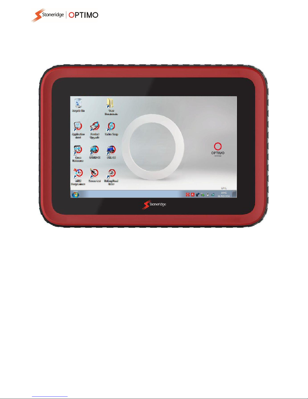
Stoneridge Optimo Manual
Stoneridge Electronics Ltd
Copyright
The information contained in this document is the property of Stoneridge
Electronics Ltd. and should not be reproduced, revealed or appropriated,
either in whole or in part, without the written authority of Stoneridge, Inc.
Page 2

2
Contents
1. Optim o Kit ................................................................................................................................................... 3
1.1. Optimo Light Kit .................................................................................................................................... 3
1.2. Optimo2 Kit ........................................................................................................................................... 4
2. Power – Optimo and Optimo Light ................................................................................................................ 4
2.1. Power – Optimo2 ................................................................................................................................... 5
3. Optimo Main Screen ..................................................................................................................................... 5
4. Optimo, Optimo Light and Optimo2 Features ................................................................................................. 6
5. Sleep mode .................................................................................................................................................. 6
6. Getting Started ............................................................................................................................................. 7
6.1. Task Bar Icons ....................................................................................................................................... 7
6.1.1. Workshop Settings ......................................................................................................................... 7
6.1.2. Connecting to WiFi ......................................................................................................................... 9
6.1.3. Bluetooth ...................................................................................................................................... 9
6.1.4. Wireless Connections ..................................................................................................................... 9
6.2. Connecting to Tachographs ................................................................................................................. 10
6.3. Calibrating and Programming .............................................................................................................. 10
7. Optimo – MKIII Programmer – Main screens............................................................................................... 11
7.1. Read and modify data......................................................................................................................... 12
7.2. Tachograph Information ..................................................................................................................... 13
7.3. Bench test .......................................................................................................................................... 14
7.4. Fixed distance 1 .................................................................................................................................. 15
7.5. Speed simulator .................................................................................................................................. 16
7.6. C3 RPM test ........................................................................................................................................ 16
7.7. DTCs .................................................................................................................................................. 17
7.8. k factor test......................................................................................................................................... 17
7.9. DIL calculate ....................................................................................................................................... 18
7.10. Fixed distance 2 .................................................................................................................................. 19
7.11. Rolling road......................................................................................................................................... 20
7.12. Clock test ........................................................................................................................................... 22
7.13. PIN ..................................................................................................................................................... 22
7.14. Serial data test ................................................................................................................................... 23
7.15. CANbus data test ................................................................................................................................ 23
7.16. 1000m test ......................................................................................................................................... 24
7.17. Sensor settings ................................................................................................................................... 25
7.18. Tachograph reset ................................................................................................................................ 27
8. Custom Bench Test ..................................................................................................................................... 28
9. SE5000CS – Configuration System ............................................................................................................... 32
10. 1381CS – Configuration System ................................................................................................................... 34
11. Application Sheets ...................................................................................................................................... 36
12. Cross Reference Tables ............................................................................................................................... 38
13. Tacho Swap ................................................................................................................................................ 39
14. Sensor Test ................................................................................................................................................ 41
15. Rolling Road Brake...................................................................................................................................... 45
16. Product Upgrade ........................................................................................................................................ 46
Annex A – Cable cross reference tables ............................................................................................................... 47
Annex B – Programmable Parameters ................................................................................................................ 49
Annex C – Optimo Error Codes ........................................................................................................................... 52
Page 3
3
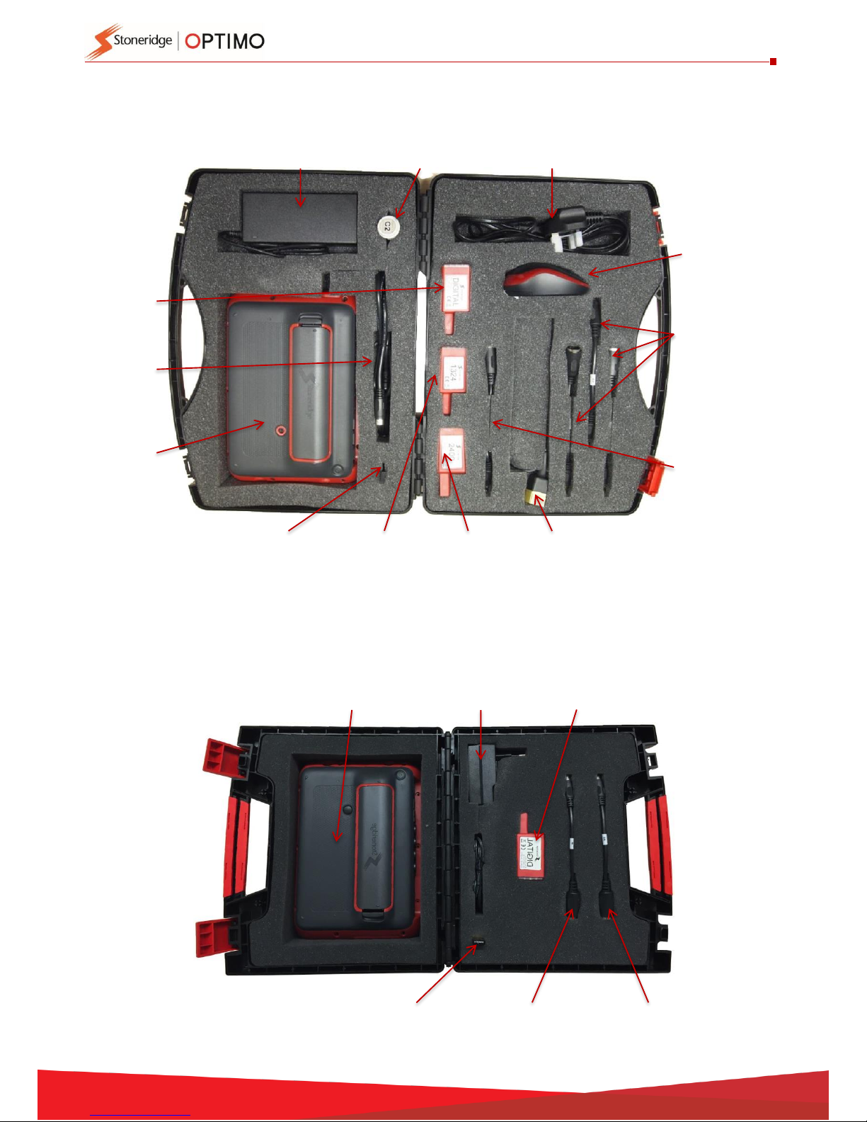
1. Optimo Kit
1.1. Optimo Light Kit
Optimo
Power
Supply
Bluetooth
Dongle
In Vehicle
Charger
Power
Cable
Mouse
C2 Cable
Tester
A4, A6 & A8
Tachograph
Adaptors
B Adaptor
For Stoneridge
Rolling Road &
Flexi Switch
C1 Cable
Tester
Digital
Dongle
1324
Dongle
2400
Dongle
Digital
Dongle
A8
Tachograph
Adaptor
Optimo
WiFi Dongle
Power
Supply
B Adaptor
For Stoneridge
Rolling Road &
Flexi Switch
Page 4
4
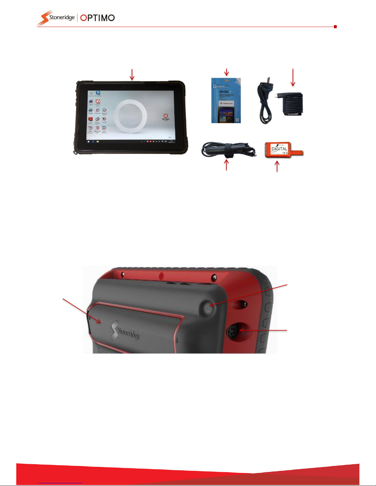
1.2. Optimo
2
Kit
2. Power – Optimo and Optimo Light
Lithium Ion 14.4V battery, life typically 4 hours.
Charging – 230V ac supply or vehicle power connector.
Charging time – typically one hour, overnight on first use.
Charging time for Optimo Light – typically up to 4 hours.
Power on/off
Power socket
for mains or
vehicle adaptor
Snap-fit
battery pack
Optimo
2
Digital Dongle
Power Supply
In Vehicle
Charger
Screen protector
Page 5
5
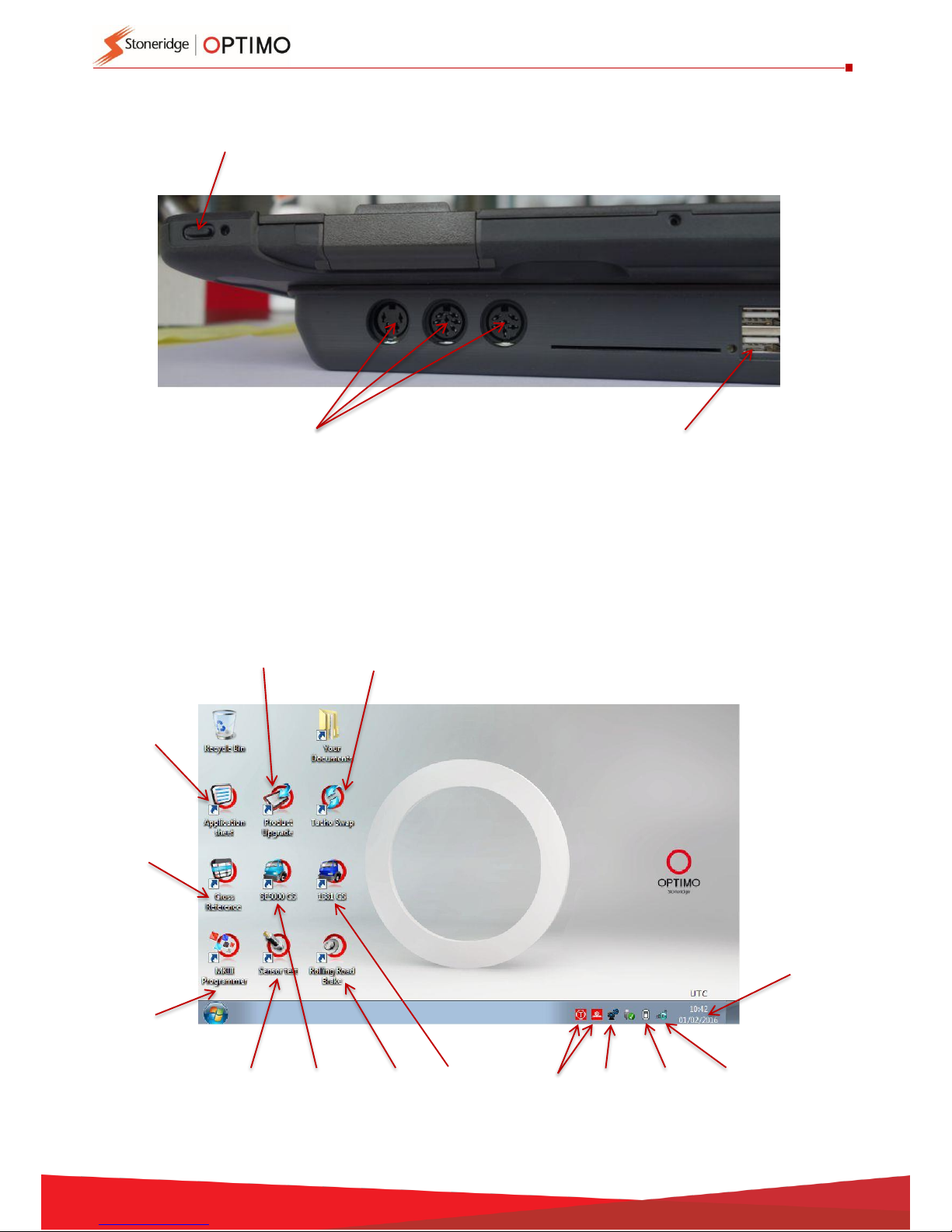
2.1. Power – Optimo
2
3. Optimo Main Screen
Optimo supports all digital and analogue tachographs. Extra cables may be required when using
Optimo Light. See table below.
Page 36
Page 38
Page 11
Page 22
Page 41
Page 32
Page 39
Page 46
Page 9
Page 9
Page 4
Page 34
Page 7
Page 45
Power on/off
USB ports
DIN sockets
Page 6
6
4. Optimo, Optimo Light and Optimo
2
Features
Component
Optimo
Optimo Light
Optimo2
External USB ports
4
2
2
Bluetooth
Yes
No
Yes
WiFi
Yes
Yes
Yes
External Mouse
Yes
No
No
Camera
Yes
No
Yes
Smart card reader
Yes
Yes
Yes
Dongles
Digital, 2400, 1324
Digital
Digital
I/O connectors
A,B,C,D,E,F,G
A,B,C
None, DIN
connectors only
Adaptor cables
A4, A6, A8 B, C1 and C2
connector
A8, B
None
Sensors, testing
Yes
No
No
Battery charge time
1 hour
4 hours
2.5 hours
Vehicle charger
Yes
No
Yes
Screen dimming
Yes
No
Yes
Screen rotation
Yes
No
Yes
Screen protector
Yes
No
Yes
5. Sleep mode
5 minutes inactivity
Screen blank – programs still running
Tap screen to wake up
30 minutes inactivity
Optimo shuts down
Press ON button at rear to re-start
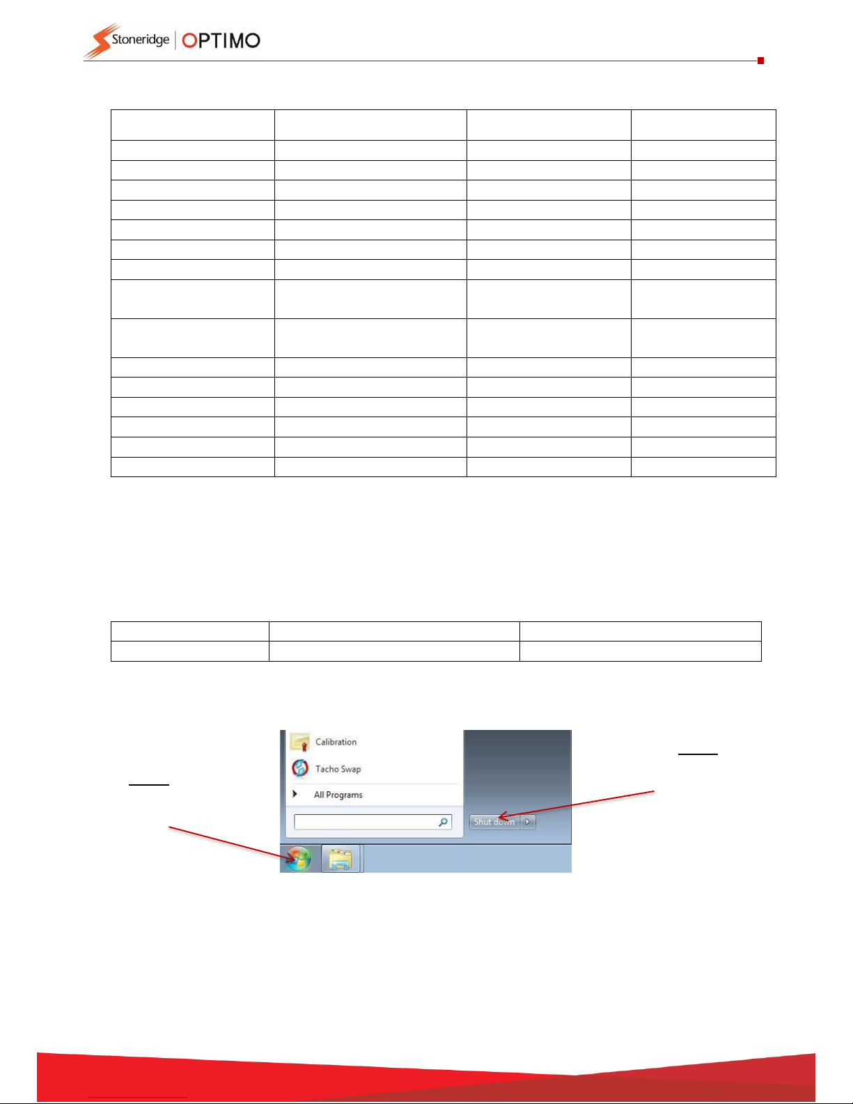
Power off.
Step 1
Tap
Windows icon
Step 2
Tap
Shut down
button
Page 7
7
6. Getting Started
How to set up your Optimo
6.1. Task Bar Icons
6.1.1. Workshop Settings
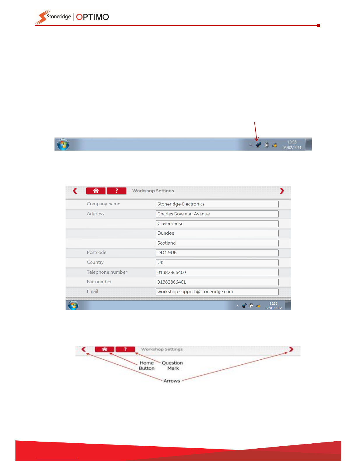
On first power up of Optimo a number of details must be entered into a series of
settings screens.
Settings screens can also be accessed at any time by tapping here.
After selecting Language and Country, enter your workshop details. Complete all fields.
Other screens are accessed by tapping Arrows at the top of the page if highlighted.
The ‘Home’ button closes any application and returns to the Windows desktop or
returns to that application’s main screen.
Page 8
8
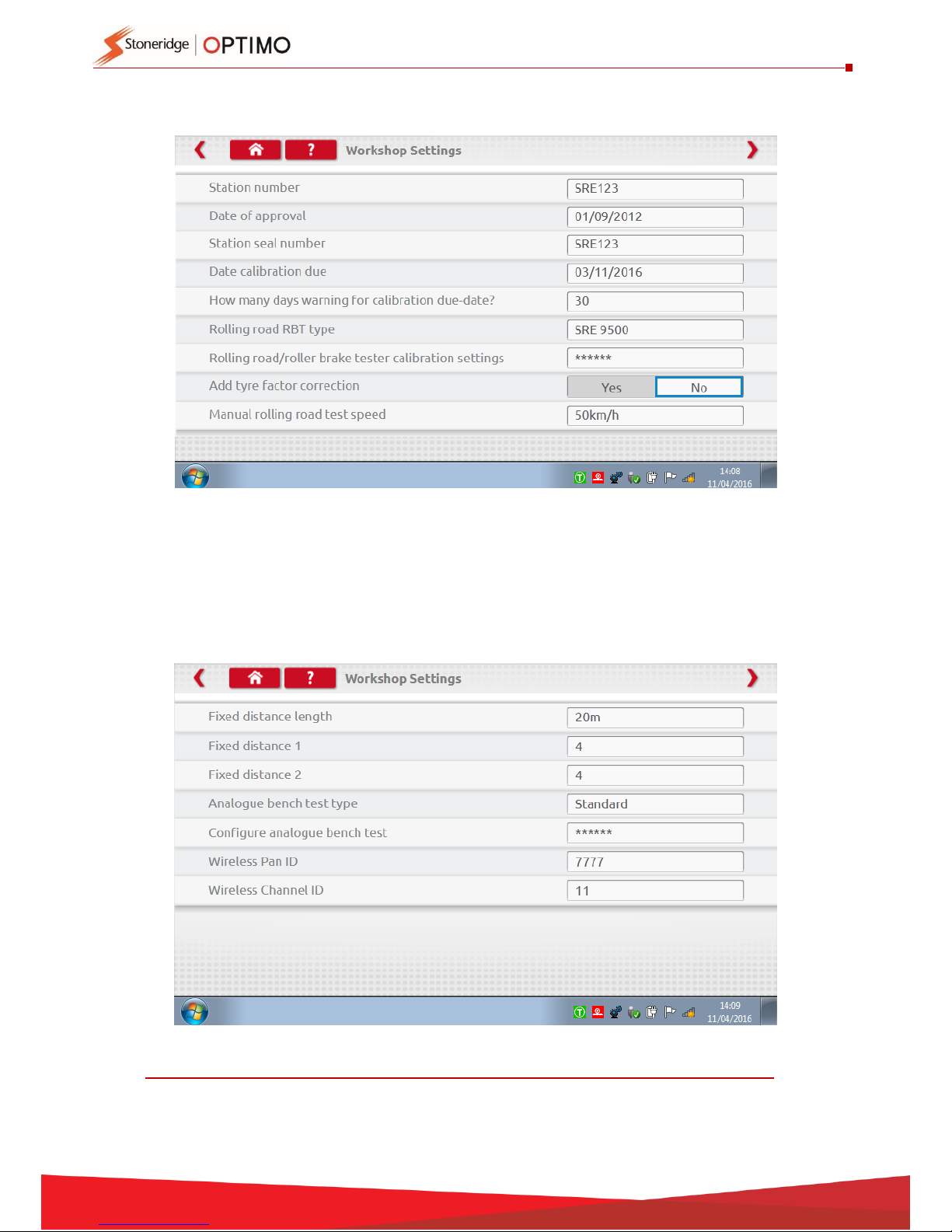
This screen displays various details about your workshop, and enables selection
and settings for Rolling Roads. Complete all fields.
x
The next screen sets Fixed distance length and number of runs, plus options for
“Standard” or “Custom” bench tests. For Custom Bench test see Chapter 8, page 28
DETAILS ON ALL THESE SCREENS MUST BE COMPLETED BEFORE FIRST USE OF OPTIMO.
Page 9
9
6.1.2. Connecting to WiFi
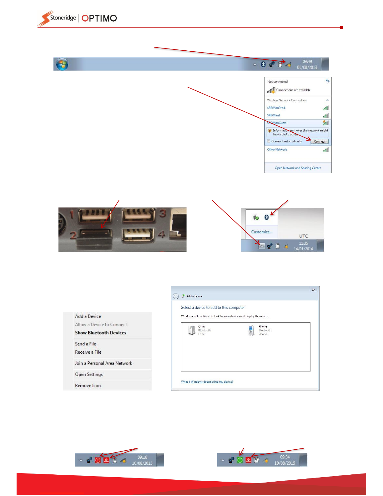
Tap the Internet icon.
6.1.3. Bluetooth
Insert Bluetooth dongle to USB port, press white arrow and a Bluetooth icon appears.
On pop up screen tap “Add a Device”, a new screen appears showing other Bluetooth
devices in the area. Tap on selected device and follow prompts to pair it with Optimo.
6.1.4. Wireless Connections
There are two wireless indicators in the taskbar, one for connection to the tachograph
and one for connection to a Rolling Road. Both are red when disconnected and turn
green when connected.
Select the network and tap “Connect” button.
Tachograph & Rolling Road disconnected
Tachograph connected, Rolling Road disconnected
Page 10
10
6.2. Connecting to Tachographs
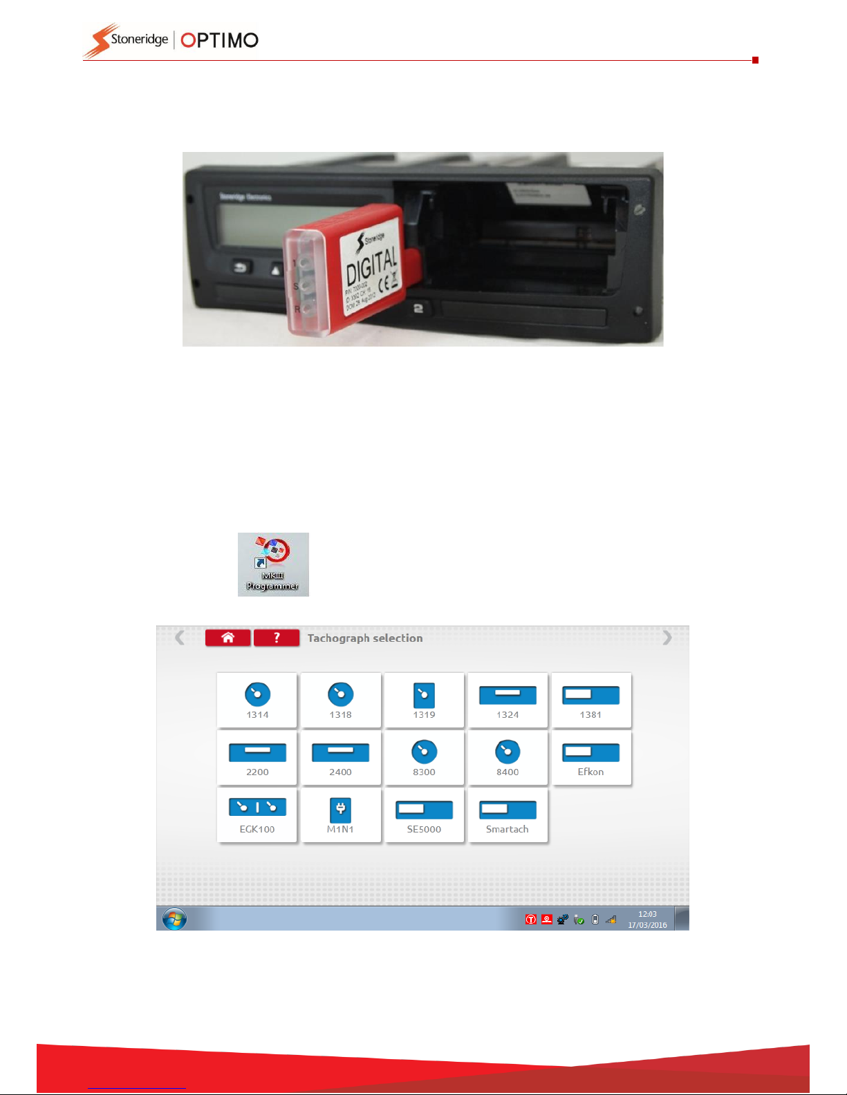
3 dongles are supplied for Digital, 2400 and 1324 tachographs. These are inserted into the
programming socket as shown, wait 5 seconds after insertion before initiating programmes.
All tachographs can also be connected using existing MKII cables via supplied adaptor cables.
This is the only way to connect to round tachographs.
Optimo Light and Optimo
2
are supplied with the Digital dongle only.
6.3. Calibrating and Programming
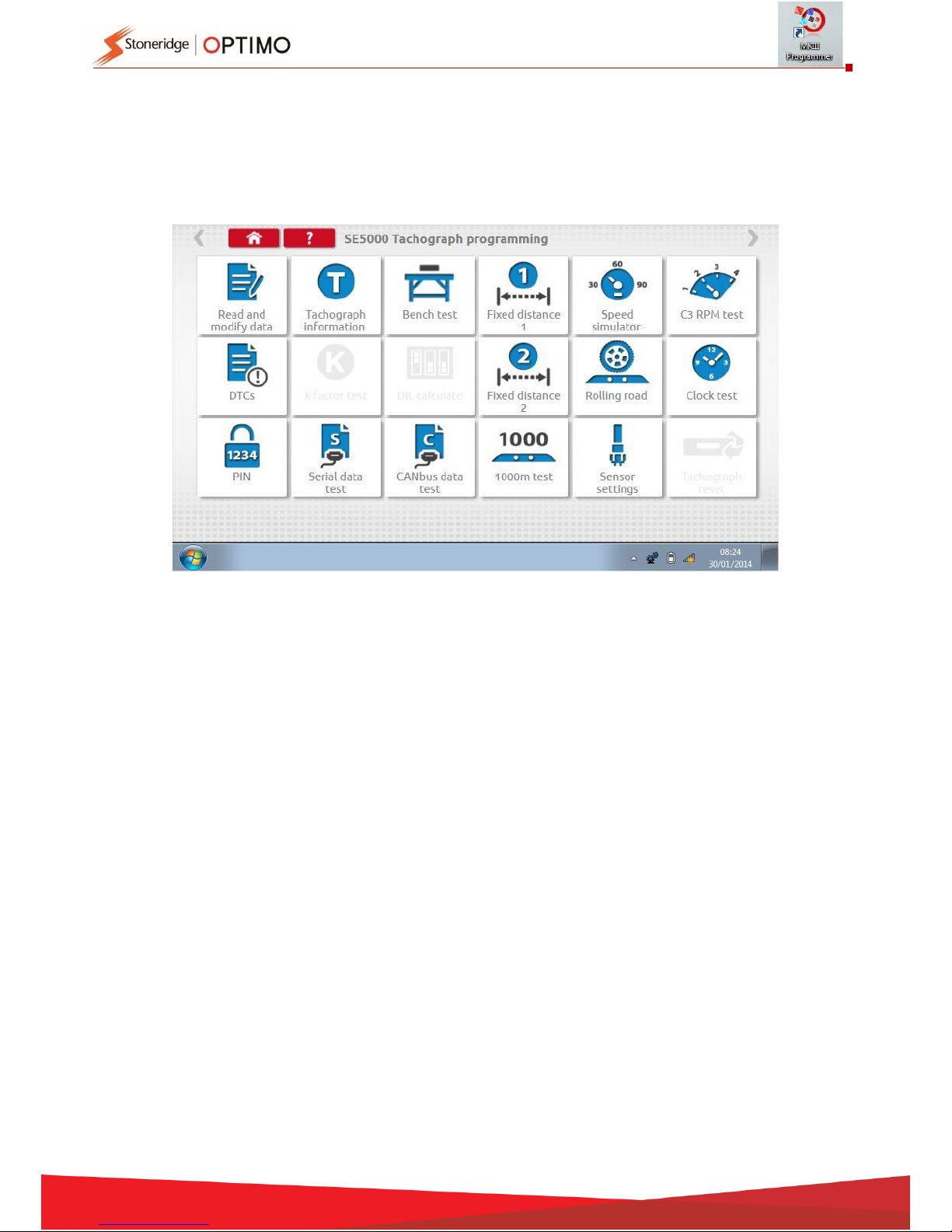
On tapping Optimo identifies the connected tachograph. If the tachograph
cannot be determined the screen below is displayed. Select
tachograph type.
Page 11
11
7. Optimo – MKIII Programmer – Main screens
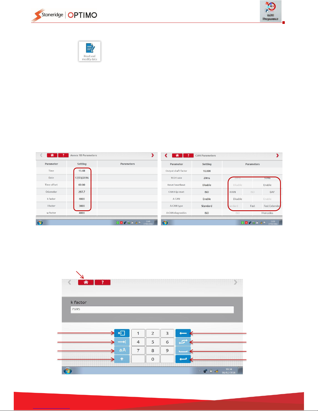
When a tachograph is detected or selected, the screen below is displayed.
On these screens highlighted icons can be selected, those dimmed out cannot.
The following sub-chapters briefly explain the function for each icon selection.
Read and modify data
Chapter 7.1
Tachograph information
Chapter 7.2
Bench test
Chapter 7.3
Fixed distance 1
Chapter 7.4
Speed simulator
Chapter 7.5
C3 RPM test
Chapter 7.6
DTCs
Chapter 7.7
K factor test
Chapter 7.8
DIL calculate
Chapter 7.9
Fixed distance 2
Chapter 7.10
Rolling road
Chapter 7.11
Clock test
Chapter 7.12
PIN
Chapter 7.13
Serial data test
Chapter 7.14
CANbus data test
Chapter 7.15
1000m test
Chapter 7.16
Sensor settings
Chapter 7.17
Tachograph reset
Chapter 7.18
Page 12
12
7.1. Read and modify data
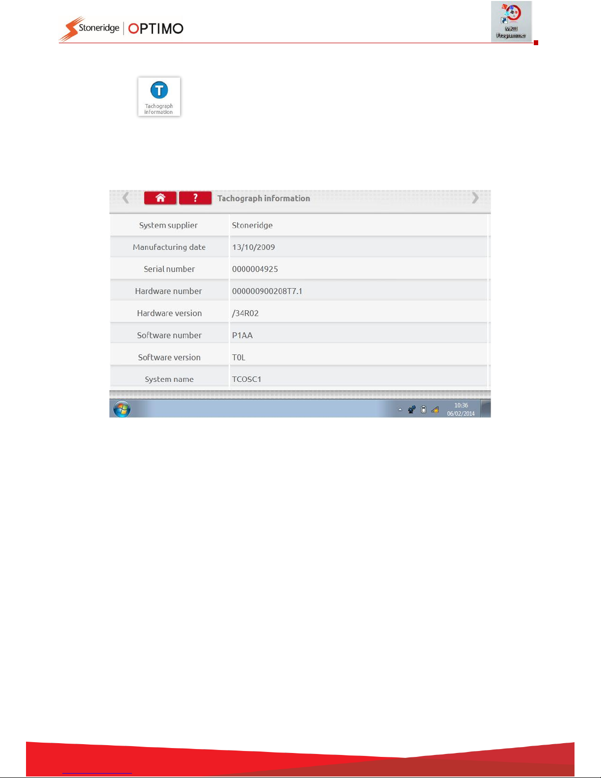
Select on the tachograph programming screen.
Parameters are changed by tapping values in the “Setting” column, or for some parameters by
selecting appropriate buttons. A new screen is then displayed along with the necessary
keyboard.
Note 1: In all cases, once settings have been altered, tapping the enter key immediately sends
that information to the tachograph. More screens are accessed by using highlighted arrows at
the top of the page.
Note 2: For some tachographs, such as the Actia, once a setting has altered it will change colour
to show the setting has been changed but it will not send to the tachograph until you tap the
Home button at the top of the page, whereupon it sends all data.
To change a value use Backspace to remove characters, enter new value, then tap the Enter key
to update the tachograph.
Tap the Home button to return to main programming screen.
Enter
Toggle
Space
Backspace
Escape
Tab
Caps
Shift
Page 13
13
7.2. Tachograph Information
Tap
Available on all Digital tachographs. Require dongles, or cables plus adaptors for 1324 and 2400
tachographs.
Page 14
14
7.3. Bench test
Tap
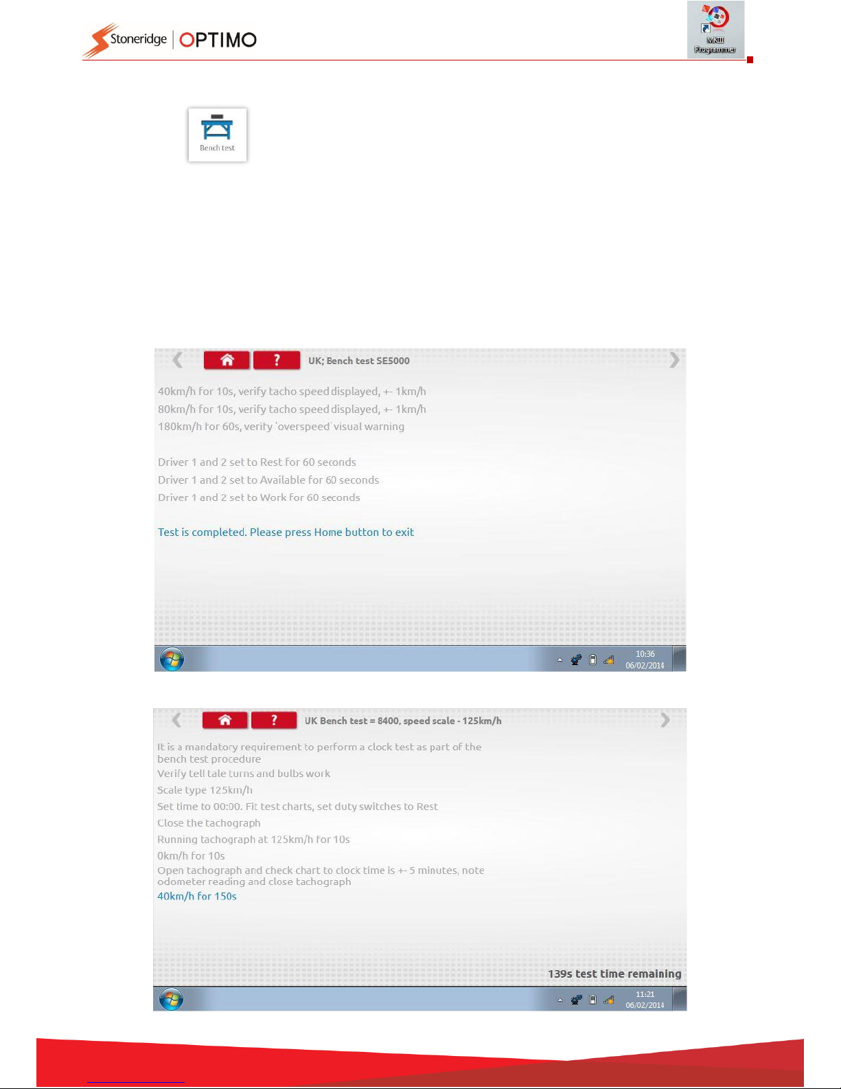
For radio sized tachographs these tests are carried out semi automatically, with a countdown
timer displaying time remaining for each phase of the test.
For round tachographs a speed scale first must be selected first.
Note: for calibration a Clock Test must be carried out either before or after an analogue bench
test.
For all bench tests follow on screen prompts, and select buttons, duties etc. as required.
Digital Bench test
Analogue Bench test
Page 15
15
7.4. Fixed distance 1
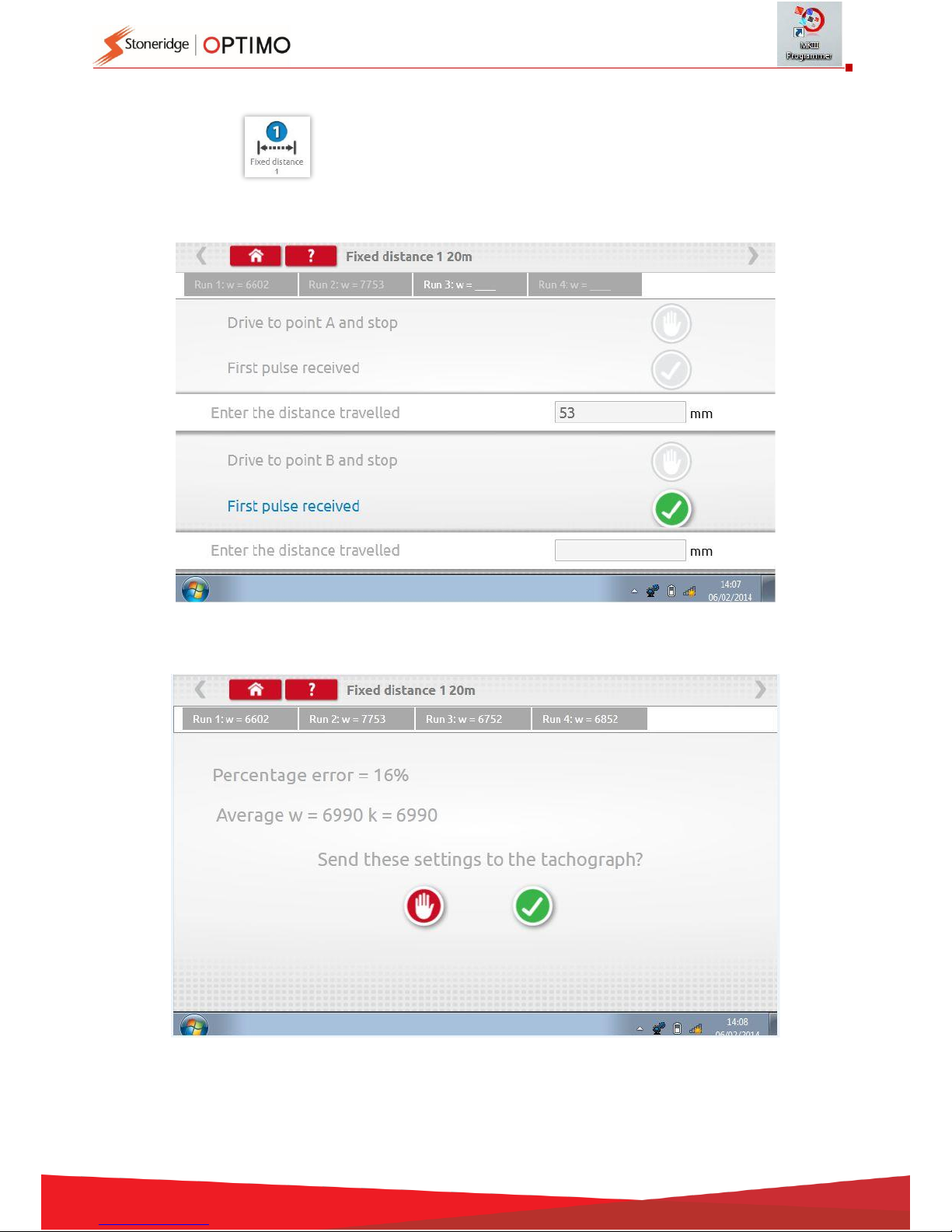
Tapping enables the “w” factor to be determined using a physical method with a
fixed pointer over a fixed distance.
The “w” value for each run is displayed. Carry out the appropriate runs as prompted.
Test complete.
For round tachographs, DIL switch settings will be shown which must be manually set.
Page 16
16
7.5. Speed simulator
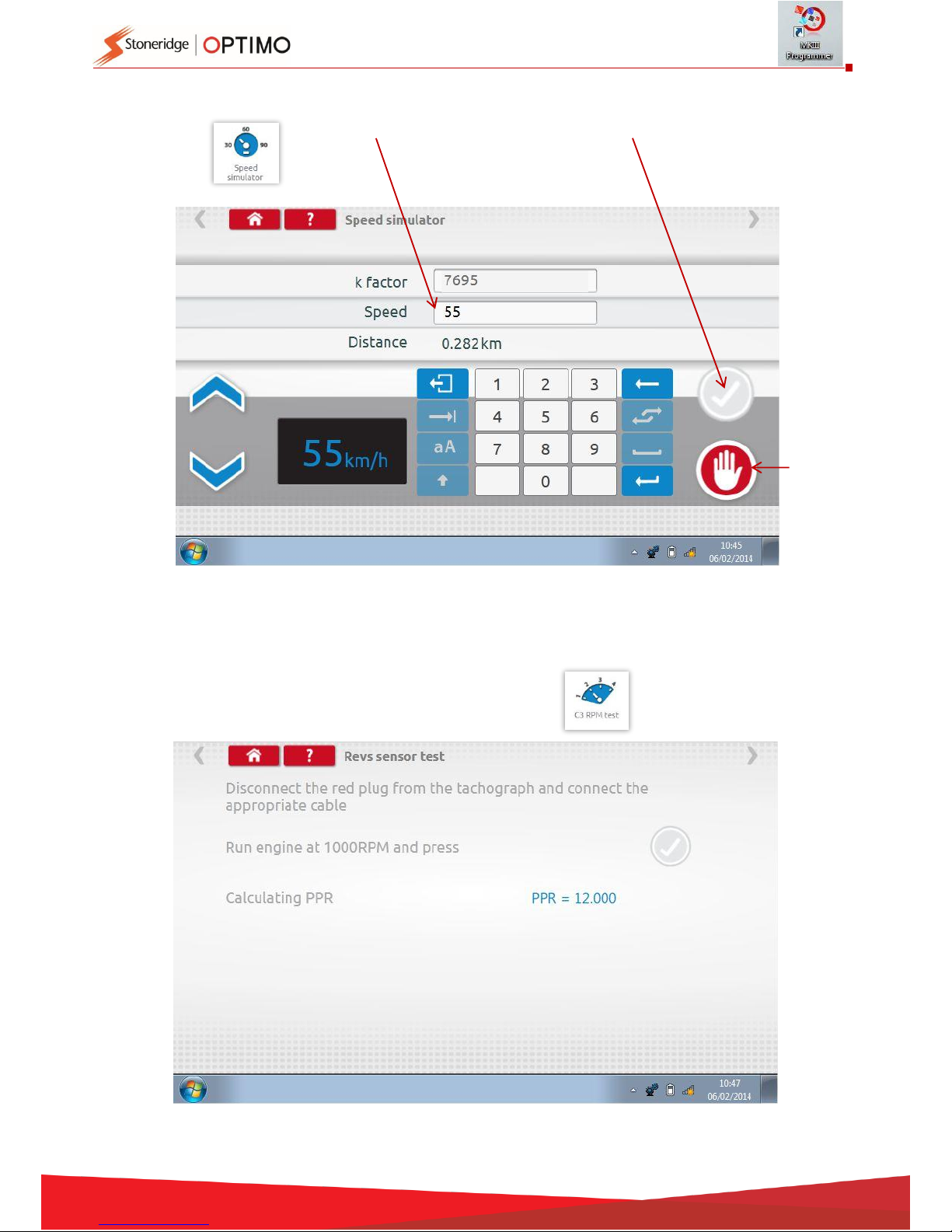
Tap then tap “Speed” box and enter speed, then tap the tick button.
7.6. C3 RPM test
Connect cable E via adaptor A6 for Optimo only. Tap
Stop
Test
Increment
Speed
Decrement
Speed
Page 17
17
7.7. DTCs
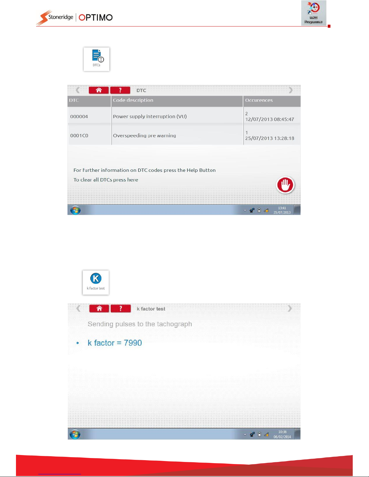
Tap
Current faults must be rectified before the vehicle leaves the workshop.
7.8. k factor test
Tap and using cable G via adaptor A6, Optimo only, on a 8400, 1318 or 1314 it will
provide a reading of the k factor.
Page 18
18
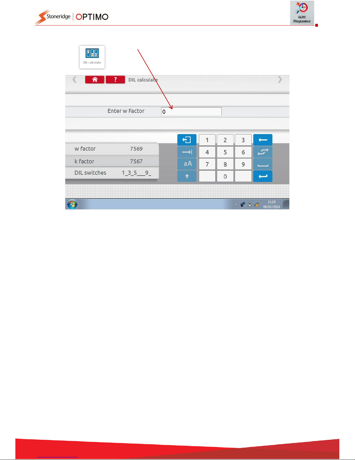
7.9. DIL calculate
Tap enter w factor. DIL switch settings, w factor and k exact are displayed on left.
This function does not require connection to a tachograph.
Page 19
19
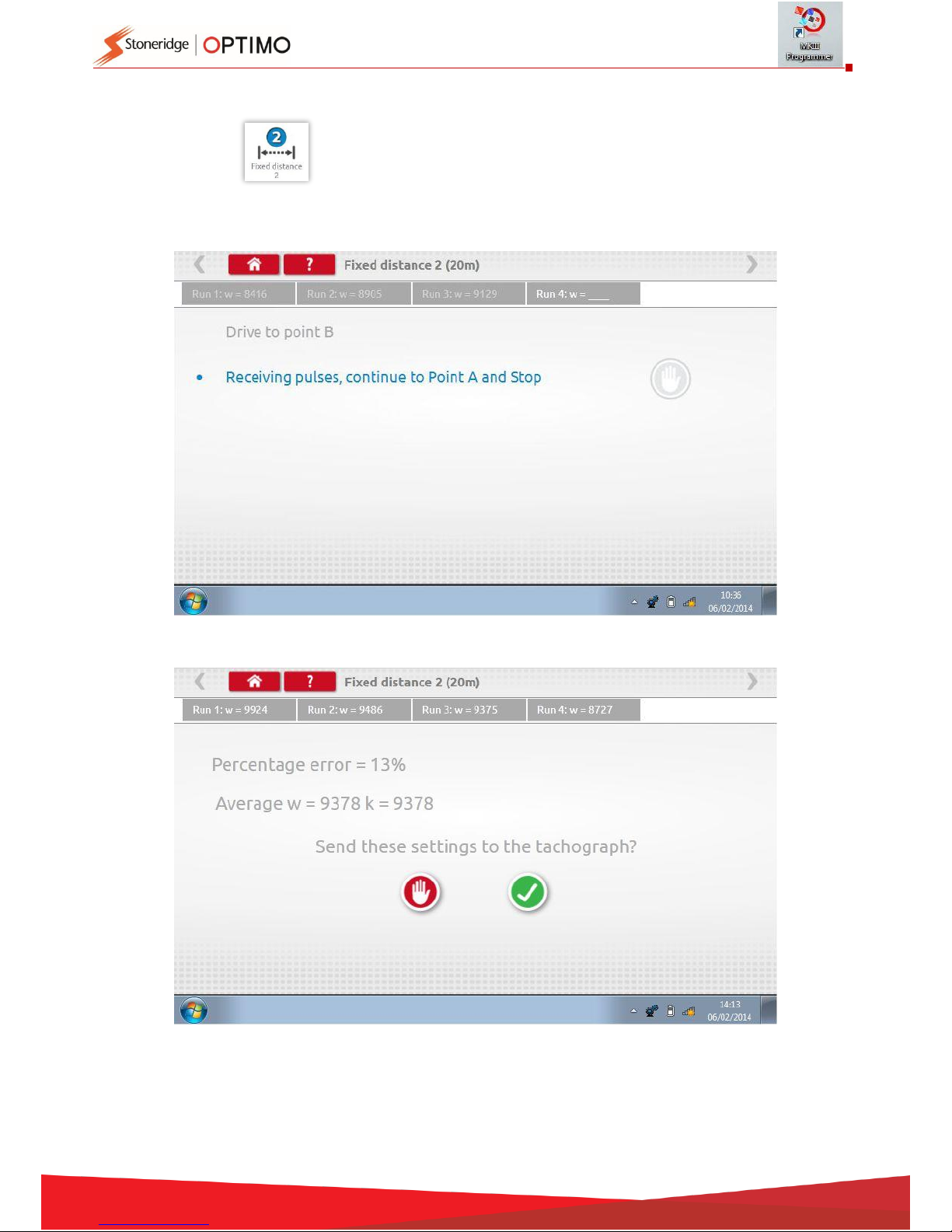
7.10. Fixed distance 2
Tapping enables the “w” factor to be determined using a physical method with an
external device such as a flexi switch or light barriers over a fixed
distance. Connect the flexi switch or light barrier device via adaptor B.
The “w” value for each run is displayed. Carry out appropriate runs as prompted.
Test complete.
For round tachographs DIL switch settings will be shown which must be manually set.
Page 20
20
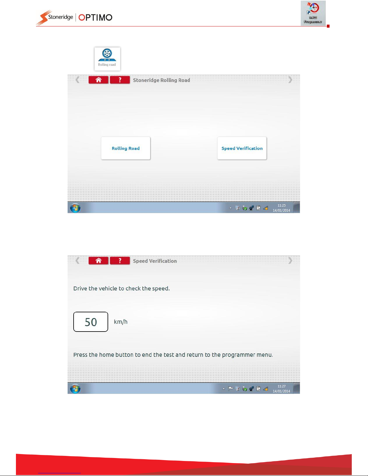
7.11. Rolling road
Tapping enables selection of Rolling Road test or Speed Verification.
With vehicle in motion, tap “Speed Verification”, check speed of Rolling Road and compare with
tachograph speed i.e. speed for speed check.
Page 21
21
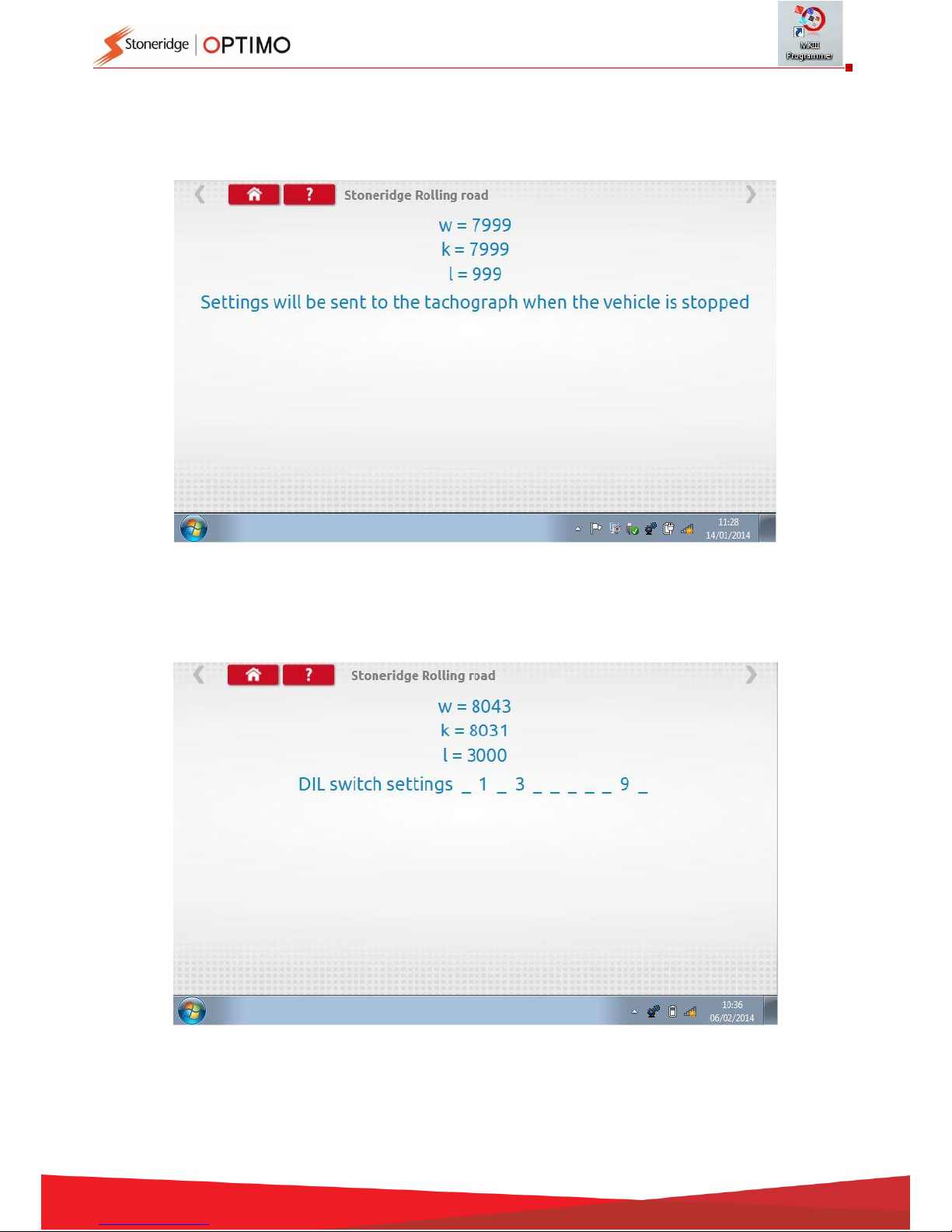
For a Stoneridge rolling road, when you tap “Rolling Road” Optimo determines the w and l
factors. When test complete results can be sent directly to radio sized tachographs, followed by
a confirmation screen.
For round tachographs w, k and l factors are displayed, plus the DIL switch settings which must
be manually changed.
Page 22
22
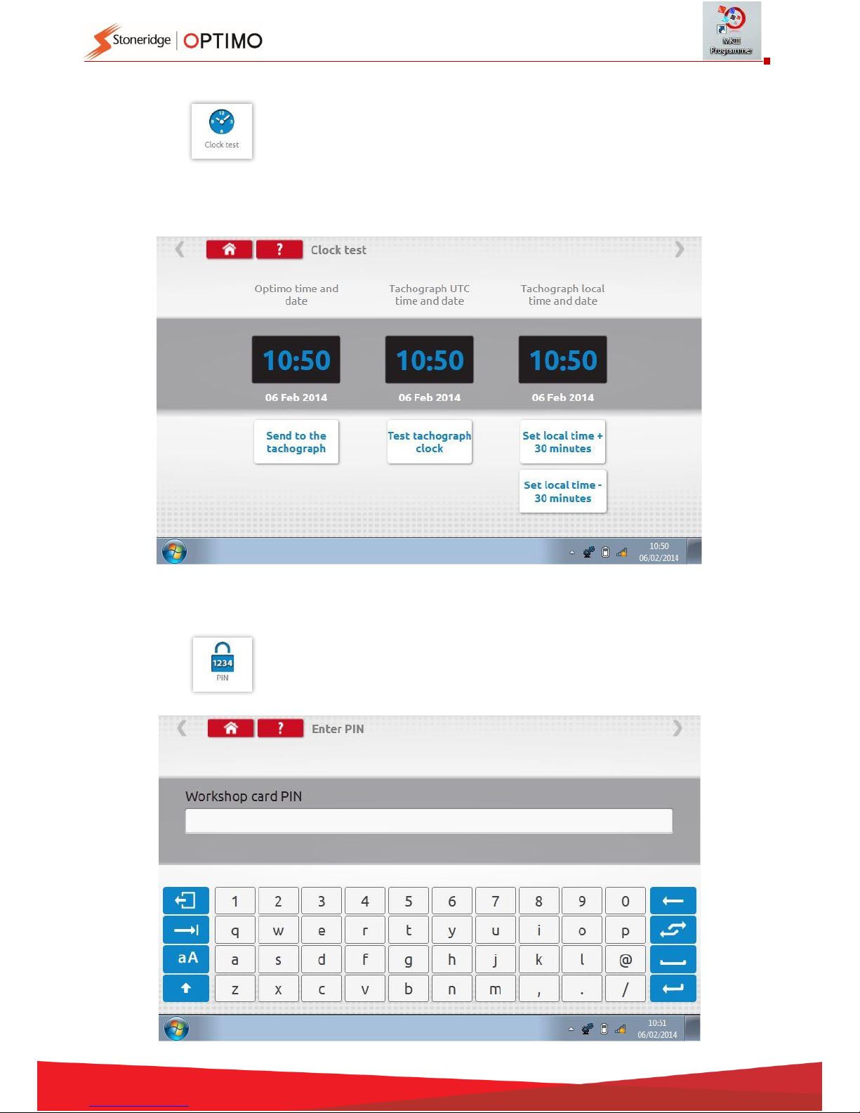
7.12. Clock test
Tap to check accuracy of clock and adjust UTC and local time if necessary. For
round tachographs a clock tester module is required and only tests the
accuracy of the clock.
Optimo is factory set to UTC time.
On Digital tachographs all time adjustments should be done from this menu.
7.13. PIN
Tap enter workshop card PIN. Available on SE5000 and DTCO 1381 only.
Page 23
23
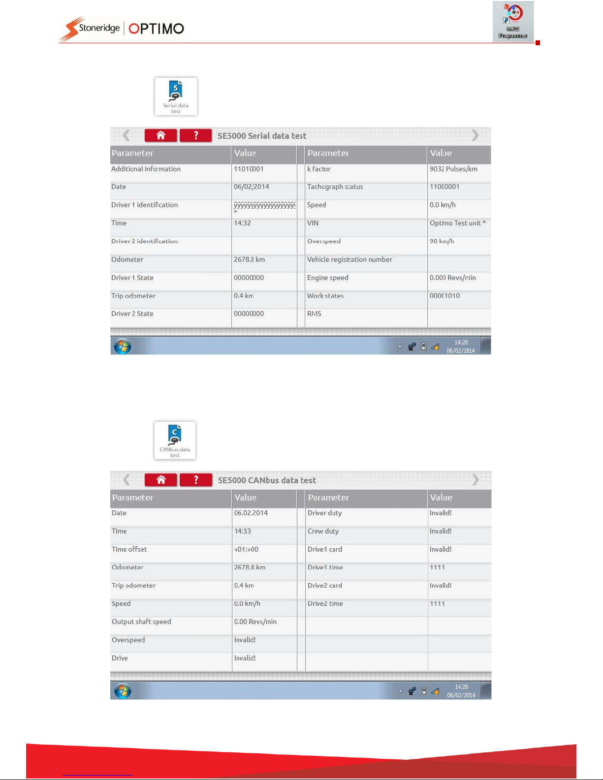
7.14. Serial data test
Tapping displays serial data from the tachograph via cables F & H plus adaptor
A4 for a SE5000, or cables X & H and A4 for a 2400, Optimo only.
7.15. CANbus data test
Tapping displays CANbus data via cable V and adaptor A.
Page 24
24
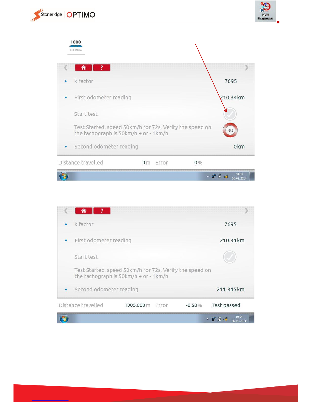
7.16. 1000m test
Tap the k factor is displayed, tap the green tick button, the test starts and a
countdown timer appears in a red circle.
Test complete.
Page 25
25
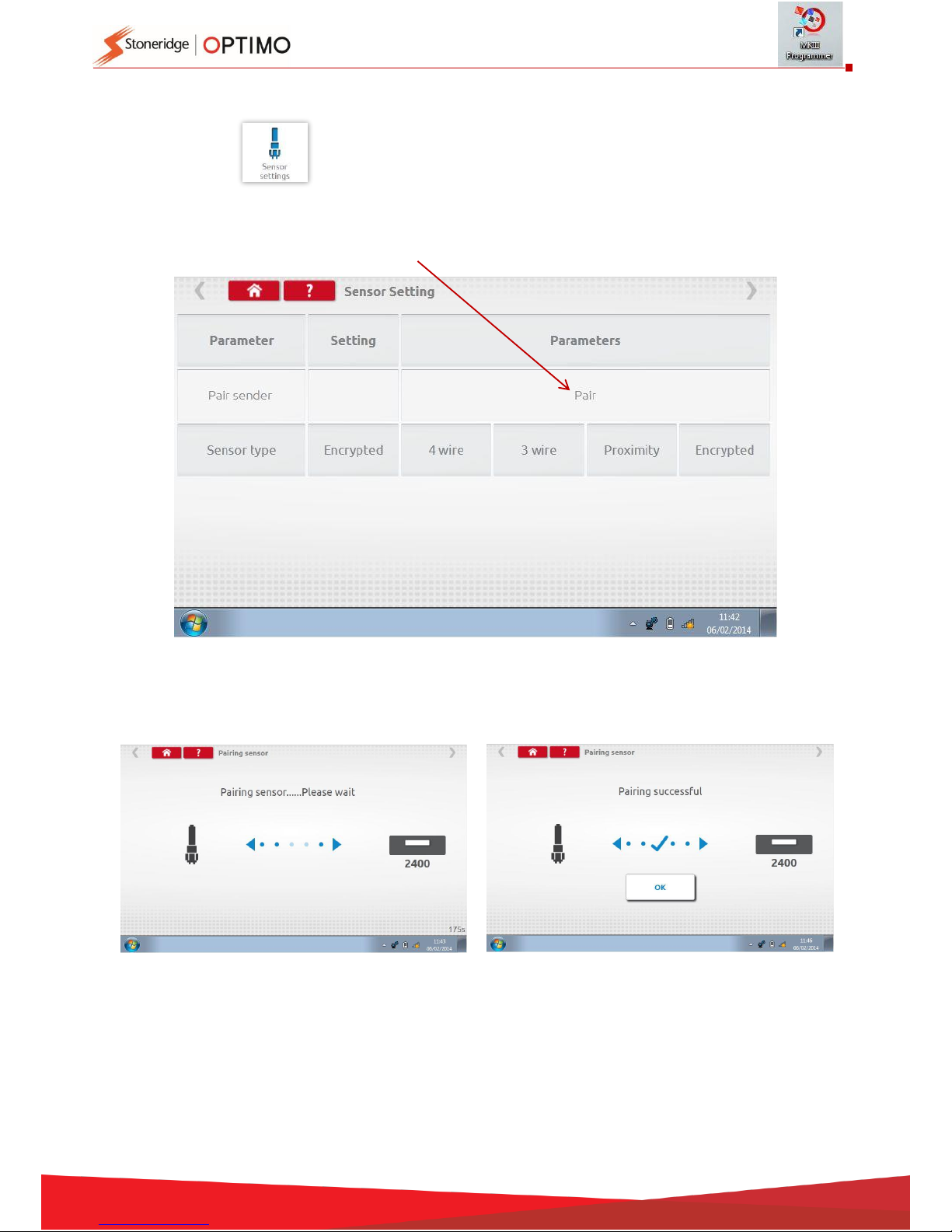
7.17. Sensor settings
Tapping enables selection of a sensor type on some tachographs.
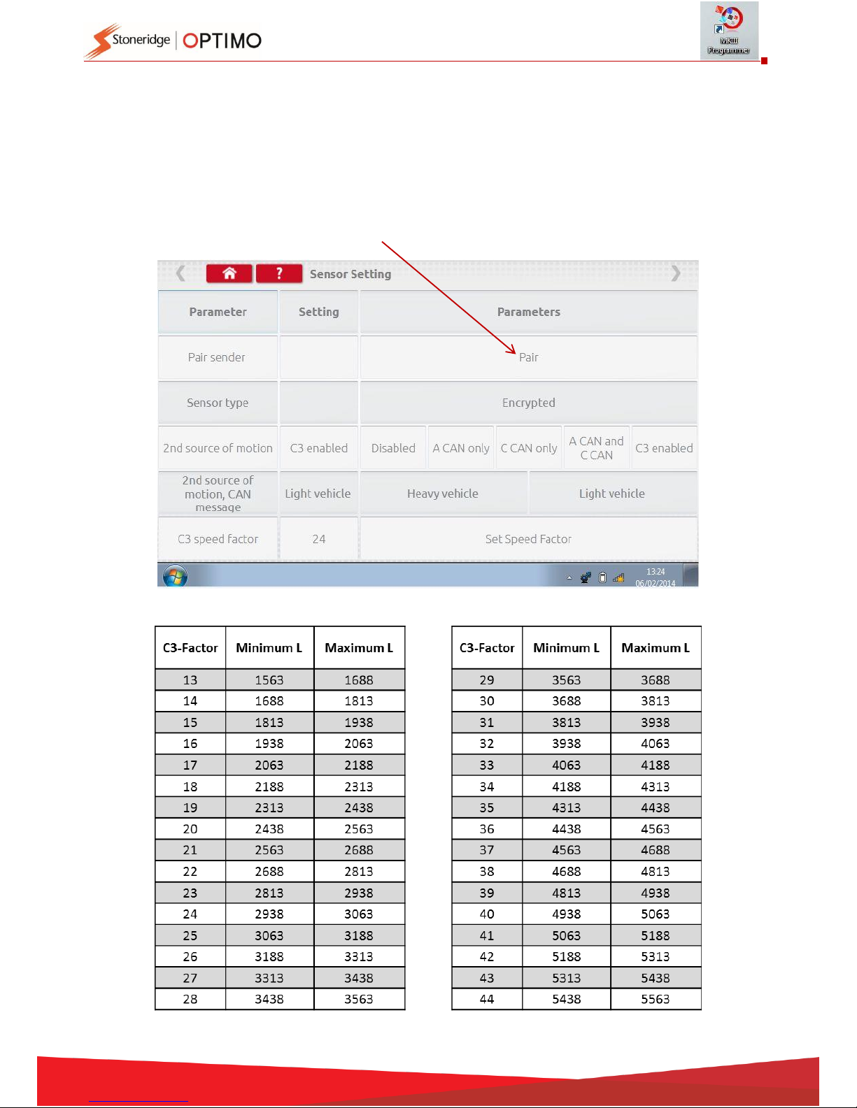
The following screen is for a VR2400.
To pair an Encrypted sensor tap “Pair”.
Test complete.
Page 26
26
For 3
rd
generation digital tachographs activated after 1st October 2012, the following screen is
displayed. 2nd source of motion is enabled by selecting the appropriate CANbus or the C3 option.
For CANbus “Heavy” or “Light” vehicle also has to be selected as data is transferred at different
bit rates.
If C3 is enabled, a speed factor, derived from the l factor value has to be entered to match the
two speed signals as close as possible, see table 1.
To force pair a digital sender, tap “Pair”.
Table 1
Page 27
27
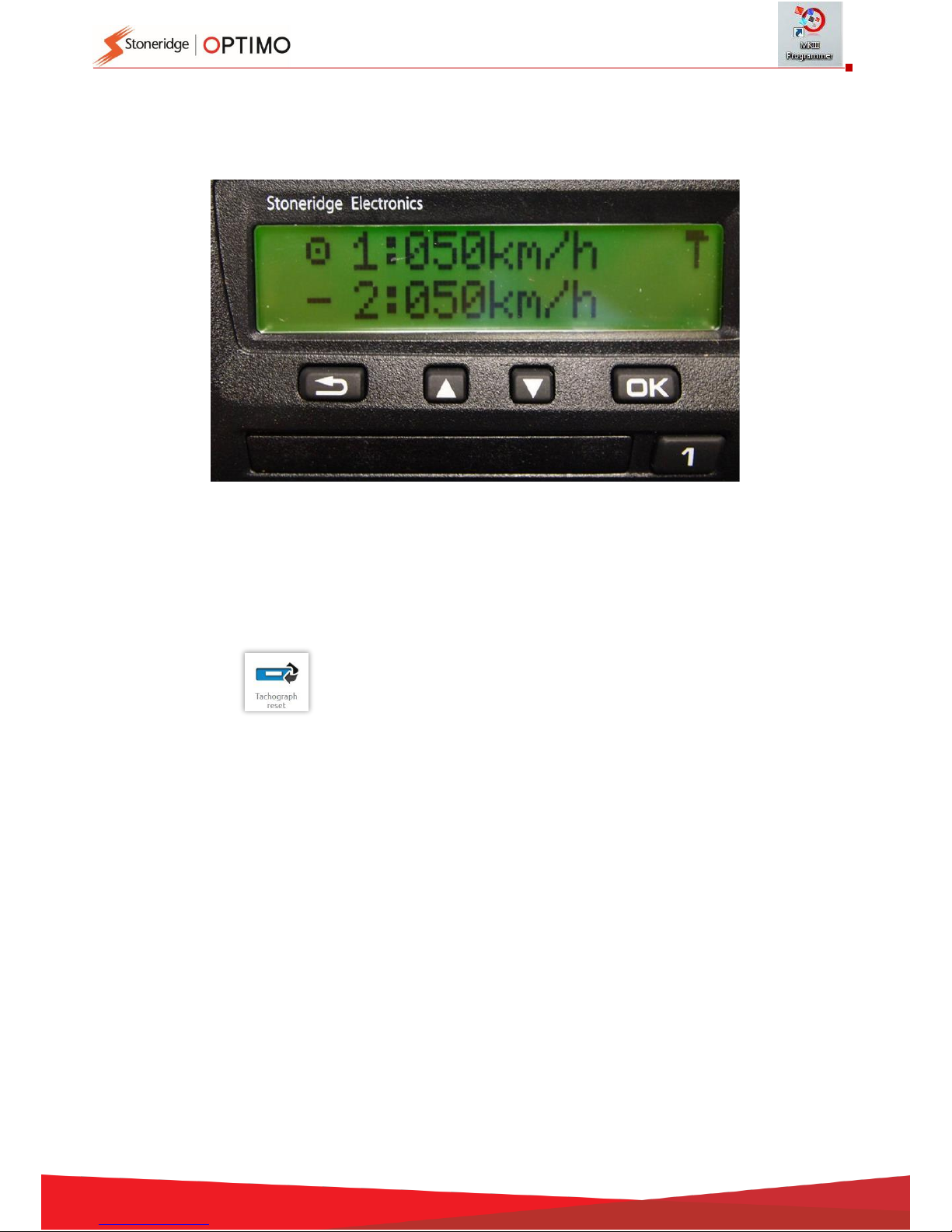
It is essential that the speed on the second source is closely matched to the speed from the
gearbox sensor. To verify this, and correct where necessary, press the up arrow on the
tachograph once to view the dual speed source screen as shown below.
Run the vehicle at 50km/h and adjust the C3 speed factor until speed 2 is as close to speed 1 as
possible. The difference between speed 1 and speed 2 must not exceed 10km/h.
7.18. Tachograph reset
Tapping sends a reset pulse by simulating an Off/On condition which resets
default in the tachograph. No screen displayed on Optimo, however
there is an interruption on the tachograph display.
Page 28
28
8. Custom Bench Test
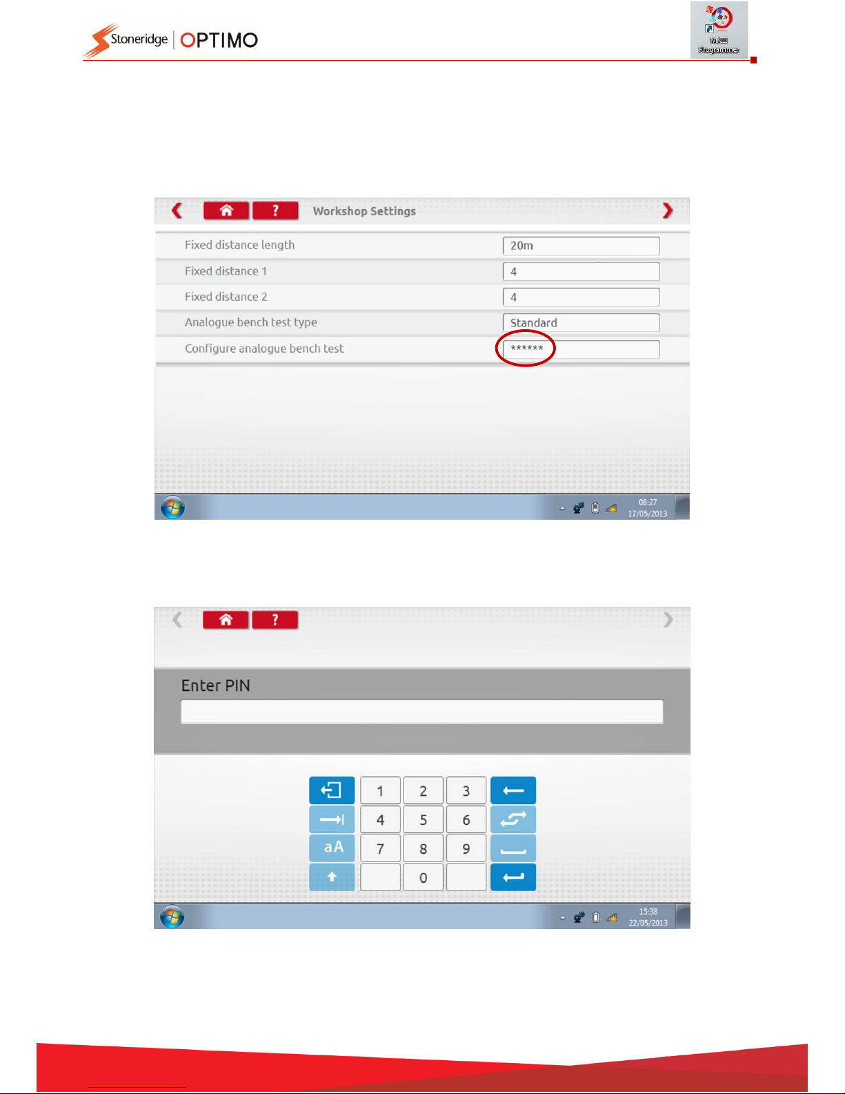
For analogue tachographs, a Custom bench test allows a technician to set unique duty and speed
parameters in countries which allow this. To set a Custom bench test go to page 3 of “Workshop
Settings” then tap on stars in the box adjacent to “Configure analogue bench test” in 3rd
“Workshop Settings” screen.
Enter a PIN, which is obtained from your SRE representative or usual supplier.
Page 29
29
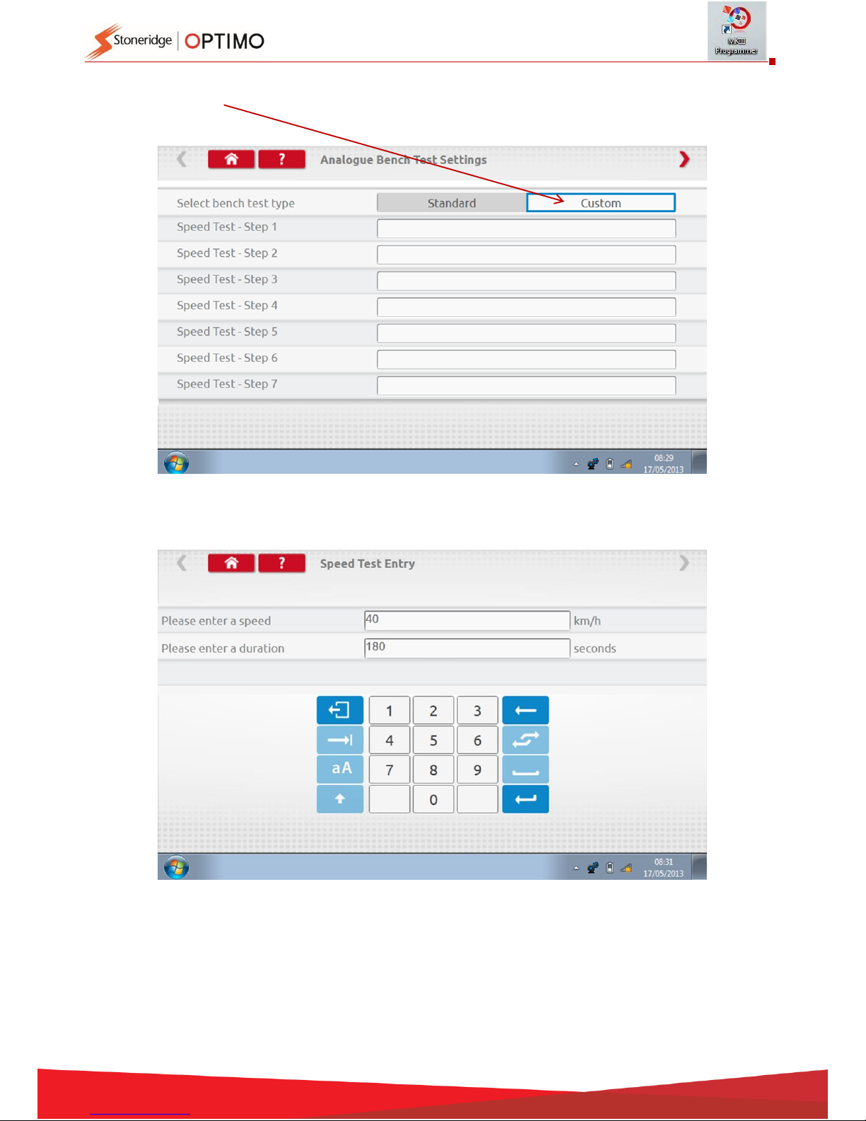
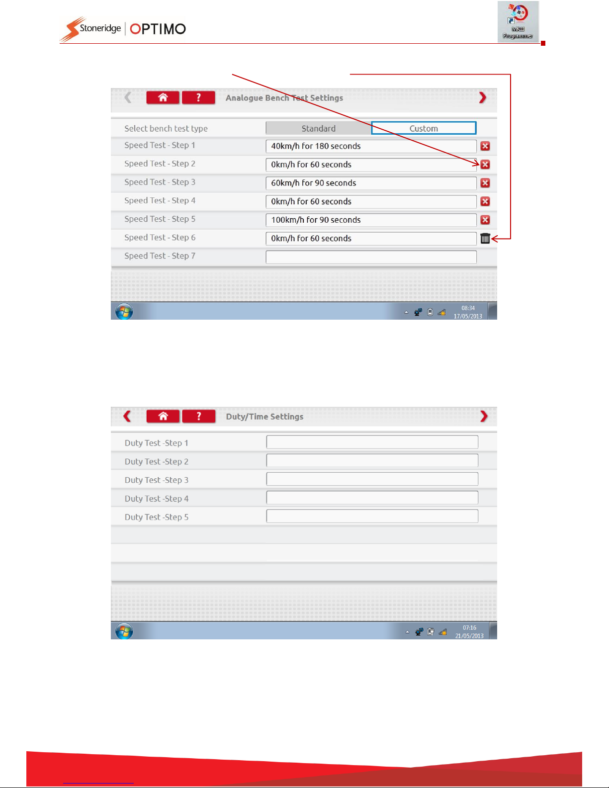
Tap “Custom” to enter up to 15 Speed Test steps.
Tap an empty box adjacent to each Speed Test step then enter the speed and duration of step.
Page 30
30
To delete a step, tap the cross in the red box, then tap bin icon and step is deleted.
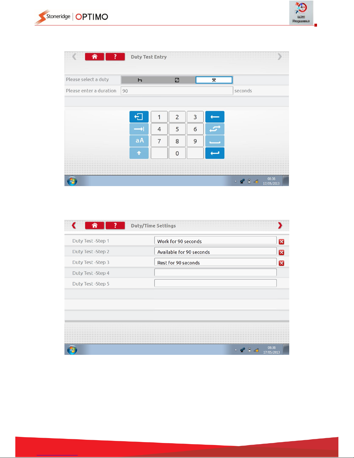
Once all Speeds entered, tap red arrow top right to enter up to 5 duty steps. Tap an empty box
adjacent to a “Duty Test” step.
Page 31
31
Tap the Duty required, then key in duration for test.
Once final Duty test is entered, tap red arrow top right, or Home Button, to exit setup procedure.
Now when running an Analogue Bench test the tachograph type will be prefixed with “Custom
Bench Test”. On radio sized analogue tachographs “Auto Duty” is selected On or Off by tapping
the appropriate button, then follow on-screen prompts as normal.
Page 32
32
9. SE5000CS – Configuration System
Tap and a message “Determining the Tacho Type” is displayed whilst Optimo confirms
an SE5000 tachograph is connected. This enables configuration of KRM
tachographs to parameters of different vehicle types.
A valid workshop card must be inserted and PIN authenticated to reconfigure all activated
tachographs.
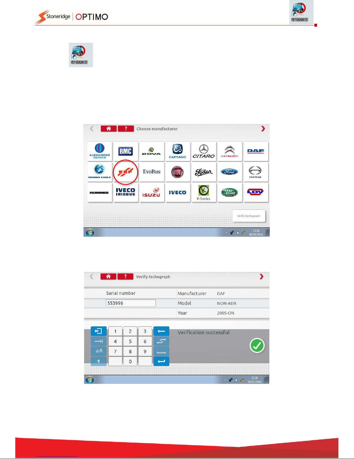
Choose manufacturer by tapping appropriate icon, or tap “Verify Tachograph” to input a serial
number.
If verification successful, make and model of a configured tachograph is displayed.
Page 33
33
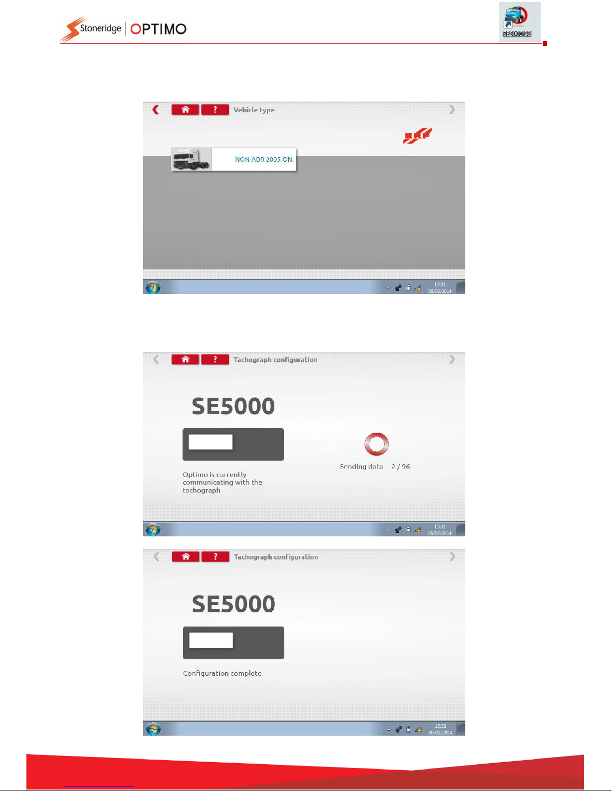
To configure to another vehicle type, tap appropriate Manufacturer’s icon and a list of associated
vehicle types is displayed.
Tap icon for correct vehicle type, and a screen shows Optimo communicating with the tachograph.
After a short time the result is displayed.
Page 34
34
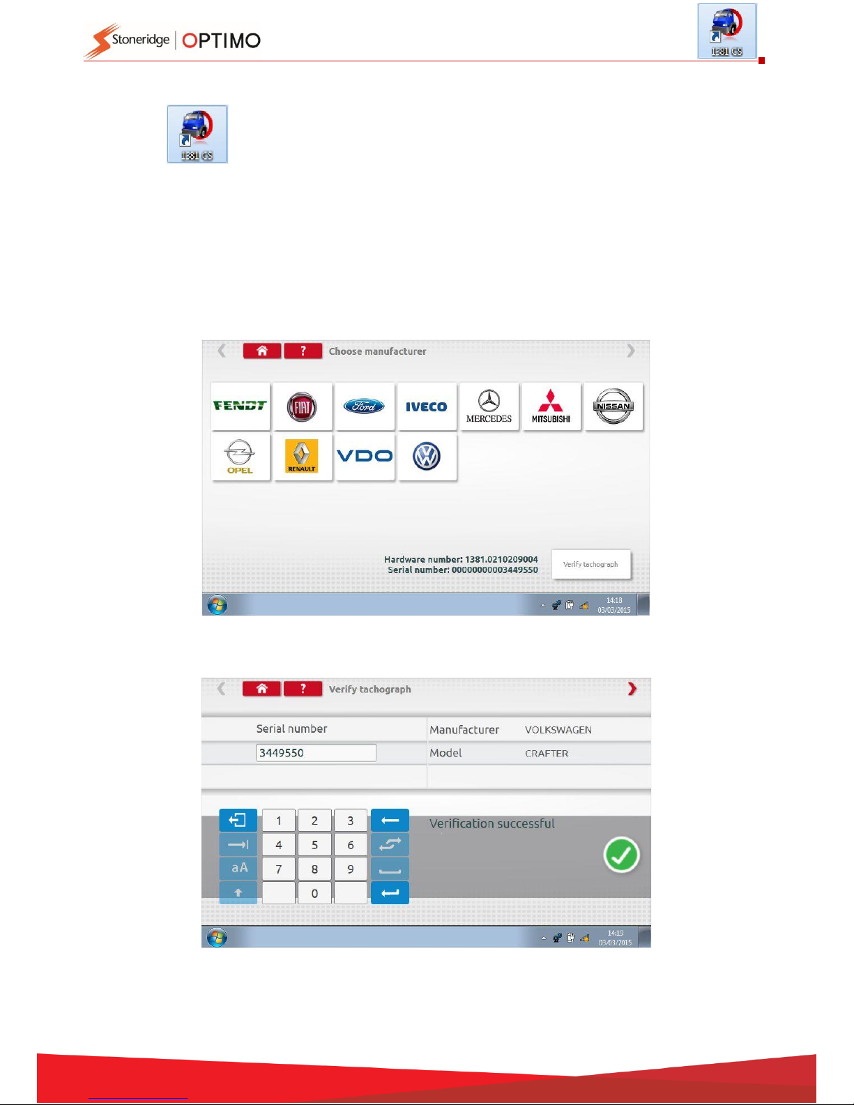
10. 1381CS – Configuration System
Tap and a message “Please check the 1381 Tachograph (Universal model rev 2.1) is
connected using a wired connection before beginning the Configuration.” is
displayed. Do not use this feature when in wireless operation.
Then a new message “Determining the Tacho Type” is displayed whilst Optimo
confirms a 1381 tachograph is connected. This enables configuration of 1381 tachographs to
parameters of different vehicle types.
A valid workshop card must be inserted and PIN authenticated to reconfigure all activated
tachographs.
Choose manufacturer by tapping appropriate icon, or tap “Verify Tachograph” to input a serial
number.
If verification successful, make and model of a configured tachograph is displayed.
Page 35
35
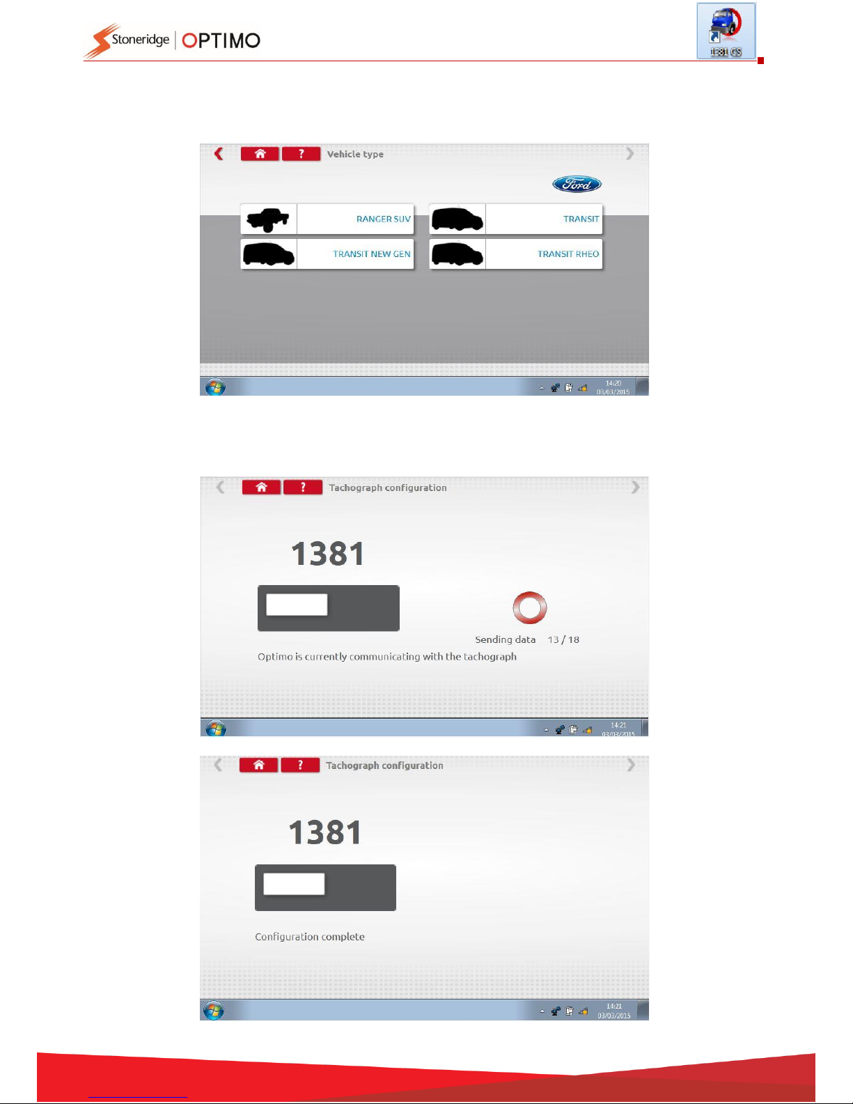
To configure to another vehicle type, tap appropriate Manufacturer’s icon and a list of associated
vehicle types is displayed. Select the 1381 Universal Model and then select your target vehicle type.
Tap icon for correct vehicle type, and a screen shows Optimo communicating with the tachograph.
After a short time the result is displayed.
Page 36
36
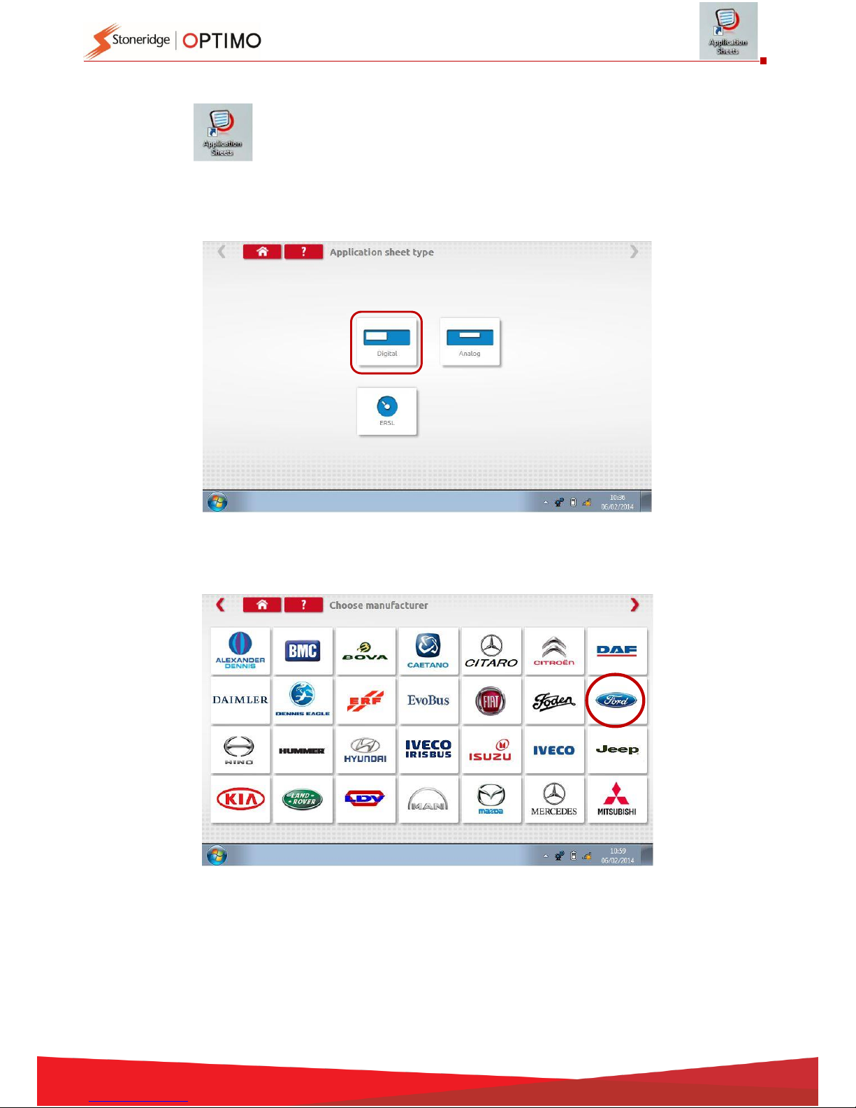
11. Application Sheets
Tapping details how to fit tachographs and Electronic Road Speed Limiters, ERSLs, to
different vehicle types.
Tap on type of application sheet required.
Tap appropriate manufacturer’s icon.
Page 37
37
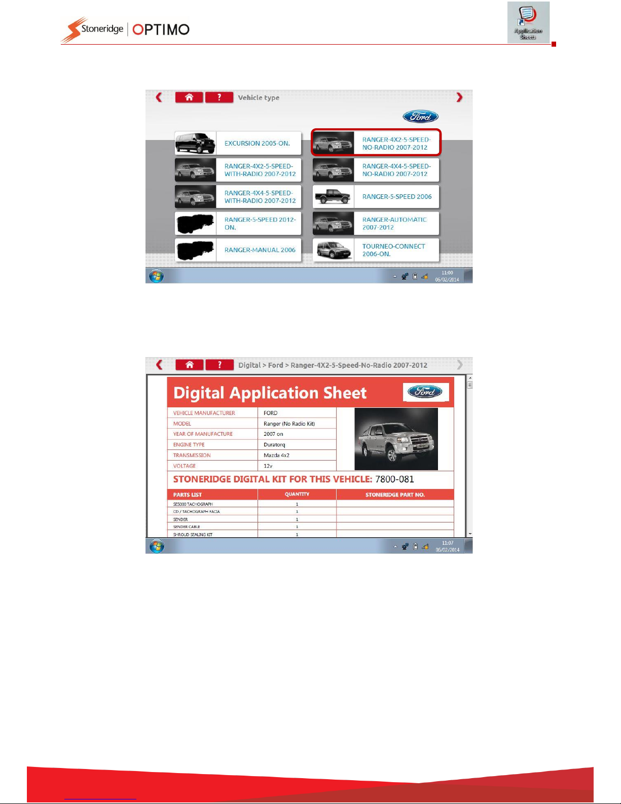
Tap correct vehicle model icon.
The application sheet is displayed which details the kit required, and in some cases instructions for
non-standard fits.
Page 38
38
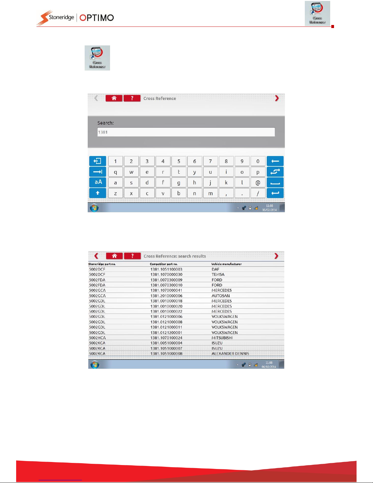
12. Cross Reference Tables
Tapping enables a user to cross reference tachographs or sensors with Stoneridge
equivalents.
Type the appropriate text or number for the search.
A list of all items containing the search text or number is displayed.
Page 39
39
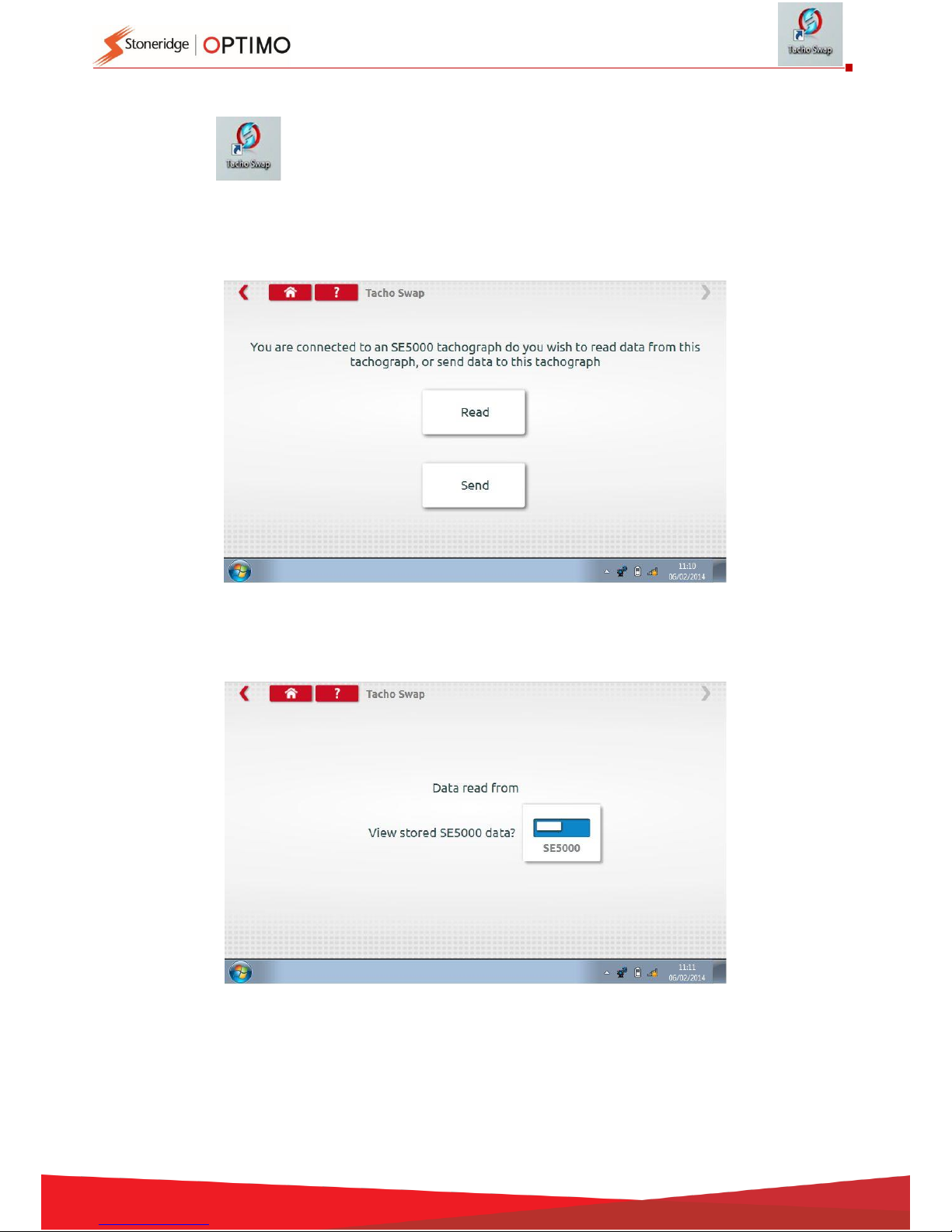
13. Tacho Swap
Tapping displays which tachograph is connected and gives options to “Read” or “Send”
data. This function enables removal and fitment of a tachograph in a seamless
process. For same tacho type exchange all parameters are transferred, for
cross type exchange only calibration parameters are transferred.
Note: the new tachograph must be configured prior to performing the tacho swap operation. For
digital tachographs this should be done before the unit is activated.
Tap “Read” and Optimo reads all data from the tachograph and gives an option to view stored data.
Page 40
40
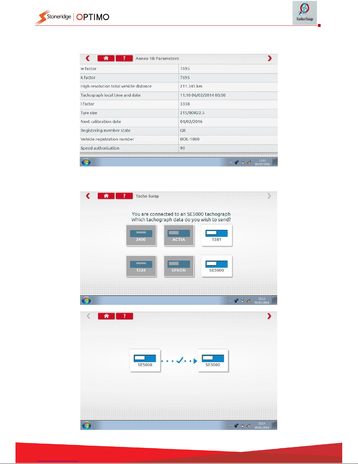
Tap the tachograph button to display stored information.
Note: You don’t have to view data before sending it.
Tapping “Send” displays which tachograph is connected, and options of which tachograph data to
send. Tap the appropriate button and a tick is displayed on completion.
Page 41
41
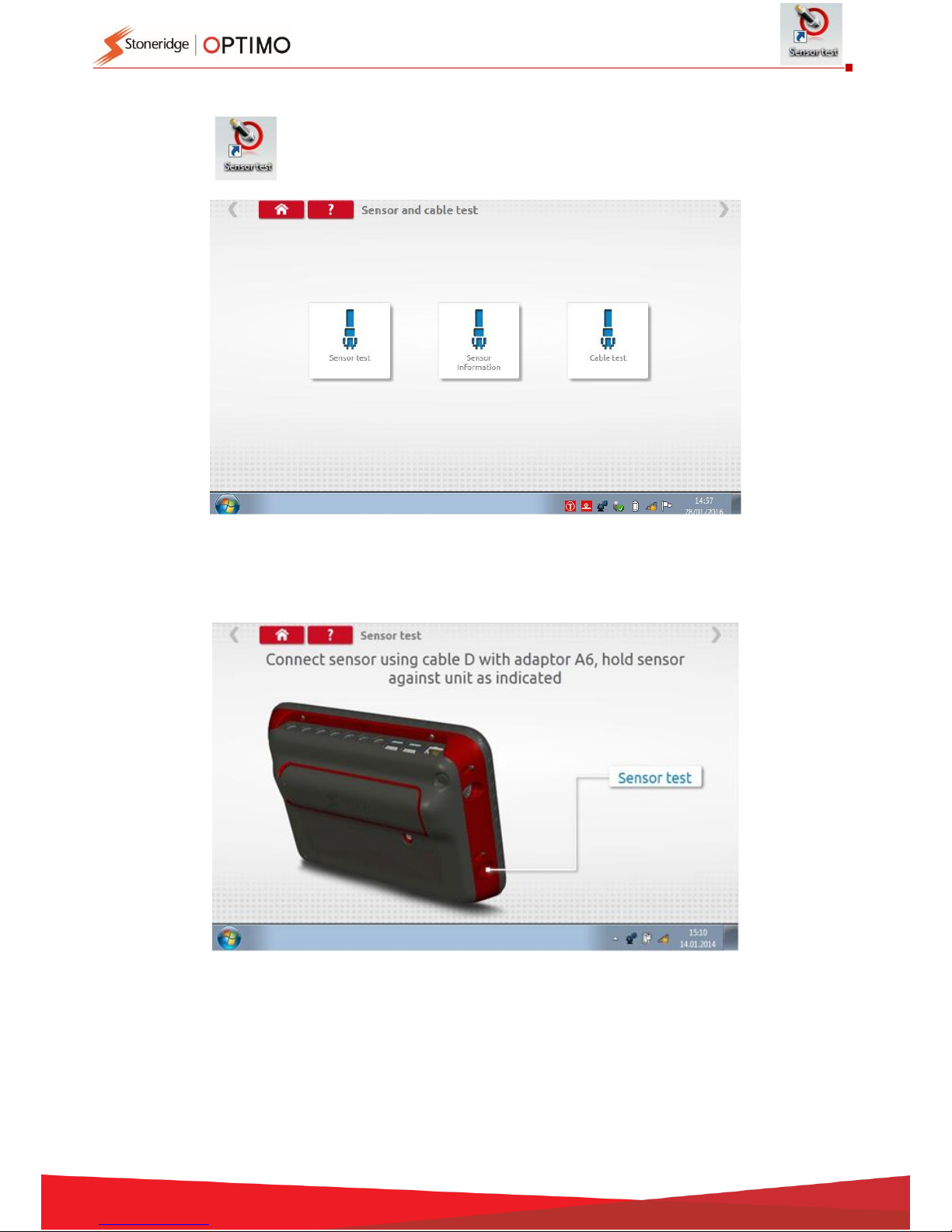
14. Sensor Test
Tapping provides the facility to test encrypted sensors or cables, or get information
from the sensor.
Note: Not available on Optimo Light or Optimo2
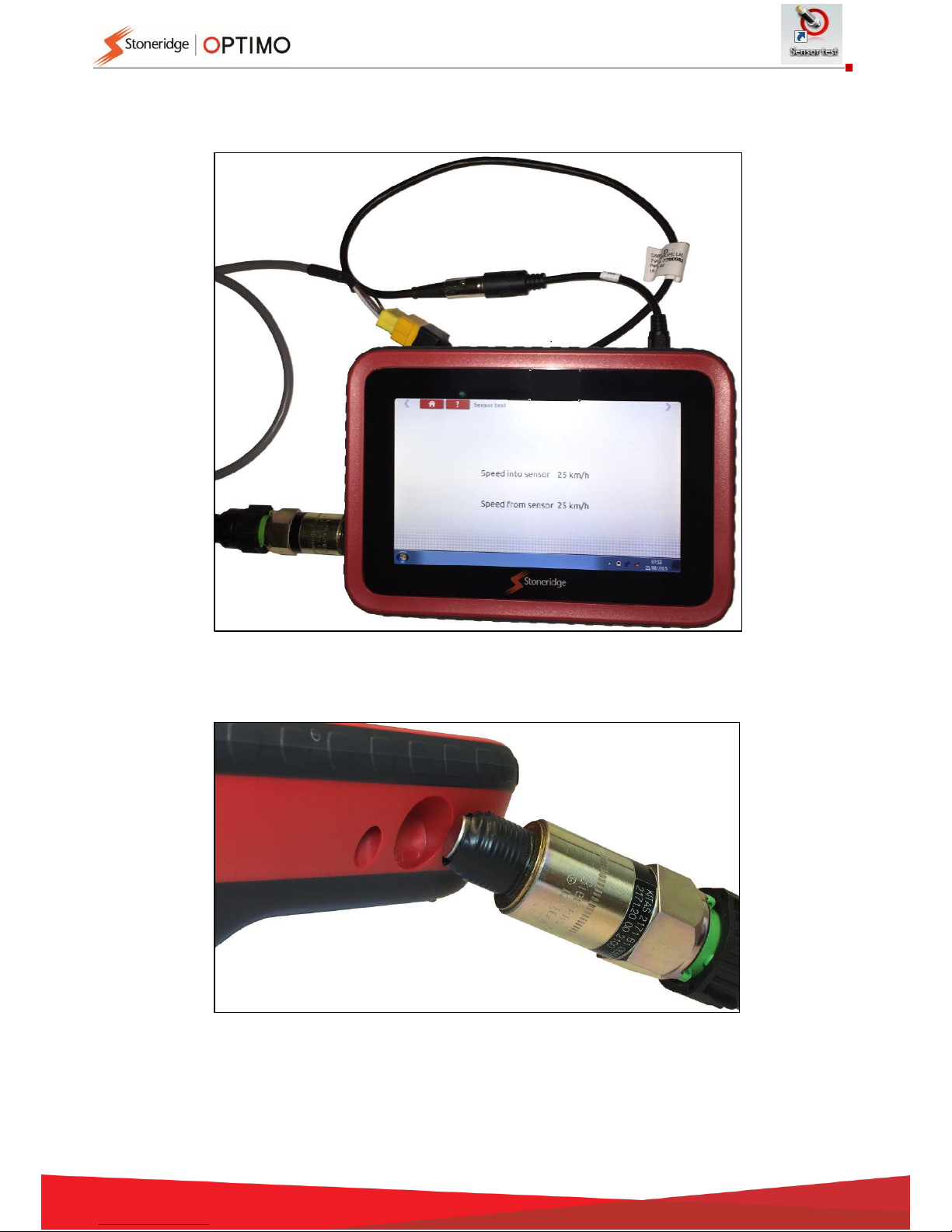
Tapping “Sensor test” displays instructions on which cables to use and how to connect to the
sensor.
Page 42
42
Connect as shown, press sensor into recess at bottom left of the device and the test begins. A
slight vibration is felt at the sensor and results are displayed.
Page 43

43
Tapping “Cable test” gives instructions to test encrypted cables. Connect as shown with the yellow
plug to Optimo via connector C1 and the other end terminated with plug C2. Tap the red arrow top
right and the result is displayed.
Page 44
44
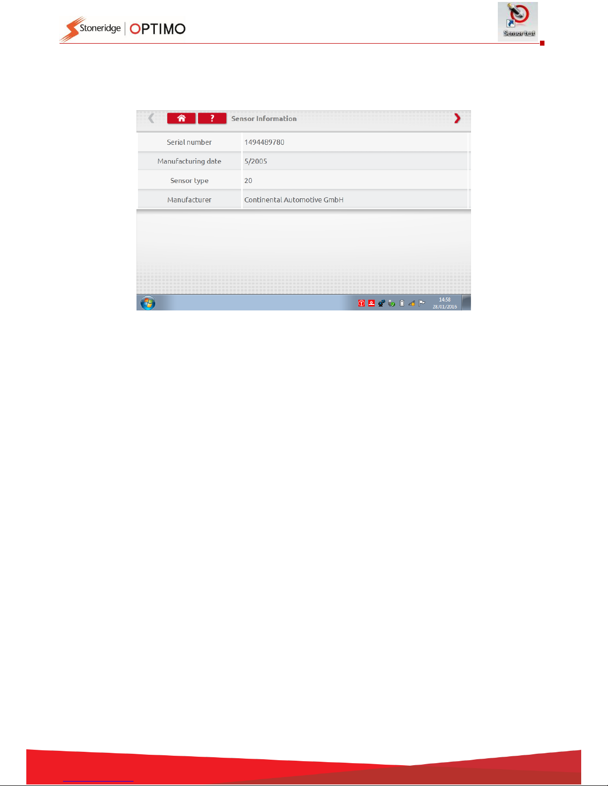
Tapping “Sensor Information” supplies information about the connected Sensor, such as Serial
number etc. Available on Optimo2 with purchase of new cable.
Page 45
45
15. Rolling Road Brake
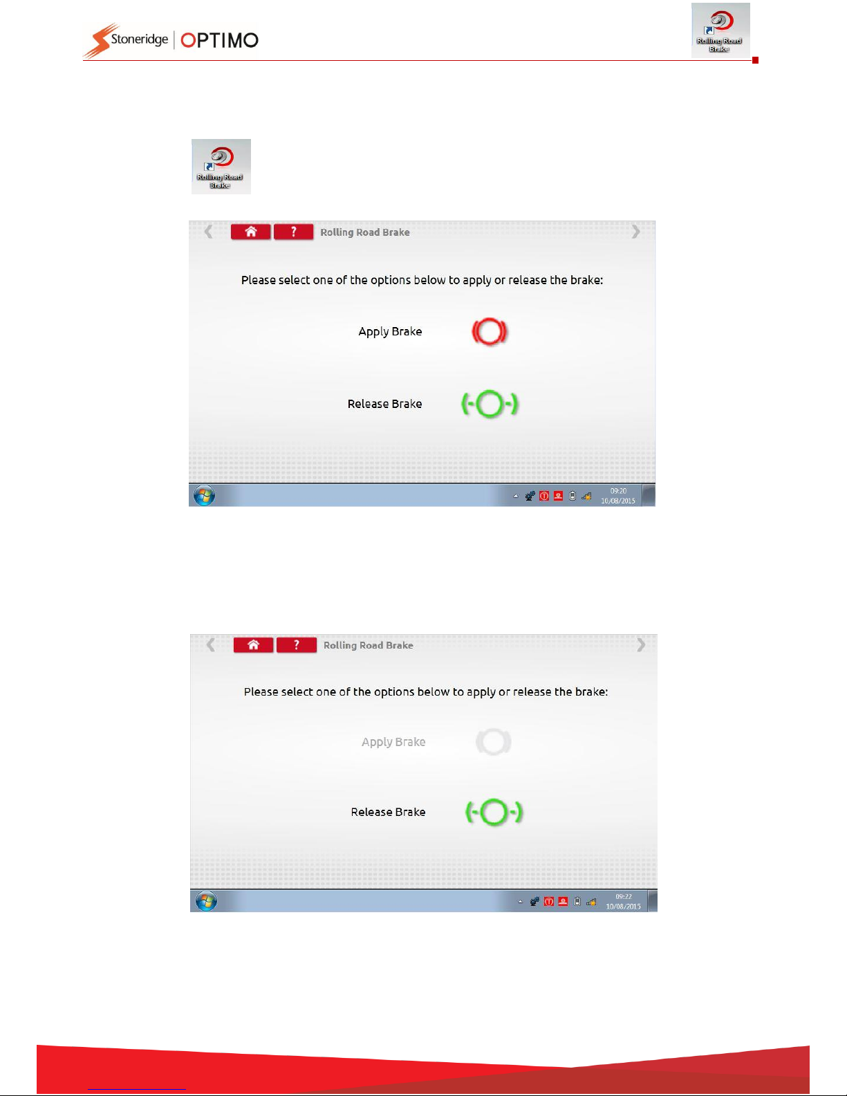
If your Rolling Road is connected wirelessly to Optimo the new Rolling Road Brake icon will appear.
Tapping enables a user to Apply or Release the Rolling Road brake via Optimo.
Initially both buttons will be active as the system will not know what state the brakes are currently
set to.
If you tap the Apply Brake button, it will apply the brakes to the rollers and that button will then be
inactive leaving only the Release Brake option, and vice versa.
Page 46
46
16. Product Upgrade
With links supplied from Stoneridge, download upgrades from the Web to a USB storage device.
Connect the Upgrade USB stick to an external port. When Optimo recognises the USB it may open a
pop up window, close this window.
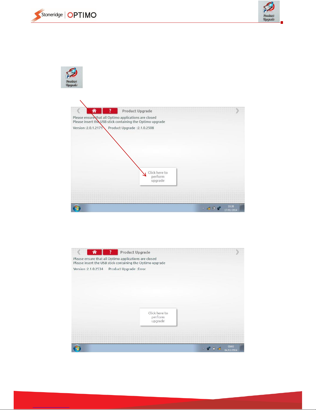
Tap and both current version and new version is displayed.
Tap the “upgrade” button and follow prompts.
“Error” is displayed if Optimo does not recognise the USB device, if no device present, or if it is the
wrong update. If this occurs, check the USB device inserted correctly and correct upgrade present.
Page 47
47
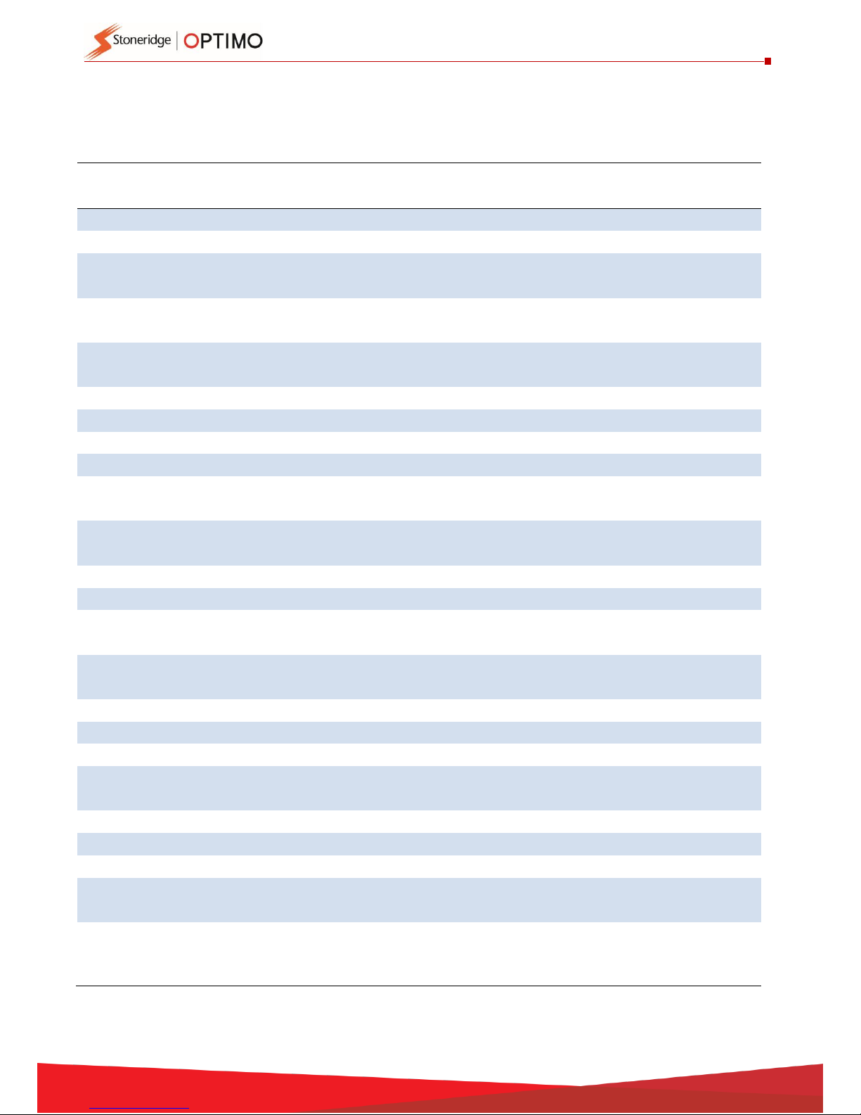
Annex A – Cable cross reference tables
This table shows a list of existing cables that can be used with Optimo when used in conjunction with the
appropriate adaptor cables supplied. Note: only A8 for Optimo Light
Part Number
Description
Cable
Identification
Current Din
Connector
Adaptor A
or B
7780-981
Tachograph Drive Lead
CABLE C
6 way
A-6
7780-982
Vehicle Sender Conn. Lead
CABLE D
6 way
A-6
7780-983
PPR/Engine Rev Calibration
Lead
CABLE E
6 way
A-6
7780-986
Serial Data Out Adaptor
Lead
CABLE F
Use with Cable H
A-4
7780-984
Jack Socket Connection
Lead
CABLE G
6 way
A-6
7780-989
Serial Data Conn Lead
CABLE H
4 way
A-4
7780-987
Adaptor Cable (1400)
CABLE K
6 way
A-6
7780-988
Adaptor Cable (1314)
CABLE L
6 way
A-6
7780-974
Motometer Pulser Adaptor
CABLE M
Use with Cable C
A-6
7780-980
Motometer Programming
Lead
CABLE N
8 way
A-8
7780-979
1319 Jack Socket Adaptor
Lead
CABLE O
Use with Cable G
A-6
7780-973
1319 Programming Lead
CABLE P
8 way
A-8
7780-975
Motometer Revs Adaptor
CABLE Q
Use with Cable G
A-6
7780-978
Flat Wire Cable Adaptor
8400
CABLE S
Use with Cable G
A-6
7780-977
Flat Wire Cable Adaptor
1314
CABLE T
Use with Cable H
A-4
7780-936
2400 Programming Lead
CABLE U
8 way
A-8
7780-956
2400 Canbus Data Lead
CABLE V
8 way
A-8
7780-952
MTCO Programming Lead
CABLE W
8 way
A-8
7780-955
2400 Serial Data Adaptor
Lead
CABLE X
Use with Cable H
A-4
7780-810
Digital Programming Lead
CABLE Z
8 way
A-8
7955-938
Clock Tester
8 way
A-8
7955-777
Flexi Switch
4 way
B
7780-948
Kienzle Laser Device
Adaptor
4 way
B
7500-008
Rolling Road Cable
4 way
B
Page 48
48
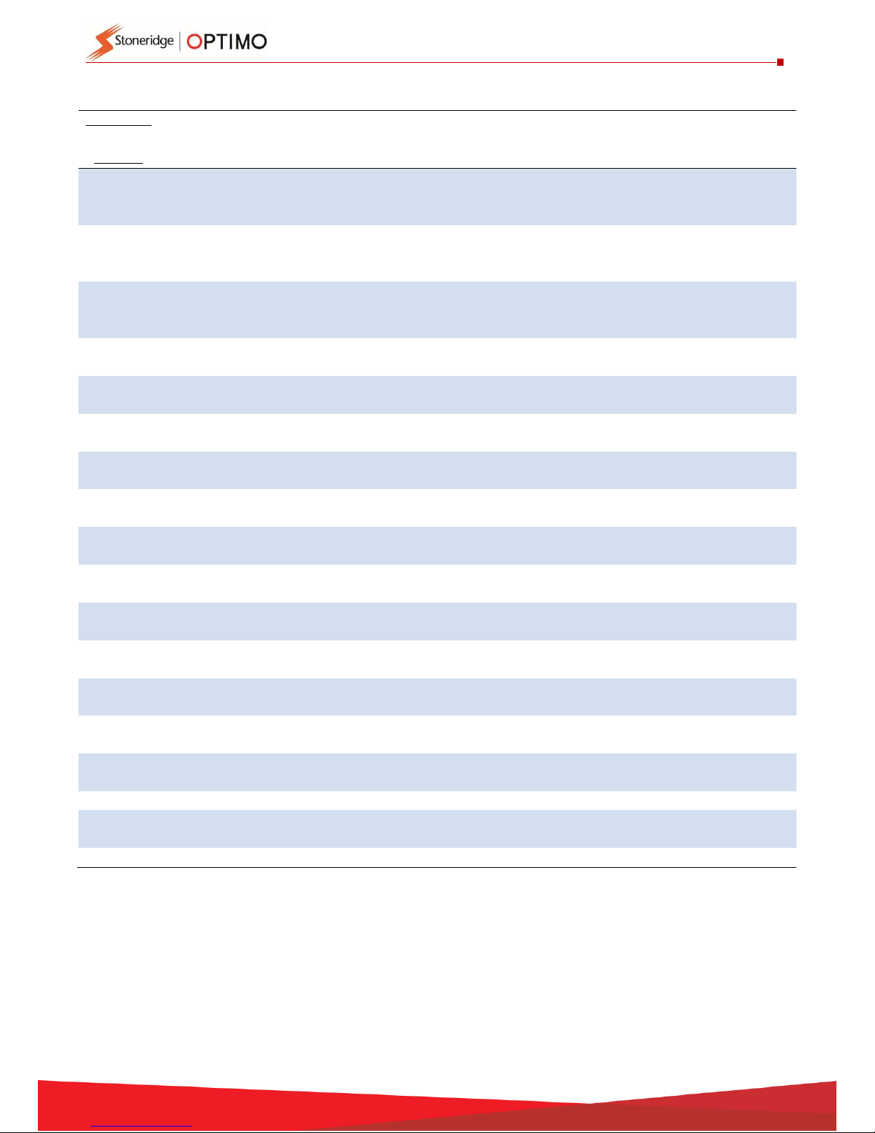
Available functions and required harnesses
Tachograph
Function
VR2400
VR8400
VR8300
VR1400
K1324
K1319
K1318
K1314
MotoMeter
EGK100
SE5000
DTCO
Smar-
tach
Rolling
Road
U or D
G+J or
D
G+J or D K
W or
D
G+O+J
G+J or
D
G+J or L N
Z or D
Z or
D
Z or D
Fixed Dist
#1
U or D
G+J or
D
G+J or D K
W or
D
G+O+J
G+J or
D
G+J or L N
Z or D
Z or
D
Z or D
Fixed Dist
#2
U or D
G+J or
D
G+J or D K
W or
D
G+O+J
G+J or
D
G+J or L N
Z or D
Z or
D
Z or D
Bench Test
C
G+S+J
or C
C K C or O
G+O+J
or C
G+S+J
or C
G+T+J
or L
C+M or N Z Z Z
Speed
Simulator
U or C
G+S+J
or C
C K W or
C
G+O+J
or C
G+S+J
or C
G+T+J
or L
C+M or N Z Z Z
RPM Pulse
Test
E E E - W - E - N - - - Clock Test
U
Clock
Tester
Clock
Tester
- W Clock
Tester
Clock
Tester
Clock
Tester
N Z Z Z Tacho
Control
U
G+J - -
W or C - - - N - - -
Identify
Tacho
U - - - W - - - - Z Z Z Read/Erase
DTCs
U - - - W - - - - Z Z
Z
Send All
Data
U
G+J - - W P - - N Z Z Z
Modify
Data
U - - - W P - - N Z Z Z Read All
Data
U - - - W P - - N Z Z Z Program
Tacho
-
G+J - - - - - - - - - -
k factor
Test
-
G+J - - - G+O+J
G+J
G+J - - - -
Pair / Test
- - - - - - - - - Z Z
-
Time /
Date
- - - - - - - - - Z Z
Z
Enter PIN
- - - - - - - - - Z -
-
Notes:
(1) Fixed Distance #2 also requires the Flexi Switch or light barriers.
(2) DIL Calculate, Tacho Select and Pulser Select do not require any connections
Page 49
49
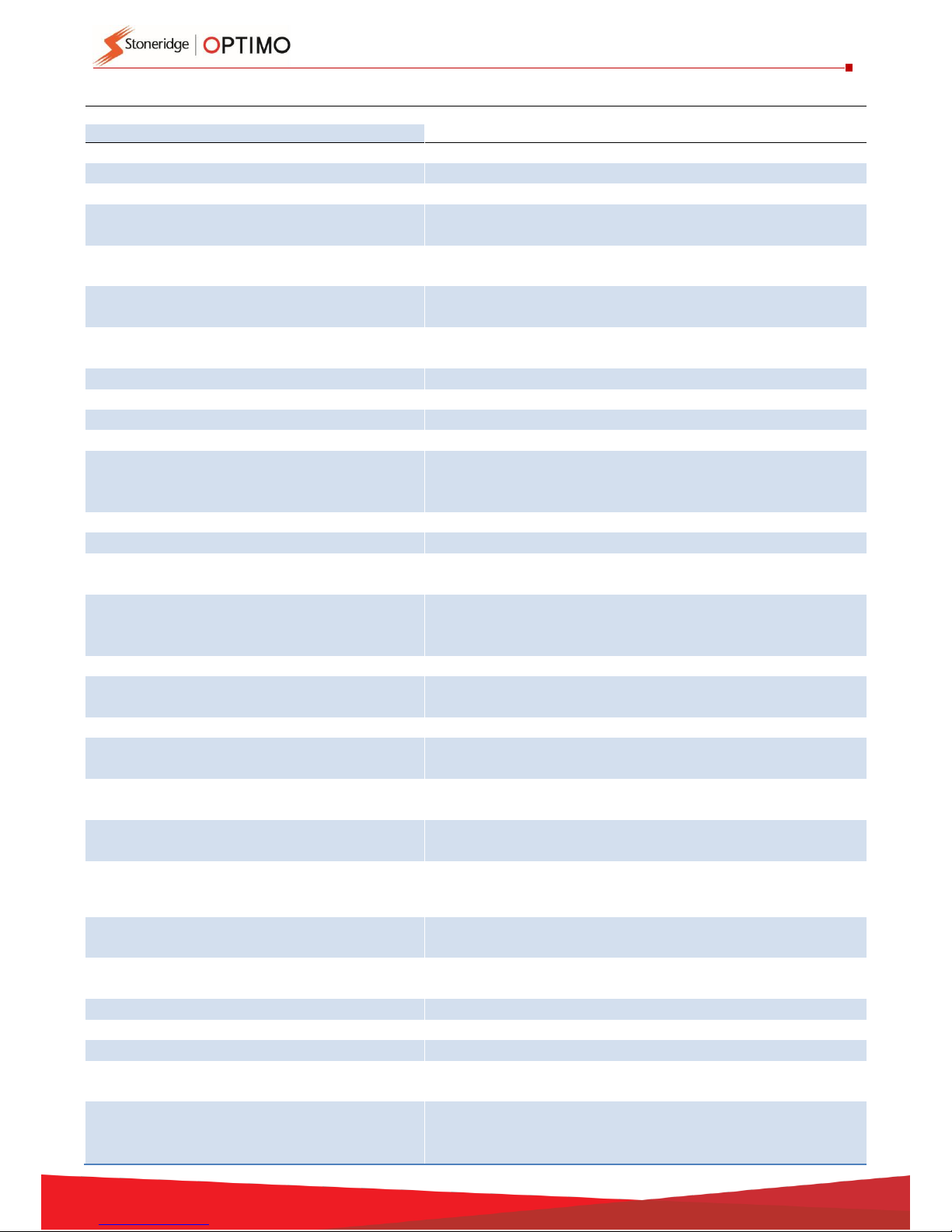
Annex B – Programmable Parameters
Programmable Parameters
Access
Read/Write
SE5000
VR
2400
DTCO
1381
Kienzle
1324
Actia
Efkon
Text displayed
Description
System Supplier Identifier
R X X X X X ECU Manufacturing Date
R X X X X X ECU Serial Number
R X X X X X
System Supplier ECU Hardware
Number
R X X X X X
System Supplier ECU Hardware
Version Number
R X X X X X
System Supplier ECU Software
Number
R X X X X X
System Supplier ECU Software
Version Number
R X X X X X
System Name Or Engine Type
R X X X X X
w-factor
Vehicle Characteristic w factor
R/W
X X X X X
X
k-factor
k factor
R/W
X X X X
X
Odometer
Total Vehicle Distance
R/W
X X X X X
X
Current time +
Current date +
Time offset
Time/Date
R/W
X X X X
X
l-factor
Tyre Circumference l factor
R/W
X X X X X X Tyre size
Tyre Size
R/W
X X X
X
Next Calibration
Date
Next Calibration Date
R/W
X X X
X
Vehicle
Registration
Nation
Registering Member State
R/W
X X X
X
VRN
Vehicle Registration Number
R/W
X X X
X
Speed
Authorised
Speed Authorised
R/W
X X X X
X
VIN
Vehicle Identification Number
R/W
X X X X X
X
CANBus
enabled
Can Enable on A-CAN
R/W
X X
CAN
Termination
CAN Termination on A-CAN
R/W
X
CAN trip reset
CAN Trip Reset Service Component
Id
R/W
X
CANBus type
Transmission Repetition Rate Of
TCO1 Message
R/W
X X X
X
Reset Heartbeat
Reset Heartbeat Message
R/W
X X X
X
O/P shaft factor
Pulses Per Revolution Of Output
Shaft
R/W
X X X X X
X
Backlight Select
Display Backlight Selection
R/W
X Illumination Lvl
Illumination Level
R/W
X Illumination Off
Illumination Offset
R/W
X
Illumination
Input
Illumination Input, (A2/CAN)
R/W
X
Speedo Output
factor
D6 Factor (speedometer OP
factor)
R/W
X X
Page 50

50
Programmable Parameters
Access
Read/Write
SE5000
VR
2400
DTCO
1381
Kienzle
1324
Actia
Efkon
Text displayed
Description
D6 pin function
D6 Pin Functions, (Speed Pulse
Output)
R/W
X X
D6 pin function
Pin D6
R/W
X
Filter pin B3
Filter - speed sensor signal pin (B3)
R/W
X
D5 pin function
D5 Pin Enabled, (Over Speed
Output)
R/W
X
D4 pin function
D4 Pin Functions, (General
Warning Output)
R/W
X X
D7 pin function
D7 Pin Enabled, (K-line Rear)
R/W
X C1 pin function
Settings off C1 output
R/W
X
Revs Input
C3/CAN
Revs Input, (C3/CAN)
R/W
X X
RPM Factor
Rpm Factor, (C3 factor)
R/W
X X X
Serial Data Out
Serial Data Output , (D8 Functions)
R/W
X X
Low speed Limit
Low Speed Limit
R/W
X X
Ignition Activity
Change
Activity change at Key on/off
R X
Definition Key
On/Off
Activity at ignition ON/OFF
R/W
X X
Pref. Language
Default Language
R/W
X Service delay
Service Delay Calendar Time Based
R/W
X X X X Install date
ECU Installation Date
R/W
X X X X
Pre-Next
Calibration
Days left until next calibration
R/W
X
Pre-Overspeed
Pre overspeed
R/W
X Display function
Display function
R/W
X
RD Activity
Status
Remote download activation
status
R X
RD Card Writing
Remote download card writing
R/W
X
RD CAN
Configuration
Remote download C-CAN
Configuration
R/W
X
Show Remote
Download
Show remote download
R/W
X
CAN wake up
CAN wake up
R/W
X
2nd source of motion
R X
2nd source of motion, allowed
offset
R/W
X
2nd source of motion, speed diff.
R/W
X
2nd source of motion, CAN msg.
R/W
X
C3 speed factor
R/W
X Add. Event Rec.
Use Of D1 D2 Registration
R/W
X Eng. Speed Rec.
Use Of Engine Speed Registration
R/W
X X VRESD
Vu Ranges Engine Speed Data
R/W
X
Vehicle Speed
Rec.
Use Of Vehicle Speed Registration
R/W
X
VRVSD
Vu Ranges Vehicle Speed Data
R/W
X
Maximum
Warranty
Maximum Warranty Time
R X
Page 51

51
Programmable Parameters
Access
Read/Write
SE5000
VR
2400
DTCO
1381
Kienzle
1324
Actia
Efkon
Text displayed
Description
Warranty Valid
Time
Warranty Validity Time
R X
Warranty Time
Warranty Time
R/W
X
Number of
writes Warranty
Number of writings to Warranty
Time
R X
Activation Time
Time of activation
R X
Dimming Input
Dim mode
R/W
X
CAN Dimming
Input
Can Dim mode
R/W
X
Diming
Parameters.
Dim parameters
R/W
X
Dim preset
record
Dim-mode preset
R/W
X
Kline Speedo
R/W
X
Pulses per engine revolution
R/W
X
CANbus RPM
R/W
X
RPM Display
R/W
X
Odometer leading 0s
R/W
X
Overspeed flash
R/W
X
Overspeed
R/W
X
Customer Type
R/W
X
Dual Axle
R/W
X
Dual Axle ratio
R/W
X
Crew auto duty
R/W
X
7 day eject PIN
R/W
X
Ignition-on recording
R/W
X
DTCs enabled
R/W
X
4th chart trace
R/W
X
Analogue Revs
R/W
X
Rev Band Limits - Low Power Band
R/W
X
Rev Band Limits - Economy Band
R/W
X
Rev Band Limits - Poor Economy
R/W
X
CANBus type
CANbus Type. This is part of ECU
Hardware Number
R/W
X
Repair Shop Code Or Tester Serial
Number
W X X X
Programming Date
W X X X
Calibration Equipment Serial
Number OR
Calibration Repair Shop Code
W X X X
Calibration Date
W X X X
Calibration Equipment Software
Number
W X X X
Page 52
52
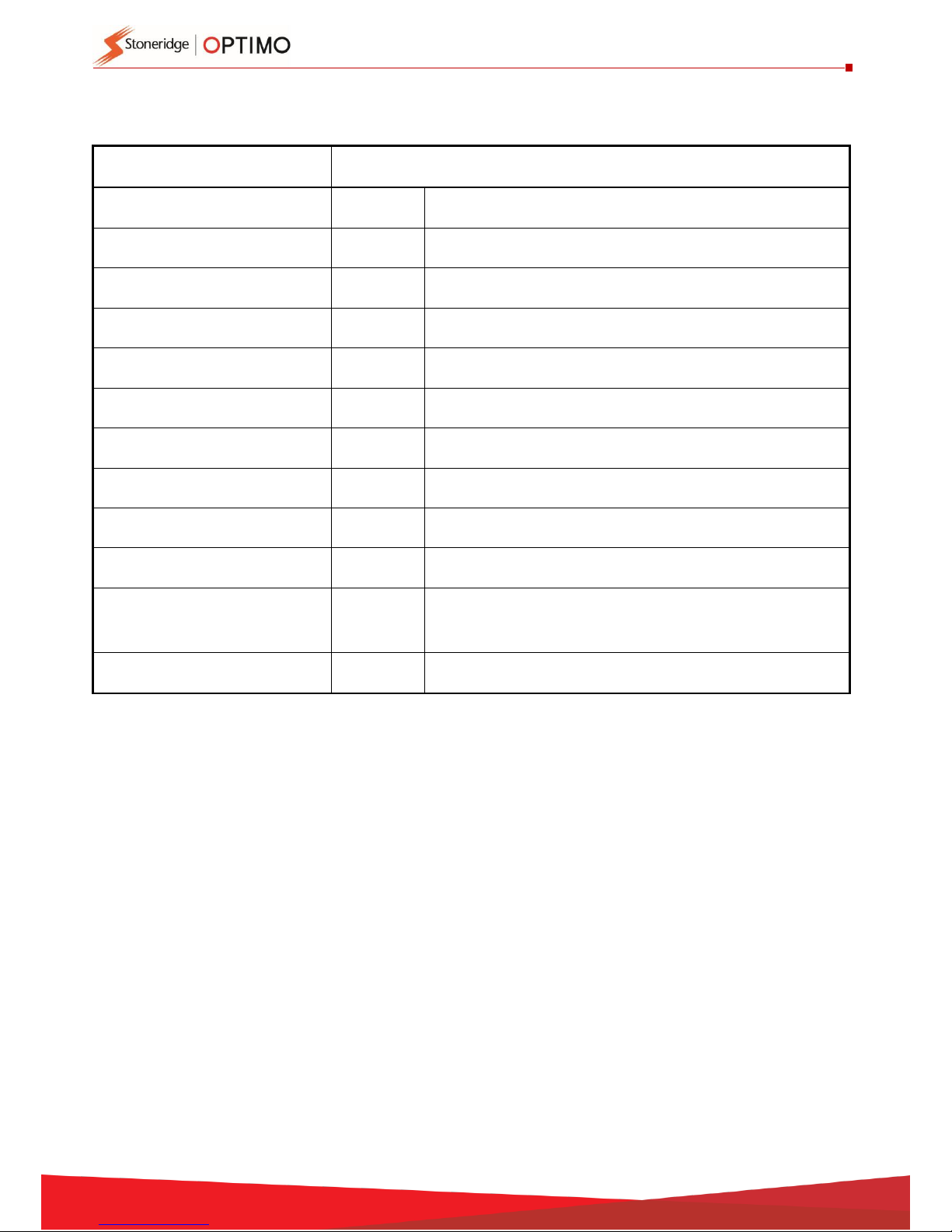
Annex C – Optimo Error Codes
Application Codes
APPLICATION
Error Code
MK3 Programmer
0x00**
Codes 01 to 10 / 1F / 20 to 29 / D0 to FF are valid
SE5000 Configuration System
0x01**
Codes 01 to 10 / 1F / D0 to FF are valid
Tachograph Swap
0x02**
Codes 01 to 10 / 1F / D0 to FF are valid
Sensor Test
0x03**
Codes 01 to 10 / 1F are valid
Application Sheets
0x04**
Codes D0 to FF are valid
Cross Reference
0x05**
Codes D0 to FF are valid
Workshop Settings
0x06**
Codes D0 to FF are valid
Calibration
0x07**
Codes D0 to FF are valid
Product Upgrade
0x08**
Code C1 is Valid
Taximeter
0x09**
DTCO1381 Configuration
System
0x0A**
Wireless Brake
0x0B**
Page 53
53
Specific Error Codes
Error
Code
Category
Error
Code
Category
0x**01
Comms Timeout
0x**20
Tacho Value Out Of Range
0x**02
Transfer Aborted Returned
0x**21
Upload Not Accepted
0x**03
General Reject
0x**22
Requested Data Unavailable
0x**04
Security Access Denied
0x**24
Tacho Not In Correct Mode
0x**05
Request Out Of Range Returned
0x**25
Data Parameter Not Accepted
0x**06
Service Error
0x**26
Pin Timeout Has Occurred
0x**07
Tacho Type Incorrect
0x**27
No Card Detected In Tacho
0x**08
Can Or Serial Data Timeout
0x**28
Incorrect Card Type In Tacho
0x**09
IF Board Comms Error
0x**29
Invalid Pin Entered Into Tacho
0x**0A
PC Comms Port Error
0x**C1
Product Upgrade Error
0x**0B
Function Not Supported ,
0x**D0
Cannot Connect To Or Retrieve Data From
App Database
0x**0C
Renesas Frequency Calibration Error
0x**D1
Data Not Found In App Database
0x**0D
Invalid Key
0x**DF
General Data Error
0x**0E
Number Attempts Exceeded
0x**E0
C8051 Init Error
0x**0F
Required Time Delay Not Expired
0x**E1
C8051 Wrong Device ID
0x**10
Sub Not Supported Invalid Format
0x**E2
C8051 Not Blank
0x**11
Sub Not Supported Inactive Session
0x**E3
C8051 Flash Update Failed
0x**12
Svc Not Supported Inactive Session
0x**E4
IF Board Firmware Upgrade Error
0x**13
Svc Not Supported Inactive Diag Mode
0x**EF
IF Board Firmware Error
0x**14
Transfer Data Suspended
0x**F0
Unit Not Calibrated Error
0x**15
General Programming Failure
0x**F1
Logging Error
0x**16
Incorrect Msg Len Or Invalid Format
0x**F2
Calibration Result Error
0x**17
Bad Checksum Illegal Byte Count Block
Transfer
0x**F3
Touch Screen Software Not Found
0x**18
Target Address Not This Device
0x**FE
EULA Not Signed
0x**19
Data Received From Unknown Source
Address
0x**FF
General Error
 Loading...