

Page 1
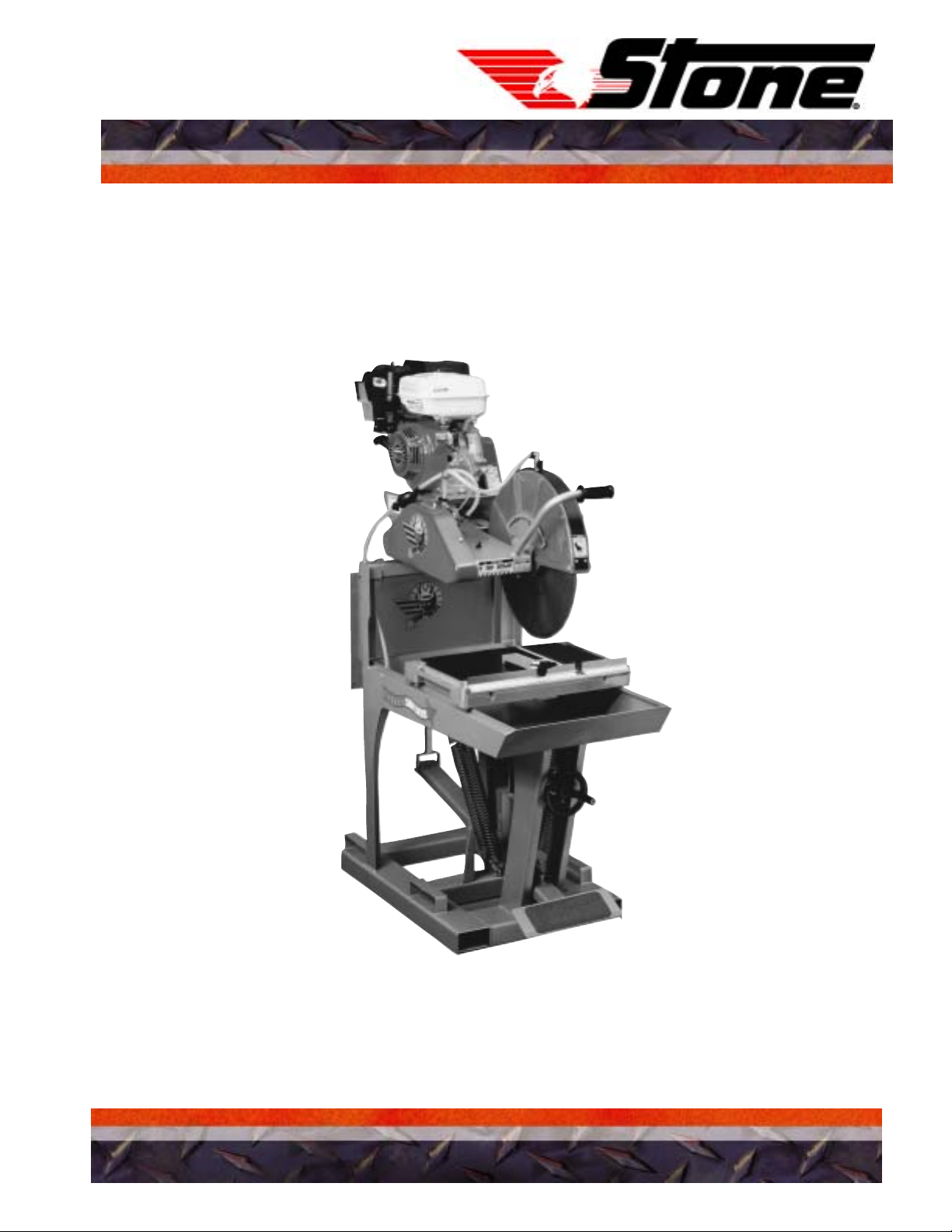
OPERATOR MANUAL
MODEL: MS1 and MS2
SAW DEVIL
®
Portable / Professional Masonry Saw
A 100% employee-owned American manufacturer
REVISION: B 2/2003 P/N 56420
Page 2

Page 3

TABLE of CONTENTS
TABLE OF CONTENTS ........................................................................................ 3
USER INFORMATION.......................................................................................4-5
Foreword .................................................................................................................. 4
Service Data ............................................................................................................. 4
Warranty .................................................................................................................. 5
HEALTH & SAFETY ..........................................................................................6-8
Safety......................................................................................................................... 6
Safety Precautions .................................................................................................. 7-8
TECHNICAL DATA..........................................................................................9-13
Specifications ............................................................................................................ 9
Electrical Power Supply Connection....................................................................... 10
Sound and Vibration Measurements ....................................................................... 10
Torque Chart - Imperial........................................................................................... 11
Torque Chart - Metric.............................................................................................. 12
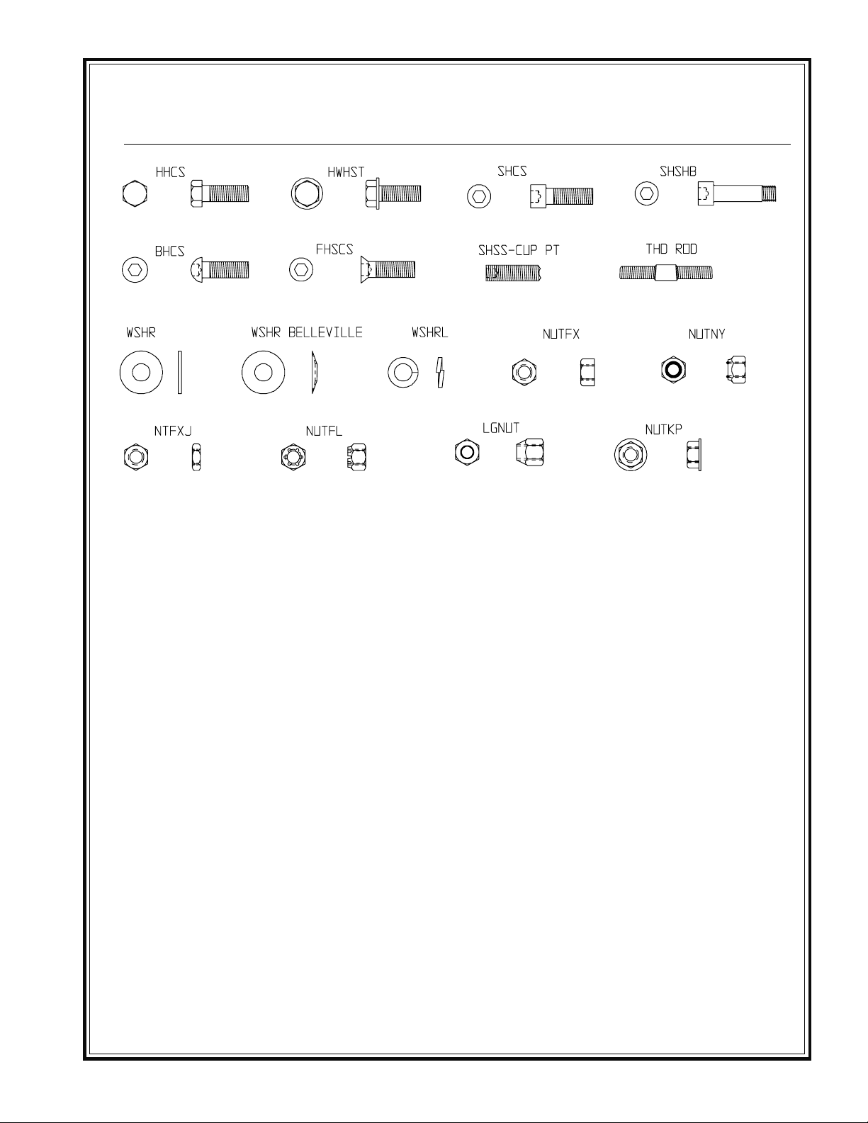
Hardware Key.......................................................................................................... 13
Masonry Saws
OPERATIONS..................................................................................................14-15
Introduction ............................................................................................................. 14
Installation Instructions ........................................................................................... 15
Operating Instructions ............................................................................................. 15
MAINTENANCE ............................................................................................. 16-22
Important ................................................................................................................. 16
Cleaning/Before Storing/Daily ........................................................................... 17-18
Service Check List................................................................................................... 18
Troubleshooting..................................................................................................19-21
Service Record ........................................................................................................ 22
California Proposition 65................................................................................... IBC
- 3 -
Page 4
USER INFORMATION
Foreword
These instructions include:
Safety regulations
Operating instructions
Maintenance instructions
These instructions have been prepared for
operation on the construction site and for
the maintenance engineer.
These instructions are intended to simplify
operation of the machine and to avoid
malfunctions through improper oper ation.
Observing the maintenance instructions will
increase the reliability and service life of the
machine when used on the construction
site and reduce repair costs and
downtimes.
Always keep these instructions at the place
of use of the machine.
Only operate the machine as instructed.
Observe the safety regulations as well as
the guidelines of the civil engineering trade
association. Observe the safety rules for the
operation and the pertinent regulations for
the prevention of accidents.
Stone Construction Equipment, Inc. is not
liable for the function of the machine when
used in an improper manner or f or other
than the intended purpose.
1. Machine Type: ______________________________
Machine S/N: _______________________________
2. Engine Type: _______________________________
Engine S/N: ________________________________
3. VIN: ______________________________________
4. Purchase Date: ______________________________
5. Dealer/Distributor Information:
Name: _____________________________________
Address: ___________________________________
__________________________________________
Phone #: ___________________________________
Fax #: _____________________________________
6. Battery
Manufacturer: ______________________________
Battery Type: _______________________________
Battery S/N: ________________________________
Location of above information:
1. Information on S/N tag.
2. Information on engine tag.
Operating errors, improper maintenance
and the use of incorrect operating materials
are not covered by the warranty.
The above inf ormation does not extend the
warranty and liability conditions of business
of Stone Construction Equipment, Inc.
Stone Construction Equipment, Inc.
P.O. Box 150, Honeoye, New York 14471
Phone: (800) 888-9926
Fax: (585) 229-2363
3. Information on S/N tag - if applicable.
4. Date you purchased machine.
5. Dealer machine was purchased from.
6. Information on battery and battery warranty
card.
- 4 -
Page 5

L i m i t e d W a r r a n t y
The Manufacturer warrants that products manufactured shall be free from defects in material and
workmanship that develop under normal use for a period of 90 days for concrete vibrators and electric
pumps, one year for Rhino®, Bulldog®, WolfPac Rollers™, trowels, Stompers®, saws, forward plates,
engine powered pumps, Lift Jockey™, Mortar Buggy™ and 6 months for all other products from the
date of shipment. The foregoing shall be the exclusive remedy of the buyer and the exclusive liability of
the Manufacturer. Our warranty excludes normal replaceable wear items, i.e. gaskets, wear plates, seals,
O-rings, V-belts, drive chains, clutches, etc. Any equipment, part or product which is furnished by the
Manufacturer but manufactured by another, bears only the warranty given by such other manufacturer.
(The Manufacturer extends the warranty period to “Lifetime” for the drum bearings and seals for the mortar
mixers, and agrees to furnish, free of charge, the bearings and seals only upon receipt of the defective
parts. The warranty is two years for eccentric bearings on the forward plate compactors, mortar and plaster
mixer drums, trowel gearboxes and five years on the Bulldog trench roller eccentric bearings.) A Warranty
Evaluation Form must accompany all defective parts. Warranty is voided by product abuse, alterations,
and use of equipment in applications for which it was not intended, use of non-manufacturer parts, or
failure to follow documented service instructions. The foregoing warranty is exclusive of all other warranties
whether written or oral, expressed or implied. No warranty of merchantability or fitness for a particular
purpose shall apply. The agents, dealer and employees of Manufacturer are not authorized to make
modification to this warranty, or additional warranties binding on Manufacturer. Therefore, additional
statements, whether oral or written, do not constitute warranty and should not be relied upon.
The Manufacturer’s sole responsibility for any breach of the foregoing provision of this contract, with respect
to any product or part not conforming to the Warranty or the description herein contained, is at its option (a)
to repair, replace or refund such product or parts upon the prepaid return thereof to location designated
specifically by the Manufacturer. Product returns not shipped prepaid or on an economical transportation
basis will be refused (b) as an alternative to the foregoing modes of settlement - the Manufacturer’s dealer
to repair defective units with reimbursement for expenses, except labor, and be reviewed with the
Manufacturer prior to repair. A Warranty Evaluation Form must accompany all warranty claims.
Except as set forth hereinabove and without limitation of the above, there are no warranties or other
affirmations which extends beyond the description of the products and the fact hereof, or as to operational
efficiency, product reliability or maintainability or compatibility with products furnished by others. In no
event whether as a result of breach of contract or warranty or alleged negligence, shall the Manufacturer
be liable for special or consequential damages including but not limited to: Loss of profits or revenues, loss
of use of the product or any associated product, cost of capital, cost of substitute products, facilities or
services or claims of customers.
No claim will be allowed for products lost or damaged in transit. Such claims should be filed with the carrier
within fifteen days.
Effective July 2002.
Stone Construction Equipment, Inc. • 8662 Main Street, P. O. Box 150 • Honeoye, NY 14471-0150
Phone: 1-800-888-9926 • 1-585-229-5141 Fax: 1-585-229-2363
www.stone-equip.com • e-mail: [email protected]
- 5 -
P/N 51018 F-7080 7/2002
Page 6

HEALTH & SAFETY
SAFETY
These machines are designed to carry out the function of flat sawing material of the non-cohesive, bituminous and granular varieties.
Safety
If used correctly they will pro vide an eff ective and safe
means of sawing and meet the appropriate performance standards.
It is essential that the driver/operator of the machine
is adequately trained in its safe operation, be authorized to operate it, and have sufficient knowledge of
the machine to ensure that it is in full working order,
before being put to use.
- 6 -
Page 7
HEALTH & SAFETY
Safety Precautions
Before using this equipment, study this entire manual
to become familiar with its operation. Do not allow
untrained or unauthorized personnel, especially children, to operate this equipment. Use only factory
authorized parts for service.
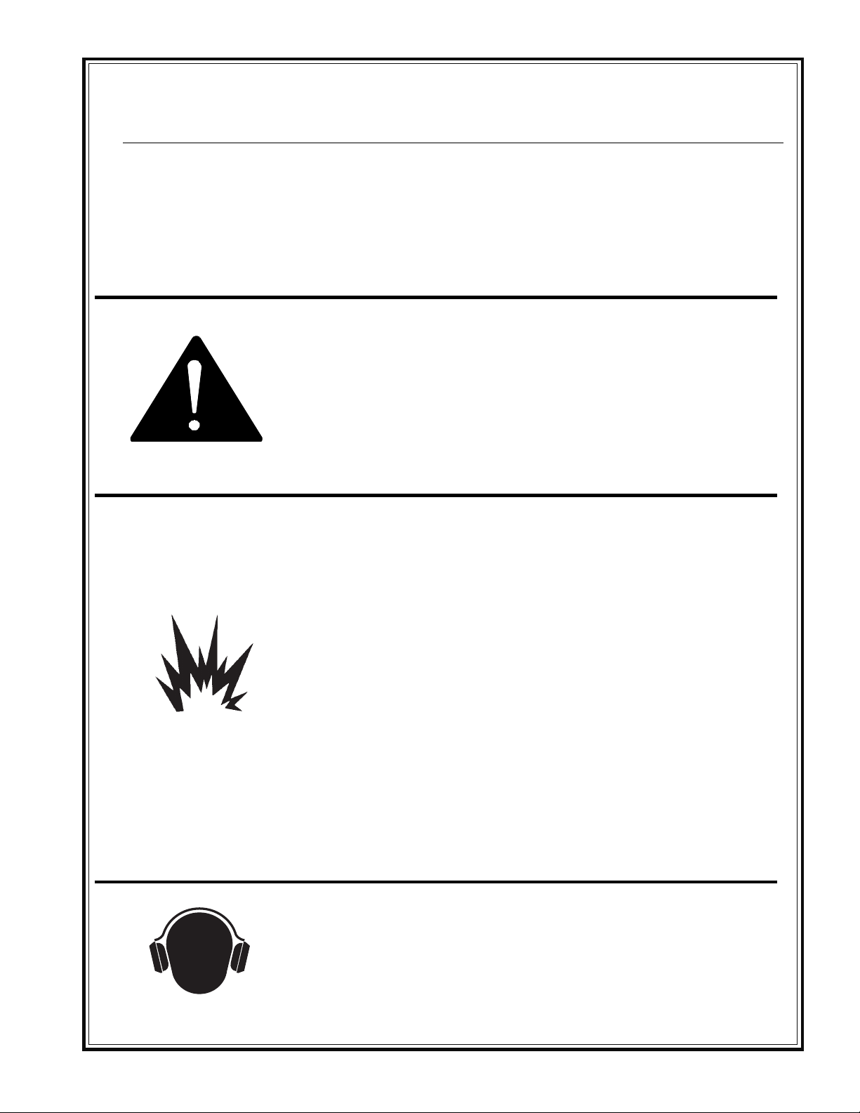
This notation appears before warnings in the text. It means that the
step which follows must be carried out to avoid the possibility of
personal injury or death. These warnings are intended to help the
technician avoid any potential hazards encountered in the normal
service procedures. We strongly recommend that the reader takes
advantage of the information provided to prevent personal injury or
injury to others.
USE COMMON SENSE WHEN HANDLING FUELS
Transport and handle fuel only when contained in approved safety
container.
When warning decals are destroyed or missing, contact the Manufacturer immediately at 1-800-888-9926
for replacement. For the safety of yourself and others,
it is imperative that the following rules are observed.
Failure to do so may result in serious injury or death.
Do not smoke when refueling or during any other fuel handling operation.
Do not refuel while the engine is running or while it is still hot.
If fuel is spilled during refueling, wipe it off from the engine immediately
and discard the rag in a safe place.
Do not operate the equipment if fuel or oil leaks exist - repair immedi-
ately.
Never operate this equipment in an explosive atmosphere.
Ear protection required when operating this equipment.
- 7 -
Page 8
HEALTH & SAFETY
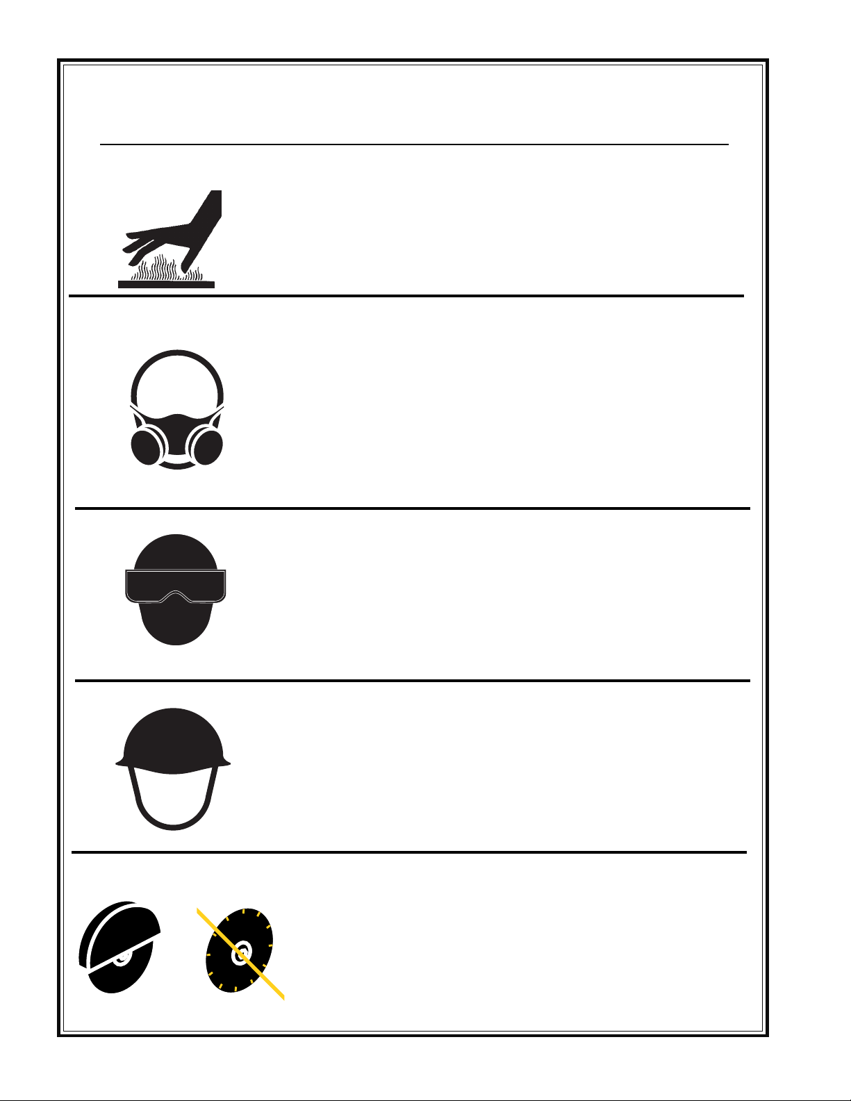
Avoid contact with hot exhaust systems and engines.
Allow engine to cool before performing any repairs.
Never operate unit in a poorly ventilated or enclosed area.
Avoid prolonged breathing of exhaust gases.
Safety Precautions
Eye protection required when operating this equipment.
Head protection required when operating this equipment.
Never operate this equipment without all guards in place.
- 8 -
Page 9
TECHNICAL DATA
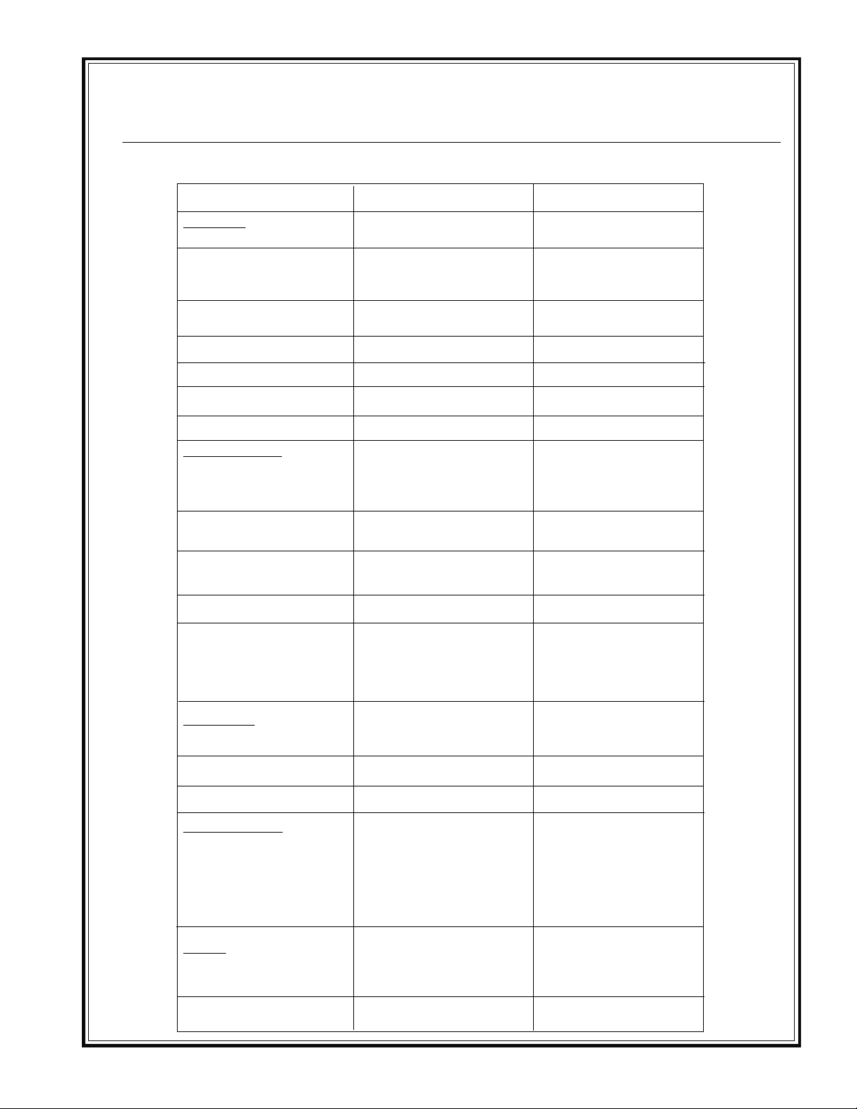
Specifications - Block Saws
Model
Dimensions
Weight (kg)
Dimensions (LxWxH)† (cm)
Blade Capacity (cm)
Cut Depth (cm)
Water Pan Dimensions (LxW)
Conveyor Table (L x W)
Table Height
Operating System
Engines (kW)
Air Filter
Engine (Hz)
MS1
190 lbs (87.3)
37" x 21" x 33"
(94 x 54 x 84)
14" (35,6)
5" w/ 14" blade (12.7)
31" x 18" (78 x 46)
10" x 19" (25.4 x 48)
35" (89) (with leg kit)
1 1/2 hp Baldor (1.2)
2 hp Baldor (1.5)
5.5 hp Honda cyclone(4.1)
Dry Element (Cyclone on
Honda)
3450 rpm (57.5) Electric
3600 rpm (60) Gas
MS2
445 lbs (216)
48" x 25" x 71"
(122 x 64 x 180)
62.5" high on electric
14", 20" (35,6 / 50.8)
20" standard
5" w/ 14" blade (12.7)
8" w/ 20" blade (20.3)
40" x 24" (101 x 61)
16.5" x 25" (42 x 64)
35" (89)
3 hp Baldor (2.3) - 230V only
5 hp Baldor (3.8) - 230V only
9hp Robin cyclone (6.7)
8 hp Honda cyclone (5.9)
11 hp Honda cyclone (8.2)
Dry Element (Cyclone on
Honda and Robin)
3450 rpm (57.5) Electric
3600 rpm (60) Gas
Voltage
Water System
Performance
Blade Shaft Bearings
size (mm)
Blade Arbor (mm)
Arbor Height
Standard Features
Options
Warranty
115 - 230
Corrosion resistant electric
water pump on electric
models, Belt driven pump on
gas models, Brass fittings
Greasable pillow block
sealed 1" (25,4)
1" (25,4)
11.5" (29.2)
Stay-level cast aluminum
blade guard with 210
blade coverage, 45o/90o miter
guide, cast aluminum con-
veyor cart, padded blade
lever
115V or 230V plugs, Folding leg
kit, Foot pedal kit,
Splash guard
1 year limited
o
of
230
Corrosion resistant electric
water pump on electric
models, Belt driven pump on
gas models, Brass fittings
Greasable pillow block
sealed 1" (25,4)
1" (25,4)
24" (61)
Stay-level cast aluminum
blade guard with 210o of
blade coverage, 45o/90
miter guide, cast aluminum
conveyor cart, bi-directional
forklift brackets,
heavy-duty hand crank,
padded blade lever
230V plug,
Splash guard,
14" or 20" Blade guard
1 year limited
o
- 9 -
Page 10
TECHNICAL DATA
Power Supply/Sound Chart
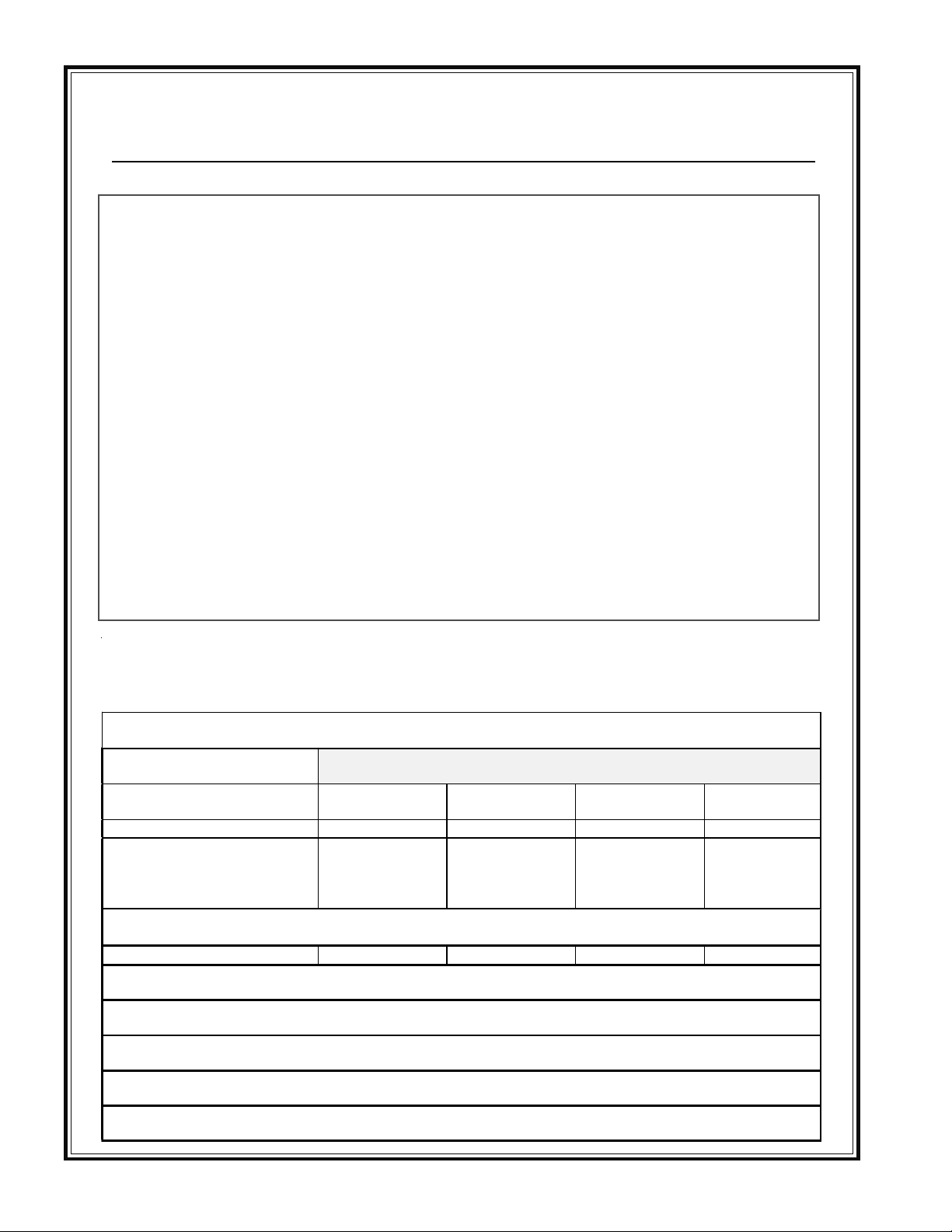
Electrical Power Supply Connection
Connecting wires or extension cords should be as short as possible and one piece. In no case should the
connecting wires or extension cords be longer than shown in the following chart.
Motor Voltage 50” 75” 100”
1-1/2 HP 115 No. 10 No. 10 No. 8
1-1/2 HP 230 No. 14 No. 14 No. 14
2 HP 115 No. 10 No. 8 No. 6
2 HP 230 No. 12 No. 12 No. 12
3 HP 230 No. 10 No. 10 No. 10
5 HP 230 No. 8 No. 8 No. 8
Sound and Vibration Measurements
Sound Pressure Values as measured are per the following:
Noise 1 Model/Configuration
Sound Pressure MS1
Electric 14”
at operator’s ear
1.6 meters above floor
1.0 meter from su r face of
machine at 9 o’clock from
operator
RMS acceleration on the handle were measured per the following:
meter/sec
Sound and vibration values have been taken in accordance to the EEC machine regulation (edition
93/68/EEC)
Sound Pressure measurements were taken with Simpson model 886-2 type 2 meter, calibrated 2/21/97
Acceleration measurements were taken with Quest Tech model VI-100 meter, calibrated 4/17/96
Sound and vibration measurements were obtained with machine operating at maximum engine speed of
3450 RPM.
Units had blades mounted and measurements were taken out of cuts.
2 RMS
89dBA 100dBA 97dBA 103dBA
85dBA 96dBA 98dBA 104dBA
1.05 1.10 0.84 1.31
MS1
Gas 14”
MS2
Electric 20”
MS2
Gas 20”
- 10 -
Page 11
TECHNICAL DATA
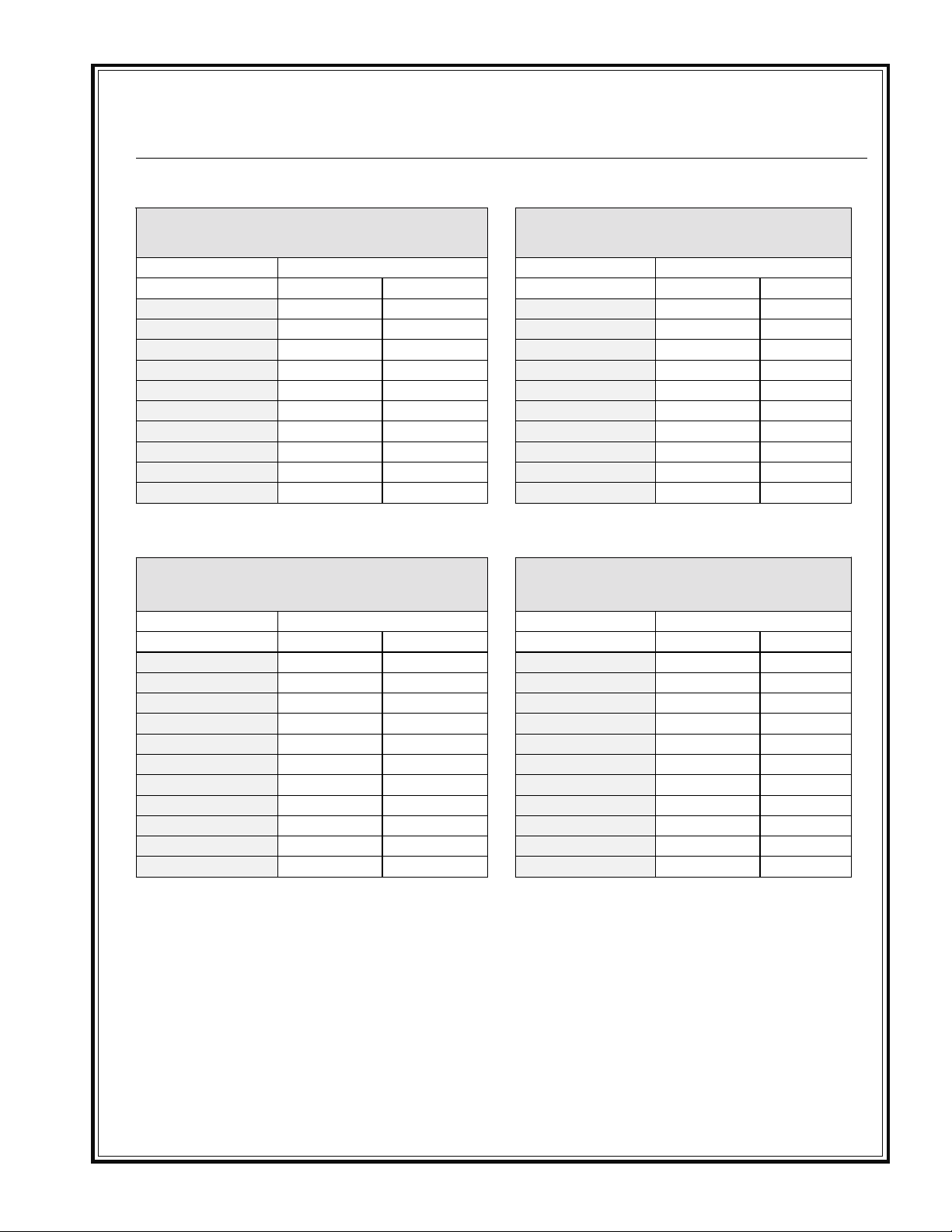
Torque Chart - Imper ial
SAE GRADE 5
Coarse Thread, Zinc-Plated
SIZE TORQUE SIZE TORQUE
ft. lbs. Nm ft. lbs. Nm
1/4 - 20 (.250) 681/4 - 20 (.250) 912
5/16 - 18 (.3125) 13 18 5/16 - 18 (.3125) 18 24
3/8 - 16 (.375) 23 31 3/8 - 16 (.375) 33 45
7/16 - 14 (.4375) 37 50 7/16 - 14 (.4375) 52 70
1/2 - 13 (.500) 57 77 1/2 - 13 (.500) 80 108
9/16 - 12 (.5625) 82 111 9/16 - 12 (.5625) 115 156
5/8 - 11 (.625) 112 152 5/8 - 11 (.625) 159 215
3/4 - 10 (.750) 200 271 3/4 - 10 (.750) 282 382
7/8 - 9 (.875) 322 436.5 7/8 - 9 (.875) 454 615
1 - 8 (1.000) 483 655 1 - 8 (1.000) 682 925
Coarse Thread, Zinc-Plated
SAE GRADE 5
Fine Thread, Zinc-Plated
SIZE TORQUE SIZE TORQUE
ft. lbs. Nm ft. lbs. Nm
1/4 - 28 (.250) 7101/4 - 28 (.250) 10 14
5/16 - 24 (.3125) 14 19 5/16 - 24 (.3125) 20 27
3/8 - 24 (.375) 26 35 3/8 - 24 (.375) 37 50
7/16 - 20 (.4375) 41 56 7/16 - 20 (.4375) 58 79
1/2 - 20 (.500) 64 87 1/2 - 20 (.500) 90 122
9/16 - 18 (.5625) 91 123 9/16 - 18 (.5625) 129 175
5/8 - 18 (.625) 128 173 5/8 - 18 (.625) 180 244
3/4 - 16 (.750) 223 302 3/4 - 16 (.750) 315 427
7/8 - 14 (.875) 355 481 7/8 - 9 (.875) 501 679
1 - 12 (1.000) 529 717 1 - 12 (1.000) 746 1011
1 -14 (1.000) 541 733 1 -14 (1.000) 764 1036
SAE GRADE 8
SAE GRADE 8
Fine Thread, Zinc-Plated
t-chrt_i.doc
- 11 -
Page 12
TECHNICAL DATA
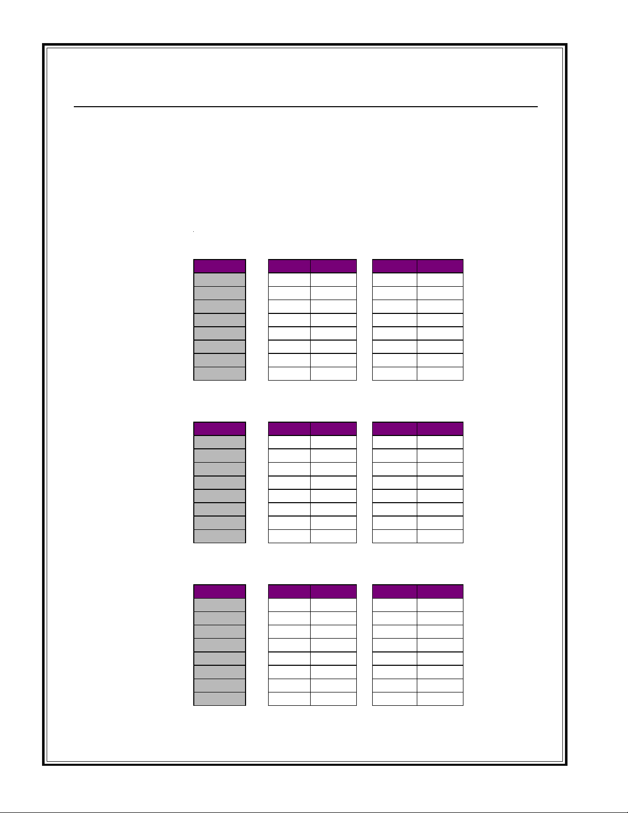
Torque Chart - Metric
Monthly, inspect all hardware on this equipment and engine/motor. Loose hardware can contribute to early component
failure and poor performance. Use the torque chart below as a general guideline and keep all hardware tight.
Note: Some hardware is used to retain parts that have to move freely for correct operation of this unit. The hardware for
these items should be snug enough to prevent excessive play, yet loose enough to allow the parts to pivot freely.
Property Class 8.8
ZINC-PLATED
SIZE Nm ft. lbs. Nm ft. lbs.
M6 9.9 7 10 7
M8 24 18 25 18
M10 48 35 49 36
M12 83 61 88 65
M14 132 97 140 103
M16 200 148 210 155
M20 390 288 425 313
M24 675 498 720 531
Coarse Thread Fine Thread
Property Class 10.9
ZINC-PLATED
SIZE Nm ft. lbs. Nm ft. lbs.
M6 14 10 14 10
M8 34 25 35 26
M10 67 49 68 50
M12 117 86 125 92
M14 185 136 192 142
M16 285 210 295 218
M20 550 406 600 443
M24 950 701 1000 738
Coarse Thread Fine Thread
Property Class 12.9
ZINC-PLATED
SIZE Nm ft. lbs. Nm ft. lbs.
M6 16.5 12 16.5 12
M8 40 30 42 31
M10 81 60 82 60
M12 140 103 150 111
M14 220 162 235 173
M16 340 251 350 258
M20 660 487 720 531
M24 1140 841 1200 885
Coarse Thread Fine Thread
Conversion Factor: 1 ft. lb. = 1.3558 Nm
- 12 -
Page 13
TECHNICAL DATA
Hardware Key
VR005A
ZN = ZINC PLATED
BLK = BLACK OXIDE FINISH
- 13 -
Page 14

OPERATIONS
INTRODUCTION
Introduction
Congratulations on your purchase of Stone's Saw
Devil™! You've made an excellent choice! The
Sawdevil has been specifically designed as the ideal
machine for the professional contractor who is engaged in concrete and asphalt flat sawing.
Stone Saw Devils™ are used for the primary
purpose of “flat” sawing. This type of sawing is
described as “flat” because the pavement is cut
somewhere close to a horizontal plane. It is the
most common type of diamond blade cutting.
Concrete saws in the industry are available in a
variety of types, sizes and styles. They range from
manual or self propelled in horsepower from 772hp. It is possible to cut both concrete (green or
cured, with or without rebar) or asphalt with a
concrete saw.
The Stone Saw DevilTM line represents the most
popular sizes and configurations on the market.
You’ll find manual or self propelled models
powered by gasoline engines ranging from 7hp 20hp capable of accepting blades of up to 18 inches
in diameter. They are designed to cut horizontal
slabs to depths of a maximum of 6 5/8 inches.
The Saw Devil™ is manufactured to the strictest specifications and inspection procedures. If any material
or manufacturing defects are found, return the tag on
the machine with assembler's signature and your findings to the manufacturer. We want to know when a
product is less than perfect. We also welcome any
and all input on how the product may serve you better.
The Stone Masonry Saw Line includes the most
popular configurations of saws for cutting block,
pavers, brick and most all masonry products. They
are available in portable and professional models
from 1-1/2hp to 5hp electric and gas, and 8hp and
11hp gasoline block house professionals.
You will find a Stone Saw DevilTM to fit a wide
variety of job applications.
Upon receipt of your Saw Devil™, CAREFULLY
CHECK FOR ANY FREIGHT DAMAGE. Any
damage should be immediately reported to the carrier and a claim registered.
- 14 -
Page 15

OPERATIONS
Installation Instructions
Remove the loose bolts in the cross tube. Raise the
fitting bar and connecting link to the upright positions so that the bolt may be installed and tightened.
Before placing the cutting head on the frame, make
sure that the cross bar rests are clean. Install (2)
12mm bolts and washers into the cross bar from
behind and at an upward angle.
Fasten the “Quick Disconnect” fitting on the connecting link to the ball on the blade guard by pulling
back on the spring loaded sleeve while it is placed
on the ball, then release it. The length of the link has
been factory set for the best blade position. Adjustment may be modified should other settings be
desired by loosening the lock nuts at the front and
rear and lengthening or shortening the length of the
link. Attach linkage to tilt head with hardware
provided, making sure linkages are free to move.
Installation/Operating Instructions
3HP saw set for 230 volt operation can be supplied
with a NEMA L6-20P plug on the pigtail. The
extension cord will require an L620C plug to make
the proper connection. Bear in mind, for the user to
meet the National Electric Code, the plug on the
extension cord should also be a NEMA number L620P, and the receptacle in the box into which this
will be plugged should be a NEMA number L6-20.
ALWAYS MAKE SURE THAT
THE SAW IS CONNECTED TO
A PROPERLY GROUNDED
ELECTRIC OUTLET.
Electric motors of any make can burn out completely
when the voltage supply falls 10% below the voltage
rating of the motor. Use proper heavy duty fuses in
the circuit.
Operating Instructions
For wet cutting, fill the water reservoir pan to within
one inch of the top. Be sure the water pump intake
is fully covered by water at all times. Keep the
pump intake free of accumulated sludge, and other
foreign material.
According to the National Electric Code, no three
wire 115v/230v electric motor can safely be wired to
provide a 110v pigtail for accessories. Therefore, we
ask that a properly grounded extension cord from a
GFI (ground fault interrupt) outlet be provided to
operate the electric water pump supplied with your
saw. The pump plug must be kept out of contact
with water both in the water pan and on the ground.
Stone single phase masonry saws are furnished with
the correct approved NEMA configuration plug on
the motor pigtail—the plug appropriate for the
voltage to which the motor is set. It will be necessary to provide a matching NEMA configuration
connector on the extension cord into which the
pigtail from the motor is plugged. For example: a
- 15 -
Page 16
MAINTENANCE
IMPORTANT
THE PERSON ATTEMPTING ANY OF THE
FOLLOWING MAINTENANCE TASKS, MUST BE
AUTHORIZED TO DO SO AND HAVE READ AND
Important Note
NDERSTOOD ALL SECTIONS WITHIN THIS
U
MANUAL
- 16 -
Page 17

MAINTENANCE
Cleaning/Before Storing/Daily
Have your electrician check the voltage at the motor
when the saw is cutting.
All Stone single phase masonry motors are equipped
with manual reset overload. When the overload
trips, turn the switch to the OFF position, allow the
motor to cool for 5 to 10 minutes, then push the reset
button. A click indicates reset.
CLEANING
At the end of each day’s use, clean the sludge from
the saw. Flush water through the pump and water
hoses every night.
BEFORE STORING
Before the saw is stored in the warehouse to wait for
the next job, use a wire brush to remove hard, caked
sludge. Clean and thoroughly lubricate moving parts
so when the saw is taken to the next job it is ready to
operate at top efficiency.
Check the extension wire size per chart in the
Technical Data section of this manual. Undersized
wires will burn out expensive motor. Use 230 volts
wherever possible.
If you have motor problems, contact your dealer (or
Stone directly in an emergency) for the name of your
nearest Authorized Service Dealer. If the motor is
under warranty, sending it to a Non-Authorized
Service Dealer voids the warranty.
DAILY
Keep the drive belt tight! Do not operate on low
voltage! Full voltage is essential to economical
operation. Always use 230 volts where available,
with a heavy duty extension cord. Have an electrician check the incoming voltage at the saw motor.
The blade must fit the arbor snugly, especially
diamond blades, otherwise pounding will occur,
seriously damaging the blades. If the arbor shoulder
is grooved where the diamond blade has bound in
the cut while the shaft has continued to turn, the
arbor must be replaced or the blade life will be
severely shortened.
The blade flanges must be full diameter—minimum
4”. Replace worn down flanges at once as undersized flanges shorten blade life and cause breakage.
Flanges should be clean and free of nicks and burrs.
Check the conveyor cart condition regularly.
Replace wheels and wood inserts frequently.
Be certain the cutting head is correctly aligned.
Misalignment through handling damage or transporting the saw with the cutting head on the frame can
seriously affect blade life. Check blade mounted,
with square against cutting table, vertical and
horizontal.
Replace noisy bearings at once! Worn bearings will
very quickly destroy the blade.
Flush clean water through the pump and spray the
assembly every night. This prolongs the pump and
blade life.
Blade shaft bearing should be tight--no free play
side-to-side or up-and-down.
Check oil levels, wiring, hoses, air filters, wheels
and lubricate machine daily.
All guards in place and secure. All fasteners tight
and secure.
Check pulley alignment using straight edge. All
pulleys have (2) set screws and require thread
locking loctite.
Drive belts must be tight! Power goes from the
motor to the arbor shaft—when belts are loose,
power is lost. Replace worn belts without delay.
Replace belts in sets only.
The slurry that accumulates in the bottom of the
water reservoir pan is as abrasive as a cutting
compound, and , if it accumulates heavily, will
shorten the life of the water pump and of the blades.
- 17 -
Page 18

Daily Continued/Service
MAINTENANCE
Clean the water reservoir pan at least once a day—
twice a day in heavy cutting—and refill with clean
water. Run clean water through your saw at the end
of each day to extend the life of pumps and other
components.
Grease blade shaft bearings daily.
Never transport a masonry saw with the cutting head
in position on the frame. The severe pounding and
bouncing can knock the head out of alignment.
ALL SAWS
• All gas saws set Engine RPM at 3600 +0 / -100
(no load).
• Check blade clamp hub face run-out with
indicator and magnetic chuck. Run-out not to
exceed .015”.
Check List
• On gas units make sure kill switch is functional
while running.
• Disconnect spark plug or unplug unit when
servicing unit.
• Check belt tension:
• MS1 Electric & Gas Belt deflection = .21
inches at 2.5 lbs. for used belt and 3.0 lbs for
new belt.
• MS2 Electric & Gas Belt deflection = .19
inches at 3.5 lbs. for used belt and 4.5 lbs for
new belt.
• Grease all pillow blocks.
• All guards in place, all hardware tight.
• Apply Never-Seize to acme screw.
• Check cutting tables wheels are tight and
rotating.
• Belts and pulleys in line.
- 18 -
Page 19
MAINTENANCE
Troubleshooting
PROBLEM
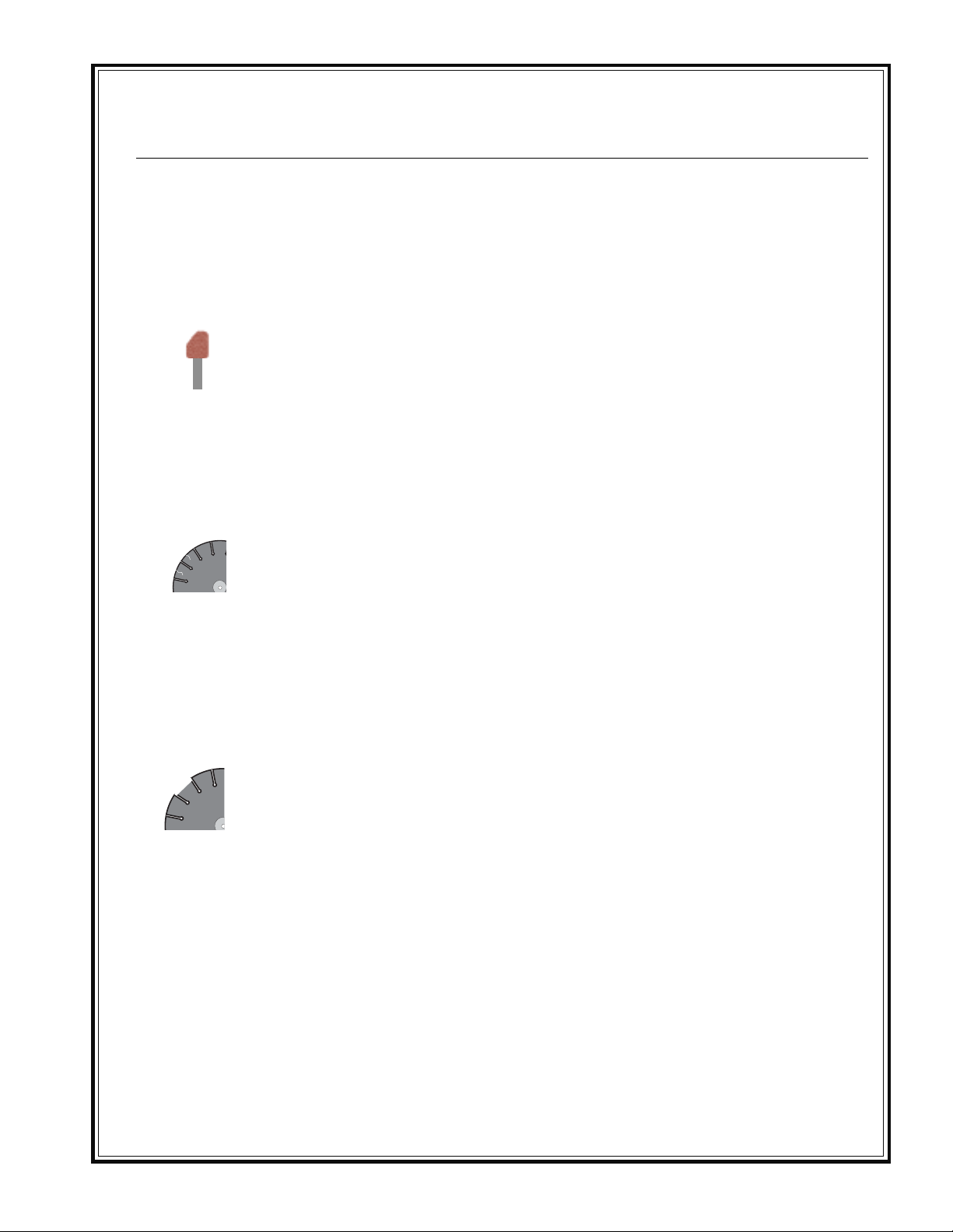
UNEVEN SEGMENT WEAR
SEGMENT CRACKS
• (In wet cutting) Insufficient water (usually on
one side of blade).
• Equipment defects also can cause the
segments to wear unevenly.
• Saw head is misaligned.
• Blade is too hard for material being cut.
REMEDYCAUSE
• Flush water system.
• Check flow to both sides of blade.
• Replace bad bearings, worn arbor
shaft or misalignment to spindle.
• Check alignment for squareness,
both vertically and horizontally, of
the saw blade.
• Use a blade with a softer bond/
matrix.
SEGMENT LOSS
• Blade overheats because of lack of
coolant (water or air).
• Core is worn from undercutting.
• Defective collars/flanges set blade out of
alignment.
• Blade is too hard for material being cut.
• Blade is cutting out of round, causing a
pounding motion.
• Improper blade tension.
• (Wet Cutting) Check water lines.
Make sure flow is adequate on
both sides of blade and there are
no blockages. Use sufficient water
to flush out the cut.
• (Dry Cutting) Run blade free of cut
periodically to air cool.
• Clean collars/flanges or replace if
they are under recommended
diameter.
• Use proper blade specification for
material being cut.
• Replace worn bearings; realign
blade shaft or replace worn blade
mounting arbor.
• When ordering blades match shaft
speed of saw.
• Check spindle speed to ensure
blade is running at correct RPM.
• Avoid twisting or turning blade in
the cut.
- 19 -
Page 20
MAINTENANCE
Troubleshooting
PROBLEM
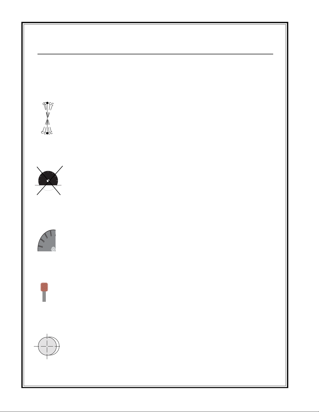
BLADE WOBBLES
BLADE WILL NOT CUT
CAUSE
• Blade is on a damaged or worn saw.
• Worn collar.
• Blade runs at an incorrect speed.
• Collar /flange diameters are not identical.
• Blade is bent as a result of dropping or
twisting.
• Blade is too hard for material being cut.
• Blade has become dull.
• Blade does not cut material it was
specified for.
REMEDY
• Check for bad bearings, bent shaft,
or worn mounting arbor.
• Check collars/flanges to make sure
they are clean, flat and of correct
diameter.
• Set engine at proper rpm.
• Use proper size blade collar s/
flanges.
• DO NOT USE bent blade. Contact
blade manufacturer .
• Select proper blade for material
being cut.
• Sharpen by cutting on softer
abrasive material to expose
diamonds. If continually sharpening, the blade is too hard for the
material being cut.
• Break-in on the material to be cut.
If it does not dress itself, sharpen as
you would a dull blade.
CRACKS IN CORE
UNDERCUTTING THE CORE
ARBOR HOLE OUT-OFROUND
• Blade flutters in cut as a result of losing
blade tension.
• Blade specification is too hard for the
material being cut.
• Abrasive wearing of the core faster than
the segments.
• Collars/flanges are not properly tightened,
permitting blade to rotate or vibrate on
the shaft.
• Collars/flanges are worn or dirty.
• Blade is not properly mounted.
• Tighten the blade shaft nut.
• Make sure blade is running at
proper speed and that drive pin
is functioning properly.
• Use a softer bond/matrix to
eliminate stress.
• Use water to flush out fines
generated during cutting
• Use wear-retardant cores.
• Make certain the blade is
mounted on the proper shaft
diameter. Tighten the shaft nut with
a wrench to make certain that the
blade is secure.
• Clean collars/flanges, make sure
they are not worn.
• Tighten arbor nut.
• Make sure the pin hole slides over
drive pin.
- 20 -
Page 21
MAINTENANCE
Troubleshooting
PROBLEM
BLADE WORN OUT OF ROUND
LOSS OF TENSION
• Shaft bearings are worn.
• Surges occur because engine is
not properly tuned.
• Blade arbor hole is damaged from
incorrectly mounting the blade.
• Bond/matrix is too hard for
material.
• Blade is slipping, wearing one half
of blade more than other.
• Core overheating.
• Core overheating as a result of
blade spinning on arbor.
• Core overheating from rubbing
the material being cut.
• Unequal pressure at blade
clamping collars/flanges.
• Blade is too hard for the material
being cut.
REMEDYCAUSE
• Install new blade shaft bearings or
blade shaft, as required.
• Tune engine according to
manufacturer's m anual.
• If core is worn or arbor hole
damaged, DO NOT USE. Contact
blade manufacturer.
• Use proper blade. Consult blade
manufacturer.
• Replace worn shaft or mounting
arbor bushing.
• Make certain that drive pin is
functioning.
• Tighten spindle nut.
• Make certain blade RPM is
correct.
• Check water flow, distribution and
lines.
• Tighten the blade shaft nut.
• Make certain the drive pin is
functioning.
• Properly align the saw to square
cut.
• Collars/flanges must be identical
in diameter and the recommended size.
• Use a softer bond/matrix to
reduce stress.
- 21 -
Page 22
MAINTENANCE
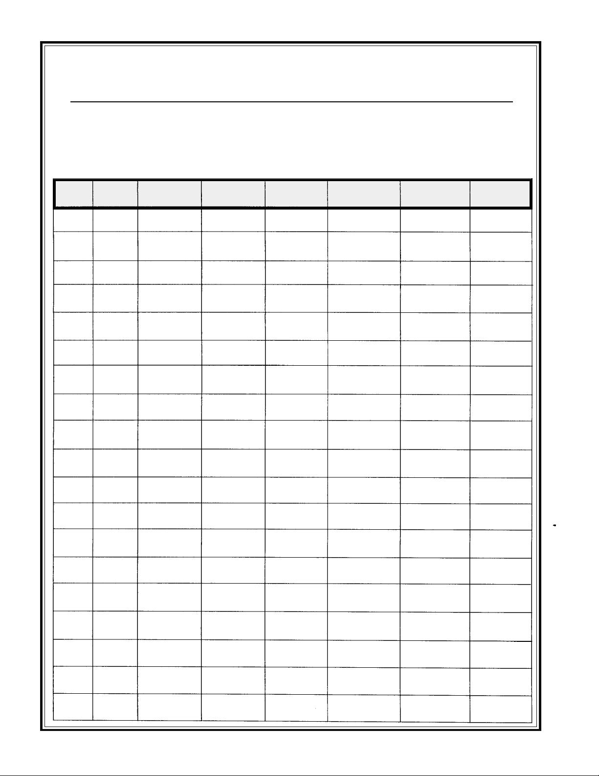
Model No. ______________________________________ Serial No. ___________________________________
SEE ENGINE MANUAL FOR FREQUENCY AND PART NUMBERS.
Date Engine Engine Fuel Air Spark Transmission
Oil Oil Filter Filter Filter Plugs Fluid
Service Record
- 22 -
Page 23

CALIFORNIA PROPOSITION 65 WARNING: Sawing and engine exhaust from this product contains
chemicals known to the State of California to cause
cancer, birth defects, or other reproductive harm.
Page 24
Bred Tough. T echnology Born to Work.
The W ay It Ought To Be.
Stone Construction Equipment, Inc.
P.O. Box 150, Honeoye, New York 14471
Phone: 1-800-888-9926
Fax: 1-585-229-2363
e-mail: [email protected]
www: stone-equip.com
A 100% employee-owned American manufacturer
© 1997 Stone Construction Equipment, Inc.
Printed in U.S.A.
GPC 1/98
 Loading...