

Page 1
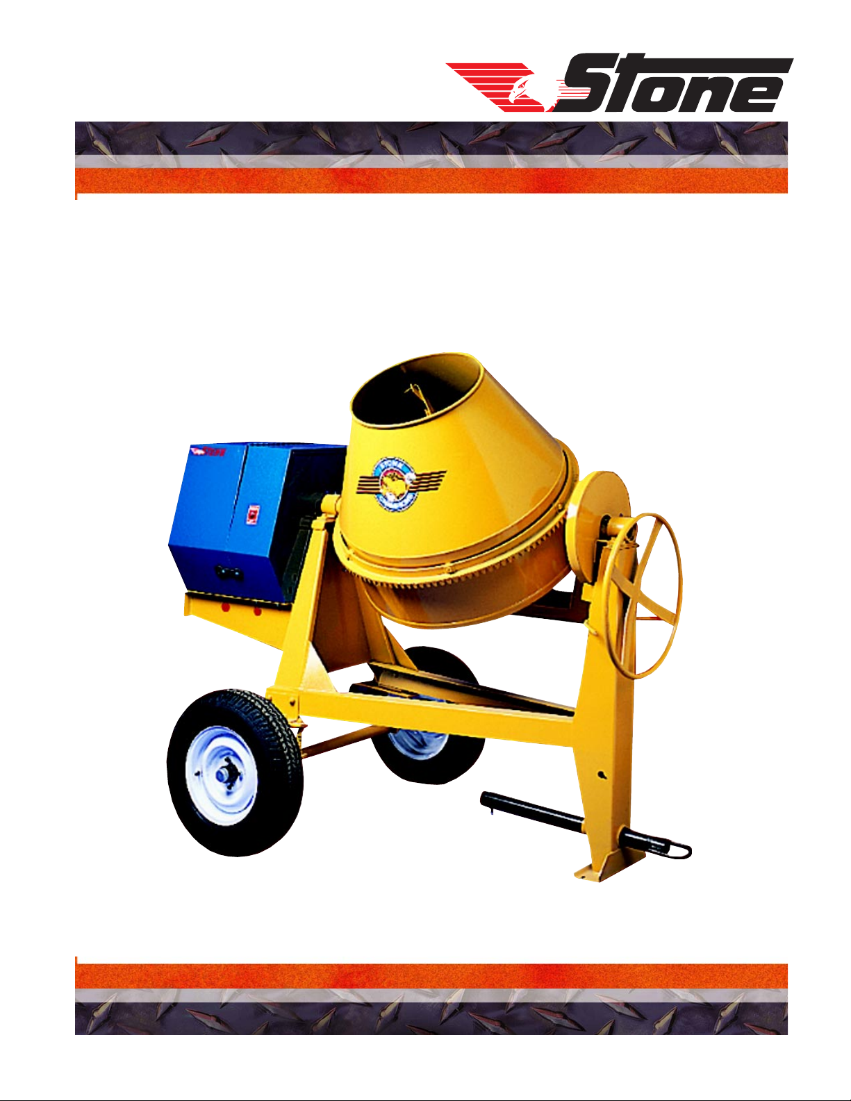
OPERATOR MANUAL
MODELS: 65CM, 75CM, 95CM, 105CM
CONCRETE MIXER
REVISION: B 2/2002 P/N 56394
Page 2

Technical Data
Stone 65CM, 75CM, 95CM, 105CM Mixer – Specifications
Specifications
Model Operating
Wt.
65CM
75CM
95CM
690 lbs.
(w/8hp
Honda)
313 kg
696 lbs.
(w/8hp
Honda)
315.7 kg
800 lbs.
(w/8hp
Honda)
362.9 kg
Batch
Capacity
(bags)
1/2 - 1
bag
3/4 - 1 1/4
bags
1 - 1 1/2
bags
Batch
Capacity
6 cu. ft.
.17 cu. m.
7 cu. ft.
.20 cu. m.
9 cu. ft.
.255 cu. m.
Total
Volume
9.0 cu. ft.
.255 cu. m.
9.5 cu. ft.
.27 cu. m.
15.1 cu. ft.
.43 cu. m.
L x W x H Power Source
78 x 46 x 58 (in)
198.1 x 116.8 x 147.3 (cm)
78 x 46 x 58 (in)
198.1 x 116.8 x 147.3 (cm)
84 x 56 x 65 (in)
213.4 x 142.2 x 165.1 (cm)
1 hp / .75 kW Elec tr ic
5 hp / 3.7 kW B&S
5.5 hp / 4.1 kW Honda
6 hp / 4.5 kW Robi n
6 hp / 4.5 kW Diesel
8.5 hp / 6.3 kW Rob i n
8 hp / 6 kW B&S K o ol Bo r e
8 hp / 5.9 kW B&S I/P
8 hp / 6 kW Honda
10 hp / 7.5 kW B& S I /P
1 hp / .75 kW Elec tr ic
5 hp / 3.7 kW B&S
5.5 hp / 4.1 kW Honda
6 hp / 4.5 kW Robi n
6 hp / 4.5 kW Diesel
8.5 hp / 6.3 kW Rob i n
8 hp / 6 kW B&S K o ol Bo r e
8 hp / 5.9 kW B&S I/P
8 hp / 6 kW Honda
10 hp / 7.5 kW B& S I /P
1 1/2 hp / 1.1 kW Ele ctric
6 hp / 4.5 kW Diesel
8.5 hp / 6.3 kW Rob i n
8 hp / 6 kW B&S K o ol Bo r e
8 hp / 5.9 kW B&S I/P
8 hp / 6 kW Honda
10 hp / 7.5 kW B& S I /P
105CM
821 lbs.
(w/8hp
Honda)
372.4 kg
1 1/4 - 1 3/4
bags
10 cu. ft.
.28 cu. m.
15.6 cu. ft.
.44 cu. m.
- 6 -
85 x 56 x 65 (in)
215.9 x 142.2 x 165.1 (cm)
1 hp / 1.1 kW Electric
6 hp / 4.5 kW Diesel
8.5 hp / 6.3 kW Rob i n
8 hp / 6 kW B&S K o ol Bo r e
8 hp / 5.9 kW B&S I/P
8 hp / 6 kW Honda
10 hp / 7.5 kW B& S I /P
Page 3
Technical Data
Imperial Torque Chart
SAE GRADE 5
Coarse Thread, Zinc-Plated
SIZE TORQUE SIZE TORQUE
ft. lbs. Nm ft. lbs. Nm
1/4 - 20 (.250) 681/4 - 20 (.250) 912
5/16 - 18 (.3125) 13 18 5/16 - 18 (.3125) 18 24
3/8 - 16 (.375) 23 31 3/8 - 16 (.375) 33 45
7/16 - 14 (.4375) 37 50 7/16 - 14 (.4375) 52 70
1/2 - 13 (.500) 57 77 1/2 - 13 (.500) 80 108
9/16 - 12 (.5625) 82 111 9/16 - 12 (.5625) 115 156
5/8 - 11 (.625) 112 152 5/8 - 11 (.625) 159 215
3/4 - 10 (.750) 200 271 3/4 - 10 (.750) 282 382
7/8 - 9 (.875) 322 436.5 7/8 - 9 (.875) 454 615
1 - 8 (1.000) 483 655 1 - 8 (1.000) 682 925
Coarse Thread, Zinc-Plated
SAE GRADE 5
Fine Thread, Zinc-Plated
SIZE TORQUE SIZE TORQUE
ft. lbs. Nm ft. lbs. Nm
1/4 - 28 (.250) 7101/4 - 28 (.250) 10 14
5/16 - 24 (.3125) 14 19 5/16 - 24 (.3125) 20 27
3/8 - 24 (.375) 26 35 3/8 - 24 (.375) 37 50
7/16 - 20 (.4375) 41 56 7/16 - 20 (.4375) 58 79
1/2 - 20 (.500) 64 87 1/2 - 20 (.500) 90 122
9/16 - 18 (.5625) 91 123 9/16 - 18 (.5625) 129 175
5/8 - 18 (.625) 128 173 5/8 - 18 (.625) 180 244
3/4 - 16 (.750) 223 302 3/4 - 16 (.750) 315 427
7/8 - 14 (.875) 355 481 7/8 - 9 (.875) 501 679
1 - 12 (1.000) 529 717 1 - 12 (1.000) 746 1011
1 -14 (1.000) 541 733 1 -14 (1.000) 764 1036
SAE GRADE 8
SAE GRADE 8
Fine Thread, Zinc-Plated
t-chrt_i.doc
- 7 -
Page 4

Technical Data
Property Class 8.8
ZINC-PLATED
SIZE Nm ft. lbs. Nm ft. lbs.
M6 9.9 7 NA NA
M8 24 18 25 18
M10 48 35 49 36
M12 83 61 88 65
M14 132 97 140 103
M16 200 148 210 155
M20 390 288 425 313
M24 675 498 720 531
Property Class 10.9
ZINC-PLATED
SIZE Nm ft. lbs. Nm ft. lbs.
M6 14 10 NA NA
M8 34 25 35 26
M10 67 49 68 50
M12 117 86 125 92
M14 185 136 192 142
M16 285 210 295 218
M20 550 406 600 443
M24 950 701 1000 738
Metric Torque Chart
Coarse Th read Fine Thread
Coarse Th read Fine Thread
Property Class 12.9
ZINC-PLATED
SIZE Nm ft. lbs. Nm ft. lbs.
M6 16.5 12 NA N A
M8 40 30 42 31
M10 81 60 82 60
M12 140 103 150 111
M14 220 162 235 173
M16 340 251 350 258
M20 660 487 720 531
M24 1140 841 1200 885
Conversion Factor: 1 ft. lb. = 1.3558 Nm
Coarse Th read Fine Thread
- 8 -
Page 5
Health & Safety
Safety Precautions
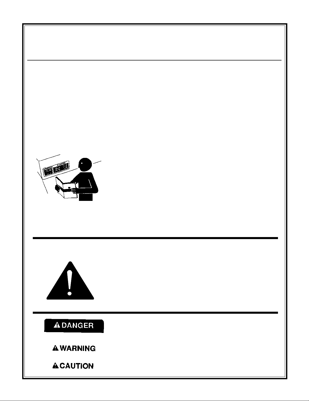
Before using this equipment, study this entire manual
to become familiar with its operation. Do not allow
untrained or unauthorized personnel, especially
children, to operate this equipment. Use only factory
authorized parts for service.
FOLLOW SAFETY INSTRUCTIONS
Carefully read all safety messages and decals in this manual and on
your machine safety signs. Keep decals in good condition. Replace
missing or damaged decals. Be sure new equipment components and
repair parts include the current safety signs. Replacement safety signs
and decals are available through your dealer.
Learn how to operate the machine and how to use controls properly.
Do not let anyone operate without instruction.
Keep your machine in proper working condition. Unauthorized
modifications to the machine may impair the function and/or safety
and affect machine life.
When warning decals are destroyed or missing, contact
the Manufacturer immediately at 1-800-888-9926 for
replacement. For the safety of yourself and others, it is
imperative that the following rules are observed. Failure
to do so may result in serious injury or death.
If you do not understand any part of this manual and need assistance,
contact your dealer.
This notation appears before warnings in the text. It means that the
step which follows must be carried out to avoid the possibility of
personal injury or death. These warnings are intended to help the
technician avoid any potential hazards encountered in the normal
service procedures. We strongly recommend that the reader takes
advantage of the information provided to prevent personal injury or
injury to others.
UNDERSTAND SIGNAL WORDS
A signal word DANGER, WARNING, or CAUTION is used with
the safety-alert symbol. DANGER identifies the most serious hazards.
DANGER or WARNING safety signs are located near specific
hazards. General precautions are listed on CAUTION safety signs.
CAUTION also calls attention to safety messages in this manual.
- 9 -
Page 6
Health & Safety
Safety Precautions
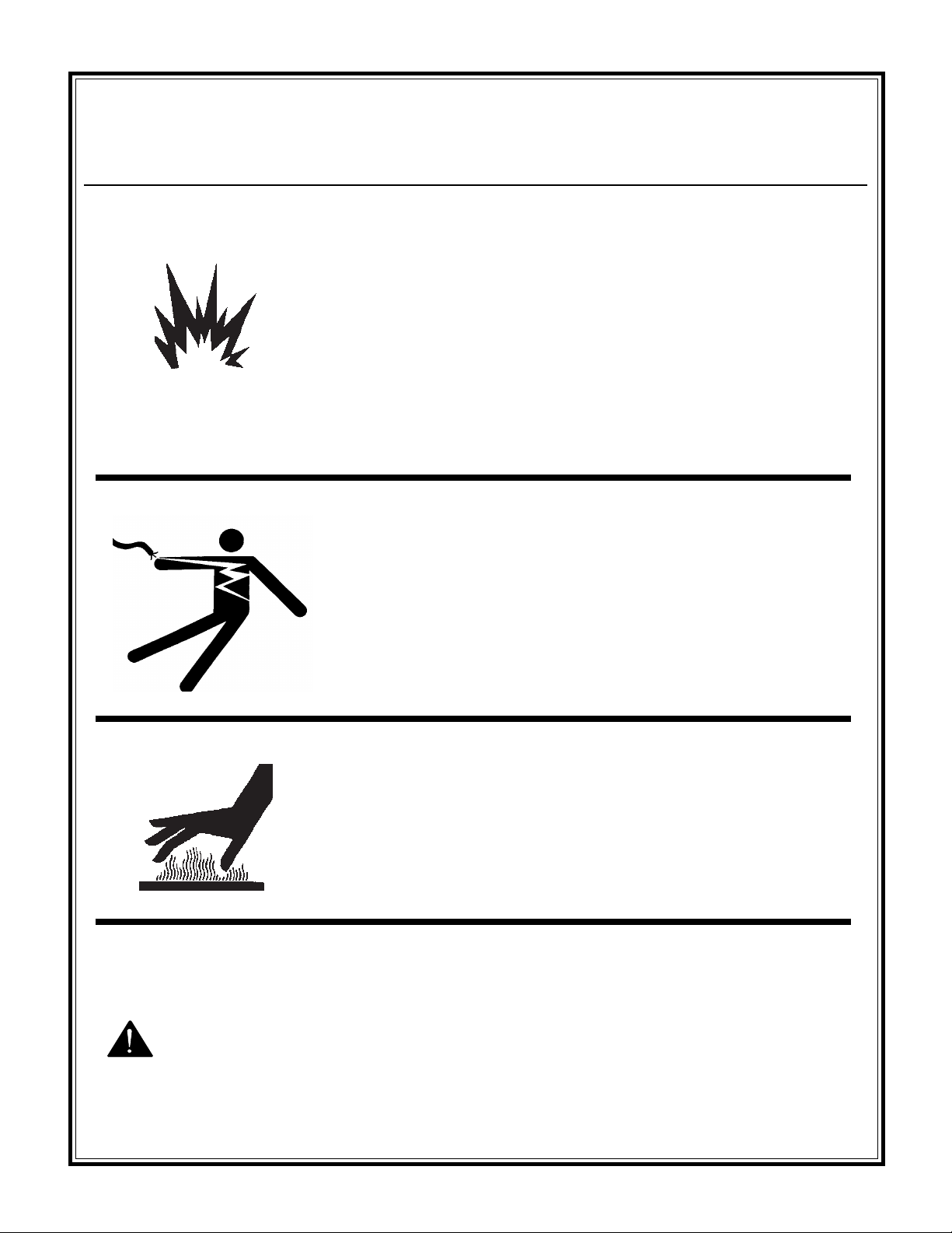
USE COMMON SENSE WHEN HANDLING FUELS
Transport and handle fuel only when contained in approved safety
container.
Do not smoke when refueling or during any other fuel handling
operation.
Do not refuel while the engine is running or while it is still hot.
If fuel is spilled during refueling, wipe it off of the engine
immediately and discard the rag in a safe place.
Do not operate the equipment if fuel or oil leaks exist - repair
immediately.
Never operate this equipment in an explosive atmosphere.
Always use the proper size grounded extension cord, conforming to
the National Electric Code and Local Ordinances.
Inspect all extensions and electrical cords for cuts, frayed wire and
broken connectors before use. Do not use cords if not in good
condition.
Do not route extension cords through standing water.
Do not operate the mixer in standing water.
When cleaning the mixer, never spray water on the electric motor.
WARNING
HOT SURFACES
Avoid contact with hot exhaust systems and engines.
Allow all components in the engine compartment to cool before
performing any service work.
Never leave mixer unattended while running.
Mix only concrete.
- 10 -
Page 7
Health & Safety
Safety Precautions
Never perform any work on the mixer while it is running.
Before working on the mixer, stop the engine and disconnect the
spark plug wire(s) to prevent accidental starting. On electric models,
disconnect the electric cord at the mixer.
Keep cowl closed and latched during the operation, close and latch
cowl immediately after starting.
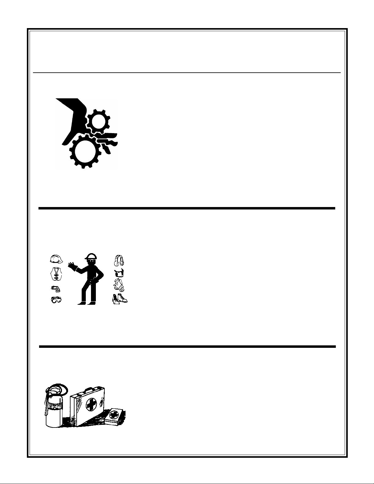
Keep hands, clothing and jewelry away from all moving parts.
Keep all guards in place, including drum guards.
Never place your hands or any solid object into the drum while the
mixer is in operation.
WEAR PROTECTIVE CLOTHING
Wear close fitting clothing and safety equipment appropriate to the
job.
Prolonged exposure to loud noise can cause impairment or loss of
hearing.
Wear a suitable hearing protective device such as earmuffs or
earplugs to protect against objectionable or uncomfortable loud
noises.
Operating equipment safely requires the full attention of the
operator. Do not wear radio or music headphones while operating
machine.
PREPARE FOR EMERGENCIES
Be prepared if a fire starts.
Keep a first aid kit and fire extinguisher handy.
Keep emergency numbers for doctors, ambulance service, hospital,
and fire department near your telephone.
- 11 -
Page 8
Health & Safety
Safety Precautions
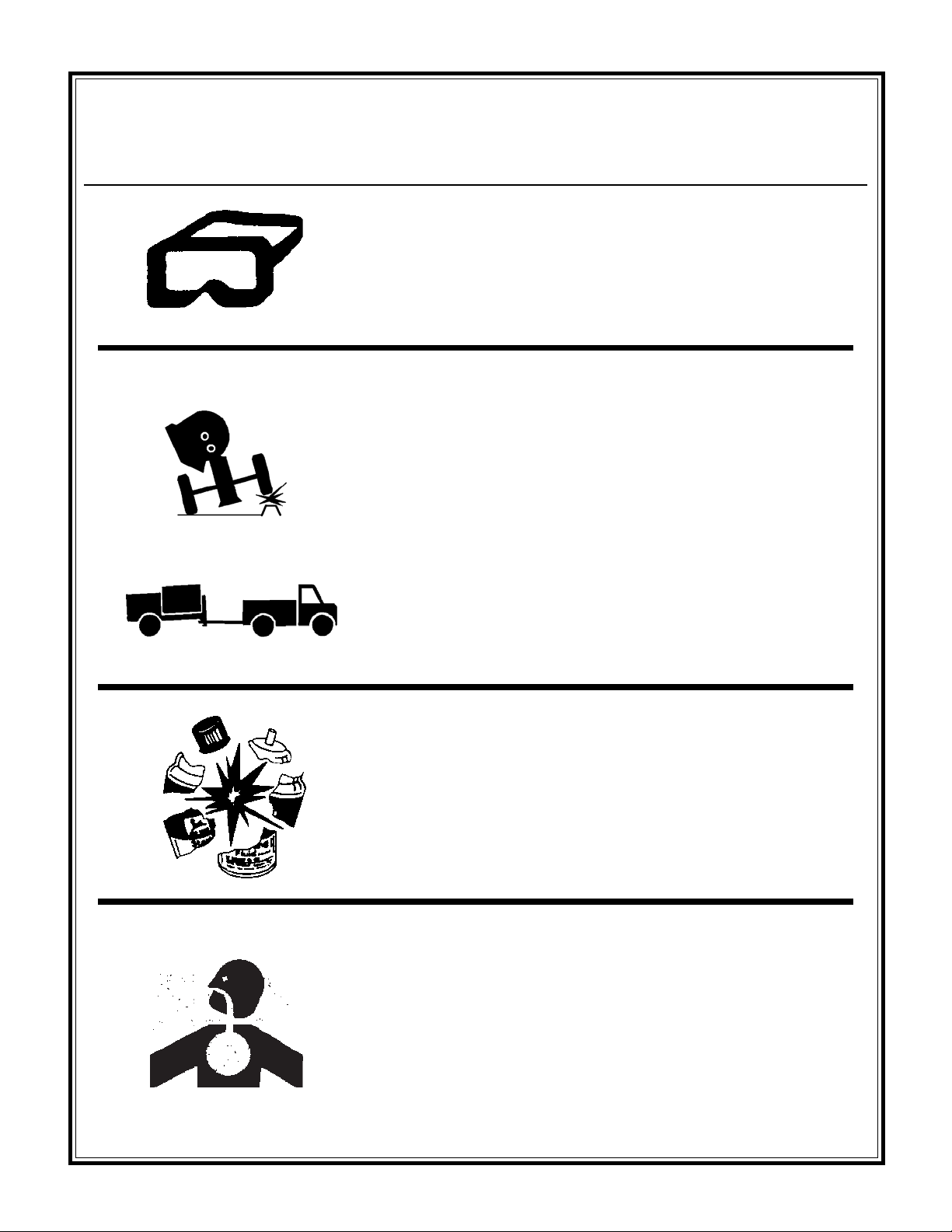
Warning-Eye Protection
• Always wear splash goggles when operating mixer.
Warning-Towing
• Warning: Do not tow the mixer with the drum in the dump position.
Mixer may become unstable and tip over when hitting a curb,
pothole, or other obstruction.
• Warning: Always properly attach safety chains before mixer is
towed. Maximum towing speed 55 m.p.h. (90 km/hr). Reduce
speed according to highway conditions.
Starting fluid (ether) is highly flammable, do not use or an
explosion or fire may result.
Never operate unit in a poorly ventilated or enclosed area.
Avoid prolonged breathing of exhaust gases.
Engine exhaust fumes can cause sickness or death.
- 12 -
Page 9

Health & Safety
Safety Precautions
PRACTICE SAFE MAINTENANCE
Understand service procedure before doing work. Keep area clean
and dry.
Never lubricate, service or adjust machine while it is moving. Keep
hands, feet, and clothing from power-driven parts. Disengage all
power and operate controls to relieve pressure. Lower equipment to
the ground. Stop the engine. Remove the key. Allow machine to
cool.
Securely support any machine elements that must be raised for
service work.
Keep all parts in good condition and properly installed. Repair
damage immediately. Replace worn or broken parts. Remove any
buildup of grease, oil, or debris.
Disconnect battery ground cable (-) before making adjustments on
electrical systems or welding on machine.
DISPOSE OF WASTE PROPERLY
Improperly disposing of waste can threaten the environment and
ecology. Potentially harmful waste used with equipment include
such items as oil, fuel, coolant, brake fluid, filters, and batteries.
Use leakproof containers when draining fluids. Do not use food or
beverage containers that may mislead someone into drinking from
them.
Do not pour waste onto the ground, down a drain, or into any water
source.
Air conditioning refrigerants escaping into the air can damage the
Earths atmosphere. Government regulations may require a certified
air conditioning service center to recover and recycle used air
conditioning refrigerants.
Inquire on the proper way to recycle or dispose of waste from your
local environmental or recycling center.
SAFETY DECALS - FOR THE SAFETY OF YOURSELF AND OTHERS REPLACE ANY
DAMAGED OR MISSING SAFETY DECALS.
Warning Decal (SN-92) P/N 55011
Safety Instruction Decal (SN-67A) P/N 55046
Warning Decal (SN-8) P/N 55127
Safety Chain Decal (Front Post, SN-66) P/N 55121
- 13 -
Page 10
Operation
BEFORE STARTING
Before Starting/Safety Chain/Oil
Levels and Lubrication/To Start 0
Mixers are shipped completely assembled and ready
for operation except for installation of the safety chain.
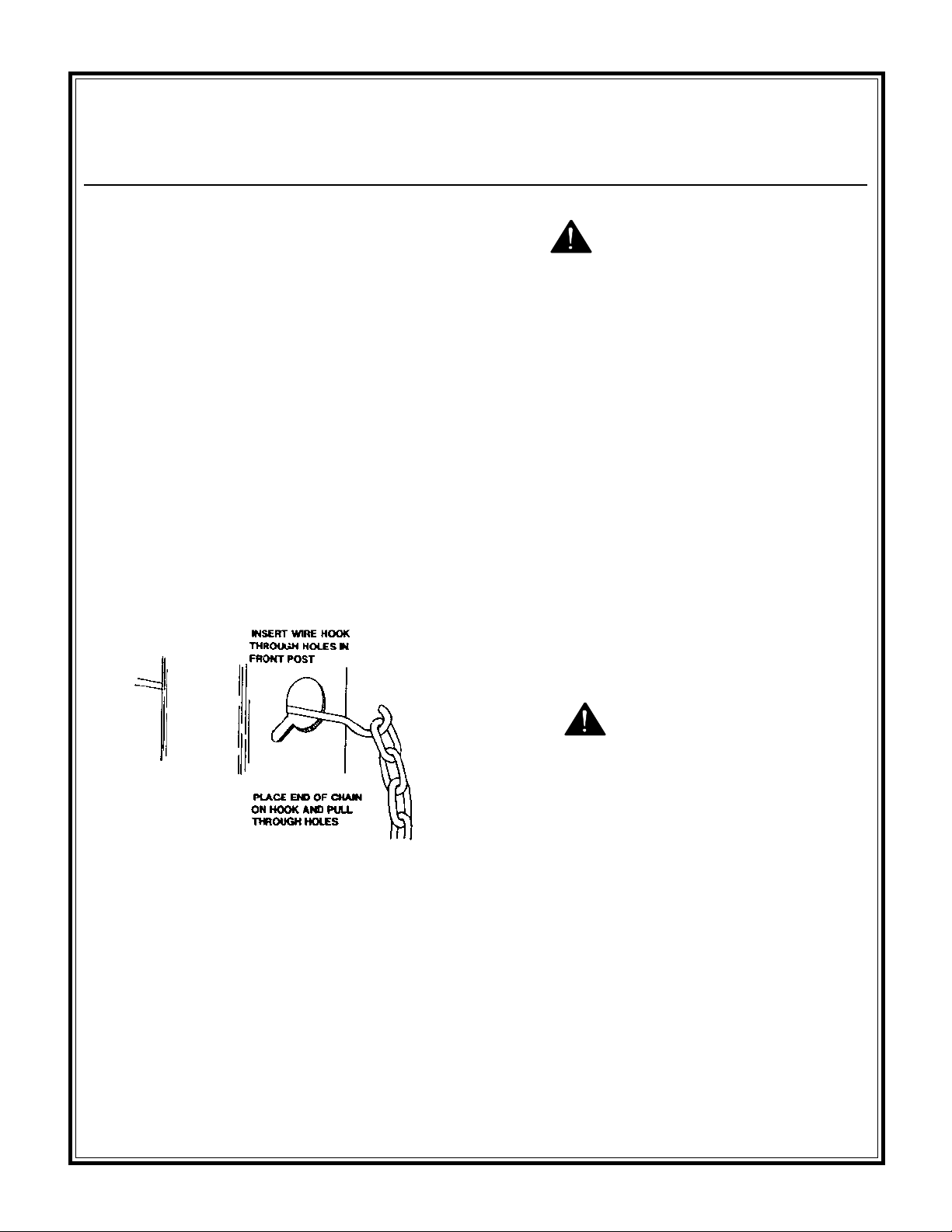
SAFETY CHAIN INSTALLATION
Remove the safety chain kit from the engine
compartment. The kit includes (1) 12 ft. length of
safety chain and (2) connecting links. Pull one end of
the chain through the (2) key hole slots located in the
front post of the mixer with a hook (see drawing below
and decal on mixer front post). Attach the connecting
links to each end of the chain. Follow the instructions
in the TOWING section of this manual and on the
mixer front post to attach the safety chain to the towing
vehicle.
INSTALLING CHAIN TO MIXER
WARNING
BEFORE WORKING ON MACHINE, MAKE
SURE ENGINE SPARK PLUG WIRE IS
DISCONNECTED, OR IF ELECTRIC, THAT THE
ELECTRIC CORD IS DISCONNECTED, TO
PREVENT ANY ACCIDENTAL STARTING.
HARDWARE
Check all hardware on mixer and engine / motor before
starting. Consult the TORQUE CHART section of this
manual and tighten any loose hardware accordingly.
FUEL
If your mixer is equipped with a gasoline engine, fill
the gas tank with clean gasoline from a safety can.
Consult the ENGINE MANUAL supplied with this unit
for the proper type of gasoline required.
DO NOT mix oil with gasoline.
OIL LEVELS AND LUBRICATION
Be sure to check the oil levels in the engine and engine
reduction unit BEFORE starting this unit. The engine
warranty is VOID if it is run without oil. Consult the
ENGINE MANUAL supplied with this unit for specific
instructions and oil recommendations.
Also check the trunnion bearings to make sure they
have been greased.
WARNING
FOLLOW THE GUIDELINES FOUND IN THE
SAFETY PRECAUTION SECTION OF THIS
MANUAL WHENEVER HANDLING GASOLINE.
TO START THE ENGINE/MOTOR
GASOLINE ENGINE COLD START - Open the fuel
valve under the gas tank all the way. Open the throttle
approximately half way and apply the choke. Pull the
starter rope sharply until the engine starts. When the
engine starts, open the choke and adjust the throttle as
necessary to keep it running. Allow the engine to warm
up for a few minutes before placing it under the load.
If the engine doesn't start after (3) pulls, open choke
slightly to prevent flooding. Always operate the engine
at full throttle when under load.
- 14 -
Page 11
Gas Hot Start/Electric Motors/To
Operation
GASOLINE ENGINE HOT START - Open the valve
under the gas tank all the way if it has been shut off.
Open the throttle approximately half way. Do not
apply the choke. Pull the starter rope sharply until the
engine starts. When the engine starts, adjust the
throttle. Always operate the engine at full throttle
when under load. Adjust engine speed so drum is
turning between 20 - 25 RPM.
NOTE: These starting instructions are general
guidelines only. Since many engine options are
available on the manufacturer's CM mixers, consult the
ENGINE MANUAL included with this unit for specific
instructions.
ELECTRIC MOTORS - Use the proper size (3) wire
(grounded) extension cord, conforming to the National
Electric Code and Local Ordinances. DO NOT use (2)
wire extension cord. Check any extension cord
carefully for broken connectors, bare wires, and
damaged insulation. DO NOT use any cord found to be
in poor condition. Make sure the extension cord is not
routed through standing water and that all the
connections are tight. Use the shortest extension cord
possible. Turn motor on.
TO STOP THE ENGINE / MOTOR
Start and S top/Operation
OPERATION
Start the engine / motor as previously instructed and
allow gasoline engines to reach operating temperatures.
Close the engine cowl. NEVER operate the mixer with
cowl open.
With drum operating between 20 - 25 RPM's the mixer
is now ready for the addition of the concrete mix. For
best results proceed as follows:
1. Pour the required amount of water into
drum.
2. Add the required amount of gravel.
3. Add the required amount of cement.
4. Add the required amount of sand. By
adding the water and gravel first the
drum will be kept clean and a good
tumbling action will be maintained when
cement and sand will be added.
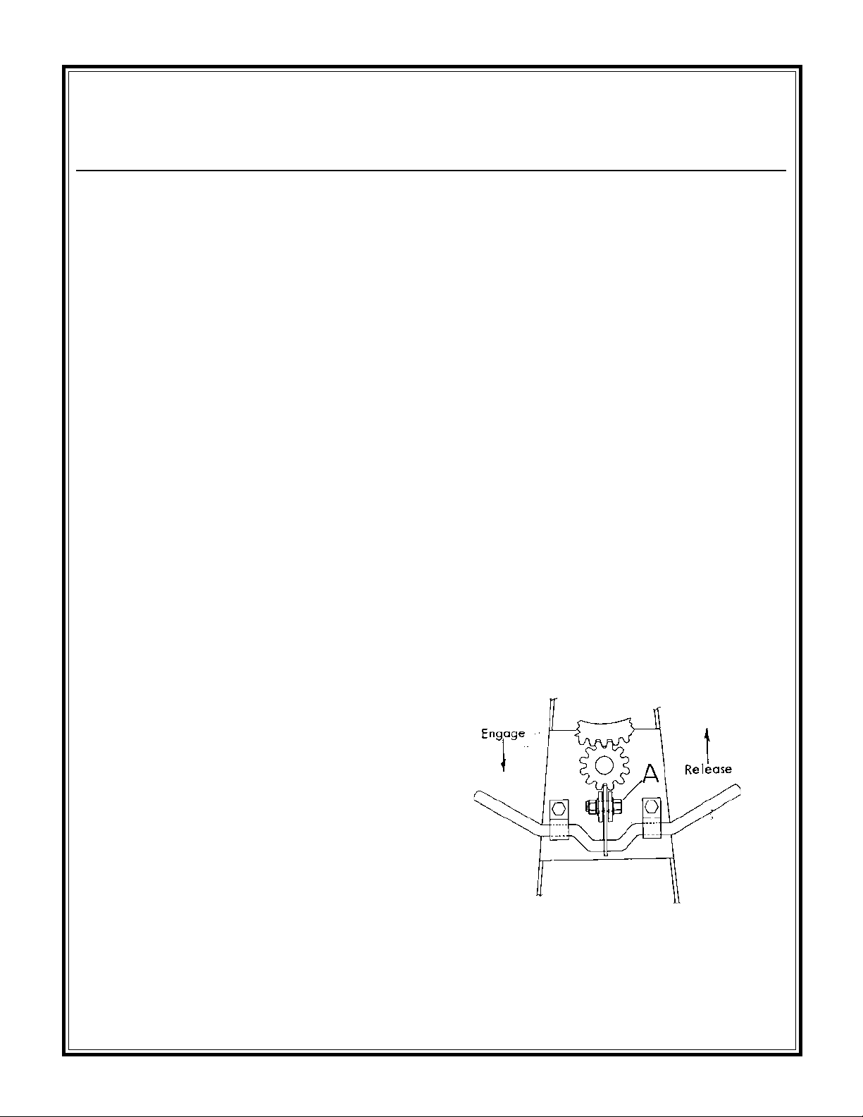
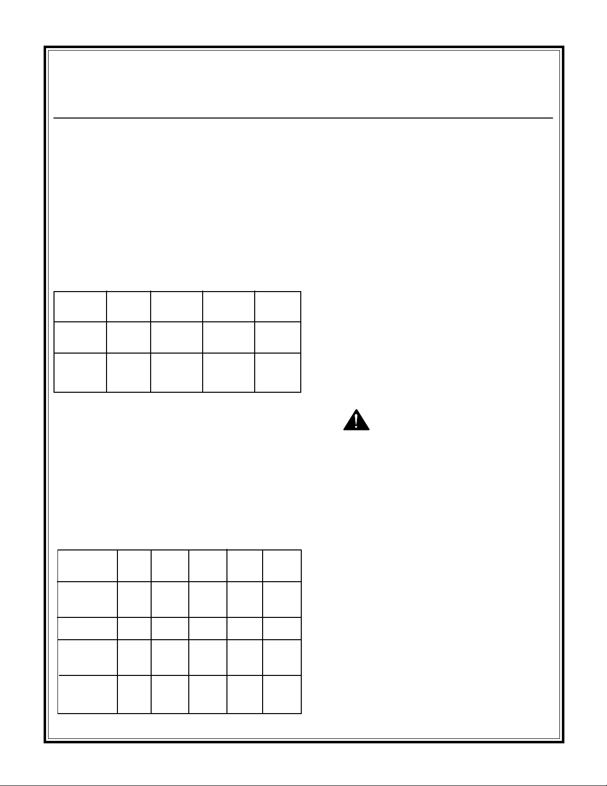
To discharge concrete, grasp handwheel firmly with
one hand and release tilt brake by pushing up on the tilt
handle with the other. See diagram below.
GASOLINE ENGINES - Depress grounding switch
located on stationary cowl half and hold down until
engine stops completely. Consult the ENGINE
MANUAL included with this unit for specific
instructions. If the mixer is to be left unattended for
any length of time, close the fuel valve under the gas
tank.
ELECTRIC MOTORS - Turn the motor off. If the
mixer is to be left unattended for any length of time,
disconnect the power cord.
To prevent accidental discharge, never release brake
without holding the handwheel firmly. Do not attempt
to grab the handwheel to stop an accidental discharge,
serious injury could result. Always make sure that the
brake is fully engaged after discharge of concrete and
before reloading the drum.
- 15 -
Page 12
Operation
Capacities/Sample Mix/Cleaning
After discharge of concrete, immediately pour in the
required amount of water for the next batch.
NOTE: When servicing brake mechanism, bolt A
should be tightened so that approximately 17 - 18
pounds of force is required to release the brake. This
will prevent accidental discharge due to vibration.
CAPACITIES
65CM 75CM 95CM 105CM
Total Drum 9.0 cu. ft. 9.5 cu. ft. 15.1 cu. ft. 15.6 cu. ft.
Volume
Max Batch 6.0 cu. ft. 7.0 cu. ft. 9.0 cu. ft. 10.0 cu. ft.
Size*
* Maximum batch size depends on mix and type of
aggregate used.
CLEANING
For consistent performance, long life and continued
high quality mixing of cement, thoroughly clean the
mixer inside and out at the end of each day's operation.
Drum may be scoured by 2 minute operation with
gravel and water mixture. Discharge, then hose down
drum inside and outside. Keep mixer clean.
Before cleaning, shut off the engine or motor and
disconnect the spark plug wire or electric cord to
prevent accidental starting. Spray the mixer with
water before the mix dries to remove any
accumulations. Dried mix should be scraped out as
necessary. DO NOT beat on drum with shovel,
hammer or other device to break up accumulations of
dried mix, as this will dent and damage the drum.
WARNING
SAMPLE MIX
Volume relationship of 1:2-1/4:3
(cement : sand : gravel) mix. The mix volume may
vary depending on aggregate used.
Mix Volume
Cu. Ft. 346 9 10
Cement
(bags) 1/2 2/3 1 1-1/2 1-3/4
Water (gal.) 2-1/2 3-1/2 5-1/4 8 9-1/4
Sand (gal./
shovels) 912182730
Gravel (gal./
shovels) 12 16 23 36 40
NEVER POUR OR SPRAY WATER ON THE
ENGINE OR MOTOR.
NEVER PUT HANDS OR ANY OBJECT INTO
THE DRUM WHILE THE ENGINE OR MOTOR
IS RUNNING.
ALWAYS DISCONNECT THE SPARK PLUG
WIRE OR ELECTRIC CORD WHEN CLEANING
INSIDE DRUM.
- 16 -
Page 13
Operation
TOWING
Before attempting to tow this mixer, check the state
and local laws that apply to your intended route and
check the following:
1. Hitch attached to the towing vehicle
securely.
2. Tow pole fully extended and bolted to mixer
securely.
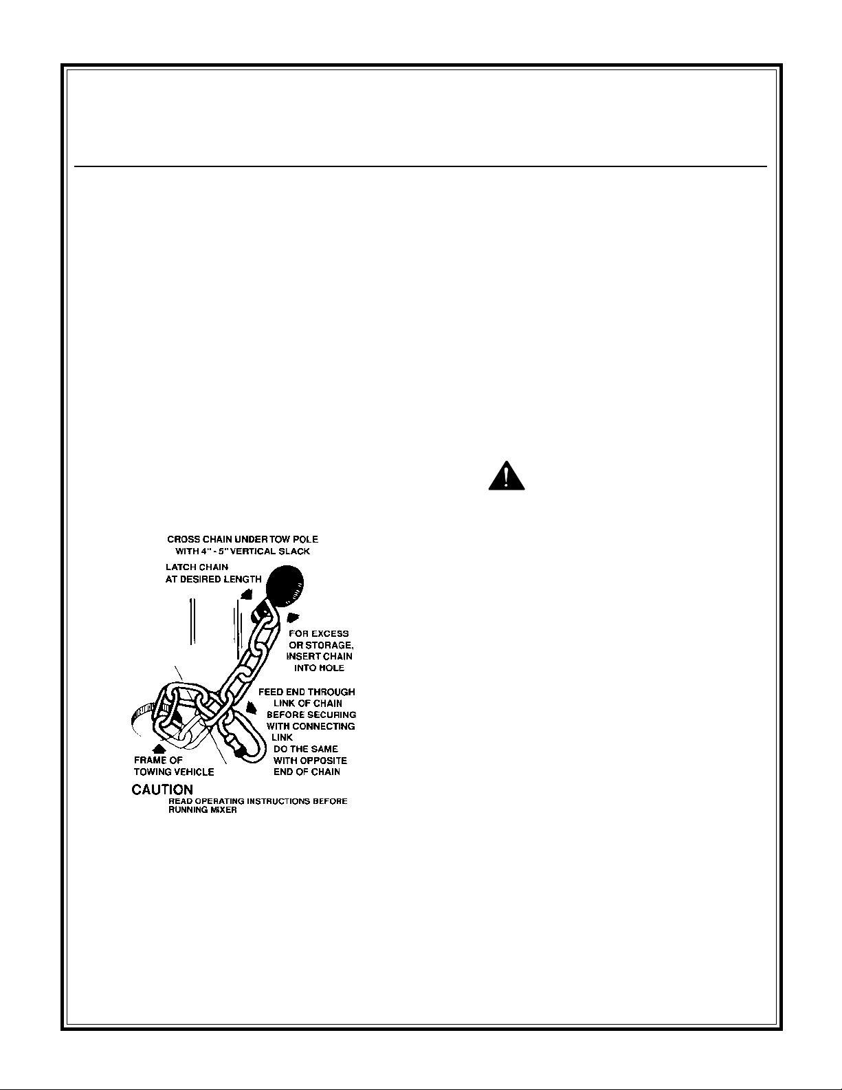
3. Safety chain hooked up properly (see
illustration or decal on mixer front post).
INSTALLING CHAIN TO VEHICLE
Towing/Attaching Chain to Vehicle
6. Tires in good shape and at proper inflation
as follows:
Tire size 4.80 x 12 @ 60 P.S.I. (65CM & 75CM)
Tire size 6.50 x 13 @ 35 P.S.I. (95CM & 105CM)
Refer to FRAME AND DRUM ASSEMBLY and
AXLE ASSEMBLY section of the Service/Parts
Manual for parts identification and location.
WARNING
DO NOT EXCEED A TOWING SPEED OF 55
MILES/HR (90 KM/HR). FOR POOR ROAD
CONDITIONS OR INCLEMENT WEATHER,
REDUCE SPEED ACCORDINGLY.
4. Lug nuts, wheel nuts and axle mount nuts tight.
5. Drum rotated straight down, tilt brake in
engaged (down) position to lock drum in place.
- 17 -
Page 14
Maintenance
NOTE: Cowl removed for clarity. Do not operate
mixer with cowl removed.
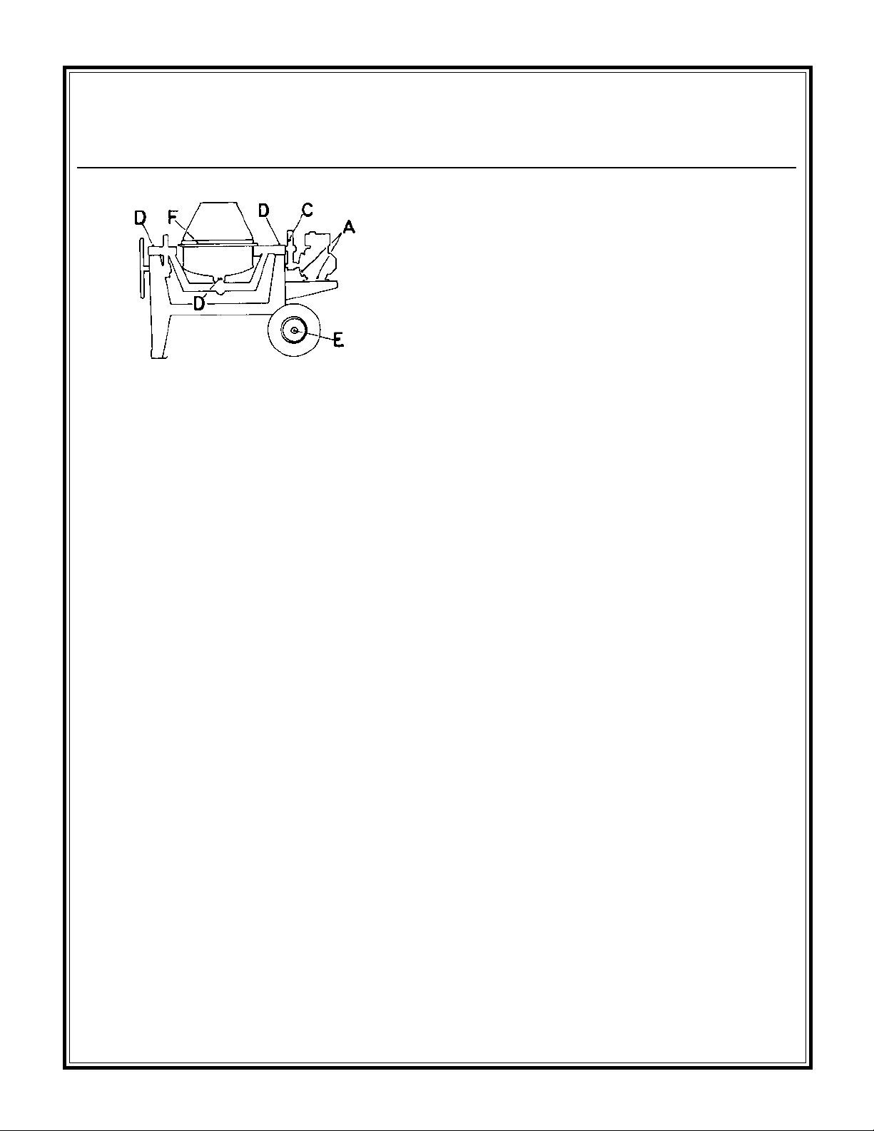
A. ENGINE - Daily check the oil levels in the
engine and engine reduction unit. The engine
warranty is VOID if run without oil. Since there
are many options available on this mixer, consult
the ENGINE MANUAL for specific recommendations as to oil level, oil type required and
frequency of oil changes required. For maximum
service life from the engine, follow those recommendations.
Schedule
E. YEARLY - Repack (4) tapered roller bearings in wheel hubs and replace wheel seals.
Install washer and nut. Torque to 20 ft. lbs.
back off one turn, torque to 7 ft. lbs. back off to
first slot in nut and insert cotter key.
F. DO NOT lubricate pinion and ring gear.
They will collect abrasive materials and accelerate wear.
Lubricate diesel gearbox with SAE30W oil as
needed.
Use any Grade #1 lithium base grease for the
above applications.
* See Exploded Views with Parts Section of this
manual for exact location.
* Gearbox gasket kit P/N 23197.
B. * WEEKLY - Grease idler shaft pillow block
bearings on electric drive models.
*WEEKLY - Check diesel gearbox oil level.
Oil level should be visible at pipe plug. Lubricate
diesel gearbox with SAE30W to SAE80W oil as
needed.
C. WEEKLY - Lubricate chain and sprockets on
chain drive models with a few drips of SAE 30
motor oil or any spray chain lube.
D. MONTHLY - Grease trunnions (2) places
and drum spindle (2) places.
- 18 -
 Loading...