

Page 1
OPERATOR & SERVICE MANUAL
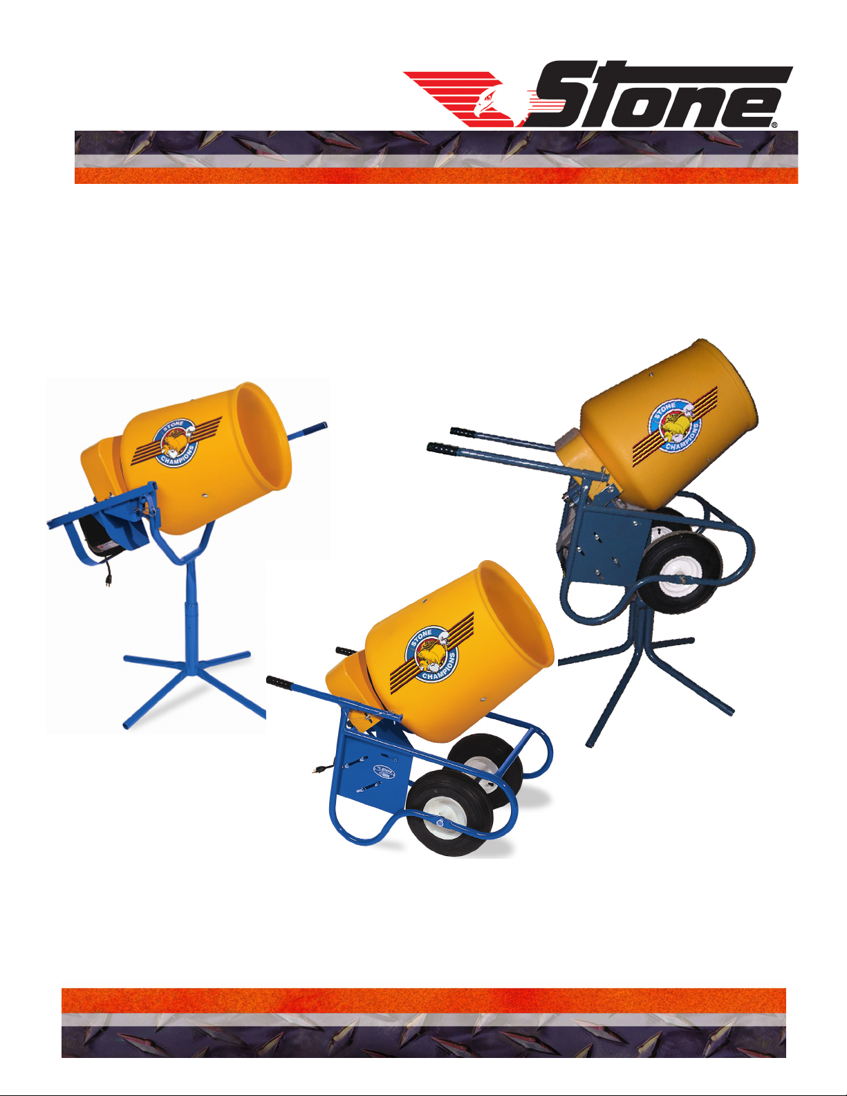
MODEL: 25CMP Wheelbarrow, 25CMPT Pedestal &
25CMPC Combination
CHAMPION
®
PLASTIC CONCRETE MIXER
A 100% employee-owned American manufacturer
REVISION: D 01/2005 PN 56517
Page 2

TECHNICAL DATA
25CMPT/25CMP/25CMPC Mixer – Specifications
25CMPT
(Pedestal)
Operating Weight
(lbs.)
113 123 123
25CMP
(Wheelbarrow)
Specifications
25CMPC
(Combination)
Batch Capacity
(bags)
Batch Capacity:
Total Volume of
empty drum
Capacity: Concrete
Volume Total (wet)
L x W x H
Motor H.P.
Motor RPM
Voltage
Frequency (Hz)
¼ bag ¼ bag ¼ bag
3.5 cu. ft. 3.5 cu. ft. 3.5 cu. ft.
2 cu. ft 2 cu. ft. 2 cu. ft.
---
1/3 Electric
6 amp
1725 1725 1725
115 115 115
60 60 60
1/3 Electric
6 amp
1/3 Electric
6 amp
Phase
Drum RPM
V-Belt (4L Section)
Length
Drum Diameter x
Opening
Drum Type
Structure
Portability
Single Single Single
31 31 31
25" 28" 28"
---
Polyethylene Drum Polyethylene Drum Polyethylene Drum
Pedestal Wheelbarrow Pedestal /
Wheelbarrow
Separates into 4-
pieces
- 6 -
Wheeled Frame Wheeled Frame
Separates into 4-
pieces
Page 3
TECHNICAL DATA
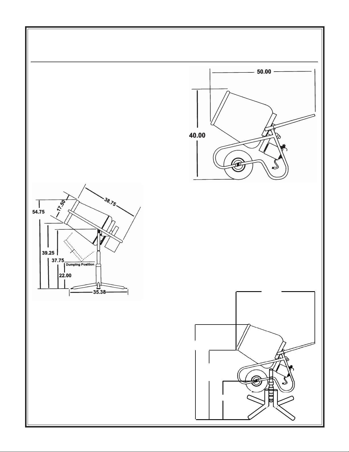
25CMP Wheelbarrow
Dimensions
Dimensions
25CMPT Pedestal
Dimensions
25CMPC Combination
Wheelbarrow/Pedestal
Dimensions
50.00
62.50
48.00
(27.50 Dump
Position)
25.50
- 7 -
Page 4
TECHNICAL DATA
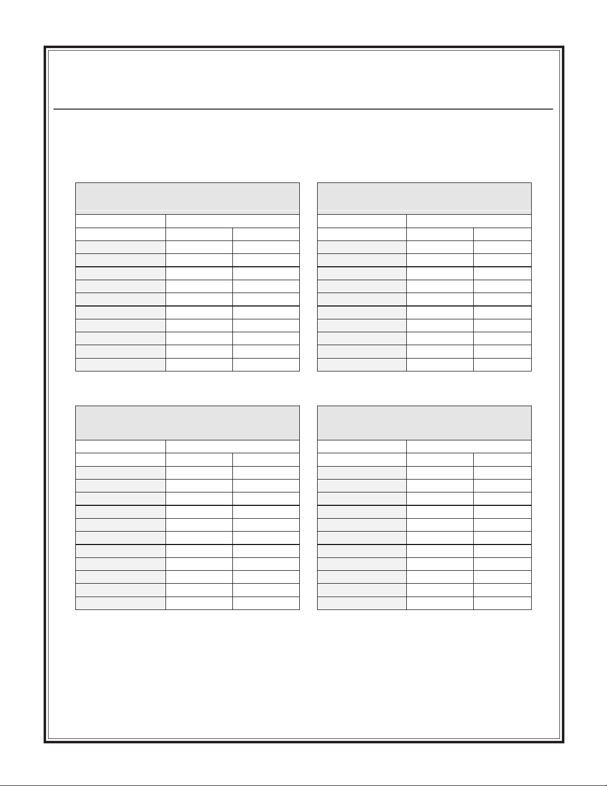
Imperial Torque Chart
SAE GRADE 5
Coarse Thread, Zinc-Plated
SIZE TORQUE SIZE TORQUE
ft. lbs. Nm ft. lbs. Nm
1/4 - 20 (.250) 681/4 - 20 (.250) 912
5/16 - 18 (.3125) 13 18 5/16 - 18 (.3125) 18 24
3/8 - 16 (.375) 23 31 3/8 - 16 (.375) 33 45
7/16 - 14 (.4375) 37 50 7/16 - 14 (.4375) 52 70
1/2 - 13 (.500) 57 77 1/2 - 13 (.500) 80 108
9/16 - 12 (.5625) 82 111 9/16 - 12 (.5625) 115 156
5/8 - 11 (.625) 112 152 5/8 - 11 (.625) 159 215
3/4 - 10 (.750) 200 271 3/4 - 10 (.750) 282 382
7/8 - 9 (.875) 322 436.5 7/8 - 9 (.875) 454 615
1 - 8 (1.000) 483 655 1 - 8 (1.000) 682 925
Coarse Thread, Zinc-Plated
SAE GRADE 5
Fine Thread, Zinc-Plated
SIZE TORQUE SIZE TORQUE
ft. lbs. Nm ft. lbs. Nm
1/4 - 28 (.250) 7101/4 - 28 (.250) 10 14
5/16 - 24 (.3125) 14 19 5/16 - 24 (.3125) 20 27
3/8 - 24 (.375) 26 35 3/8 - 24 (.375) 37 50
7/16 - 20 (.4375) 41 56 7/16 - 20 (.4375) 58 79
1/2 - 20 (.500) 64 87 1/2 - 20 (.500) 90 122
9/16 - 18 (.5625) 91 123 9/16 - 18 (.5625) 129 175
5/8 - 18 (.625) 128 173 5/8 - 18 (.625) 180 244
3/4 - 16 (.750) 223 302 3/4 - 16 (.750) 315 427
7/8 - 14 (.875) 355 481 7/8 - 9 (.875) 501 679
1 - 12 (1.000) 529 717 1 - 12 (1.000) 746 1011
1 -14 (1.000) 541 733 1 -14 (1.000) 764 1036
SAE GRADE 8
SAE GRADE 8
Fine Thread, Zinc-Plated
t-chrt_i.doc
- 8 -
Page 5
TECHNICAL DATA
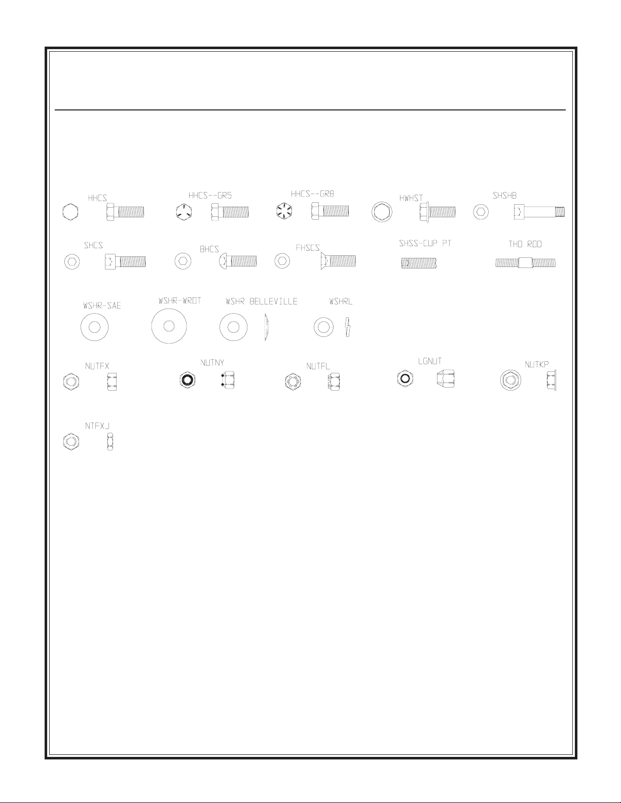
Hardware Identification
- 9 -
Page 6
HEALTH & SAFETY
Safety Precautions
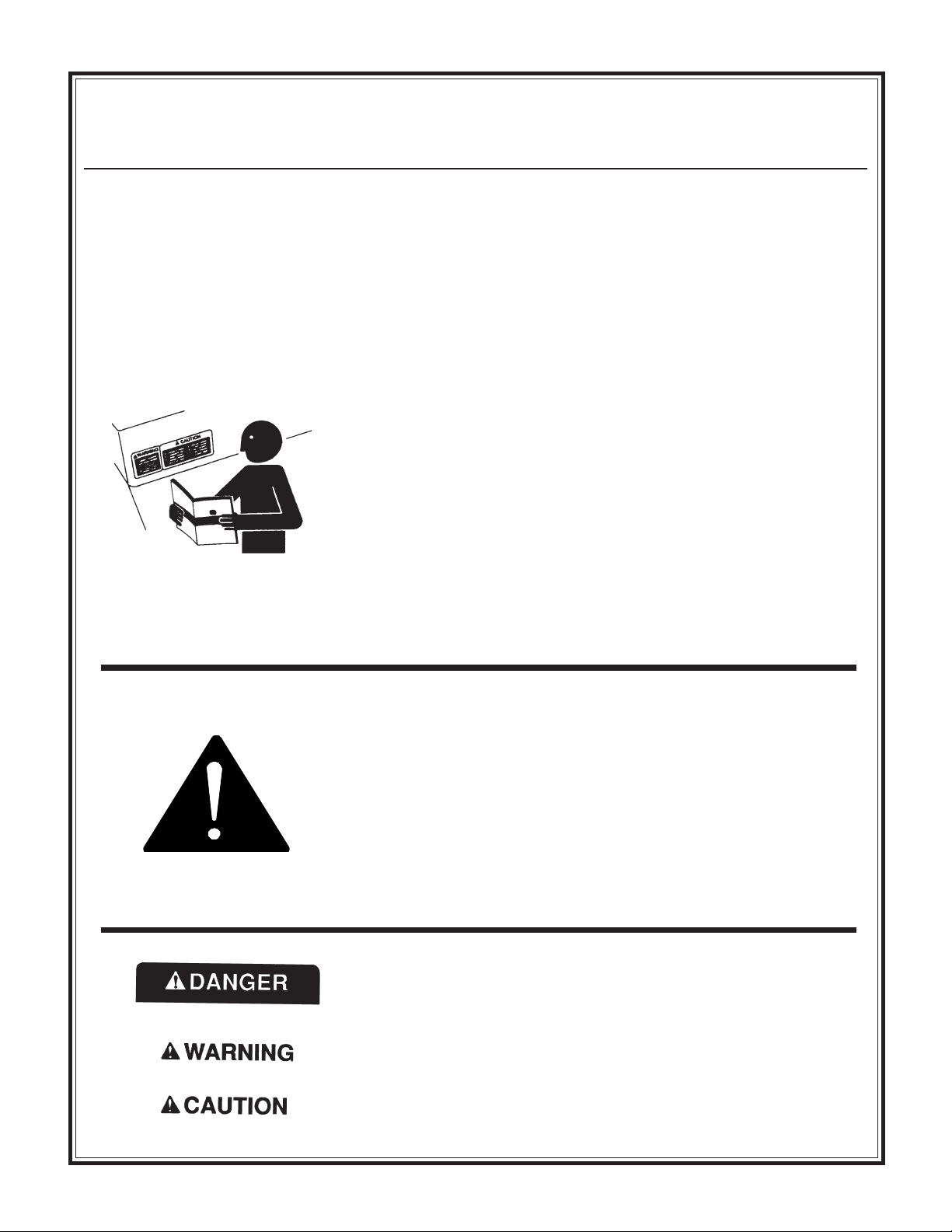
Before using this equipment, study this entire manual to
become familiar with its operation. Do not allow
untrained or unauthorized personnel, especially children,
to operate this equipment. Use only factory authorized
parts for service.
FOLLOW SAFETY INSTRUCTIONS
Carefully read all safety messages and decals in this manual and on
your machine safety signs. Keep decals in good condition. Replace
missing or damaged decals. Be sure new equipment components and
repair parts include the current safety signs. Replacement safety
signs and decals are available through your dealer.
Learn how to operate the machine and how to use controls properly.
Do not let anyone operate without instruction.
Keep your machine in proper working condition. Unauthorized
modifications to the machine may impair the function and/or safety
and affect machine life.
If you do not understand any part of this manual and need assistance,
contact your dealer.
When warning decals are destroyed or missing, contact
the Manufacturer immediately at 1-800-888-9926 for
replacement. For the safety of yourself and others, it is
imperative that the following rules are observed. Failure
to do so may result in serious injury or death.
This notation appears before warnings in the text. It means that the
step which follows must be carried out to avoid the possibility of
personal injury or death. These warnings are intended to help the
technician avoid any potential hazards encountered in the normal
service procedures. We strongly recommend that the reader takes
advantage of the information provided to prevent personal injury or
injury to others.
UNDERSTAND SIGNAL WORDS
A signal word DANGER, WARNING, or CAUTION is used with
the safety-alert symbol. DANGER identifies the most serious hazards.
DANGER or WARNING safety signs are located near specific
hazards. General precautions are listed on CAUTION safety signs.
CAUTION also calls attention to safety messages in this manual.
- 10 -
Page 7
HEALTH & SAFETY
USE COMMON SENSE WHEN HANDLING FUELS
Transport and handle fuel only when contained in approved safety
container.
Do not smoke when refueling or during any other fuel handling
operation.
Do not refuel while the engine is running or while it is still hot.
If fuel is spilled during refueling, wipe it off from the engine
immediately and discard the rag in a safe place.
Do not operate the equipment if fuel or oil leaks exist - repair
immediately.
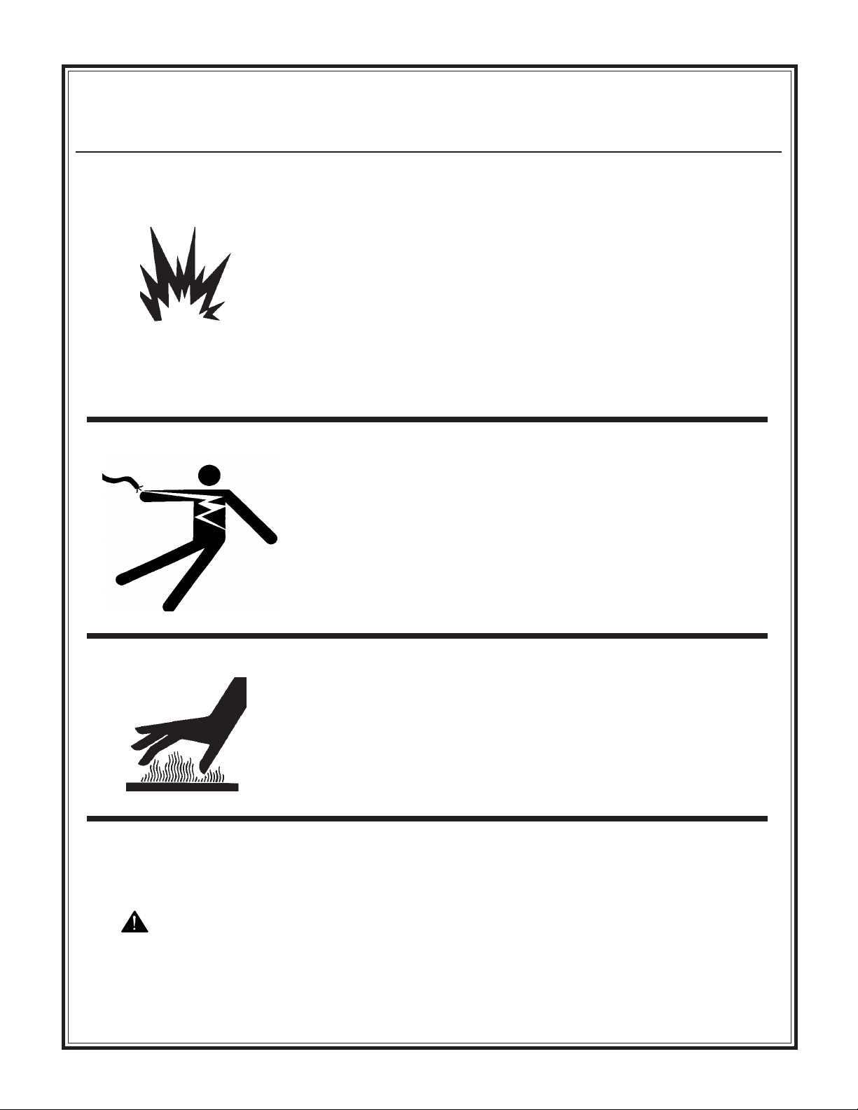
Never operate this equipment in an explosive atmosphere.
Always use the proper size grounded extension cord, conforming to
the National Electric Code and Local Ordinances.
Inspect all extensions and electrical cords for cuts, frayed wire and
broken connectors before use. Do not use cords if not in good
condition.
Do not route extension cords through standing water.
Do not operate the mixer in standing water.
When cleaning the mixer, never spray water on the electric motor.
Safety Precautions
WARNING
HOT SURFACES
Avoid contact with hot exhaust systems and engines.
Allow all components in the engine compartment to cool before
performing any service work.
Never leave mixer unattended while running.
Mix only concrete.
- 11 -
Page 8
HEALTH & SAFETY
Never perform any work on the mixer while it is running.
Before working on the mixer, stop the engine and disconnect the
spark plug wire(s) to prevent accidental starting. On electric models,
disconnect the electric cord at the mixer.
Keep cowl closed and latched during the operation, close and latch
cowl immediately after starting.
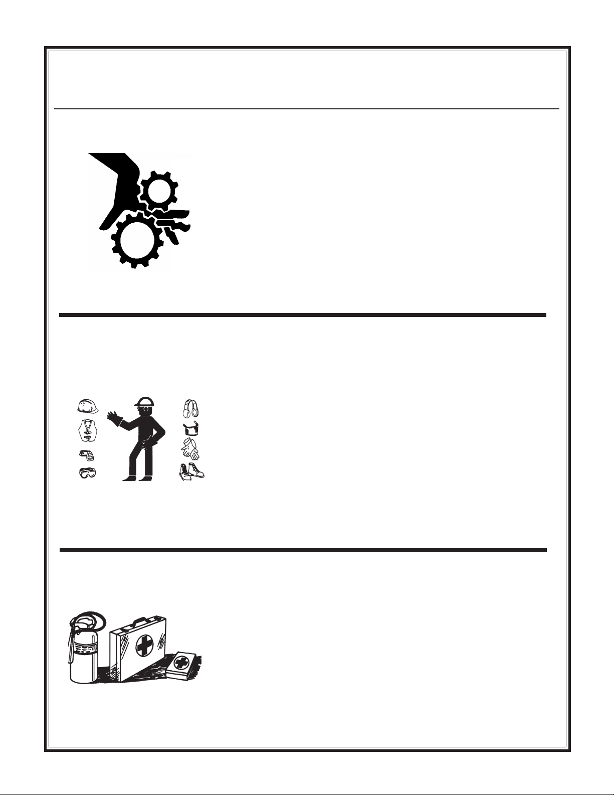
Keep hands, clothing and jewelry away from all moving parts.
Keep all guards in place, including drum guards.
Never place your hands or any solid object into the drum while the
mixer is in operation.
WEAR PROTECTIVE CLOTHING
Wear close fitting clothing and safety equipment appropriate to the
job.
Safety Precautions
Prolonged exposure to loud noise can cause impairment or loss of
hearing.
Wear a suitable hearing protective device such as earmuffs or
earplugs to protect against objectionable or uncomfortable loud
noises.
Operating equipment safely requires the full attention of the
operator. Do not wear radio or music headphones while operating
machine.
PREPARE FOR EMERGENCIES
Be prepared if a fire starts.
Keep a first aid kit and fire extinguisher handy.
Keep emergency numbers for doctors, ambulance service, hospital,
and fire department near your telephone.
- 12 -
Page 9
HEALTH & SAFETY
Warning-Eye Protection
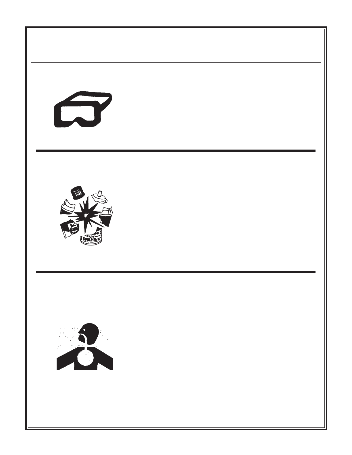
• Always wear splash goggles when operating mixer.
Starting fluid (ether) is highly flammable, do not use or an
explosion or fire may result.
Safety Precautions
Never operate unit in a poorly ventilated or enclosed area.
Avoid prolonged breathing of exhaust gases.
Engine exhaust fumes can cause sickness or death.
- 13 -
Page 10
HEALTH & SAFETY
PRACTICE SAFE MAINTENANCE
Understand service procedure before doing work. Keep area clean
and dry.
Never lubricate, service or adjust machine while it is moving. Keep
hands, feet, and clothing from power-driven parts. Disengage all
power and operate controls to relieve pressure. Lower equipment to
the ground. Stop the engine. Remove the key. Allow machine to
cool.
Securely support any machine elements that must be raised for
service work.
Keep all parts in good condition and properly installed. Repair
damage immediately. Replace worn or broken parts. Remove any
buildup of grease, oil, or debris.
Disconnect battery ground cable (-) before making adjustments on
electrical systems or welding on machine.
DISPOSE OF WASTE PROPERLY
Safety Precautions
Improperly disposing of waste can threaten the environment and
ecology. Potentially harmful waste used with equipment include
such items as oil, fuel, coolant, brake fluid, filters, and batteries.
Use leakproof containers when draining fluids. Do not use food or
beverage containers that may mislead someone into drinking from
them.
Do not pour waste onto the ground, down a drain, or into any water
source.
Air conditioning refrigerants escaping into the air can damage the
Earths atmosphere. Government regulations may require a certified
air conditioning service center to recover and recycle used air
conditioning refrigerants.
Inquire on the proper way to recycle or dispose of waste from your
local environmental or recycling center.
SAFETY DECALS - FOR THE SAFETY OF YOURSELF AND OTHERS REPLACE ANY
DAMAGED OR MISSING SAFETY DECALS.
Decal Safety Instructions (CMPT) PN 55046
Decal Safety Instructions (25CMP) PN 55491
Decal Instruction Mix (25CMP) PN 55490
Decal Grease PN 55492
Decal Warning PN 55493
- 14 -
Page 11

Before Starting/Hardware/Start
OPERATION
BEFORE STARTING
The 25CMP mixer is shipped completely assembled
and ready for operation.
WARNING
TO PREVENT ANY ACCIDENTAL
STARTING, MAKE SURE THE
ELECTRIC CORD IS
DISCONNECTED
HARDWARE
& Stop Electric Motor
TO STOP THE ELECTRIC MOTOR
Turn motor off.
Disconnect the power cord.
OPERATION
Start the motor as instructed.
With drum operating between 25-30 RPM, the mixer
is now ready for the addition of the concrete mix.
For best results proceed as follows:
1. Pour the required amount of water into
drum.
2. Add the required amount of gravel.
3. Add the required amount of cement.
Check all hardware on mixer before starting.
Consult the TORQUE CHART section of this
manual and tighten any loose hardware accordingly.
TT
O STO ST
ARAR
T T
T
O ST
TT
O STO ST
Use the proper size (3) wire (grounded)
extension cord, conforming to the National Electric Code and Local Ordinances. DO NOT use (2) wire extension
cords. Check any extension cord which
you plan on using carefully for broken
connectors, bare wires, or damaged
insulation. DO NOT use any cord found
to be in poor condition. Make sure the
extension cord is not routed through
standing water and that all connections
are tight. Use the shortest extension cord
possible.
Plug into any 115 single phase, 60-cycle,
fused outlet.
Turn motor on.
Check belt tension and tracking .
THE ELECTRIC MOTHE ELECTRIC MO
AR
T
THE ELECTRIC MO
ARAR
T T
THE ELECTRIC MOTHE ELECTRIC MO
TT
T
TT
OROR
OR
OROR
4. Add the required amount of sand.
By adding the water and gravel first the drum will be
kept clean and a good tumbling action will be
maintained when cement and sand are added.
Discharge the mixer and immediately pour in the
required water for the next batch.
Total Drum 3.5 cu. ft.
Volume
Max Batch 2 cu. ft.
Size*
CAPACITIES
* Maximum batch size depends on mix and type of
aggregate used.
- 15 -
Page 12

How to Mix /How to Mix Sand &
OPERATION
How to Mix Concrete
1. You will need approximately 2-1/2 gallons
of water
2. 2-80 lb. bags of pre-mix concrete
3. Start mixer in motion
4. Put in 2-gallons of water
5. Add 1-80 lb. bag of pre-mix concrete
Note: Mixture will be very sloppy
6. Slowly add second bag of concrete
7. Add ½ gallon of water slowly to obtain
desired thickness
How to Mix Sand and Gravel
Gravel/Maintenance & Lubrication
WARNING
NEVER POUR OR SPRAY WATER ON
THE MOTOR.
NEVER PLACE HANDS OR ANY
OBJECT INTO THE DRUM WHILE
THE MOTOR IS RUNNING.
ALWAYS DISCONNECT THE
ELECTRIC CORD WHEN CLEANING
INSIDE THE DRUM.
1. Use an 8-1/2 x 12-inch square point shovel
2. Portland cement, gravel or round stone and
masonry sand
3. Start mixer in motion
4. Put in 2 gallons of water
5. Add 6 shovels full of gravel or round stone
6. Add 2 shovels full of Portland Cement
7. Slowly add 4 shovels full masonry sand
Note: Water will vary according to moisture
content of sand and gravel
MAINTENANCE and LUBRICATION
To get long and trouble-free service from this mixer,
it is essential that you perform periodic maintenance.
Adjust belt as required by loosening the (4) motor
mount bolts and moving motor as necessary.
Retighten these bolts after adjustment. The belt
should deflect approximately 1/4 inch at the halfway
point when 5-10 lbs of pressure is applied.
Adjust pinion/gear mesh as required by loosening
the two (2) pinion jackshaft bolts and moving
jackshaft as necessary. Retighten these bolts after
adjustment.
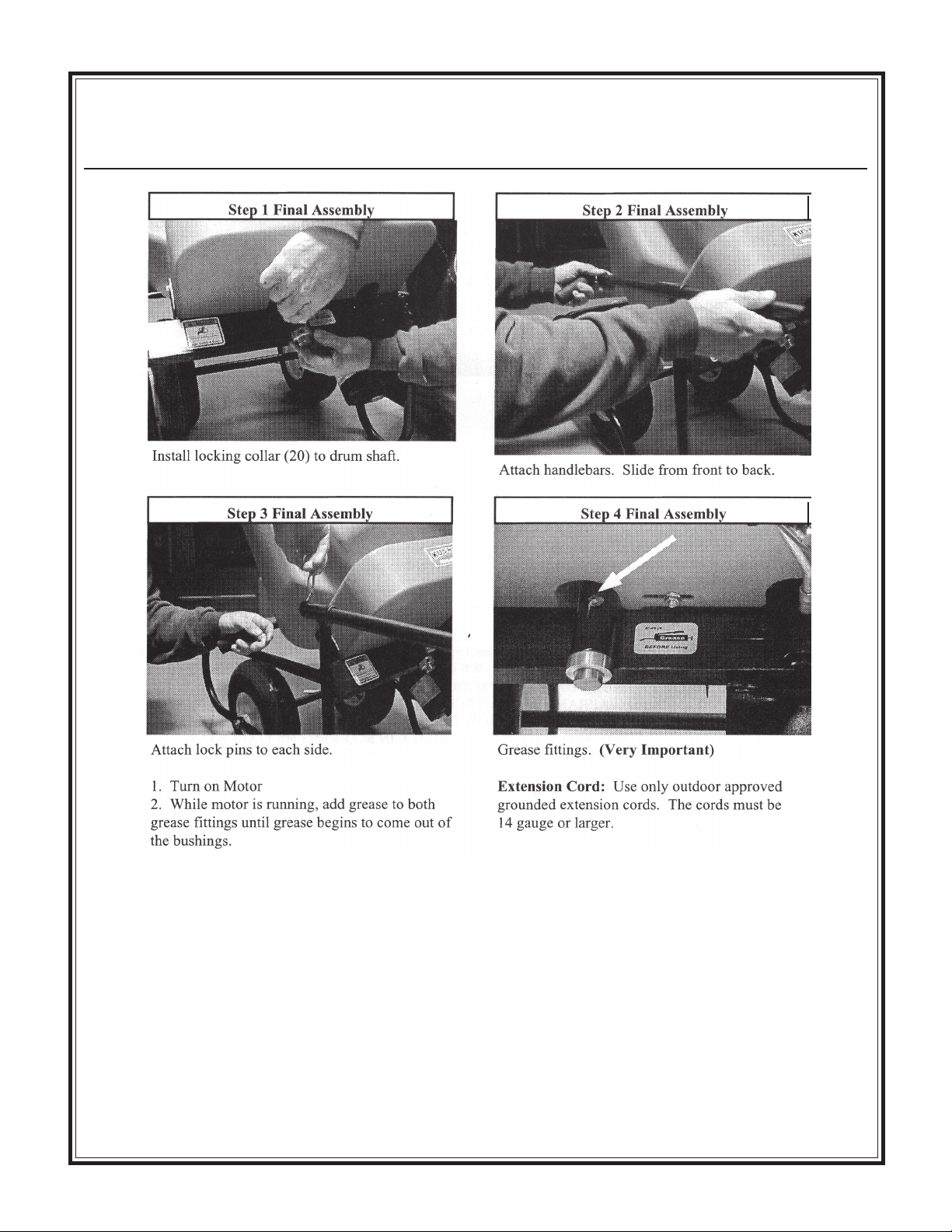
Grease after each use through the (2) fittings
provided. Use any Grade #1 lithium based grease.
DO NOT grease or oil the gear. This will attract
sand and cause excessive wear.
- 16 -
Page 13

Maintenance
PEDESTAL MODEL ASSEMBLY
WARNING
WHENEVER ASSEMBLING,
LUBRICATING OR ADJUSTING ANY
PART OF THE MIXER, DISCONNECT
THE POWER PLUG.
To attach motor (6) to frame assembly (4), line up
motor to match the four holes on the side motor
mount. Attach the V-belt (8) to the motor pulley (7).
Using the four 5/16 x ¾ in Hex Flange Screws (31)
and four 5/16 Hex Flange Lock Nuts (32), secure
the motor in place. The V-belt should be tightened
until the belt deflects approximately ¼ in when 5-10
pounds of force is applied centrally between the
pulleys. Assemble base legs (1 and 2). Assemble
Yoke (3) to assembled base and pin (29). Using two
people, lift and place Frame Assembly (4) onto Yoke
(3) pivot pins and insert pins (26). Slide dump
handle Grip (19) over the end of the Dump Handle
(18) and insert the Handle in the Frame Assembly
(4).
GREASE
25CMPT Pedestal Assembly
WARNING
KEEP HANDS AND CLOTHING
AWAY FROM MOVING JACKSHAFT
AND GEAR.
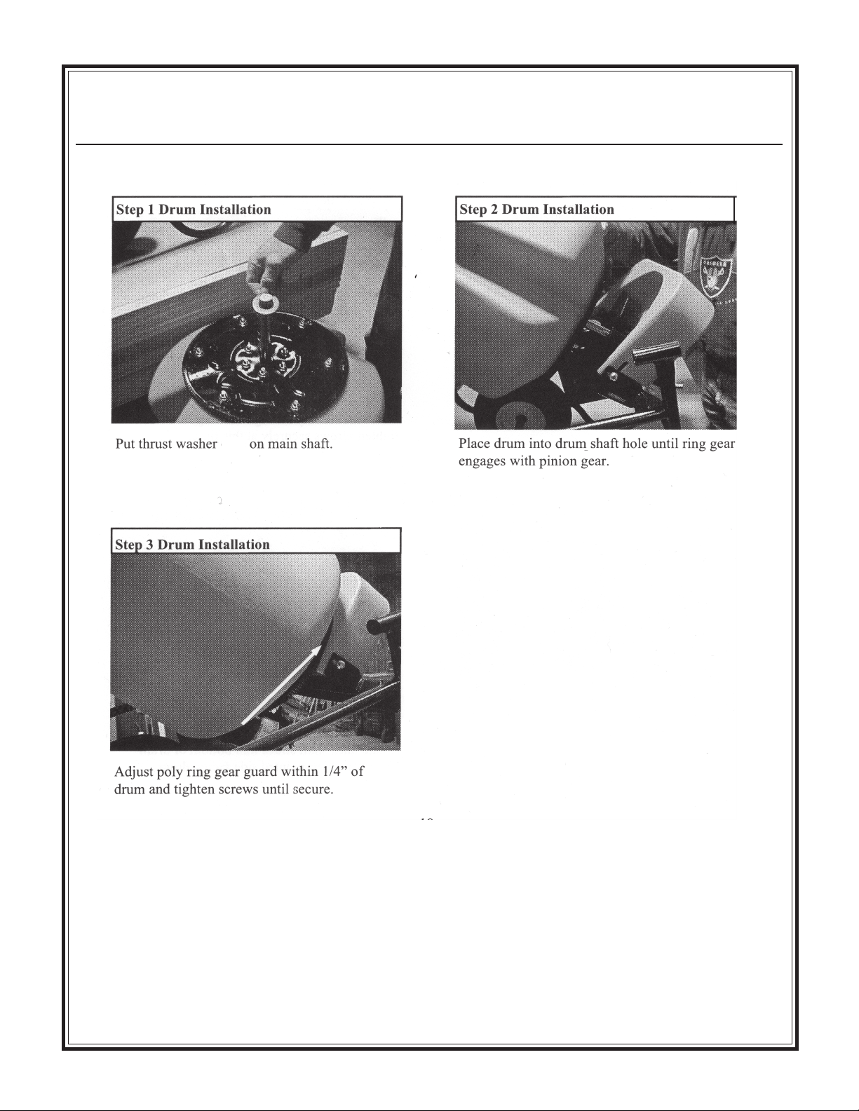
Place Thrust Washer (25) onto Drum Shaft (15) and
lightly grease the shaft. Using two people, carefully
slide the Drum assembly with shaft into the tube
located centrally on the Frame (4). Check to see that
the Jackshaft Gear (10) is properly meshing with the
Drum Main Gear (14). Place locking Collar (17)
onto Shaft (15) and tighten setscrew.
Grease the Fitting (24) on the Drum Shaft tube until
grease appears near the locking Collar (17) and the
Thrust Washer (30).
Check the clearance of Gear Guard (21) and the
Drum (5) to make sure there is no contact between
the rotating Drum and the Guard.
LUBRICATION
Any grease fittings (Item 24) require an application
of any type EP grease after each use. Apply grease
until grease begins to come out of the bushings.
Lubricate before each use of the mixer.
Using a grease gun, apply grease to the Fitting (24)
on the Jackshaft Tube if not already greased at
factory. Plug in the Power Cord. Let the motor run
for about 5 to 8 minutes, then turn off motor. This
will break-in the jackshaft bushings.
- 17 -
Page 14
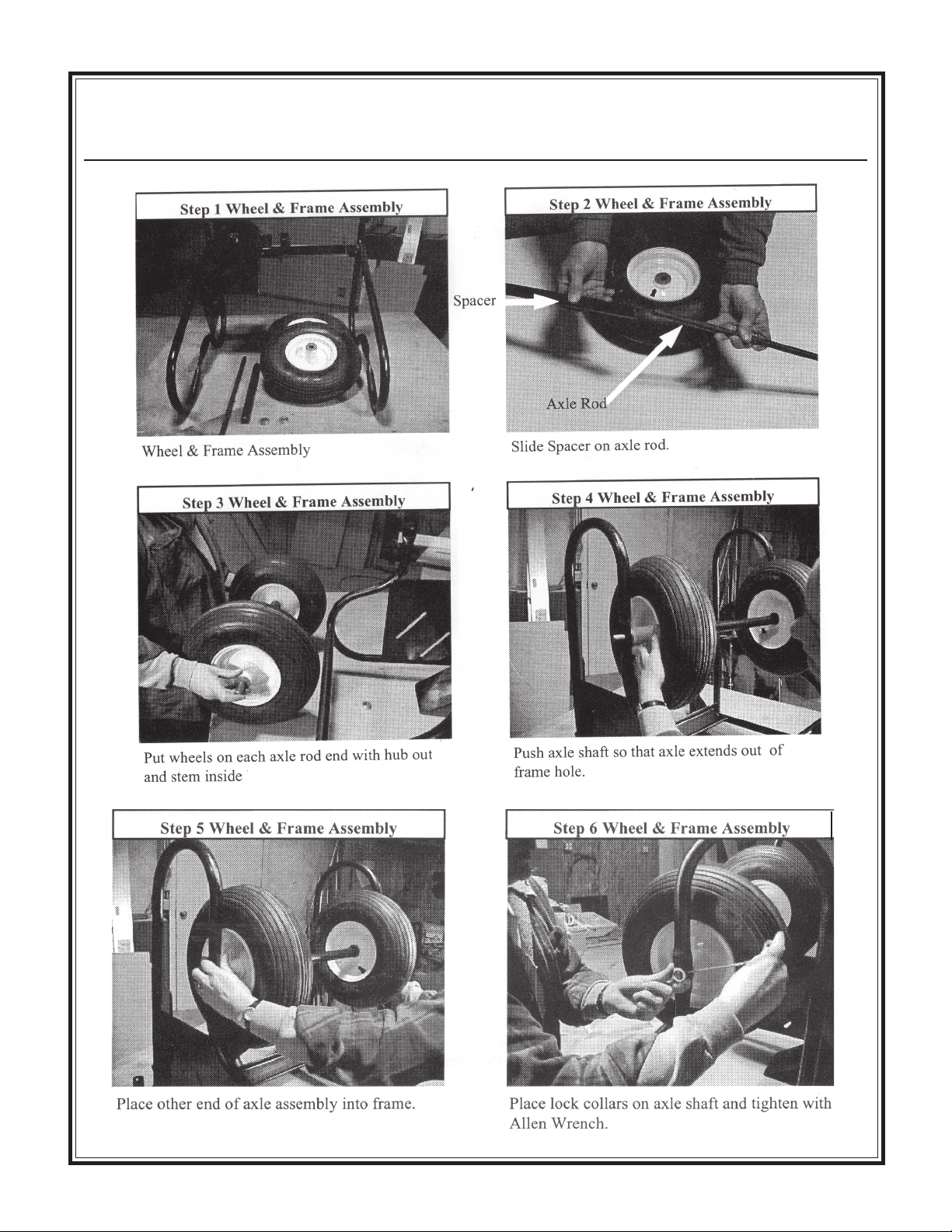
25CMP Wheelbarrow--
Maintenance
Wheel & Frame Assembly
- 18 -
Page 15
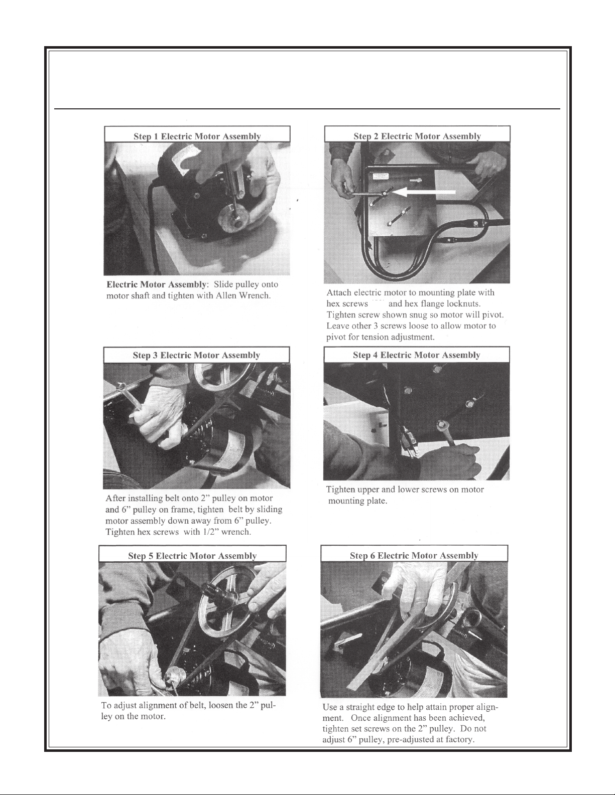
25CMP Wheelbarrow--
Maintenance
Electric Motor Assembly
35
- 19 -
Page 16
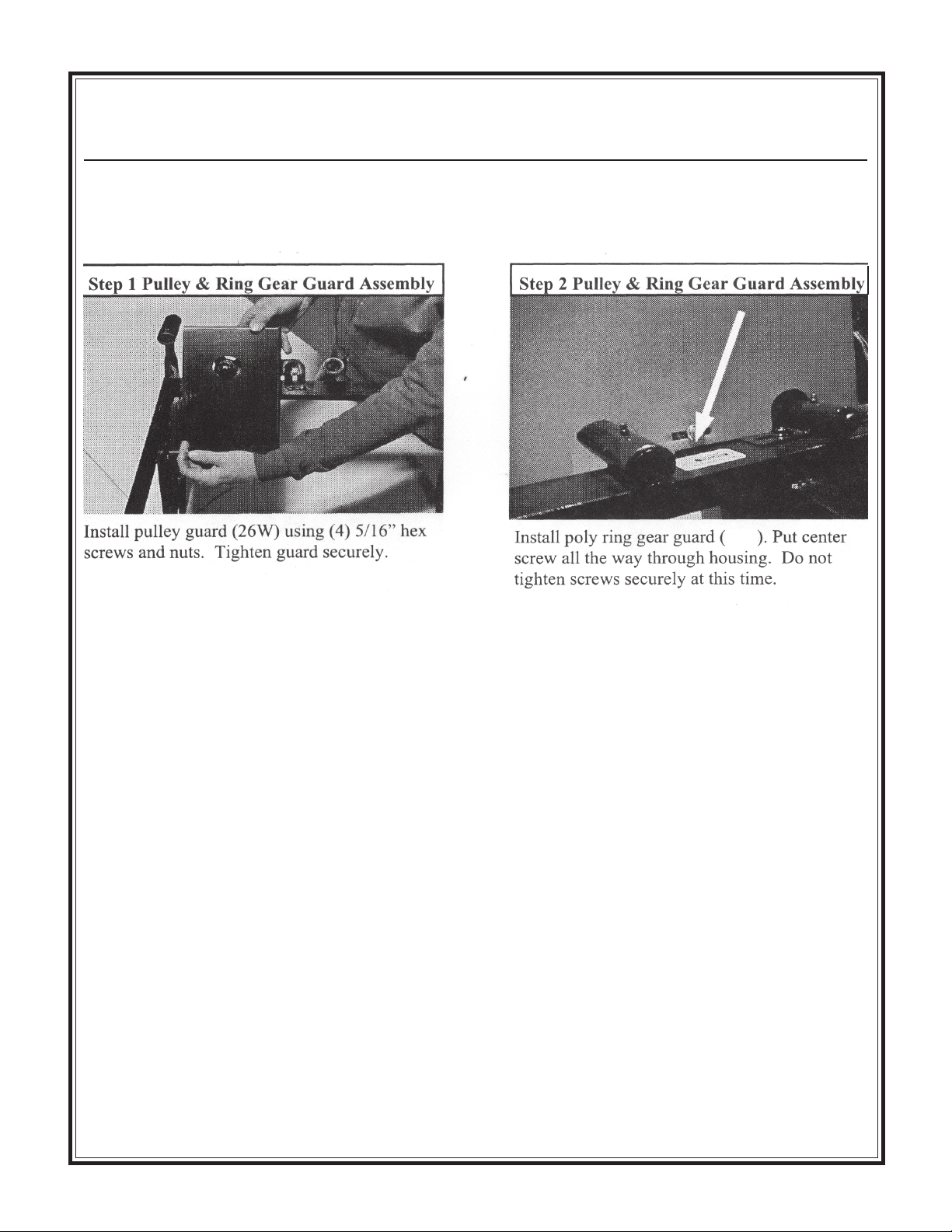
25CMP Wheelbarrow--
Maintenance
Pulley & Ring Gear Assembly
18
- 20 -
Page 17
25CMP Wheelbarrow----
Maintenance
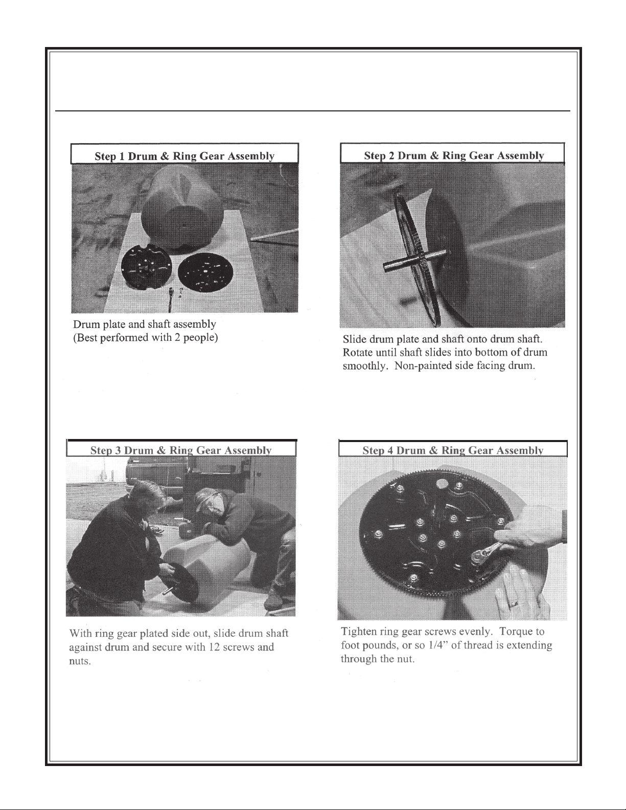
Drum & Ring Gear Assembly
- 21 -
23
Page 18
Maintenance
21
25CMP Wheelbarrow--
Drum Installation Assembly
- 22 -
Page 19
25CMP Wheelbarrow--
Maintenance
Final Assembly
* Grease two (2) fittings before every use.
- 23 -
Page 20
Maintenance
25CMPC Combination--
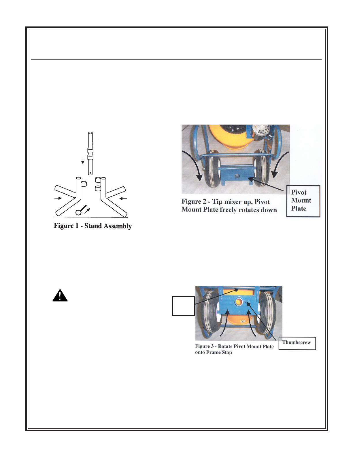
Final Assembly
Pedestal Stand Assembly
1. Place two halves of the support legs together
and insert pivot tube through the center of the
legs to join together. (Figure 1)
2. Insert locking pin through bottom of pivot tube.
Attaching Pedestal Stand to Mixer
1. Tip mixer, as if dumping contents, and place
squarely on opening of drum. The pivot
mount plate will rotate freely about the wheel
axle from its wheelbarrow stowed position.
(Figure 2)
2. Rotate pivot mount plate away from drum and
onto frame stop. Back off thumbscrew to
allow clearance for inserting pivot tube on
stand through tube. (Figure 3)
WARNING
Pivot mount plate will rotate freely about
axle when tipping mixer onto opening of
drum. Stand clear of wheel axle or
personal injury could occur.
Frame
Stop
- 24 -
Page 21
25CMPC Combination--
Maintenance
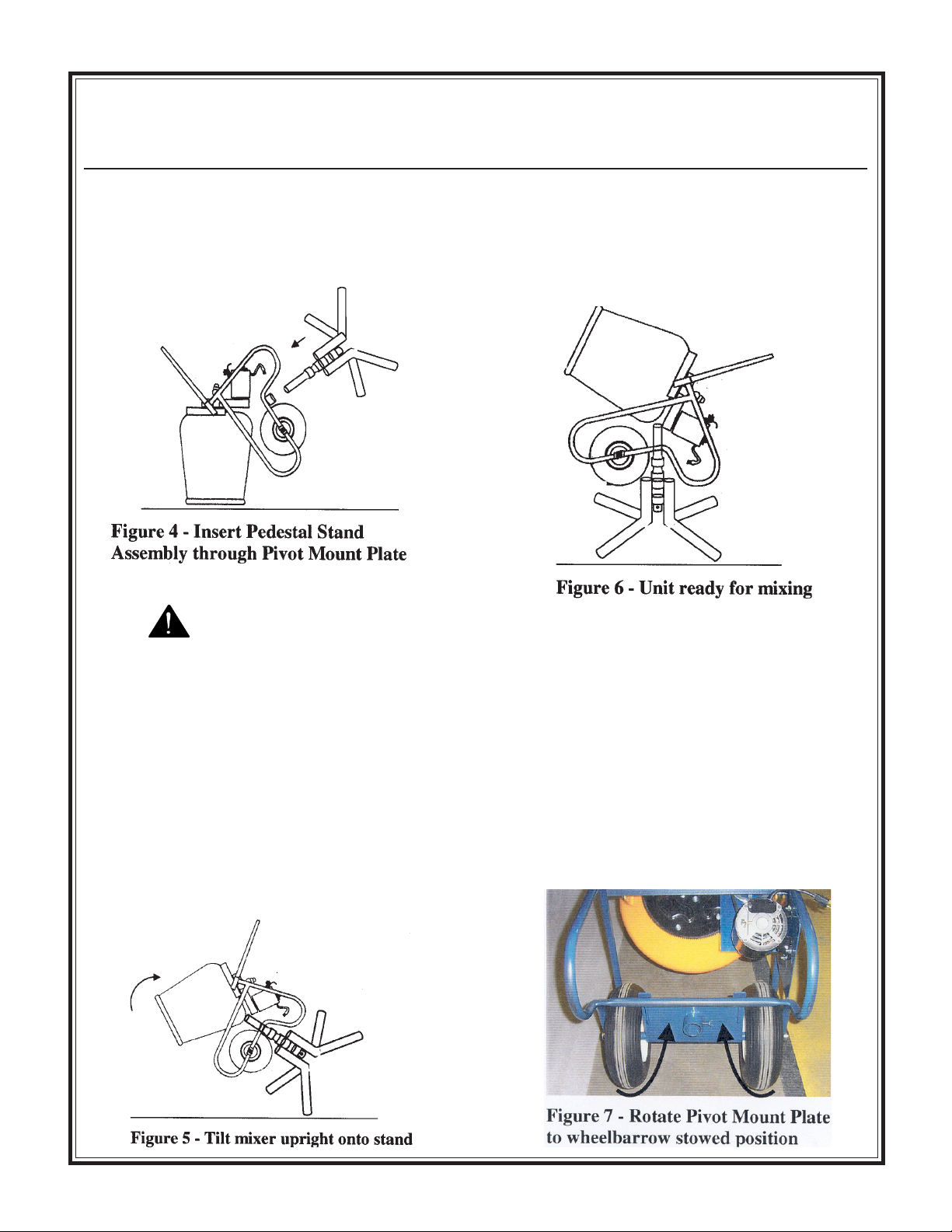
3. Insert pivot tube of pedestal stand assembly
through pivot mount and tighten thumbscrew.
(Figure 4)
Final Assembly
5. Once mixer has been tilted upright onto the
stand, the mixer should be tipped back into
mixing position before operating.
(Figure 6)
WARNING
Do not tilt mixer upright onto stand on
a wet, uneven or slippery surface.
Failure to follow this instruction could
result in personal injury or damage to
equipment.
4. Once the stand has been attached, move to
the opening side of the drum and begin
tilting the mixer upright onto the stand.
Always bend your knees and use correct
posture for lifting. Always tilt from the
front of the mixer. (Figure 5)
Converting unit back to Wheelbarrow
from Stand
To convert unit back to wheelbarrow operation
follow the directions for assembling and attaching
the pedestal stand to the unit in reverse. Make
sure to tighten thumbscrew and rotate the pivot
mount plate about the axle to its wheelbarrow
stowed position before using the unit in its
wheelbarrow function. (Figure 7)
- 25 -
 Loading...