

Page 1

BlueMod+B20/BT2.1
User Guide
Release r03
Page 2

BlueMod+B20/BT2.1
User Guide
Release r03 www.stollmann.de Page 2 of 38
Table of contents
1 Introduction ....................................................................................................... 4
2 HID Profile ......................................................................................................... 6
2.1 Setup HID ..................................................................................................... 6
2.1.1 Set Own Service Profiles (S314) ......................................................... 6
2.1.2 Class Of Device (S302) ....................................................................... 6
2.1.3 I/O Capabilities (S406) ........................................................................ 6
2.1.4 Man In The Middle Protection (S407) .................................................. 6
2.1.5 Initiate Bluetooth Link .......................................................................... 7
2.1.6 Incoming HID Connection ................................................................... 7
2.1.7 HID Data Flow Control ........................................................................ 7
2.2 HID Connection Examples ............................................................................ 8
2.2.1 Connection Example with iPhone (SSP “Just Works”) ......................... 8
2.2.2 Connection Example with iPhone (SSP “Passkey Entry”) .................... 9
2.3 HID Usage .................................................................................................. 10
2.3.1 US Key Codes .................................................................................. 10
2.3.2 Raw Mode ......................................................................................... 11
2.3.2.1 Keyboard Report ........................................................................... 11
2.3.2.2 Mouse Report ................................................................................ 11
3 Secure Simple Pairing ..................................................................................... 12
3.1 SSP Connection Examples with BlueMod+B20 ........................................... 15
3.1.1 Connection Example “Just Works” .................................................... 16
3.1.2 Connection Example “Numeric Comparison” ..................................... 17
3.1.3 Connection Example “Passkey Entry” ............................................... 18
4 Power Down Modes ........................................................................................ 19
4.1 Power Down Usage (S409) ......................................................................... 19
4.2 Wake Up Events ......................................................................................... 19
4.3 Avaialable Power Down Modes ................................................................... 20
5 Remote Configuration ...................................................................................... 21
6 Out Of Range Detach ...................................................................................... 23
6.1 RSSI Value (S411) ...................................................................................... 23
Page 3

BlueMod+B20/BT2.1
User Guide
Release r03 www.stollmann.de Page 3 of 38
6.2 RSSI Poll Time (S412) ................................................................................ 23
7 OBEX File Transfer ......................................................................................... 24
7.1 OPPC Call Request .................................................................................... 24
7.2 OPP Frame Structure ................................................................................. 24
7.3 OPP Frame Transmission ........................................................................... 25
7.3.1 OPP Data Flow Control ..................................................................... 25
7.3.2 OPP Frame Structure Example for VCARD....................................... 25
7.3.3 OPP Frame Structure Example for Text File ..................................... 26
7.3.4 OPP Frame Structure Example for Image/jpg ................................... 26
7.4 OPP Status Messages ................................................................................ 26
7.5 OPPC Transmission Examples with BlueMod+B20 .................................... 27
7.5.1 Successful OPPC Transfer ............................................................... 28
7.5.2 Failed OPPC Transfer ....................................................................... 29
7.5.3 Local OPPC Communication Error .................................................... 30
8 Communication with Apple Devices ................................................................. 31
9 Startup Timing ................................................................................................. 32
10 Firmware Upgrade ........................................................................................... 33
10.1 Device Firmware Upgrade via Serial Interface ............................................ 33
10.1.1 Prerequisites for Device Firmware Upgrade ...................................... 33
10.1.2 Stollmann BlueMod+B20 Updater ..................................................... 34
10.2 Firmware Upgrade via SPI .......................................................................... 35
10.2.1 Installation ......................................................................................... 35
10.2.2 Upgrade Procedure ........................................................................... 35
10.3 Troubleshooting .......................................................................................... 37
11 History ............................................................................................................. 38
Page 4

BlueMod+B20/BT2.1
User Guide
Release r03 www.stollmann.de Page 4 of 38
1 Introduction
This document describes the usage of the BlueMod+B20/BT2.1 Bluetooth module
featuring software version V3.100 or later.
For a detailed description of the commands refer to the BlueMod+B20/BT2.1 AT
Command Reference.
HID Profile
HID profile is available in BlueMod+B20 firmware version V3.002 and later. This
firmware implements the role device, device type combo device.
A combo device can be connected to the serial interface of the BlueMod+B20.
All Bluetooth HID specific information are described in chapter HID Profile.
SSP – Secure Simple Pairing
The headline feature of Bluetooth 2.1 is the “Secure Simple Pairing” (SSP). The
SSP is an improved experience of the pairing procedure.
For security reasons it is necessary to be able to recognize other Bluetooth devices
and control the access to the local Bluetooth device.
This pairing process can be triggered from the user to create a bond (AT+BBND)
or automatically when connecting to a service of another Bluetooth device (ATD…).
All security specific information are described in chapter Secure Simple Pairing.
Power Down Modes
The BlueMod+B20 supports different power down modes to increase the electric
power consumption.
All power down modes are described in chapter Power Down Modes.
Remote Configuration
The BlueMod+B20 includes the functionality to configure the module from the
Bluetooth interface.
More details about the required configuration and a connection example is
described in the chapter Remote Configuration.
Page 5

BlueMod+B20/BT2.1
User Guide
Release r03 www.stollmann.de Page 5 of 38
Out of Range Detach
If enabled this feature detaches an active link if a given RSSI level is exceeded.
This function is described in chapter Out of Range Detach.
OBEX File Transfer
The BlueMod+B20 includes the Object Push Profile (OBEX transfer) in firmware
V3.100 or later. The firmware supports OPP Client functionality, so outgoing calls to
an OBEX server can be made.
Detailed information about the OBEX file transfer and different connection examples
are described in the chapter OBEX File Transfer.
Communication with Apple Devices
The BlueMod+B20 supports connections to Apple devices using the SPP profile.
Detailed information about this feature are described in chapter Communication with
Apple Devices.
Firmware Startup Timing
This chapter describes the startup timing of the Bluemod+B20.
Firmware Upgrade
The firmware of the BlueMod+B20 can be updated via RS232 or SPI interface.
These different upgrade procedures are described in chapter Firmware Upgrade.
Page 6

BlueMod+B20/BT2.1
User Guide
Release r03 www.stollmann.de Page 6 of 38
2 HID Profile
This chapter describes the usage of the HID profile in the AT interface of the
BlueMod+B20/SPP/HID.
2.1 Setup HID
This chapter describes the steps needed to setup a HID connection using
BlueMod+B20/SPP/HID.
2.1.1 Set Own Service Profiles (S314)
The BlueMod+B20 firmware sets the own service profile to SPP (0x01) by default.
To use HID the register S314 has to be set to 0x10. To set more than one profile at
the same time, refer to the detailed description of S314 in the document
BlueMod+B20/BT2.1 AT Command Reference.
ATS314=0x10
Set HID profile
2.1.2 Class Of Device (S302)
The class of device has to be set in addition to S314. Some devices show only
devices in their inquiry results that match a special major/minor class code.
For HID devices the major device class shall be set to “peripheral”, the minor device
class shall be set to “combo”, “keyboard” or “pointing” device.
For detailed description of S302 please read the document BlueMod+B20/BT2.1 AT
Command Reference.
2.1.3 I/O Capabilities (S406)
As a HID combo device implies keyboard functionality the I/O capabilities shall be
set to keyboard.
ATS406=2
Set I/O capabilities to keyboard only
2.1.4 Man In The Middle Protection (S407)
The HID device shall be set to the same man in the middle protection setting the
HID host side uses. In principle a combo device shall support man in the middle
protection because it is capable to enter a key and SSP using man in the middle
protection is the most secure connection in Bluetooth 2.1.
ATS407=1
Set man in the middle protection on
Page 7

BlueMod+B20/BT2.1
User Guide
Release r03 www.stollmann.de Page 7 of 38
2.1.5 Initiate Bluetooth Link
To set up a connection from the BlueMod+B20 to a remote HID host, the ATD
command is used with the profile identifier HID as described in the example below:
ATD 0080371443AB,HID
Connect to Bluetooth device 0080371443AB using the remote service
profile HID
Note: The firmware does not initiate an automatic reconnect, so reconnects have
to be done manually by sending an “ATD” command triggered by the controller, or
by the HID host application.
2.1.6 Incoming HID Connection
If a HID host initiates a connection to the BlueMod+B20 a RING event is generated
in the AT interface. If extended result codes are enabled (ATW1), the event gives
information about Bluetooth address of the initiating device, UUID and profile.
RING·000461851832·1124·HID
2.1.7 HID Data Flow Control
During a HID connection the BlueMod+B20 supports the serial hardware flow
control (RTS/CTS). Please note to control the serial status line “UART_RTS“
(pin 24) of the BlueMod+B20 module in case of an active flow control situation.
Page 8
BlueMod+B20/BT2.1
User Guide
Release r03 www.stollmann.de Page 8 of 38
2.2 HID Connection Examples
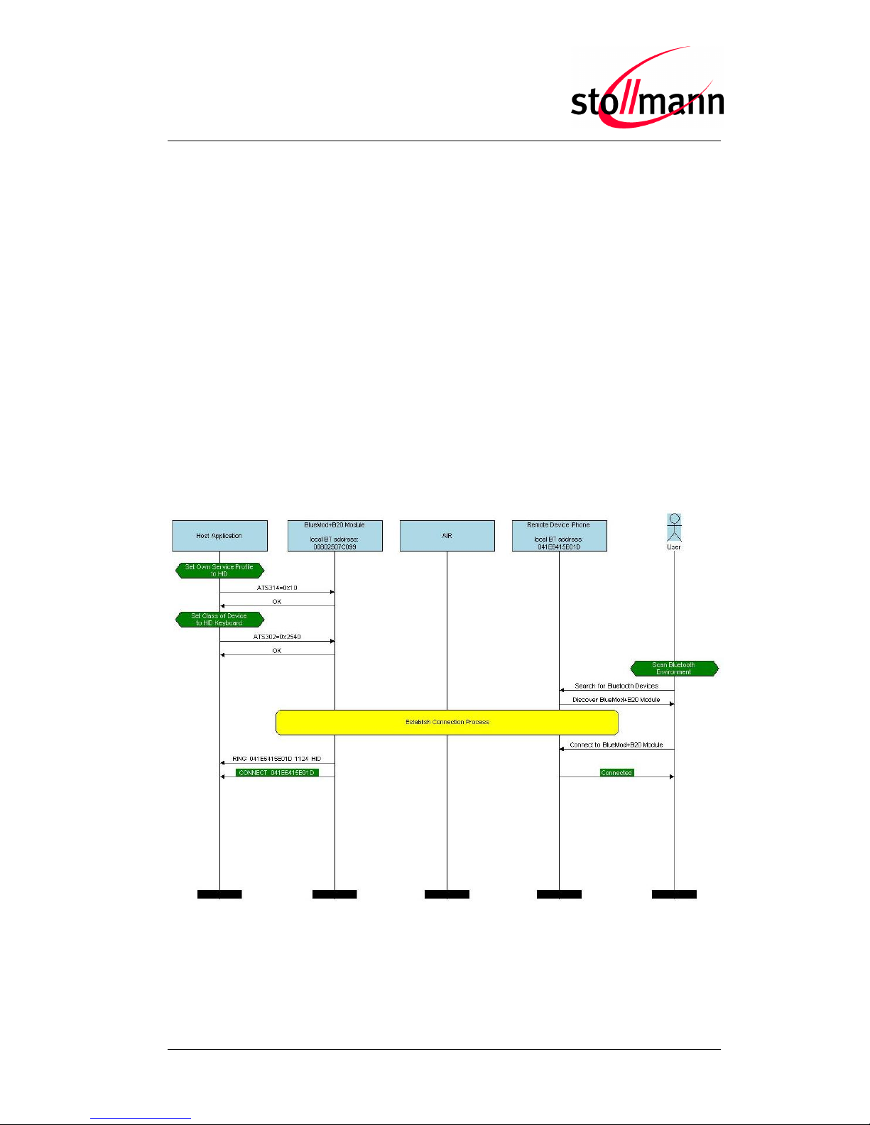
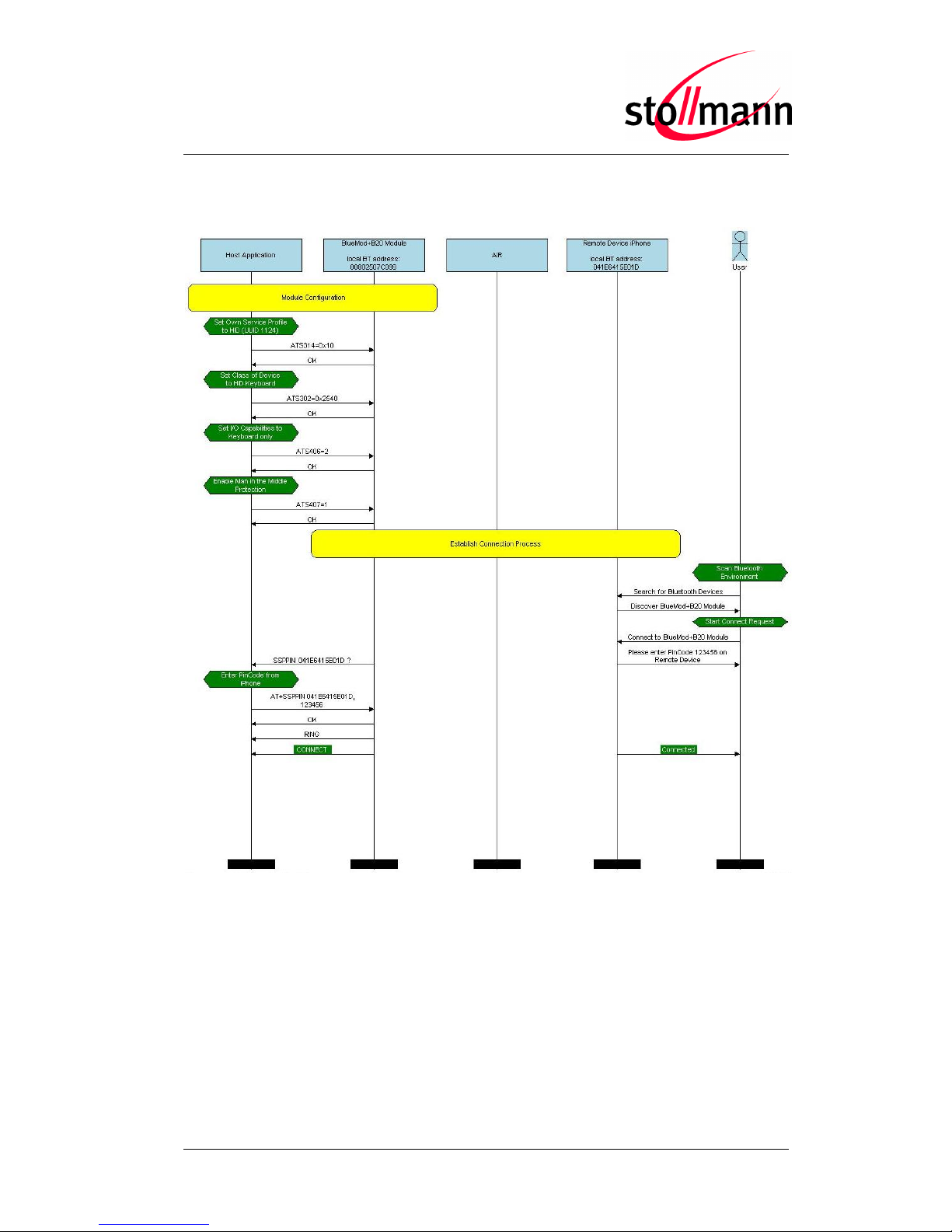
The following flow charts will give an example for the configuration and connection
establishment using the BlueMod+B20 and an iPhone with and without SSP.
Onto these flow charts the local Bluetooth device (BT device A) is a BlueMod+B20.
The destination is a iPhone with iOS 5.x.
The “Application” part will simulate the device at the end (DTE) which communicates
to the local Bluetooth device with configuration commands.
The box called “AIR” will signal which part of communication will be transmitted over
Bluetooth to the destination side.
The configuration commands and responses within the flow charts are described in
the BlueMod+B20/BT2.1 AT Command Reference.
2.2.1 Connection Example with iPhone (SSP “Just Works”)
Page 9
BlueMod+B20/BT2.1
User Guide
Release r03 www.stollmann.de Page 9 of 38
2.2.2 Connection Example with iPhone (SSP “Passkey Entry”)
Page 10

BlueMod+B20/BT2.1
User Guide
Release r03 www.stollmann.de Page 10 of 38
2.3 HID Usage
The firmware supports an US HID keyboard layout to send standard keys. To send
special keys the raw mode is implemented.
2.3.1 US Key Codes
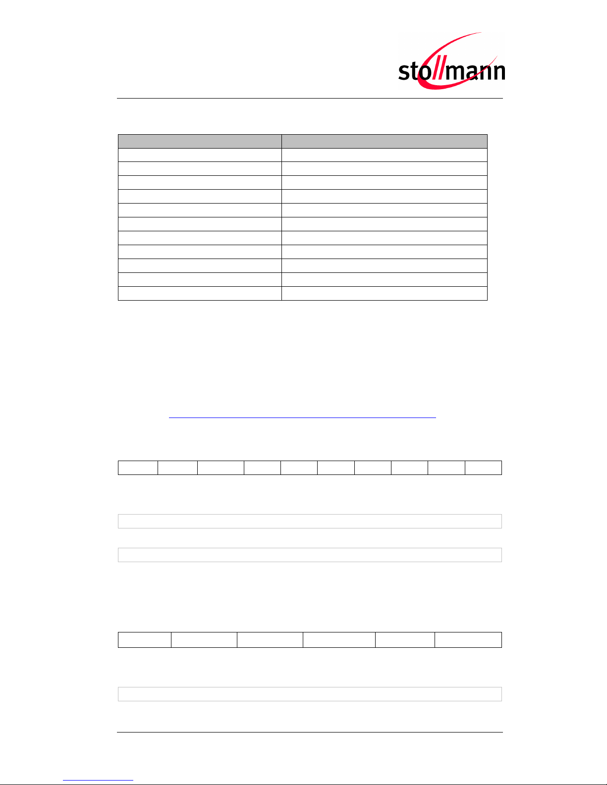
To send a key described in the table, the appropriate key code has to be sent to the
host.
Key code
Description
0x00
Left control + space
0x01
Left control + a
0x02
Left control + b
0x03
Left control + c
0x04
Left control + d
0x05
Left control + e
0x06
Left control + f
0x07
Left control + g
0x08
Backspace
0x09
Tab
0x0A
Return
0x0B
Left control + k
0x0C
Left control + l
0x0D
Return
0x0E
Left control + n
0x0F
Left control + o
0x10
Left control + p
0x11
Left control + q
0x12
Left control + r
0x13
Left control + s
0x14
Left control + t
0x15
Left control + u
0x16
Left control + v
0x17
Left control + w
0x18
Left control + x
0x19
Left control + y
0x1A
Left control + z
0x1B
ESC
0x1C – 0x1F
Not used
0x20 – 0x7E
Corresponding ASCII character
0x7F
Backspace
0x80
Cursor up
0x81
Cursor right
Page 11
BlueMod+B20/BT2.1
User Guide
Release r03 www.stollmann.de Page 11 of 38
2.3.2 Raw Mode
To transmit special keys or mouse keys, the firmware supports sending HID reports
in raw mode. The frame starts with 0x9f as identifier for raw mode. The following
bytes select keyboard (0x01) or mouse report (0x02).
The full description of key codes can be found in the “USB HID Usage Tables”
document: http://www.usb.org/developers/devclass_docs/Hut1_11.pdf
2.3.2.1 Keyboard Report
0x9f
0x01
modifier
0x00
Code1
Code2
Code3
Code4
Code5
Code6
Up to six key codes can be sent at a time.
Example (key “a” down):
0x9f 0x01 0x00 0x00 0x04 0x00 0x00 0x00 0x00 0x00
Example (key release):
0x9f 0x01 0x00 0x00 0x00 0x00 0x00 0x00 0x00 0x00
To release keys, a frame consisting a 0x00 instead of the corresponding code has to
be sent.
2.3.2.2 Mouse Report
0x9f
0x02
buttons
x-step
y-step
wheel
Example (mouse 1 pressed):
0x9f 0x02 0x01 0x00 0x00 0x00
Key code
Description
0x82
Cursor down
0x83
Cursor left
0x84
Insert
0x85
Delete
0x86
Home
0x87
End
0x88
Page up
0x89
Page down
0x8A – 0x9E
Not used
0x9F
Raw mode identifier
0xA0 – 0xFE
Not used
Page 12

BlueMod+B20/BT2.1
User Guide
Release r03 www.stollmann.de Page 12 of 38
3 Secure Simple Pairing
For security reasons it is necessary to be able to recognize other Bluetooth devices
and control the access to the local Bluetooth device.
The “Secure Simple Pairing” (SSP) is the headline feature of Bluetooth 2.1 and the
improved experience of the pairing procedure.
SSP is mandatory for Bluetooth 2.1 devices and cannot be switched off.
A Bluetooth 2.1 device may only use “legacy pairing” to interoperate with a
Bluetooth 2.0 or earlier device.
The pairing process can be triggered from the user to create a bond (AT+BBND)
or automatically when connecting to a service of another Bluetooth device (ATD…).
SSP is configurable using the parameters for I/O capabilities (S406) and a man in
the middle protection (S407).
S406 sets the input and output capabilities of the device used for SSP.
Value
Description
0
Display only
1
Display Yes/No
2
Keyboard only
3
No input no output (default)
S407 controls the man in the middle (MITM) protection of the device during SSP.
Value
Description
0
Man in the middle protection disabled (default)
1
Man in the middle protection enabled
In case the user choose a scenario where MITM protection is not allowed but one of
the communication devices is configured to MITM protection, the pairing is refused.
Page 13

BlueMod+B20/BT2.1
User Guide
Release r03 www.stollmann.de Page 13 of 38
SSP defines the following association models based on the Input/Output (I/O)
capabilities of the two devices:
Just Works:
This method is used when at least one of the devices does not have display
capability of six digits and also is not capable of entering six decimal digits using a
keyboard or any other means (no I/O).
This method does not provide MITM protection.
Compared to the legacy pairing with a fixed PIN, the security level provided by this
method is much higher.
Numeric Comparison:
If both devices have a display and both sides can accept a “Yes/No” user input, they
may use Numeric Comparison. This method displays a six digit numeric code on
each device. The user shall compare the numbers to ensure they are identical. If the
comparison succeeds, the user(s) shall confirm pairing on the device(s) that can
accept an input.
This method provides MITM protection, assuming the user confirms on both devices
and actually performs the comparison properly.
Passkey Entry:
This method may be used between a device with a display and a device with
numeric keypad entry (such as a keyboard), or two devices with numeric keypad
entry.
In the first case, the display is used to show a six digit numeric code to the user,
who then enters the code on the keypad.
In the second case, the user of each device enters the same six digit numeric code.
Both cases provide MITM protection.
Legacy Pairing: (Bluetooth 2.0 compatible pairing mechanism)
In this case both devices needs to enter the same PIN code of minimum four digits.
The BlueMod+B20 uses the PIN code saved in the local register S318
(compare: BlueMod+B20/BT2.1 AT Command Reference).
Possible combinations of I/O capabilities and the possibility of MITM protection are
listed in the table below. For each case of the “MITM protection” an example of the
serial messages between the BlueMod+B20 and the DTE are listed.
Page 14

BlueMod+B20/BT2.1
User Guide
Release r03 www.stollmann.de Page 14 of 38
Remote
device
B20
Display only
Display Yes/No
Keyboard only
No input no output
Display only
ATS406=0
Just Works
(numeric comparison, both
automatic confirmation)
No MITM protection
Numeric comparison
(both displayed, one automatic
confirm)
No MITM protection
Passkey entry
(one display, one input)
MITM protection
SSPPIN <BT addr> <passkey>
Just Works
(Numeric comparison, both
automatic confirmation)
No MITM protection
Display Yes/No
ATS406=1
Numeric comparison
(both displayed, one automatic
confirm)
No MITM protection
Numeric comparison
(both displayed, both confirm)
MITM protection
SSPCONF <BT addr> <passkey> ?
AT+SSPCONF <BT addr>, 1
Passkey entry
(one display, one input)
MITM protection
SSPPIN <BT addr> <passkey>
Just Works
(numeric comparison, both
automatic confirmation)
No MITM protection
Keyboard only
ATS406=2
Passkey entry
(one display, one input)
MITM protection
SSPPIN <BT addr> ?
AT+SSPPIN <BT addr>,<passkey>
Passkey entry
(one display, one input)
MITM protection
SSPPIN <BT addr> ?
AT+SSPPIN <BT addr>,<passkey>
Passkey entry (both input)
MITM protection
SSPPIN <BT addr> ?
AT+SSPPIN <BT addr>,<passkey>
Just Works
(numeric comparison, both
automatic confirmation)
No MITM protection
No input
no output
ATS406=3
Just Works
(numeric comparison, both
automatic confirmation)
No MITM protection
Just Works
(numeric comparison, both
automatic confirmation)
No MITM protection
Just Works
(numeric comparison, both
automatic confirmation)
No MITM protection
Just Works
(numeric comparison, both
automatic confirmation)
No MITM protection
Green color: B20 output message SSPPIN <BT addr> ? (example)
Blue color: B20 input request : AT+SSPPIN <BT addr> <passkey> (example)
Page 15

BlueMod+B20/BT2.1
User Guide
Release r03 www.stollmann.de Page 15 of 38
3.1 SSP Connection Examples with BlueMod+B20
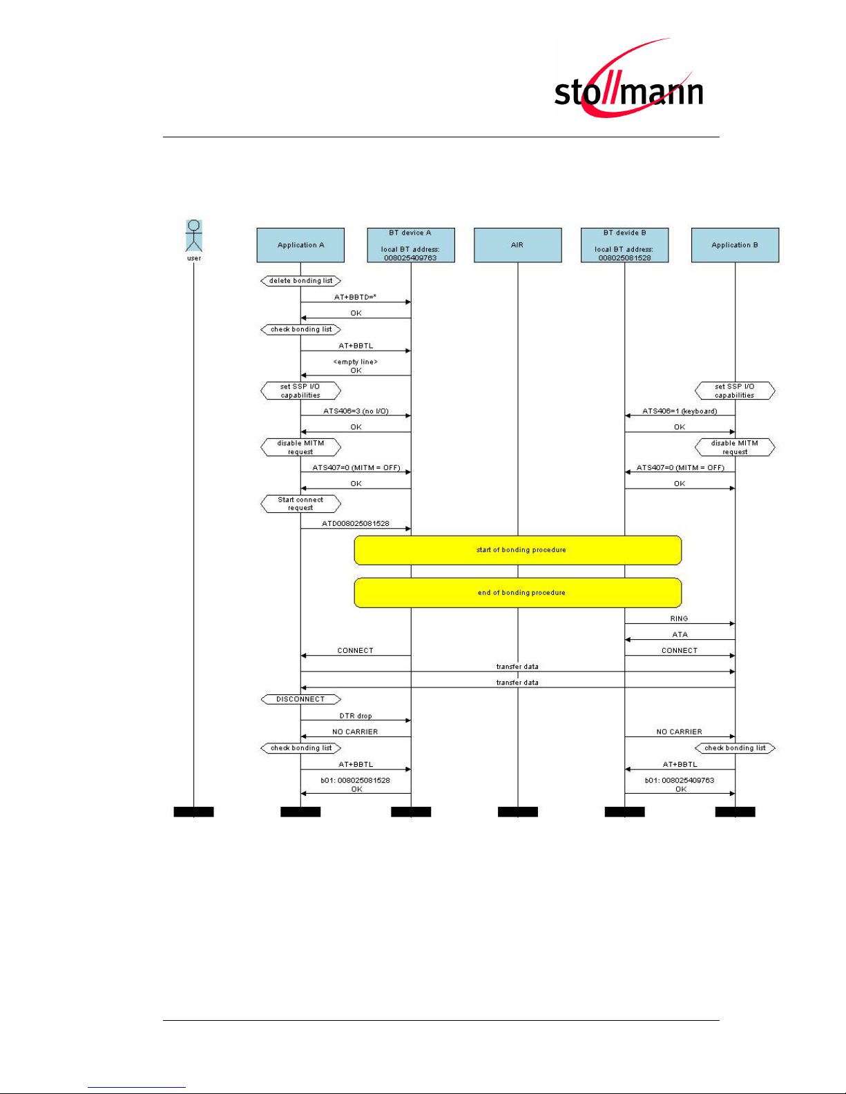
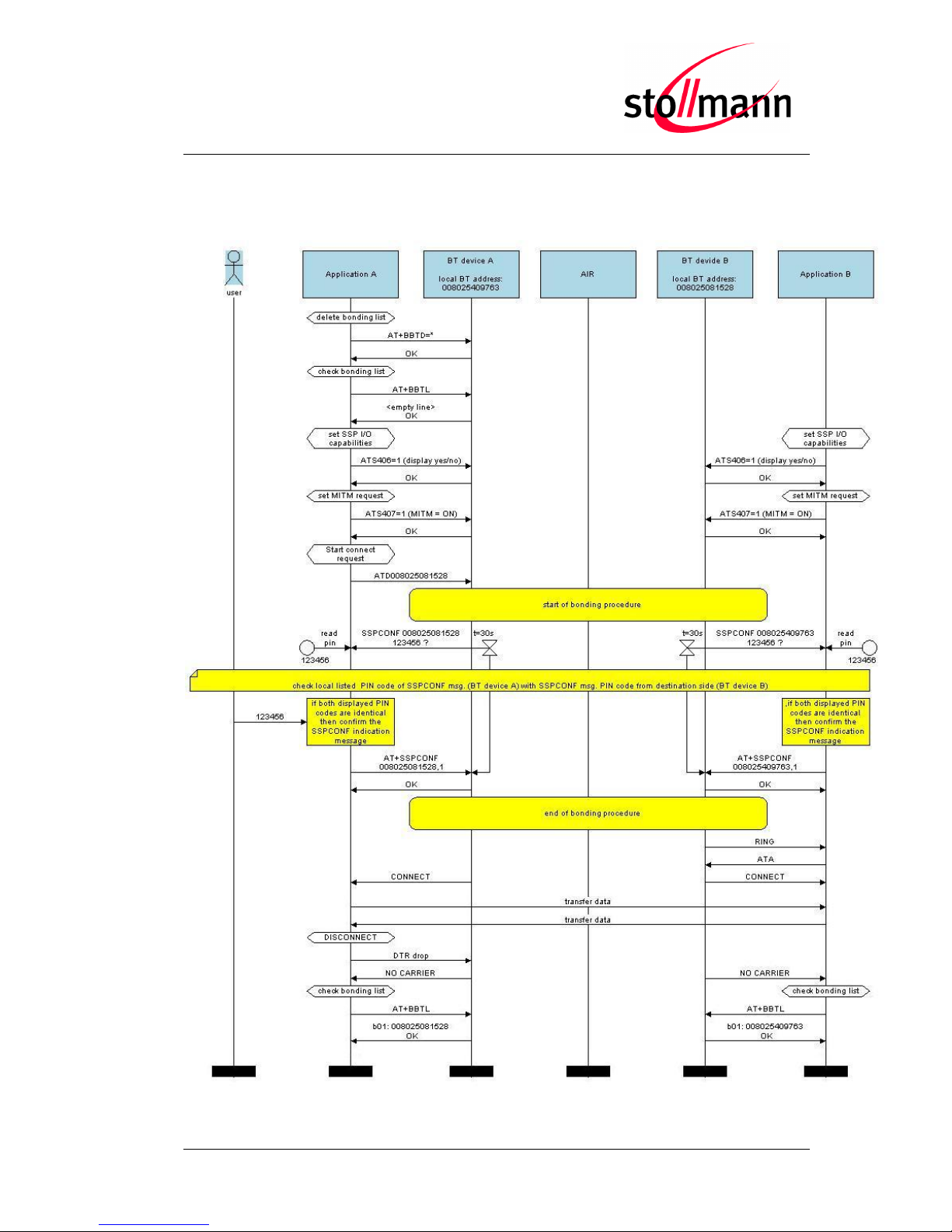
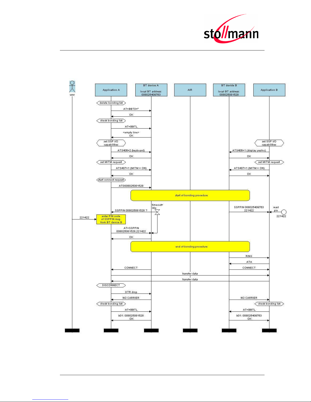
The following flow charts will give an example for the different SSP authentication
methods “just works”, “numeric comparision” and “passkey entry” within an active
outgoing call request from the BlueMod+B20.
Onto these flow charts the local Bluetooth device (BT device A) and the destination
side (BT device B) are configured with a BlueMod+B20. The destination can be
changed to each other Bluetooth 2.1 device.
The “Application” part will simulate the device at the end (DTE) which communicates to
the local Bluetooth device with configuration commands.
The box called “AIR” will signal which part of communication will be transmitted over
Bluetooth to the destination side.
The interesting part of the bonding procedure is placed between the yellow boxes “start
of bonding procedure” and “end of bonding procedure”.
All serial commands between the “Application A/B” and the “BT device A/B” out of the
bonding procedure are used for further configuration of SSP.
The configuration commands and responses within the flow charts are described in the
BlueMod+B20/BT2.1 AT Command Reference.
Page 16
BlueMod+B20/BT2.1
User Guide
Release r03 www.stollmann.de Page 16 of 38
3.1.1 Connection Example “Just Works”
with I/O capabilities combination “no I/O” and “keyboard”
Page 17
BlueMod+B20/BT2.1
User Guide
Release r03 www.stollmann.de Page 17 of 38
3.1.2 Connection Example “Numeric Comparison”
with I/O capabilities combination “display yes/no” on both sides
Page 18
BlueMod+B20/BT2.1
User Guide
Release r03 www.stollmann.de Page 18 of 38
3.1.3 Connection Example “Passkey Entry”
with I/O capabilities combination “keyboard” and “display yes/no”
Page 19

BlueMod+B20/BT2.1
User Guide
Release r03 www.stollmann.de Page 19 of 38
4 Power Down Modes
This chapter describes different power down modes and the prior conditions for these
modes.
The power down mode is available on BlueMod+B20/SPP/HID in firmware V3.002 and
later.
4.1 Power Down Usage (S409)
The power down functionality is disabled by default.
It can be enabled by setting the parameter S409 and additionally by controlling the
serial input status line DTR (Pin no. 7, PIO4, „RTC-IN‟).
ATS409=0
Disable deep sleep (default)
ATS409=1
Enable deep sleep
4.2 Wake Up Events
If enabled, the device sleeps if no activity on the AT interface is detected for 250 ms.
The device wakes up on the following events:
An incoming connection
(only available if page scan is enabled, S316=2 or 3)
Activating serial status line DTR
(0V on LV-TTL level)
Activity on RX UART line, e.g. sending a character on the UART interface
(please note that the module will reach back to the power down mode after
250 ms of no activity on the RX UART)
Waking up the device by activity on RX UART line is not recommenced because the
first character is lost, so this method can result in loss of data.
Waking up by an incoming connection implies active page scans (S316). This leads to
higher power consumption in the power down mode.
Page 20

BlueMod+B20/BT2.1
User Guide
Release r03 www.stollmann.de Page 20 of 38
4.3 Avaialable Power Down Modes
Power Down Mode
Conditions
Power Consumption
No Power Down
normal operation
(idle)
Power Down deactivated (S409=0)
Page/inquiry scan enabled (S316=3)
DTR active (0V on LV-TTL level)
20pprox.. 2.5 mA
Power Down
Power Down active (S409=1)
Page scan enabled (S316=2)
Accept incoming call
when DTR is inactive (AT&D4)
DTR inactive (3.3V on LV-TTL level)
20pprox.. 1.1 mA
Deep Sleep
Power Down active (S409=1)
No page/inquiry scan (S316=0)
DTR inactive (3.3V on LV-TTL level)
20pprox.. 0.04 mA
RESET state
20pprox.. 2.3 mA
Page 21

BlueMod+B20/BT2.1
User Guide
Release r03 www.stollmann.de Page 21 of 38
5 Remote Configuration
The BlueMod+B20 can be configured via Bluetooth by using another Bluetooth device.
Make sure the BlueMod+B20 is powered on and in range of the local Bluetooth device.
By default the configuration port of the BlueMod+B20 is not accessible and not visible.
To make it visible and accessible for other Bluetooth devices the configuration port
must be set to “accessible and visible” first (ATS403=2).
Initiate a new scan of the Bluetooth area. When the BlueMod+B20 is found perform a
service discovery. In the result you will get 2 services (ports):
“SPP” (UUID 0x1101, service channel 1)
“Remote Config” (UUID 0x1101, service channel 2 or other)
Connect to the “Remote Config” and open the terminal program at the appropriate
COM port.
Once the Bluetooth connection is established successfully (signaled with “RC ONLINE”
response at the remote BlueMod+B20) the BlueMod+B20 answers the commands in
the UART of the remote side. Now you can configure the remote BlueMod+B20 using
the AT commands. You can close the connection by using the ATH command
(signaled with “RC OFFLINE” response at the remote BlueMod+B20).
The configuration port of the BlueMod+B20 can be disabled using the ATS403=0
command.
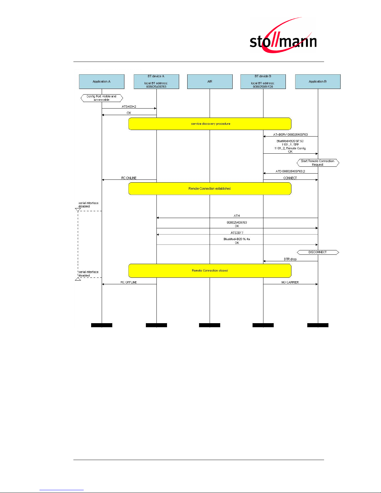
The following flow chart will give an example of the remote configuration connection
between two BlueMod+B20 modules (BT device A + B).
The Bluetooth device (BT device A) enables the visibility and the access of the “remote
config port” first (ATS403=2). After that the BT device B starts a service discovery to
BT device A followed by a remote connection.
During the remote connection BT device B reads out the BT address of BT device A
(ATI4) and the local device name (ATS301?).
The remote connection is closed from the BT device B with a local DTR drop.
The “Application” part simulates the device at the end (DTE) which communicates to
the local Bluetooth device with configuration commands.
The box called “AIR” signals which part of communication will be transmitted over
Bluetooth to the destination side.
Page 22
BlueMod+B20/BT2.1
User Guide
Release r03 www.stollmann.de Page 22 of 38
Page 23

BlueMod+B20/BT2.1
User Guide
Release r03 www.stollmann.de Page 23 of 38
6 Out Of Range Detach
If enabled this feature detaches an active link if a given RSSI value is exceeded.
It can be activated by setting the register S410 to 1, the default setting of S410 is 0.
ATS410=1
Enable out of range detach
6.1 RSSI Value (S411)
The register S411 sets the RSSI value for the “out of range detach” feature. If set to -80
the link is detached if the measured RSSI exceeds this value. This value can be
configured by the user according the existing scenario.
The application compares the mean value of the last 3 measured RSSI values to the
value set in S411.
ATS411=-80
Set RSSI value to -80db
6.2 RSSI Poll Time (S412)
The register S412 sets the poll time in milliseconds for measuring the RSSI value for
the “out of range detach” feature. The default value is 3000, the maximum value is
10000. Changing this register affects the processing time of the “out of range detach”
because the polling interval for RSSI is changed.
ATS412=4000
Set RSSI poll time to 4 seconds
Page 24

BlueMod+B20/BT2.1
User Guide
Release r03 www.stollmann.de Page 24 of 38
7 OBEX File Transfer
This chapter describes the Object Push Profile (OBEX transfer) implementation in the
BlueMod+B20 firmware.
This Bluetooth module supports the Object Push Profile in client mode only (OPP
client). Therefore the Bluetooth module initiates an outgoing call to the OBEX server
side.
The OPP client call request, the OPP frame structure and different connection
examples will be described below.
7.1 OPPC Call Request
To initiate a Bluetooth connection using the service profile “OPP” the dial command
needs the additional identifier “OPPC” or the UUID “1105”.
Example:
ATD<Bluetooth address>,OPPC
ATD<Bluetooth address>,1105
After the destination device accepts the call request from the BlueMod+B20 module the
message “CONNECT” is sent to the local serial interface.
7.2 OPP Frame Structure
After the connection is established the BlueMod+B20 can send the OPP frame as
specified below:
Length
<sp>
Filename
<sp>
MIME Type
<sp>
Data
Length
Length of the data field, 8 digits, ASCII decimal coded, filled with
leading zero
Filename
File name of the transmitted data, i.e “test.vcf”
MIME Type
Type according RFC 2045, i.e. “image/jpeg” or “text/plain”
Data
Data (payload) of the transmitted object
<sp>
Field separator <SPACE> (0x0D)
Page 25

BlueMod+B20/BT2.1
User Guide
Release r03 www.stollmann.de Page 25 of 38
7.3 OPP Frame Transmission
The BlueMod+B20 is able to transmit data frames with different object types like:
vCal
vCard
vMsg
vNote
files like text files, images, etc.
7.3.1 OPP Data Flow Control
During a OPP frame transmission the BlueMod+B20 supports the serial hardware flow
control (RTS/CTS). Please note to control the serial status line “UART_RTS“
(pin 24) of the BlueMod+B20 module in case of an active flow control situation.
If the application does not react to the serial CTS status line of the BlueMod+B20
module some data of the OPP frame will get lost.
The following examples will give an overview about the object specific frame structure.
7.3.2 OPP Frame Structure Example for VCARD
Length 00000284
Filename vcard_Mustermann.vcf
MIME Type text/x-vcard
Data BEGIN:VCARD
VERSION:3.0
N:Mustermann;Max
FN:Max Mustermann
ORG:Wikipedia
URL:http://de.wikipedia.org/
EMAIL;TYPE=INTERNET:max.mustermann@example.org
TEL;TYPE=voice,work,pref:+49 1234 56788
ADR;TYPE=intl,work,postal,parcel:;;Musterstraße 1;Musterstadt; ;12345;
Germany
END:VCARD
BEGIN:VCARD
VERSION:3.0
N:Mustermann;Max
FN:Max Mustermann
ORG:Wikipedia
URL:http://de.wikipedia.org/
EMAIL;TYPE=INTERNET:[email protected]
TEL;TYPE=voice,work,pref:+49 1234 56788
ADR;TYPE=intl,work,postal,parcel:;;Musterstraße
1;Musterstadt;;12345;Germany
END:VCARD
Page 26
BlueMod+B20/BT2.1
User Guide
Release r03 www.stollmann.de Page 26 of 38
7.3.3 OPP Frame Structure Example for Text File
Length 00000099
Filename testfile.txt
MIME Type text/plain
Data BEGIN:VCARD
VERSION:3.0
7.3.4 OPP Frame Structure Example for Image/jpg
Length 00194256
Filename Stollmann_Logo.jpg
MIME Type image/jpg
Data
7.4 OPP Status Messages
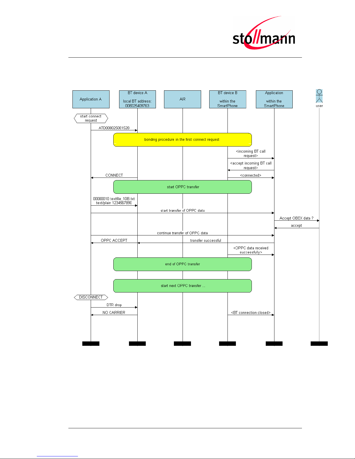
The BlueMod+B20 is transmitting the OPP frame to the destination side.
In case of a successful transmission the BlueMod+B20 module is reporting the
following status message to the local serial interface: “OPPC ACCEPT”.
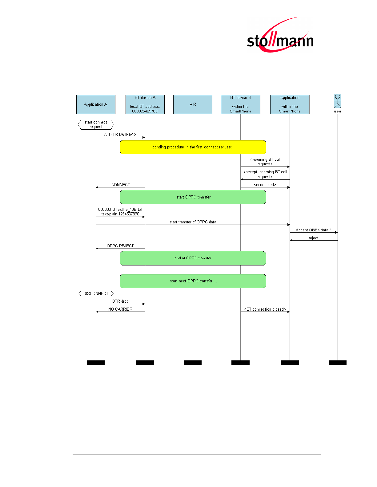
If the destination side (OPP server) rejects the received OPP frame the BlueMod+B20
reports a negative status message “OPPC REJECT”.
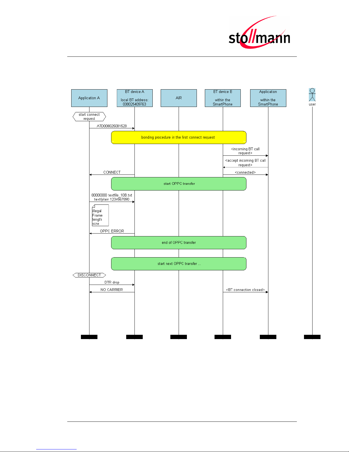
In case of a local procedure (syntax error) the BlueMod+B20 creates the following
negative status message: “OPPC ERROR”.
Text
Meaning
OPPC ACCEPT
Successful OPPC data transmission
OPPC REJECT
Failed OPPC data transmission
OPPC ERROR
Local OPPC frame error, OPPC syntax error
These different status messages will be also listed in different OPPC transmission
examples in the next chapter.
1234567890 1234567890 1234567890 1234567890 1234567890
1234567890 1234567890 1234567890 123456789
Page 27

BlueMod+B20/BT2.1
User Guide
Release r03 www.stollmann.de Page 27 of 38
7.5 OPPC Transmission Examples with BlueMod+B20
The following flow charts will give examples with different OPPC transmission results
between the BlueMod+B20 and the reference device. In our situation the reference
device is a smart phone.
The “Application” part will simulate the device at the end (DTE) which communicates to
the local Bluetooth device or the application within the smart phone.
The box called “AIR” will signal which part of communication will be transmitted over
Bluetooth to the destination side.
The configuration commands and responses within the flow charts are described in the
BlueMod+B20/BT2.1 AT Command Reference.
Page 28
BlueMod+B20/BT2.1
User Guide
Release r03 www.stollmann.de Page 28 of 38
7.5.1 Successful OPPC Transfer
Page 29
BlueMod+B20/BT2.1
User Guide
Release r03 www.stollmann.de Page 29 of 38
7.5.2 Failed OPPC Transfer
Page 30
BlueMod+B20/BT2.1
User Guide
Release r03 www.stollmann.de Page 30 of 38
7.5.3 Local OPPC Communication Error
Page 31

BlueMod+B20/BT2.1
User Guide
Release r03 www.stollmann.de Page 31 of 38
8 Communication with Apple Devices
To accept connections from Apple devices the service record of the BlueMod+B20
contains an Apple specific UUID. This UUID is implemented in the standard Serial Port
Profile (1101) service record of the BlueMod+B20.
To connect to an Apple device, the user shall connect to the service named “Wireless
iAP” of the Apple device. The ATD command has to be used with the corresponding
service channel number. Use the BSRV command to find the channel number of the
service named “Wireless iAP”.
To make the BlueMod+B20 visible to Apple devices the Class of Device (S302) has to
be set to a value listed in the table below:
Major Service Class
Major Device Class
Minor Device Class
S302
Audio + Rendering
Audio / Video
Portable Audio
0x24041C
Handsfree
0x240408
Headset
0x240404
Loadspeaker
0x240414
Headphones
0x240418
Hifi Audio
0x240428
Car Audio
0x240420
Wearable
Watch
0x240704
Jacket
0x24070C
Helmet
0x240710
Glasses
0x240714
Page 32
BlueMod+B20/BT2.1
User Guide
Release r03 www.stollmann.de Page 32 of 38
/Reset
LED1
/DCD
/DSR
/RI
130ms
416
ms
Firmware Startup
Initializing
Command ready
0,55
s
/RTS
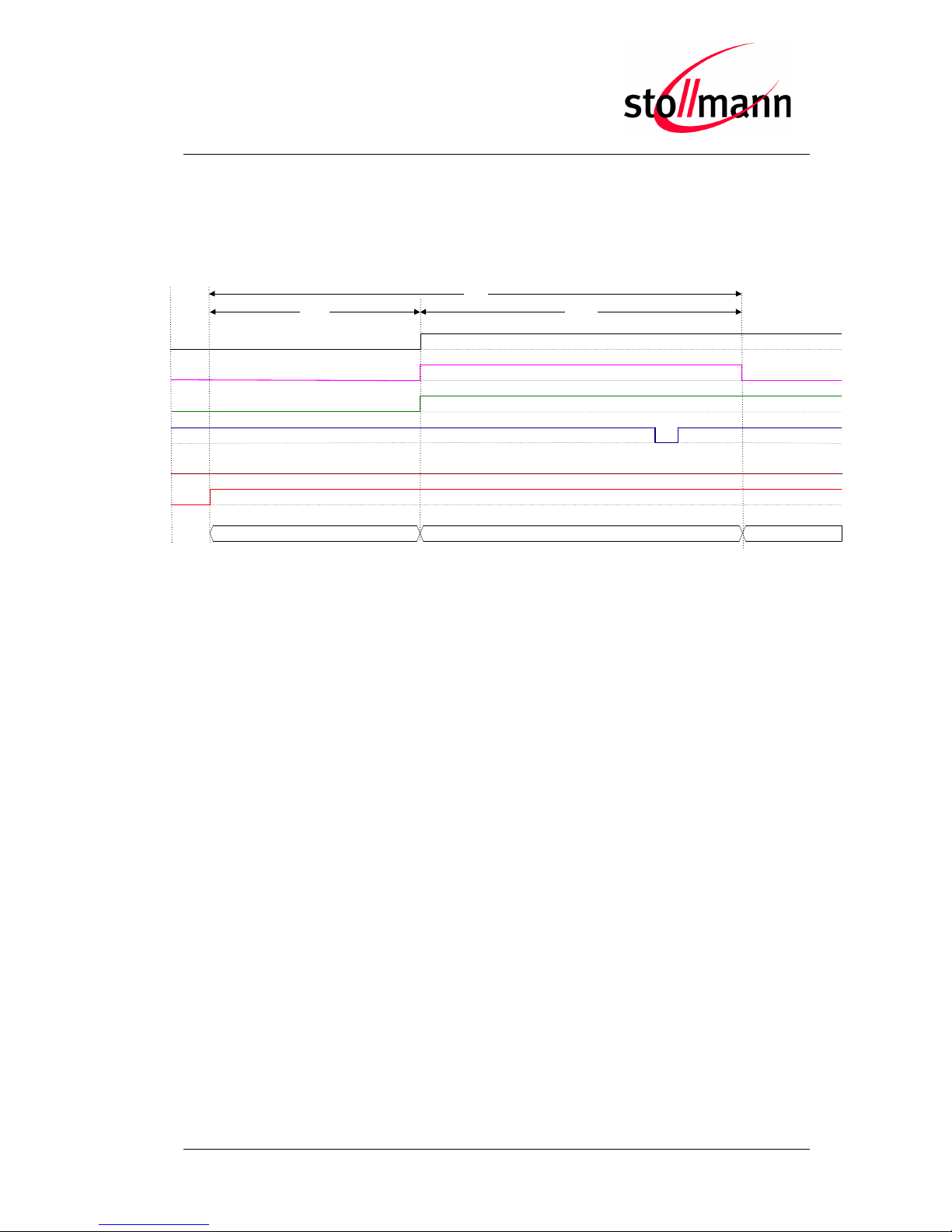
9 Startup Timing
The following diagram shows the startup timing of the BlueMod+B20 based on
firmware version 3.100.
The firmware is command ready 0.55s after the reset has been released.
For further information regarding startup timing of other firmware versions please
contact stollmann.
Page 33

BlueMod+B20/BT2.1
User Guide
Release r03 www.stollmann.de Page 33 of 38
10 Firmware Upgrade
This chapter describes the firmware upgrade procedure for a BlueMod+B20 via RS232
or SPI.
The software used for the upgrade is able to run on the following Win32 platforms:
Windows XP
Windows Vista
Note: Testing was only carried out on Vista Ultimate and XP Professional platforms;
however experience suggests that the described software runs on all XP platforms
and all Vista 32-bit platforms.
10.1 Device Firmware Upgrade via Serial Interface
The DFU software package provides a tool for uploading firmware into a BlueMod+B20
via serial interface. The file name of the executable program consists of version and
patch information.
For example a firmware version 1.025 patched to SPP will result in the executable file
“fwb20sppav1025_dfu.exe”.
10.1.1 Prerequisites for Device Firmware Upgrade
You need to have access to the UART interface of BlueMod+B20.
DFU requires at least a 3-wire serial connection (UART_Rx, UART_Tx, GND) to the
PC without flow control. In this scenario DSR and UART_CTS have to be
connected to ground via 10k resistor.
Before starting the DFU software the baud rate of the BlueMod+B20 has to be set
to the default value (115,200 bps).
You need to have a correct DFU file for your BlueMod+B20.
If you want to upgrade your BlueMod+B20 with Stollmann BlueMod+B20 Updater,
the old firmware version needs to be at least 1.024 or later.
Firmware v1.023 or older cannot be updated to v1.024 or newer with DFU. The update
is only possible via SPI.
Page 34
BlueMod+B20/BT2.1
User Guide
Release r03 www.stollmann.de Page 34 of 38
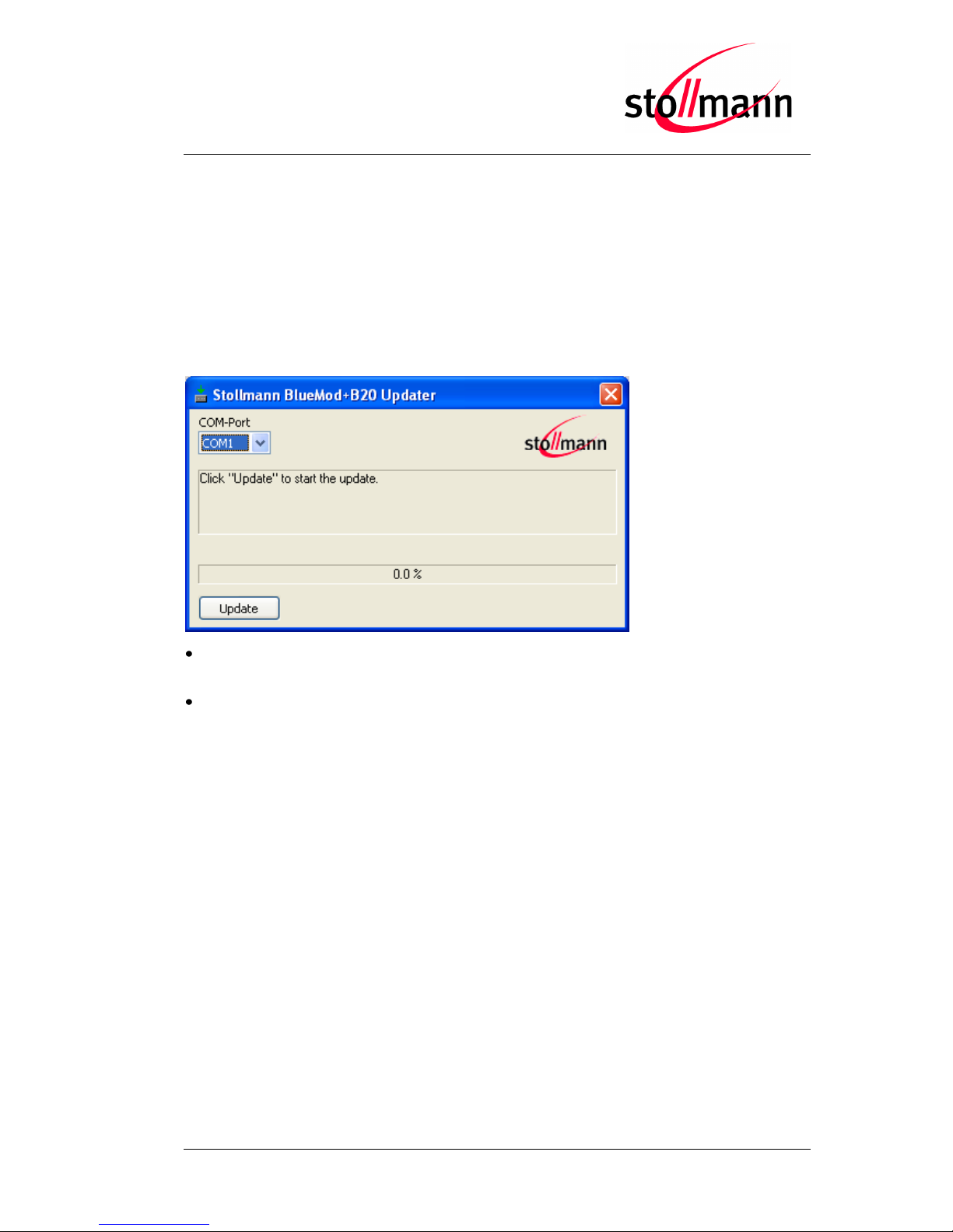
10.1.2 Stollmann BlueMod+B20 Updater
Stollmann BlueMod+B20 Updater serves as a tool for uploading a firmware file (*.dfu)
into a BlueMod+B20.
The program requires a PC with at least one free COM-Port and Windows XP or
Windows Vista as operating system.
The upload is processed via the serial port the device is attached to.
COM-Port
The COM-Port the device is attached to
Update
Starts the update procedure
Several instances of Stollmann BlueMod+B20 Updater may be started concurrently on
one PC in order to update several BlueMod+B20 in parallel.
After the successful update close the software and reset the BlueMod+B20.
Note:
All stored settings in the S registers will be lost and set to default values after the
firmware update.
Do not disconnect the device while the update is in progress, otherwise the update
will fail and has to be repeated. In case it is not possible to update the BlueMod+B20
please contact the support.
Page 35
BlueMod+B20/BT2.1
User Guide
Release r03 www.stollmann.de Page 35 of 38
10.2 Firmware Upgrade via SPI
10.2.1 Installation
The software folder on the BlueEva+B20 CD-ROM or the provided package contains
application programs for flashing new firmware and for setting specific configuration.
These application programs require a specific driver. Install the driver on your PC by
doing the steps below:
Copy all files from the “Software” folder to a directory on your hard disk
Run “InstParSpi.bat”
Run “RegPSToolocx.bat”
Reboot your PC
10.2.2 Upgrade Procedure
Connect the SPI interface of the BlueMod+B20 to the parallel port of your PC using a
SPI cable.
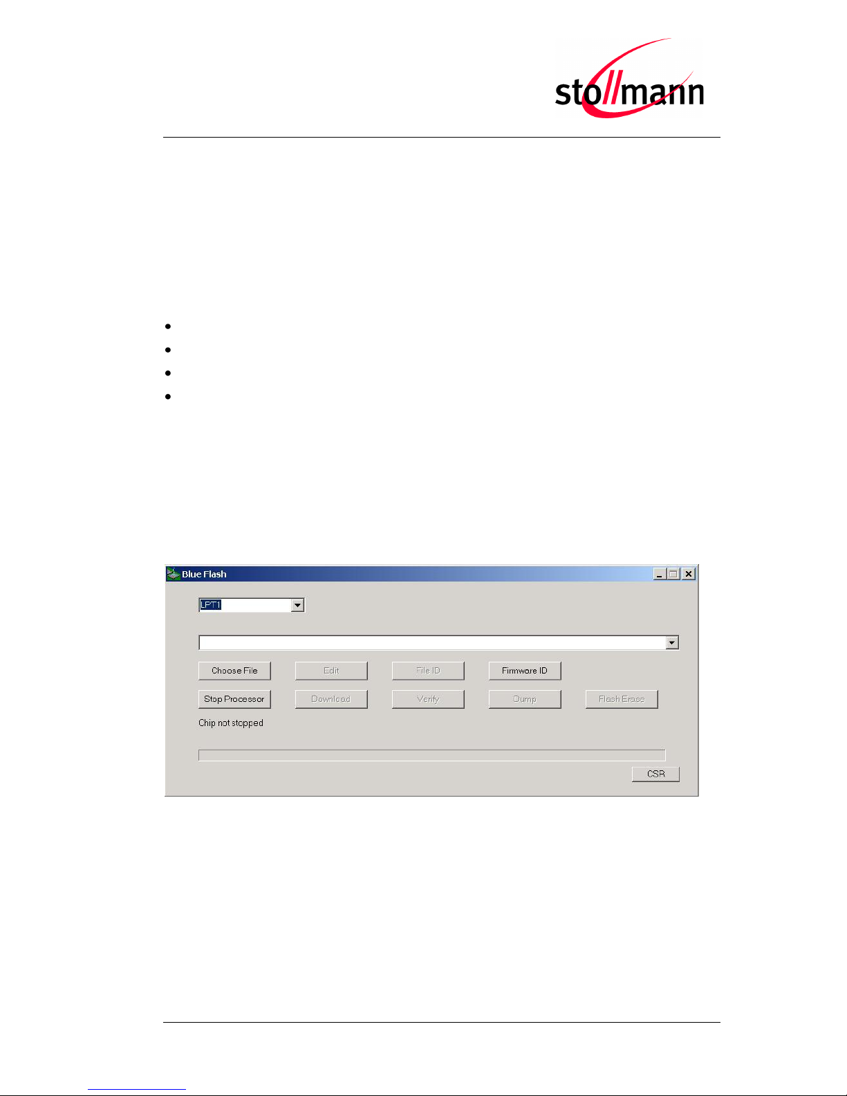
For flashing new firmware, power-on the BlueMod+B20 and start the BlueFlash
application (BlueFlash.exe).
BlueFlash application
Press the “Choose File” button and choose the firmware file you want to flash into the
BlueMod+B20. Then press the “Stop Processor” button to halt the processor, followed
by the “Download” button to start the flash procedure.
Page 36
BlueMod+B20/BT2.1
User Guide
Release r03 www.stollmann.de Page 36 of 38
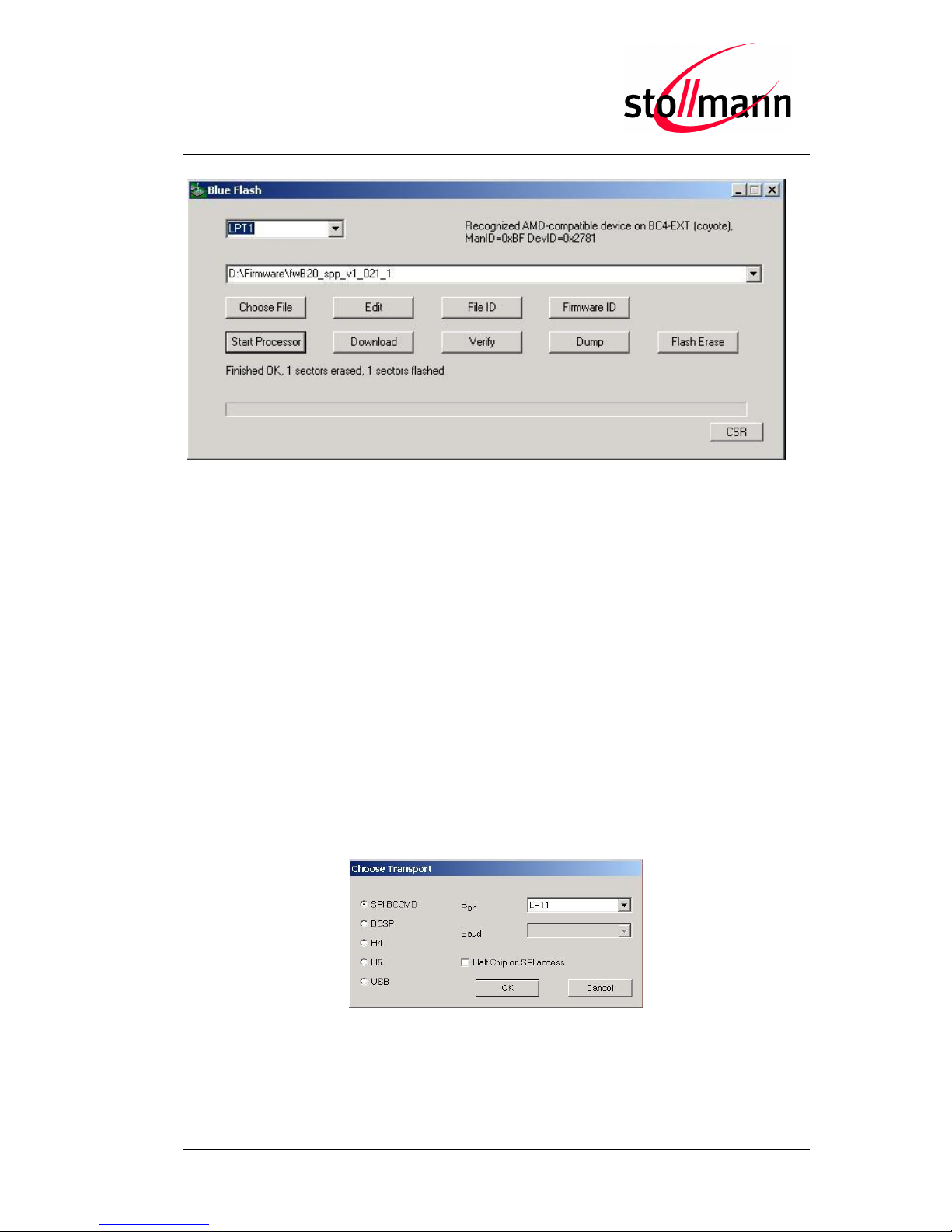
Flashing the firmware
After the flash procedure ended successfully press the “Start Processor” button to run
the new firmware.
The PS Tool application allows you to manipulate the configuration of the
BlueMod+B20 via so-called PSKeys.
Note: Change PSKeys only if you are certain of all side effects.
Normally, no changes in the PSKeys are needed to work with the BlueMod+B20. But if
you configured the BlueMod+B20 such that it is not accessible anymore, e.g. you have
configured the baud rate to 230,400 bps and the serial port of your PC only supports up
to 115,200 bps, you can use the PS Tool application to restore the factory-default
settings.
To restore the factory-default settings, power on the BlueMod+B20 and start the PS
Tool application (PSTool.exe). Select the options shown below and click OK.
Restoring PSKeys with PS Tool Step 1
Page 37
BlueMod+B20/BT2.1
User Guide
Release r03 www.stollmann.de Page 37 of 38
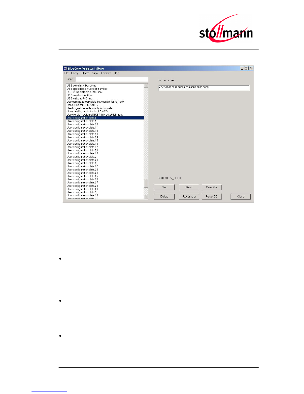
Select the PSKey “User configuration data 0” and press the “Delete” button.
Restoring PSKeys with PS Tool Step 2
After pressing the “Reset BC” button or power cycling the BlueMod+B20, it will operate
on the factory-default settings.
10.3 Troubleshooting
Update won’t start when using Stollmann BlueMod+B20 Updater
Check if the right COM-Port is selected and make sure the port is not used by other
applications running. Set the communication settings of your BlueMod+B20 to 115,200
bps, 8 data bits, no parity, 1 stop bit. Retry the update.
Update process has been interrupted by power loss / Cable replacement on
COM-Port
Redo the update by restarting the Stollmann BlueMod+B20 Updater.
Firmware won’t start after serial update, no answer on AT
Power cycle the BlueMod+B20, if the BlueMod+B20 is still not answering to AT
commands, redo the update with the Stollmann BlueMod+B20 Updater.
Page 38

BlueMod+B20/BT2.1
User Guide
Release r03 www.stollmann.de Page 38 of 38
11 History
Version
Release Date
By
Change description
r01d01
27.02.2012
hb
First release
r01
27.02.2012
ta
Review, added some corrections
r02
20.04.2012
hb,
bs,
ta
Added new chapters:
- “Out Of Range Detach”
- “Remote Configuration”
- “OBEX File Transfer”
- “Communication with Apple Devices”,
Added flow chart for “Remote Configuration”,
Added “Out Of Range Detach”, “Remote Configuration”,
“OBEX” and “Communication with Apple Devices” in
introduction
r03d01
20.06.2012
bs
hb
Added OBEX status message, OBEX data transfer flow charts,
Added new chapter 2.1.7 HID Data Flow Control,
Added chapter 9 Startup Timing,
Added note for circuit of DSR and CTS in chapter 10.1.1
Prerequisites for Device Firmware Upgrade
r03
22.06.2012
ta
Release r03
Stollmann Entwicklungs- und Vertriebs-GmbH
Mendelssohnstraße 15 D
22761 Hamburg
Germany
Phone: +49 (0)40 890 88-0
Fax: +49 (0)40 890 88-444
E-mail: [email protected]
www.stollmann.de
 Loading...