

Page 1

Operating instructions
Front loader ProfiLine
Type FS, FS-rapid emptying, FZ, FZ-L
Status: 06/2018
3468290 B58FZS 0000000078 EN 002
Page 2

Company details
Wilhelm STOLL Maschinenfabrik GmbH
PO box 1181, 38266 Lengede
Bahnhofstr. 21, 38268 Lengede
Phone: +49 (0) 53 44/20 -0
Fax: +49 (0) 53 44/20 -182
E-mail: info@stoll-germany.com
Web: www.stoll-germany.com
Spare Parts Order
Phone: +49 (0) 53 44/20 -144 and -266
Administration
Phone: +49 (0) 53 44/20 -145 and -146
Fax: +49 (0) 53 44/20 -183
E-mail: parts@stoll-germany.com
Copyright
© Wilhelm STOLL Maschinenfabrik GmbH
Reproduction of these instructions, both completely and in excerpts, is only allowed with approval from Wilhelm STOLL
Maschinenfabrik GmbH. Any infringement shall entail full compensation of damages and can be punishable by law.
The original instructions were written in the German language.
Instructions in other languages were translated from German.
Page 3

Contents
1 About this manual. . . . . . . . . . . . . . . . . . . . . . . . . . . . . . . . . . . . . . . . . . . . . . . . . . . . . 5
1.1 Documentation overview . . . . . . . . . . . . . . . . . . . . . . . . . . . . . . . . . . . . . . . . . . . . . . . . . . 5
1.2 Use and purpose of the operating instructions. . . . . . . . . . . . . . . . . . . . . . . . . . . . . . . . . . 6
1.3 Rating plate . . . . . . . . . . . . . . . . . . . . . . . . . . . . . . . . . . . . . . . . . . . . . . . . . . . . . . . . . . . . 6
1.4 Validity of the operating Instructions . . . . . . . . . . . . . . . . . . . . . . . . . . . . . . . . . . . . . . . . . 6
1.5 Storage of the documents . . . . . . . . . . . . . . . . . . . . . . . . . . . . . . . . . . . . . . . . . . . . . . . . . 6
1.6 Other applicable documents . . . . . . . . . . . . . . . . . . . . . . . . . . . . . . . . . . . . . . . . . . . . . . . 7
1.7 Design tools . . . . . . . . . . . . . . . . . . . . . . . . . . . . . . . . . . . . . . . . . . . . . . . . . . . . . . . . . . . . 7
1.8 Nomenclature of the footer. . . . . . . . . . . . . . . . . . . . . . . . . . . . . . . . . . . . . . . . . . . . . . . . . 8
2 Safety . . . . . . . . . . . . . . . . . . . . . . . . . . . . . . . . . . . . . . . . . . . . . . . . . . . . . . . . . . . . . . 9
2.1 Explanation of safety and warning notices. . . . . . . . . . . . . . . . . . . . . . . . . . . . . . . . . . . . . 9
2.2 Representation and layout of warning notices . . . . . . . . . . . . . . . . . . . . . . . . . . . . . . . . . . 9
2.3 Danger grading of warning notices . . . . . . . . . . . . . . . . . . . . . . . . . . . . . . . . . . . . . . . . . . 9
2.4 EC Conformity . . . . . . . . . . . . . . . . . . . . . . . . . . . . . . . . . . . . . . . . . . . . . . . . . . . . . . . . . . 9
2.5 Proper use . . . . . . . . . . . . . . . . . . . . . . . . . . . . . . . . . . . . . . . . . . . . . . . . . . . . . . . . . . . . 10
2.6 Operational limits . . . . . . . . . . . . . . . . . . . . . . . . . . . . . . . . . . . . . . . . . . . . . . . . . . . . . . . 10
2.7 Basic safety information . . . . . . . . . . . . . . . . . . . . . . . . . . . . . . . . . . . . . . . . . . . . . . . . . . 11
2.8 Danger zones. . . . . . . . . . . . . . . . . . . . . . . . . . . . . . . . . . . . . . . . . . . . . . . . . . . . . . . . . . 17
2.9 Safety equipment . . . . . . . . . . . . . . . . . . . . . . . . . . . . . . . . . . . . . . . . . . . . . . . . . . . . . . . 17
2.10 Adhesive safety label . . . . . . . . . . . . . . . . . . . . . . . . . . . . . . . . . . . . . . . . . . . . . . . . . . . . 18
2.11 Personnel requirements . . . . . . . . . . . . . . . . . . . . . . . . . . . . . . . . . . . . . . . . . . . . . . . . . . 23
2.12 Behaviour in case of emergency . . . . . . . . . . . . . . . . . . . . . . . . . . . . . . . . . . . . . . . . . . . 24
2.12.1 Behaviour if the tractor tips or falls over . . . . . . . . . . . . . . . . . . . . . . . . . . . . . . . . 24
2.12.2 Behaviour in case of flashovers from electrical power lines . . . . . . . . . . . . . . . . . 24
3 Structure . . . . . . . . . . . . . . . . . . . . . . . . . . . . . . . . . . . . . . . . . . . . . . . . . . . . . . . . . . . 25
3.1 Structure of FS front loaders . . . . . . . . . . . . . . . . . . . . . . . . . . . . . . . . . . . . . . . . . . . . . . 25
3.2 Structure of FZ front loaders . . . . . . . . . . . . . . . . . . . . . . . . . . . . . . . . . . . . . . . . . . . . . . 27
3.3 Equipment variations . . . . . . . . . . . . . . . . . . . . . . . . . . . . . . . . . . . . . . . . . . . . . . . . . . . . 29
3.4 Attaching it to the tractor . . . . . . . . . . . . . . . . . . . . . . . . . . . . . . . . . . . . . . . . . . . . . . . . . 30
3.5 Change frame . . . . . . . . . . . . . . . . . . . . . . . . . . . . . . . . . . . . . . . . . . . . . . . . . . . . . . . . . 31
3.5.1 Euro change frame . . . . . . . . . . . . . . . . . . . . . . . . . . . . . . . . . . . . . . . . . . . . . . . . 31
3.5.2 SMS change frame . . . . . . . . . . . . . . . . . . . . . . . . . . . . . . . . . . . . . . . . . . . . . . . . 32
3.5.3 Euro-SMS Combi change frame . . . . . . . . . . . . . . . . . . . . . . . . . . . . . . . . . . . . . . 32
3.5.4 Euro-Alö3 Combi change frame . . . . . . . . . . . . . . . . . . . . . . . . . . . . . . . . . . . . . . 33
3.5.5 Euro-FR Combi change frame . . . . . . . . . . . . . . . . . . . . . . . . . . . . . . . . . . . . . . . 33
3.5.6 Skid-steer change frame . . . . . . . . . . . . . . . . . . . . . . . . . . . . . . . . . . . . . . . . . . . . 34
3.5.7 Reinforced Euro change frame (FZ 100) . . . . . . . . . . . . . . . . . . . . . . . . . . . . . . . 34
3.6 Hydraulic lines . . . . . . . . . . . . . . . . . . . . . . . . . . . . . . . . . . . . . . . . . . . . . . . . . . . . . . . . . 35
3.7 Hydraulic couplings . . . . . . . . . . . . . . . . . . . . . . . . . . . . . . . . . . . . . . . . . . . . . . . . . . . . . 35
3.7.1 Plug-in couplings. . . . . . . . . . . . . . . . . . . . . . . . . . . . . . . . . . . . . . . . . . . . . . . . . . 35
3.7.2 Multiple coupling Hydro-Fix. . . . . . . . . . . . . . . . . . . . . . . . . . . . . . . . . . . . . . . . . . 36
B58FZS 0000000078 EN 002 2
Page 4

4 Functions . . . . . . . . . . . . . . . . . . . . . . . . . . . . . . . . . . . . . . . . . . . . . . . . . . . . . . . . . . . 37
4.1 Implement locking mechanism . . . . . . . . . . . . . . . . . . . . . . . . . . . . . . . . . . . . . . . . . . . . 37
4.1.1 Mechanical implement locking mechanism . . . . . . . . . . . . . . . . . . . . . . . . . . . . . 37
4.1.2 Hydraulic implement locking mechanism – Hydro-Lock . . . . . . . . . . . . . . . . . . . . 39
4.2 Basic functions. . . . . . . . . . . . . . . . . . . . . . . . . . . . . . . . . . . . . . . . . . . . . . . . . . . . . . . . . 40
4.3 Float position . . . . . . . . . . . . . . . . . . . . . . . . . . . . . . . . . . . . . . . . . . . . . . . . . . . . . . . . . . 43
4.3.1 Lifting arm float position . . . . . . . . . . . . . . . . . . . . . . . . . . . . . . . . . . . . . . . . . . . . 44
4.3.2 Implement float position . . . . . . . . . . . . . . . . . . . . . . . . . . . . . . . . . . . . . . . . . . . . 44
4.4 Indicator for implement position. . . . . . . . . . . . . . . . . . . . . . . . . . . . . . . . . . . . . . . . . . . . 45
4.5 Parallel motion (FZ, FZ-L) . . . . . . . . . . . . . . . . . . . . . . . . . . . . . . . . . . . . . . . . . . . . . . . . 45
4.6 Rapid traverse emptying (FS) and quick emptying (FZ-L). . . . . . . . . . . . . . . . . . . . . . . . 46
4.7 Return-To-Level (FZ-L) . . . . . . . . . . . . . . . . . . . . . . . . . . . . . . . . . . . . . . . . . . . . . . . . . . 47
4.8 Anti-lowering guard . . . . . . . . . . . . . . . . . . . . . . . . . . . . . . . . . . . . . . . . . . . . . . . . . . . . . 48
4.9 Additional functions . . . . . . . . . . . . . . . . . . . . . . . . . . . . . . . . . . . . . . . . . . . . . . . . . . . . . 49
4.9.1 Additional control circuits . . . . . . . . . . . . . . . . . . . . . . . . . . . . . . . . . . . . . . . . . . . 49
4.9.2 Comfort Drive . . . . . . . . . . . . . . . . . . . . . . . . . . . . . . . . . . . . . . . . . . . . . . . . . . . . 50
4.9.3 Lowering throttle . . . . . . . . . . . . . . . . . . . . . . . . . . . . . . . . . . . . . . . . . . . . . . . . . . 52
4.9.4 Camera system . . . . . . . . . . . . . . . . . . . . . . . . . . . . . . . . . . . . . . . . . . . . . . . . . . 52
5 Start-up . . . . . . . . . . . . . . . . . . . . . . . . . . . . . . . . . . . . . . . . . . . . . . . . . . . . . . . . . . .. 53
5.1 Initial operation . . . . . . . . . . . . . . . . . . . . . . . . . . . . . . . . . . . . . . . . . . . . . . . . . . . . . . . . 53
5.2 Check before each start-up . . . . . . . . . . . . . . . . . . . . . . . . . . . . . . . . . . . . . . . . . . . . . . . 53
5.3 Preparations . . . . . . . . . . . . . . . . . . . . . . . . . . . . . . . . . . . . . . . . . . . . . . . . . . . . . . . . . . 54
5.3.1 Preparations on the tractor . . . . . . . . . . . . . . . . . . . . . . . . . . . . . . . . . . . . . . . . . . 54
5.3.2 Ballasting . . . . . . . . . . . . . . . . . . . . . . . . . . . . . . . . . . . . . . . . . . . . . . . . . . . . . . . 55
5.4 Adjusting the front loader locking mechanism . . . . . . . . . . . . . . . . . . . . . . . . . . . . . . . . . 57
5.4.1 Adjusting the FS and FZ 8 to 50 front loader locking mechanism . . . . . . . . . . . . 57
5.4.2 Adjusting the "Double locking mechanism" FZ 50 to 100 front loader locking
mechanism . . . . . . . . . . . . . . . . . . . . . . . . . . . . . . . . . . . . . . . . . . . . . . . . . . . . . . 59
5.5 Mounting the front loader. . . . . . . . . . . . . . . . . . . . . . . . . . . . . . . . . . . . . . . . . . . . . . . . . 61
5.6 Aligning the front loader for mounting . . . . . . . . . . . . . . . . . . . . . . . . . . . . . . . . . . . . . . . 63
6 Operation . . . . . . . . . . . . . . . . . . . . . . . . . . . . . . . . . . . . . . . . . . . . . . . . . . . . . . . . . . . 64
6.1 Operating elements . . . . . . . . . . . . . . . . . . . . . . . . . . . . . . . . . . . . . . . . . . . . . . . . . . . . . 64
6.1.1 Basic controls with levers . . . . . . . . . . . . . . . . . . . . . . . . . . . . . . . . . . . . . . . . . . . 64
6.1.2 Tractor's own operating lever . . . . . . . . . . . . . . . . . . . . . . . . . . . . . . . . . . . . . . . . 66
6.1.3 STOLL Base Control . . . . . . . . . . . . . . . . . . . . . . . . . . . . . . . . . . . . . . . . . . . . . . 67
6.1.4 STOLL Pro Control . . . . . . . . . . . . . . . . . . . . . . . . . . . . . . . . . . . . . . . . . . . . . . . . 69
6.1.5 STOLL Trac Control . . . . . . . . . . . . . . . . . . . . . . . . . . . . . . . . . . . . . . . . . . . . . . . 72
6.1.6 Switch/changeover switch . . . . . . . . . . . . . . . . . . . . . . . . . . . . . . . . . . . . . . . . . . 73
6.1.7 Comfort-Hydraulic. . . . . . . . . . . . . . . . . . . . . . . . . . . . . . . . . . . . . . . . . . . . . . . . . 74
6.2 Operating the parking supports . . . . . . . . . . . . . . . . . . . . . . . . . . . . . . . . . . . . . . . . . . . . 75
6.3 Operating the hydraulic couplings . . . . . . . . . . . . . . . . . . . . . . . . . . . . . . . . . . . . . . . . . . 76
6.3.1 Operating the plug-in coupling . . . . . . . . . . . . . . . . . . . . . . . . . . . . . . . . . . . . . . . 76
6.3.2 Operating Hydro-Fix . . . . . . . . . . . . . . . . . . . . . . . . . . . . . . . . . . . . . . . . . . . . . . . 77
6.4 Operating the implement locking mechanism . . . . . . . . . . . . . . . . . . . . . . . . . . . . . . . . . 78
6.4.1 Operating the mechanical implement locking mechanism on Euro, SMS and
Combi change frames . . . . . . . . . . . . . . . . . . . . . . . . . . . . . . . . . . . . . . . . . . . . . 78
6.4.2 Operating the mechanical implement locking mechanism on skid-steer change
6.4.3 Operating the hydraulic implement locking mechanism . . . . . . . . . . . . . . . . . . . . 81
6.5 Picking up and putting down the implement . . . . . . . . . . . . . . . . . . . . . . . . . . . . . . . . . . 82
3 B58FZS 0000000078 EN 002
frames . . . . . . . . . . . . . . . . . . . . . . . . . . . . . . . . . . . . . . . . . . . . . . . . . . . . . . . . . 80
Page 5

6.5.1 Picking up implements with mechanical implement locking mechanism on Euro,
SMS and Combi change frames . . . . . . . . . . . . . . . . . . . . . . . . . . . . . . . . . . . . . . 83
6.5.2 Picking up implements with mechanical implement locking mechanism on skid-
steer change frames . . . . . . . . . . . . . . . . . . . . . . . . . . . . . . . . . . . . . . . . . . . . . . . 85
6.5.3 Picking up implements with a hydraulic implement locking mechanism. . . . . . . . 87
6.5.4 Putting down the implement . . . . . . . . . . . . . . . . . . . . . . . . . . . . . . . . . . . . . . . . . 88
6.6 Levelling in reverse . . . . . . . . . . . . . . . . . . . . . . . . . . . . . . . . . . . . . . . . . . . . . . . . . . . . . 89
6.7 Driving on roads . . . . . . . . . . . . . . . . . . . . . . . . . . . . . . . . . . . . . . . . . . . . . . . . . . . . . . . . 90
6.7.1 Activating and deactivating the road operation lock . . . . . . . . . . . . . . . . . . . . . . . 91
6.7.2 Passing through low clearances . . . . . . . . . . . . . . . . . . . . . . . . . . . . . . . . . . . . . . 91
6.8 Parking the tractor with the front loader . . . . . . . . . . . . . . . . . . . . . . . . . . . . . . . . . . . . . . 92
7 Troubleshooting . . . . . . . . . . . . . . . . . . . . . . . . . . . . . . . . . . . . . . . . . . . . . . . . . . . . . 93
8 Servicing. . . . . . . . . . . . . . . . . . . . . . . . . . . . . . . . . . . . . . . . . . . . . . . . . . . . . . . . . . . 96
8.1 Cleaning and care . . . . . . . . . . . . . . . . . . . . . . . . . . . . . . . . . . . . . . . . . . . . . . . . . . . . . . 97
8.1.1 Lubrication points . . . . . . . . . . . . . . . . . . . . . . . . . . . . . . . . . . . . . . . . . . . . . . . . . 97
8.1.2 Lubrication schedule . . . . . . . . . . . . . . . . . . . . . . . . . . . . . . . . . . . . . . . . . . . . . . . 99
8.2 Service . . . . . . . . . . . . . . . . . . . . . . . . . . . . . . . . . . . . . . . . . . . . . . . . . . . . . . . . . . . . . . 100
8.2.1 Service schedule. . . . . . . . . . . . . . . . . . . . . . . . . . . . . . . . . . . . . . . . . . . . . . . . . 100
8.2.2 Service instructions for front loader mountings . . . . . . . . . . . . . . . . . . . . . . . . . . 101
8.2.3 Service instructions for front loader locking mechanism . . . . . . . . . . . . . . . . . . . 102
8.2.4 Service instructions for Comfort Drive . . . . . . . . . . . . . . . . . . . . . . . . . . . . . . . . 103
8.2.5 Service instructions for the hydraulic lines . . . . . . . . . . . . . . . . . . . . . . . . . . . . . 103
8.2.6 Service instructions for oil changes . . . . . . . . . . . . . . . . . . . . . . . . . . . . . . . . . . 104
8.3 Repairs. . . . . . . . . . . . . . . . . . . . . . . . . . . . . . . . . . . . . . . . . . . . . . . . . . . . . . . . . . . . . . 104
9 Decommissioning . . . . . . . . . . . . . . . . . . . . . . . . . . . . . . . . . . . . . . . . . . . . . . . . . . . 105
9.1 Temporary decommissioning . . . . . . . . . . . . . . . . . . . . . . . . . . . . . . . . . . . . . . . . . . . . . 105
9.2 Recommissioning. . . . . . . . . . . . . . . . . . . . . . . . . . . . . . . . . . . . . . . . . . . . . . . . . . . . . . 106
9.3 Final decommissioning and disposal . . . . . . . . . . . . . . . . . . . . . . . . . . . . . . . . . . . . . . . 107
10 Spare parts and customer service . . . . . . . . . . . . . . . . . . . . . . . . . . . . . . . . . . . . . . 108
10.1 Spare parts. . . . . . . . . . . . . . . . . . . . . . . . . . . . . . . . . . . . . . . . . . . . . . . . . . . . . . . . . . . 108
10.2 Customer service . . . . . . . . . . . . . . . . . . . . . . . . . . . . . . . . . . . . . . . . . . . . . . . . . . . . . . 108
11 Technical Specifications . . . . . . . . . . . . . . . . . . . . . . . . . . . . . . . . . . . . . . . . . . . . . . 109
11.1 Dimensions and weights . . . . . . . . . . . . . . . . . . . . . . . . . . . . . . . . . . . . . . . . . . . . . . . . 109
11.2 Noise emissions . . . . . . . . . . . . . . . . . . . . . . . . . . . . . . . . . . . . . . . . . . . . . . . . . . . . . . . 109
11.3 Tightening torque for screws . . . . . . . . . . . . . . . . . . . . . . . . . . . . . . . . . . . . . . . . . . . . . 110
11.4 Hydraulic diagram . . . . . . . . . . . . . . . . . . . . . . . . . . . . . . . . . . . . . . . . . . . . . . . . . . . . . 111
11.4.1 Hydraulic diagram FS and FS-rapid emptying . . . . . . . . . . . . . . . . . . . . . . . . . . 111
11.4.2 Hydraulics diagram FZ and FZ-L . . . . . . . . . . . . . . . . . . . . . . . . . . . . . . . . . . . . 112
11.5 Electric circuit diagram . . . . . . . . . . . . . . . . . . . . . . . . . . . . . . . . . . . . . . . . . . . . . . . . . . 113
11.6 Arrangement of the hydraulic valves for additional functions. . . . . . . . . . . . . . . . . . . . . 114
12 Declaration of Conformity . . . . . . . . . . . . . . . . . . . . . . . . . . . . . . . . . . . . . . . . . . . . . 115
Index. . . . . . . . . . . . . . . . . . . . . . . . . . . . . . . . . . . . . . . . . . . . . . . . . . . . . . . . . . . . . 117
B58FZS 0000000078 EN 002 4
Page 6

1 About this manual
1.1 Documentation overview
There are various instructions and technical documentation for the front loader, mounting kit and
accessories. Most documents are available in multiple languages.
If a set of instructions is missing or required in a different language:
Order the instructions through a dealer.
Download instructions free of charge from the Internet at www.stoll-germany.com.
Installation instructions
The installation of the mounting kit as well as the hydraulic and electric equipment may only be
performed by an authorised specialised workshop.
The installation instructions describe how to install the front loader mounting kit and the hydraulic and
electrical equipment up to the initial start-up of the front loader. They are intended for the specialist
workshop.
The installation instructions have been specially compiled for this tractor model. They do not contain
any information that is already included in the operating instructions.
The installation instructions contain information on spare parts for the tractor-specific mounting parts
and equipment.
ABOUT THIS MANUAL
Operating instructions of the front loader
These operating instructions describe the safe use of the front loader from the initial operation to its
disposal. They are intended for the operator and the user of the front loader.
The operating instructions are compiled specifically for the front loader series, they can therefore only
take tractor-specific equipment into account to a limited extent.
Spare parts list
The spare parts list of the front loader lists all the information required for ordering spare parts, the front
loader series and their options. Special adaptations for the tractor are not taken into account.
In addition, spare parts lists are available for front loader implements.
Operating instructions for front loader implements
The operating instructions describe the implements available for the front loader series.
Other documents
In addition to the above instruction manuals, there may be installation and operating instructions as well
as other Technical Information that deal with special additional equipment and extensions, which are
not included in the other documentation.
When you pass on the front loader or the tractor with a front loader attached, please also hand
over all the relevant documents. The next owner needs the information.
5 B58FZS 0000000078 EN 002
Page 7

ABOUT THIS MANUAL
11
66
55
44
33
77
22
Wilhelm Stoll Maschinenfabrik GmbH
Product Type XXXXXXXXXXXXXXXXXXXX
Serial-No. XXXXXXX
Month / Year XX XXXX
Weight XXXX kg
max. Hydraulic Pressure XXXX bar
Made in Germany Bahnhofstraße 21 · 38268 Lengede · Germany
11
66
55
44
33
77
22
Wilhelm Stoll Maschinenfabrik GmbH
Product Type XXXXXXXXXXXXXXXXXXXX
Serial-No. XXXXXXX
Month / Year XX XXXX
Weight XXXX kg
Max. Hydraulic Pressure XXXX bar
Made in Germany Bahnhofstraße 21 · 38268 Lengede · Germany
11
55
33
44
22
B029B029
1.2 Use and purpose of the operating instructions
The present operating instructions contain important information on the safe operation and for faultless,
proper and economical operation of front loaders from Wilhelm STOLL Maschinenfabrik GmbH. It is
intended for the operator and user of the front loader and should help to prevent risks, damage and
downtimes as well as ensure and increase the service life of the front loader.
Before start-up of the front loader, the operating instructions must be read and understood.
For better readability, Wilhelm STOLL Maschinenfabrik GmbH will be called "STOLL" in the following.
The operating instructions are compiled specifically for the front loader series, they can therefore only
take tractor-specific equipment into account to a limited extent.
1.3 Rating plate
The front loader is identified with a that is located on the inside of the left bar at the rear or on the cross
tube of the front loader.
Fig. 1 Rating plate on the front loader
Legend
1 Type of front loader (e.g. ProfiLine front loader FZ 20, Solid 38-20)
2 Serial number
3 Year of manufacture
4 Weight
5 Permissible hydraulic pressure
1.4 Validity of the operating Instructions
The operating instructions are valid only for the STOLL front loader ProfiLine, called "front loader" in the
following or "FS" or "FZ" as the special versions. The front loader type can be found on the rating plate.
The operating instructions covers all of the components and functions of the model.
1.5 Storage of the documents
The operating instructions are a part of the machine. The entire documentation, consisting of these
operating instructions as well as all other additional instructions supplied, must always be kept
accessible, safe and dry on or in the vehicle. When lending or selling the front loader, the entire
documentation must also be handed over.
B58FZS 0000000078 EN 002 6
Page 8

1.6 Other applicable documents
In conjunction with these operating instructions, the following additional documents also apply:
Operating instructions of the tractor
Operating instructions for the respective implements
Installation instructions for the respective mounting kit and front loader additional equipment
When handling the front loader and for all service work, please also observe:
The recognised technical regulations for safe and professional work,
The legal regulations for accident prevention,
The legal regulations for health and environmental protection,
The national regulations that apply in the country of the operator / user of the front loader,
The specifications that are relevant for the status of the technology,
The road traffic regulations.
1.7 Design tools
The operating instructions contain the following different symbols and markings in the text:
ABOUT THIS MANUAL
Warning symbol that is used for warning notices and is graduated based on the danger
(see 2 Safety)
Additional information and tips
List points
Requirement for a sequence of actions
Required tools
(1) Numbered action step
Result of an action or sequence of actions
Unnumbered action step
7 B58FZS 0000000078 EN 002
Page 9

ABOUT THIS MANUAL
11 22
Moreover, stylised drawings are used. For better understanding, some of the figures are exemplary,
simplified or with dismounted parts for better representation and explanation.
Please observe the following:
Dismounting is not always absolutely required for the respective description.
No different equipment variations are shown in the figures, unless otherwise specified.
The associated descriptive text always applies to the figures.
The following representation rules and elements apply:
Representation Meaning
Elements represented in yellow highlight the
components for the respective operating situation.
Item numbers designate assemblies or
components. In each figure, there is always an
explanatory legend for the item numbers.
Magnifying glasses serve to focus on individual
parts and details.
Arrows indicate a direction of movement or action
to be performed.
1.8 Nomenclature of the footer
The footer consists of the following parameters:
1234567 A12XYZ 0000001234 DE 123
Fig. 2 Nomenclature of the footer
Legend
1 Document number (order number)
2 Type of instructions
3 Internal system number
4 Language identifier
5Version
2211 33 44 55
B58FZS 0000000078 EN 002 8
Page 10

2 Safety
2.1 Explanation of safety and warning notices
The basic safety information comprises instructions that always apply for safe operation or to maintain
the safe condition of the front loader.
The action-related warning notices warn against residual dangers and are placed in front of dangerous
action sequences.
2.2 Representation and layout of warning notices
Warning notices are action-related and are designed according to the following principle:
⚠ DANGER
Type and source of danger!
Explanation of the type and source of danger.
Measures to prevent the danger.
SAFETY
2.3 Danger grading of warning notices
Warning notices are graded according to their level of danger and are represented as follows with the
corresponding signal words and warning symbols:
⚠ DANGER
Immediate lethal danger or serious injuries.
⚠ WARNING
Possible lethal danger or serious injuries.
⚠ CAUTION
Possible slight injuries.
NOTICE
Damage to the implement or the surroundings.
2.4 EC Conformity
STOLL front loaders comply with Machine Directive 2006/42/EC.
9 B58FZS 0000000078 EN 002
Page 11

SAFETY
2.5 Proper use
The ProfiLine front loader is a mounted implement for agricultural and forestry tractors and is designed
and intended solely for:
Mounting on tractors with the front loader mounting kit approved by STOLL (see 1.1 Documentation
overview),
Use with work implements specified by STOLL, which are suitable for the respective loading work
(see 6.5 Picking up and putting down the implement and operating instructions for the implement),
Use and operation within the defined limits (see 11 Technical specifications),
Control from the driver's seat.
The front loader may only be operated when it is in perfect condition. If faults impair safety, these must
be promptly repaired by an authorised specialist workshop.
The front loader must not be used in work processes and with implements that require the presence of
people close to the load when the front loader is in the raised position! This kind of work is only permitted
if the front loader is equipped with an anti-lowering guard (4.8 Anti-lowering guard).
The front loader and its implements must not be operated simultaneously with other hydraulic
equipment on the tractor.
Proper use also includes reading and observing the operating instructions, the associated additional
instructions, the other applicable documents as well as the safety information. To ensure operational
safety, prescribed maintenance work as well as intervals and conditions for care and service must also
be observed. Any use other or beyond those described in the manual is considered as improper use.
Foreseeable misuse
Avoid the following:
Exceeding of the permissible axle load and the permissible total weight of the tractor
Use outside of the conditions and prerequisites that are specified in the technical manuals and
documents
Transport of persons
Transport of loads that are not intended for use with front loaders
Transport of loads in road traffic
Transport of unsecured loads (e.g. stone pallets)
2.6 Operational limits
The following operating conditions and requirements on the operational environment must be
observed:
If applicable, temperature range for proper operation of the tractor (see operating instructions of the
tractor)
Sufficient load capacity of the tires and the front axle of the tractor
B58FZS 0000000078 EN 002 10
Page 12

2.7 Basic safety information
The basic safety information comprises all safety measures grouped by theme and is applicable at all
times. In addition, the information is presented as warning notices at the correspoding positions in these
operating instructions.
Basic dangers
Mortal danger exists when persons are lifted or carried with the front loader. The front
loader is not equipped with the necessary safety equipment to be used as a work cage.
It is forbidden to lift or transport people with the front loader.
Mechanical dangers
There is a risk of crushing and impact of the upper and lower limbs due to projecting or
protruding frame parts and moving components of the machine.
Personnel must be instructed in the proper use of the machine and in the location
and types of danger.
Instruct persons to exit the danger and movement areas of the machine.
SAFETY
Wear suitable protective gear, if necessary, when performing service tasks.
There is a lethal risk of crushing and injury due to accidental movements of the tractor,
the front loader, and the implements.
Instruct unauthorised persons to exit the danger and action area of the machine.
Assistance from a second person for loading activities should only be allowed when
the front loader is lowered, provided that an anti-lowering guard is not installed.
For loading work as well as when mounting and dismounting the front loader,
ensure that the tractor is standing on level and solid ground.
The front loader may only be operated from the driver's seat of the tractor.
Operating elements outside of the tractor must not affect the front loader! In
particular, the operating elements of the front linkage must not affect the front
loader!
The front loader must only be operated by one person.
There is a lethal risk of injury due to exceeding of the maximum permissible load or with
improper use of the front loader resulting in breaking of the front loader or its
components.
Observe the load limits specified in the technical data.
When levelling or pushing snow, do not drive faster than 10 km/h.
Work only with mounted and locked implement.
Observe the load capacity of the tyres and the front axle of the tractor.
11 B58FZS 0000000078 EN 002
Page 13

SAFETY
0 Bar
Hydraulic dangers
There is a risk of injury due to escaping hydraulic fluids under high pressure.
Observe the safety stickers on the machine.
Check the hydraulic couplings and lines for leaks before uncoupling.
On tractors without a closed driver’s cab, mount tubes with splash guards.
There is a risk of crushing when machine parts move uncontrollably due to entrapped air
in the hydraulic system.
Before performing any work on the hydraulic system, depressurize the system.
Clean the hydraulic couplings and lines before coupling.
Change the hydraulic fluid regularly according to the service schedule.
Electrical dangers
There is lethal danger due to power surges when touching live machine parts, e.g. due
to short circuits in the on-board network of the tractor.
Installation and service tasks on the electrical system should only be performed by
Observe the operating instructions of the tractor.
There is lethal danger due to collision of the raised front loader with high-voltage lines.
Do not raise the front loader higher than 4 m when driving on roads.
Keep a safe distance away from electrical lines.
If you do not know the rated voltage, stay at least 4 m away from electrical lines.
There is lethal danger during excavation work due to collision with cables buried in the
ground.
Before performing excavation work, ensure that there are no cables in the ground.
an electrician.
Danger due to emissions
With long-lasting normal operation of the machine, hearing damage can be caused by
the noise level of the tractor and the hydraulic system.
Always wear personal hearing protection.
Observe special regulations for road operation and for operating machines in open
spaces.
B58FZS 0000000078 EN 002 12
Page 14

Dangers during packaging and transport
There is a risk of injury due to crushing, impacts or pinching if the front loader tips over or
falls from the lifting gear.
During all preparatory work, always ensure a secure stand of the machine.
Assisting persons must be instructed to exit the immediate danger area under the
front loader.
There is a risk of accidents during transport of the front loader if it is not correctly loaded
and secured.
The front loader must be correctly secured and transported.
SAFETY
Dangers during assembly for initial operation
There is a risk of injury when lifting and handling heavy machine parts as well as bulky
components of the front loader.
Heavy and bulky machine parts may only be lifted with the assistance of a second
person.
Avoid back injuries by lifting correctly.
Dangers when mounting and dismounting the front loader
There is a risk of injury when the front loader tips over during mounting or dismounting or
when the parked front loader tips over due to a lack of stability.
Ensure the stability of the front loader and the tractor.
Observe the instructions and sequence in these operating instructions for proper
mounting and dismounting of the front loader.
Check the proper locking of the front loader.
There is a risk of crushing of limbs when operating the parking supports to park the front
loader, especially on uneven ground.
Observe the instructions and sequence in these operating instructions for proper
operation of the parking supports.
13 B58FZS 0000000078 EN 002
Page 15

SAFETY
Dangers when picking up and putting down implements
There is a risk of serious injury and lethal danger due to implements falling down or
uncontrolled lowering of the front loader when unsuitable implements are used or if the
used implements are overloaded.
Check that the implements are suitable before use.
Check that the implement is locked correctly by repeatedly putting the implement
down on the ground.
Perform a visual check on the locking device.
Only perform the hydraulic locking of the implement up to a height of 1.5 m.
Check the proper functioning of the implements one time without load before
beginning work.
Dangers during loading work
There is a risk of serious injury and mortal danger when loading and transporting loads,
if the front loader is operated from one side, the load is raised too far over the driver's
seat or if unsuitable implements are used.
If not equipped, check for retrofitting a cab and/or a FOPS (falling objects protection
structure) / ROPS (roll-over protection structure) within the framework of work
safety regulations.
If there is no cab or safety equipment, never lift loads over the driver's seat.
Only use suitable implements, which prevent e.g. rolling back and falling on the
driver's seat.
B58FZS 0000000078 EN 002 14
Page 16

Dangers when operating the front loader
There is a risk of serious injury or lethal danger due to tipping of the tractor when working
on slopes, when going around bends, when the load on the rear axle is too low, and when
driving into the bulk to be lifted at a skewed angle.
The risk increases when the front loaders are raised up high because of the higher centre
of gravity.
Drive carefully when working on slopes. Never travel with a raised load across a
≥ 20%
10 km/h
slope.
Ensure that the ground is level enough.
When driving in curves, reduce the speed and lower the load.
Never start driving abruptly with the front loader raised high and fully loaded.
Observe and comply with the maximum load of the tractor.
Always use sufficient counterweights at the rear of the tractor.
In case of instability or tipping, lower the front loader and remain in the driver's cab.
Drive towards the load in a straight line and do not steer while driving into the load.
Use the safety belts.
SAFETY
Connect the brake pedals.
Switch off the front axle suspension.
On tractors with adjustable track width: set the maximum possible track width.
When driving on roads, there is a risk of serious injury and lethal danger for the operator
as well as for other road users if the tractor and the front loader a re no t correctly p repared
and operated for road traffic.
Only drive on roads without a load.
Before driving on roads, switch off the hydraulic system and lock it.
Raise the front loader.
15 B58FZS 0000000078 EN 002
Page 17

SAFETY
Dangers due to falling loads
There is mortal danger due to raised loads falling down on the driver's seat. There is a
particularly high risk when lifting pallets or bales above the driver's cab and when working
on slopes. Even the standard protection systems (roll-over protection structure ROPS,
falling objects protective structures FOPS) do not provide fully adequate protection.
When working on slopes, reduce the implement filling and lower the load.
Check the inclination of the implement. Do not scoop too far with the implement.
Use implements that are designed such that they prevent loads from falling onto the
driver's seat.
Only use the appropriate implements when loading piece goods (e.g. bale grabber
for bales or pallet fork for pallets).
Lift pallets or bales one at a time. Never stack several loads on top of each other,
since the top load could fall down on the driver's seat.
Compensate for the increased angle on front loaders without parallel motion when
lifting by “dumping” with the implement.
Do not operate the front loader without parallel motion while driving in reverse.
On tractors without a cab or 4-post roll-over protection structure, do not lift large
load items, in particular bales, any higher than the pivot point of the lifting arm.
Watch the load as you are lifting. Do not lift the load when reversing.
Dangers during maintenance
Maintenance work carried out incorrectly (care and cleaning, service, repairs) impair the
safety of the front loader.
Check the front loader regularly for defects.
Check mounting parts (brackets) regularly for damage (cracks).
Care and cleaning work must be carried out correctly.
Only have repair work performed by authorised qualified personnel.
B58FZS 0000000078 EN 002 16
Page 18

2.8 Danger zones
B081
11
22
33
On and around the front loader, there are the following areas with increased risk to safety of the operator
or safety of other persons:
Fig. 3 Top view (from above)
Legend
1 Work area (yellow)
2 Outer danger zones (hatched in orange)
3 Inner danger zones (red)
SAFETY
Danger zone Description Danger
Work area Overall possible movement area of the tractor incl.
Outer danger zone Overall field of action of the tractor and front loader
Inner danger zone Area on and around the tractor and front loader,
Observe the danger zones and instruct unauthorised persons out of these areas.
2.9 Safety equipment
Depending on the equipment, the front loader has the following protective and safety equipment:
the front loader during loading work.
as well as the area in which the tractor or front
loader could tip over in case of accident:
On the sides (left and right): height of the
tractor with the front loader raised as far as it
goes (incl. implement)
Front and rear: half the height of the tractor
with the front loader raised as far as it goes
(incl. implement)
especially between the wheels of the tractor,
directly in front of and behind the tractor as well as
on and under the front loader.
Standing in the working area represents a risk.
When the tractor tips over or when loads fall
down, people can be seriously injured.
Persons can be pinched in between the
wheels of the tractor.
Persons can be overseen by the tractor driver
and run over.
Moving machine parts can move
uncontrollably and thereby crush and injure
people.
Protective/safety equipment Function
Safety stickers Safety stickers warns against hazards at danger points (see 2.10 Adhesive safety
label).
Anti-lowering guard The anti-lowering guard protects against accidental lowering of the front loader during
work that requires another person in the working or danger zone of the front loader
(see 4.8 Anti-lowering guard).
17 B58FZS 0000000078 EN 002
Page 19

SAFETY
1010
22
1
133
3
3
4
4
5
5
6
6
7
7
8
8
8
8
12
12
9
9
11
11
B06S
1313
1414 1414
2.10 Adhesive safety label
Safety stickers warn of hazards at danger points and are an important part of the safety equipment of
the front loader.
Clean safety stickers if they are soiled.
Replace damaged or illegible safety stickers (see 10.1 Spare parts).
If necessary, equip new spare parts with the corresponding safety stickers.
Position of the safety sticker on the front loader
Fig. 4 Front loader FZ (exemplary figure)
Legend
1 Safety instructions on the left pillar
2 Safety instructions in the tractor driver's cab
3 Safety instructions on the left and right lifting arm
4 Safety instructions on the right parking support
5 Safety instructions on the left parking support
6 Mounting and dismounting instructions for the front loader on the right pillar
7 Information on the operation of Comfort-Drive on the cross tube
8 Information for crane transport above, below or next to the hole for the hook
(on the deviation triangle on FZ front loaders, on the frame on FS front loaders)
9 Sticker for safe manual implement locking, on the locking plug
10 Safety instructions for hydraulic implement locking, in the driver's cab (optional)
11 Safety instructions for hydraulic implement locking, on the cover plate (optional)
12 Safety instructions for pressure oil under the casing on the cross tube (optional)
13 Safety instruction for pressure accumulator on the accumulator on the cross tube (optional)
14 Safety instructions for working zone of the front loader lifting arm on the left and right of the change frame
B58FZS 0000000078 EN 002 18
Page 20

Description of the safety sticker
5h
1
2
3
4
5
3441830b
3462690a-3-re
3462690a-4-li
3449070c
B07A
1a1a
1b
1b
1e
1e
1f
1f
1g
1g
1c
1c
1d
1d
2a
2a
2h
2h
2g2g
2b
2b
2c
2c
2e
2e
2f
2f
2i
2i
2j
2j
2d
2d
3a
3a 3b3b
4a
4a
5b
5b
4b
4b
5a5a
The numbering corresponds to the positions on the front loader (see Position of the safety
sticker on the front loader).
SAFETY
Fig. 5 Safety sticker position 1-5
19 B58FZS 0000000078 EN 002
Page 21

SAFETY
Position Description
1a Re-tighten all the fixing screws on the mounting kit after the first 5 hours of operation.
1b Keep a safe distance away from electrical lines.
1c Do not stack several loads on top of each other.
1d Only use suitable implement to prevent the load from falling down.
1e Increased risk of tilting when the front loader is raised.
1f Do not stand under the raised front loader.
1g Do not lift or transport persons with the front loader.
2a Observe the operating instructions.
2b Only use suitable implement to prevent the load from falling down.
2c Do not stack several loads on top of each other. Check the inclination of the implement.
2d Do not lift or transport persons with the front loader.
2e Do not stand in the working area of the front loader.
2f Keep a safe distance away from electrical lines.
2g Keep a distance of at least 4 m from electrical high-voltage lines.
2h Do not stand under the raised front loader.
2i Increased risk of tilting when the front loader is raised.
2j Be careful of hydraulic oil under high pressure.
3a Observe the operating instructions.
3b Do not stand in the working area of the front loader. Possible danger due to loads falling down.
4a Only park the front loader with attached implement with a minimum weight of 70 kg.
4b Procedure for unfolding the parking supports.
5a Only park the front loader with attached implement with a minimum weight of 70 kg.
5b Procedure for unfolding the parking supports.
B58FZS 0000000078 EN 002 20
Page 22

3441840
1 2
3 4
5
67
8
1 2
3
4
5
6
B07B
3343590a
3377220a
99
1111
6a
6a
6b
6b
7a7a
7b7b
7c7c
8
8
1212
1313
1010
1414
SAFETY
Fig. 6 Safety sticker position 6-13
21 B58FZS 0000000078 EN 002
Page 23

SAFETY
Position Description
6a Instructions for mounting of the front loader.
6b Instructions for dismounting of the front loader.
7a The front loader is lowered when the Comfort Drive is switched on.
7b Lever position to switch on the Comfort Drive.
7c Lever position to switch off the Comfort Drive.
8 Mounting points for crane transport of the front loader.
9 Identification of the locked position of the mechanical implement locking mechanism.
10 Be careful with using the hydraulic implement locking mechanism when persons are standing around the front
loader.
11 Pin position for the hydraulic implement locking mechanism.
12 The hydraulic system is under oil pressure. Parts can only be removed or repaired after the pressure has been
relieved according to the instructions in the installation instructions or in the tractor operating instructions.
13 The pressure accumulator is under pressure from the gas and oil. Parts should only be removed and repaired
according to the instructions in the installation instructions.
14 Do not stand in the working area of the front loader. Possible danger due to loads falling down.
B58FZS 0000000078 EN 002 22
Page 24

2.11 Personnel requirements
In the operating instructions, a distinction is made between the following persons:
Operators
Qualified personnel
Specialised tradesmen
All person groups must have read and understood the operating instructions. The table lists the other
respective qualifications and responsibilities.
Personnel Qualification/responsibility
Operators
are responsible for the proper operation of the front loader
instruct qualified personnel on how to handle the front loader
ensure regular inspection and service of the front loader in a specialised workshop
Qualified personnel
are responsible for the proper operation of the front loader
are physically able to control the front loader and the tractor
ensure regular service of the front loader
know the relevant road traffic regulations
are in possession of the prescribed driving license
are familiar with driving tractors safely
Specialised
tradesmen
perform maintenance work (service and repairs)
have a recognised training certificate or specialised knowledge that is required to observe the
existing specifications, regulations, and directives
SAFETY
Work on electrical components of the machine may only be performed by an electrician
according to the electro-technical regulations.
Welding work may only be performed in an authorised workshop.
23 B58FZS 0000000078 EN 002
Page 25

SAFETY
2.12 Behaviour in case of emergency
Initiate the following measures to avoid further damage in cases of emergency:
(1) Secure the accident site correctly.
(2) Provide first aid (if necessary).
(3) Call rescue workers, describe the situation briefly and concisely. Wait for feedback.
(4) Inform the employer or operator.
2.12.1 Behaviour if the tractor tips or falls over
If the tractor tips or falls over with the front loader, observe the following instructions:
(1) Lower the load.
(2) Stay in the driver's cab until professional help arrives.
2.12.2 Behaviour in case of flashovers from electrical power lines
In the vicinity of electrical power lines, flashovers can happen quickly that cause high electrical voltage
on the outside of the tractor. This results in large voltage differences on the ground around the machine.
In the case of a flashover:
Do not exit the driver's cab.
Do not touch any metal parts.
There must be no connection to the earth.
Warn any persons standing around against coming closer.
Have the power switched off.
Wait for professional rescue workers.
If it is still necessary to exit the driver's cab, e.g. due to the threat of fire:
Jump away from the tractor and be sure not to touch it.
Take small steps to move away from the tractor.
B58FZS 0000000078 EN 002 24
Page 26
3Structure
11
11
2
2
3
3
4
4
5
5
6
6
8
8
9
9
11
11
12
12
13
13
14
14
15
15
1616
17
17
18
18
19
19
10
10
3
3
22
5
5
6
6
8
8
B065
77
3.1 Structure of FS front loaders
FS front loaders are composed of the following main components:
STRUCTURE
Fig. 7 FS front loader
25 B58FZS 0000000078 EN 002
Page 27

STRUCTURE
Legend
1 Pillars (drive-in system)
2 Lifting arm (base frame)
3 Lifting cylinder: hydraulic cylinder for lifting and lowering
4 Upper support for the implement position indicator
5 Implement cylinders: hydraulic cylinders for dumping and scooping (differential cylinders)
6 Parking supports
7 Rating plate
8 Lever mechanism dumping/scooping
9 Euro change frame (implement support)
10 Implement locking mechanism
11 Cap for hydraulic and electrical distribution and additional equipment
12 Front loader locking mechanism
13 Coupling holder
14 Hydraulic couplings for the 3rd and 4th control circuit (optional)
15 Hydraulic and electrical distribution valves for additional equipment
16 Cross tube
17 Hydraulic tubes
18 Hydraulic hoses to the tractor (interface on the mounting part)
19 Connection cable (optional, multiple versions possible)
Sizes, see 11 Technical specifications.
B58FZS 0000000078 EN 002 26
Page 28

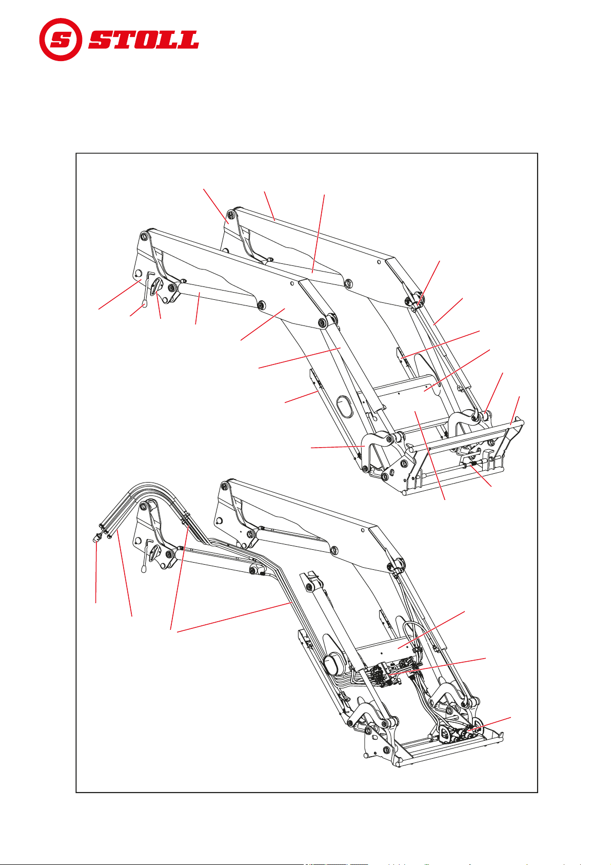
3.2 Structure of FZ front loaders
B064
11
11
2
2
3
3
4
4
5
5
6
6
7
7
9
9
10
10
12
12
13
13
14
14
15
15
16
16
17
17
1818
19
19
20
20
21
21
11
11
3
3
4
4
6
6
7
7
9
9
4
4
88
FZ front loaders are additionally equipped with parallel motion and are composed of the following main
components:
STRUCTURE
Fig. 8 FZ front loader
27 B58FZS 0000000078 EN 002
Page 29

STRUCTURE
Legend
1 Pillars (drive-in system)
2 Lifting arm (base frame)
3 Lifting cylinder: hydraulic cylinder for lifting and lowering
4 Deviation triangle of the parallel motion
5 Indicator for implement position
6 Implement cylinder: hydraulic cylinder for dumping and scooping (synchronised cylinder)
7 Parking supports
8 Rating plate
9 Lever mechanism dumping/scooping
10 Euro change frame (implement support)
11 Implement locking mechanism
12 Cap for hydraulic and electrical distribution and additional equipment
13 Front loader locking mechanism
14 Coupling holder
15 Control rod of the parallel motion
16 Hydraulic couplings for the 3rd and 4th control circuit (optional)
17 Hydraulic and electrical distribution valves for additional equipment
18 Cross tube
19 Hydraulic tubes
20 Hydraulic hoses to the tractor (interface on the mounting part)
21 Connection cable (optional, multiple versions possible)
Sizes, see 11 Technical specifications.
B58FZS 0000000078 EN 002 28
Page 30

3.3 Equipment variations
The table shows the different equipment variations for FS and FZ front loaders:
Equipment Front loader
Basic equipment
Parallel motion (mechanical) ─ ─ ● ●
Change frame
Euro ●●●●
SMS ○ ○ ○ ○
Skid-Steer ○○○○
Euro-MX combi-frame ○ ○ ○ ○
Euro-SMS combi-frame ○ ○ ○ ○
Euro-Alö Type 3 combi-frame ○ ○ ○ ○
Implement locking mechanism
mechanical ● ● ● ●
hydraulic ○ ○ ○ ○
Hydraulic and electrical couplings
4 Plug-in couplings ● ● ● ●
7-pin electrical plug connection ○ ● ○ ●
Hydro-Fix multiple hydraulic coupling ○ ○ ○ ○
Hydro-Fix multiple coupling
for hydraulic and electric
Tractor-specific multi-coupler (○) (○) (○) (○)
Additional functions
Comfort Drive (mechanical operation) ○ ○ ○ ○
Comfort Drive (electrical operation) ○ ○ ○ ○
2
3rd control circuit
4th control circuit
Rapid emptying ─ ● ─ ─
Quick emptying ─ ─ ─ ●
Return-to-Level ─ ─ ─ ●
Camera system ○ ○ ○ ○
○○○○
2
STRUCTURE
FS FS-rapid
emptying
○○○○
○○○○
FZ FZ-L
1
1
1
1
● = Series, ○ = Optional, ─ = not available, () = not for all tractors
1
Standard equipment on FZ 100
2
Alternatively with screw couplings, plug-in couplings or multiple couplings
29 B58FZS 0000000078 EN 002
Page 31

STRUCTURE
B06E
11 22
33
2211
3.4 Attaching it to the tractor
The front loader is attached to the tractor using the mounting kit for tractors. The mounting kit consists
of the following components:
Fig. 9 Mounting kit for tractors
Legend
1 Front guard left and right
2 Mounting parts left and right
3 Mountings/catch hooks
The components remain permanently mounted on the tractor. They can look different depending on the
tractor model.
Observe the installation instructions for the mounting kit.
Observe the regulations for the registration of the changed empty weight in the vehicle documents
for the tractor.
The front loader can only be mounted on the tractor if the associated mounting kit is already
installed. Only an authorized specialist workshop is allowed to install the mounting kit on the
tractor.
B58FZS 0000000078 EN 002 30
Page 32

3.5 Change frame
The change frame is a fixed component of the front loader. The different types are designed and
adapted for the mounting of standardised implements of this type.
As a matter of principle, the following change frames are available for FS and FZ 8 to 80.1 front loaders:
Euro change frame
SMS change frame
Euro-SMS Combi change frame
Euro-Alö
3
Combi change frame
Euro-FR Combi change frame
Skid-steer change frame
The basic equipment of the change frames includes a mechanical implement locking mechanism,
however, a hydraulic implement locking mechanism can be installed as an option (see 4.1 Implement
locking mechanism).
For FZ 100 front loaders, there is a reinforced Euro change frame, which is always equipped with
hydraulic implement locking.
The change frames will be presented without implements in the following.
STRUCTURE
3.5.1 Euro change frame
These change frames are installed on FS and
FZ 8 to 80.1 front loaders.
They are intended for mounting implements
complying with the Euro standard.
The implement cylinder serves to swivel the
change frame around its pivot point.
On the support, the couplings for a 3rd and
4th control circuit can be installed as an option
(see 4.9.1 Additional control circuits).
11
22
33
44
55667788
B06T
Fig. 10 Euro change frame
Legend
1 Implement cylinder
2 Upper cross bar
3 Support with hydraulic couplings for the
3rd/4th control circuit
4 Mounting on the left
5Spring
6 Lower cross bar
7 Mounting on the right
8 Pivot point
31 B58FZS 0000000078 EN 002
Page 33

STRUCTURE
B06J
11
22
11
2
2
B06K
3.5.2 SMS change frame
These change frames are installed on FS and
FZ 8 to 80.1 front loaders.
The implement is hinged on the top cross bar and
is secured with the locking mechanism.
Its function is similar to that of the Euro change
frame.
Fig. 11 SMS change frame
Legend
1 Upper cross bar
2 Locking mechanism
3.5.3 Euro-SMS Combi change frame
These change frames are installed on FS and
FZ 8 to 80.1 front loaders.
They are intended for mounting implements
complying with the Euro standard as well as the
SMS standard.
Euro implements are hinged onto the outer pins.
SMS implements are hinged onto the cross bar.
The function is the same as for Euro and
SMS change frames.
Fig. 12 Euro-SMS Combi change frame
Legend
1 Outer pin
2 Cross bar
B58FZS 0000000078 EN 002 32
Page 34

3.5.4 Euro-Alö3 Combi change frame
These change frames are installed on FS and
FZ 8 to 80.1 front loaders.
They are intended for mounting implements
complying with the Euro standard as well as the
Alö3 standard.
Euro implements are hinged onto the outer pins.
Alö3 implements are hinged onto the inner pin.
The function is the same as for Euro change
frames.
STRUCTURE
2
2
11
Fig. 13 Euro-Alö3 Combi change frame
Legend
1 Outer pin
2 Inner pin
B06L
3.5.5 Euro-FR Combi change frame
These change frames are installed on FS and
FZ 8 to 80.1 front loaders.
They are intended for mounting implements
complying with the Euro standard as well as the
FR standard.
For the use of FR implements, both supports
must be mounted on the outside of the change
frame and locked with linch pins. The mountings
are attached to the support when using Euro
implements.
The function is the same as for Euro change
frames.
44
33
22
11
Fig. 14 Euro-FR Combi change frame
Legend
1Pin
2Linch pin
3 Mounting
4 Support for mounting
33
B08H
33 B58FZS 0000000078 EN 002
Page 35

STRUCTURE
B076
11
22
11
5
5
4
4
3
3
2
2
B06I
3.5.6 Skid-steer change frame
These change frames are installed on FS and
FZ 8 to 20 front loaders.
They are intended for mounting implements
complying with the skid-steer standard.
The implement is attached to the locking hooks
using the lever.
Fig. 15 Skid-steer change frame
Legend
1 Lever
2 Locking hooks
3.5.7 Reinforced Euro change frame (FZ 100)
The structure of this change frame is similar to
the FS and FZ 8 to 80.1 Euro change frame.
However, they are designed for higher loads and
are always equipped with a hydraulic implement
locking mechanism (see 4.1.2 Hydraulic
implement locking mechanism – Hydro-Lock).
Fig. 16 Reinforced Euro change frame (FZ 100)
Legend
1 Upper cross bar
2 Support with hydraulic couplings for the
3rd/4th control circuit
3 Locking pins (left)
4 Hydraulic cylinder for the implement locking
mechanism
5 Locking pins (right)
B58FZS 0000000078 EN 002 34
Page 36

3.6 Hydraulic lines
⚠ CAUTION
There is a risk of injury due to escaping hydraulic fluids!
If the hydraulic lines are not depressurized before the coupling procedures, oil can spray out and injure
the skin or other body parts (e.g. eyes).
Always depressurize the hydraulic system before any coupling procedures.
Clean the couplings on a regular basis.
The tractor and front loader are connected with
4 hydraulic lines, which can be found in the right
pillar of the front loader.
A2A2 A1
B2B2 A2A2 A1A1 B1B1
A1 B1B1B2B2
STRUCTURE
Hydraulic line Colour of the
protective cap
A1 yellow Lifting function
A2 blue Scooping function
B1 green Lowering function
B2 red Dumping function
3.7 Hydraulic couplings
3.7.1 Plug-in couplings
The plugs of the plug-in couplings are located on
the hydraulic lines of the front loader.
The couplings can be found on the right-side
mounting part for the tractor. They are connected
to the hydraulic valve either directly or with hose
lines.
Plugs and couplings are equipped with coloured
caps to facilitate assignment.
Description
B061
Fig. 17 Hydraulic lines
A2A2A1A1B1B1 B2B2
Promptly replace damaged or missing
labels (e.g. caps).
B062
Fig. 18 Plug-in couplings connected
35 B58FZS 0000000078 EN 002
Page 37

STRUCTURE
B08L
11
11
B084
22
3.7.2 Multiple coupling Hydro-Fix
As an option, the front loader can be equipped
with the Hydro-Fix coupling. This enables
simultaneous connection of all hydraulic lines
with the couplings.
The Hydro-Fix upper part is located on the
hydraulic lines of the front loader. The Hydro-Fix
lower part is located on the right-side mounting
part for the tractor.
Fig. 19 Hydro-Fix: Position on the front loader
Legend
1 Hydro-Fix lower part
Fig. 20 Hydro-Fix
Legend
1 Hydro-Fix upper part
B58FZS 0000000078 EN 002 36
2 Hydro-Fix lower part
Page 38

4Functions
4.1 Implement locking mechanism
4.1.1 Mechanical implement locking mechanism
Euro, SMS and Combi change frames
⚠ WARNING
Risk of injury due to implements falling down!
The implement may fall down if the implement locking mechanism is open or not locked correctly. This
can cause serious injury to persons standing in the surrounding area.
Only actuate the implement locking mechanism when the implement is set down on the ground or
on a secure rack.
Always check that the implement is correctly locked.
⚠ CAUTION
FUNCTIONS
Risk of crushing due to spring tension!
There is spring tension on the handle of the implement locking mechanism, which closes the locking
mechanism when the handle is lifted. Improper use can lead to injury to hands and fingers.
Always operate the handle with one hand and grab it in the middle.
37 B58FZS 0000000078 EN 002
Page 39

FUNCTIONS
B06O
11
3
322
6
6
2
2
4
4 77 88
4
4
6
6
7
7
5
5
The mechanical implement locking mechanism
on Euro, SMS and Combi change frames is
actuated manually.
The implement is hinged with its hooks on the top
cross bar on the change frame.
Below, the implement rests on the bottom cross
bar. Both eyelets of the implement project into the
mountings of the change frame.
The locking mechanism is held open by the stop.
When lifting the handle, the locking mechanism is
closed by the spring, as the front loader pin is
pushed through the eyelets of the implement.
When scooping, the handle is lifted by a guide
piece on the lifting arm, and the locking
mechanism closes automatically.
Doe not raise the front load higher than
1.5 m until proper locking of the implement
locking mechanism has been checked!
Fig. 21 Open (top) and closed (bottom) locking
mechanism
Legend
1 Implement
2 Hook
3 Upper cross bar
4 Handle
5Stop
6Eyelet
7Spring
8 Lower cross bar
B58FZS 0000000078 EN 002 38
Page 40

FUNCTIONS
Skid-steer change frame
⚠ WARNING
Risk of injury due to implements falling down!
The implement may fall down if the implement locking mechanism is open or not locked correctly. This
can cause serious injury to persons standing in the surrounding area.
Only actuate the implement locking mechanism when the implement is set down on the ground or
on a secure rack.
Always check that the implement is correctly locked.
⚠ CAUTION
Risk of crushing due to spring tension!
There is spring tension on the handle of the implement locking mechanism, which closes the locking
mechanism when the handle is lifted. Improper use can lead to injury to hands and fingers.
Always operate the handle with one hand and grab it in the middle.
The mechanical implement locking mechanism
on skid-steer change frames is actuated
manually.
To attach implements, the edge of the mounting
surfaces is pushed into the mounting on the
implement. As soon as the implement is resting
on the change frame, the locking mechanism is
closed with the lever. The locking hooks then
engage with the lug on the implement.
1
1
2
2
Fig. 22 Mechanical implement locking mechanism on
Legend
1Lever
2 Mounting surface
3 Locking hooks
4.1.2 Hydraulic implement locking mechanism – Hydro-Lock
⚠ WARNING
Risk of injury due to implements falling down!
If not installed or operated correctly, the implement can fall down. This can cause serious injury to
persons standing in the surrounding area.
The hydraulic implement locking mechanism must only be installed by a specialist workshop.
Only use switches that are approved by STOLL.
Set the implement on the ground or on a safe support before using the implement locking function.
As an option, the front loader can be equipped with a hydraulic implement locking mechanism.
It attaches the implement to the change frame via 2 pins activated by a hydraulic cylinder.
33
B06M
skid-steer change frames
39 B58FZS 0000000078 EN 002
Page 41

FUNCTIONS
B01J
11
33
2
2
4.2 Basic functions
⚠ DANGER
Lethal danger due to loads falling down from front loaders without parallel motion!
On front loaders without parallel motion, the implement tilts to the rear when lifting. As a result, the load
can fall on the driver and cause lethal injuries.
Watch the load as you are lifting. Do not lift the load when reversing.
Compensate for the increased angle on front loaders without parallel motion when lifting by
“dumping” with the implement.
⚠ WARNING
Risk of injury and material damage caused by falling loads or lowering front loader!
With dumping implements that are long or protrude far to the front, the centre of gravity can shift and
cause the pressure relief valve of the front loader to open by itself. As a result, the front loader dumps
or lowers uncontrollably and can lead to serious injuries and damage.
Observe the maximum load of the front loader (see 11 Technical specifications).
Always use sufficient counterweights at the rear of the tractor (see 5.3.2 Ballasting).
During loading work, instruct persons to exit the working area (see 2.8 Danger zones).
The front loader has 4 basic functions that are required to move the lifting arms and the implement.
Lifting
The 2 lifting cylinders are extended and thus
raise the lifting arm and the implement.
Without parallel motion, the angle between the
lifting arm and the implement remains constant
so that the implement changes its orientation.
With parallel motion, the angle between the lifting
arm and the implement changes so that the
implement maintains its original orientation.
To move the implement, see 4.5 Parallel
motion (FZ, FZ-L).
Fig. 23 Lifting function
Legend
1 Lifting cylinders on the left and right
2 Lifting arm
3 Implement
B58FZS 0000000078 EN 002 40
Page 42

Lowering
B01K
11
2
2
3
3
The 2 lifting cylinders are retracted and thus
lower the lifting arm and the implement.
Without parallel motion, the angle between the
lifting arm and the implement remains constant
so that the implement changes its orientation.
With parallel motion, the angle between the lifting
arm and the implement changes so that the
implement maintains its original orientation.
To move the implement, see 4.5 Parallel
motion (FZ, FZ-L).
FUNCTIONS
Fig. 24 Lowering function
Legend
1 Lifting cylinders on the left and right
2Lifting arm
3Implement
Scooping
The 2 implement cylinders are retracted and thus
swivel the implement upwards. The implement
scoops.
1
1
22
Fig. 25 Scooping function
Legend
1 Implement cylinders on the left and right
2Implement
B01L
41 B58FZS 0000000078 EN 002
Page 43

FUNCTIONS
B01M
22
1
1
Dumping
The 2 implement cylinders are extended and thus
swivel the implement downwards. The load is
dumped out.
Fig. 26 Dumping function
Legend
1 Implement cylinders on the left and right
2 Implement
B58FZS 0000000078 EN 002 42
Page 44

4.3 Float position
⚠ WARNING
Possible risk of injury due to unexpected movement!
If the front loader is not completely lowered, a vacuum may form in the hydraulic cylinders during the
float position. This causes uncontrolled lowering of the front loader at a later time. This can cause
persons to be injured or crushed.
Only use the float position when the front loader is completely lowered.
Do not use the float position with implements that require the presence of other persons!
Only use the float position if nobody is in the danger zone.
Do not scoop while in float position.
⚠ WARNING
Possible risk of injury due to unexpected movement!
On FZ-RTL front loaders, the front loader may "sag" during quick emptying if it had previously scooped
when the float position was switched on. This can cause persons to be injured or crushed.
Do not use the float position with implements that require the presence of other persons!
Only use the float position if nobody is in the danger zone.
Do not scoop while in float position.
FUNCTIONS
⚠ WARNING
Possible risk of injury due to the implement tipping over!
On FS front loaders, the float position for the implement may not be activated for the scooping and
dumping functions. This could cause the implement to tip over unintentionally to the rear. This may
result in serious accidents.
The activation of the float position must be ruled out through the assembly on FS front loaders. If
this is not the case, work with the front loader must be stopped immediately and the specialist
workshop must be contacted, to have the float position deactivated for the scooping and dumping
functions. The front loader may only be used again when the float position has been deactivated for
the scooping and dumping functions.
The float position is used to improve ground adaptation, since the implement can then follow the ground
contours and "floats" on it.
43 B58FZS 0000000078 EN 002
Page 45

FUNCTIONS
B008
11
22
3
3
4.3.1 Lifting arm float position
For the float position of the lifting arms, the
hydraulic cylinders are depressurized, i.e., they
are open towards the tank. The front loader lies
on the ground through the pressure of its own
weight.
Activating the lifting arm float position:
(1) Fully lower the front loader.
(2) Move the operating lever all the way to the
front until it engages (see 6.1 Operating
elements).
The float position is activated.
Fig. 27 Front loader in float position
Legend
1 Hydraulic cylinder
2 Implement
3Ground
4.3.2 Implement float position
For the implement float position, the front loader must be equipped with Hydac valves as well as parallel
motion and must have a STOLL Pro Control operating element.
The float position for the implement must be explicitly activated in STOLL Pro Control during the
installation.
Activating the implement float position:
(1) Lower the front loader close to the ground.
(2) Move the operating lever to the right and press button T2 (green) (see 6.1.4 STOLL Pro Control).
The float position is activated.
B58FZS 0000000078 EN 002 44
Page 46

4.4 Indicator for implement position
The indicator for the implement position is
located on the left implement cylinder. It allows
the horizontal position of the implement to be
read from the driver's seat.
The rod is attached on the lower bearing pin and
runs through the tube, which is attached to the
upper bearing pin with the support. When
dumping or scooping, the rod moves in the tube.
When the implement is in horizontal position, the
rod and the tube are flush.
Setting of the indicator:
(1) Position the implement horizontally.
(2) Lower the front loader to the ground.
(3) Switch off the tractor.
Apply the parking brake.
Stop the engine.
FUNCTIONS
11
2
2
3
3
4
4
(4) Loosen the clamping screw.
(5) Push the tube into the support until the top
end of the tube is flush with the rod.
(6) Tighten the clamping screw.
The indicator is set.
4.5 Parallel motion (FZ, FZ-L)
With the parallel motion, the guide linkage
ensures constant orientation/inclination of the
implement.
The function is particularly suitable for loading
pallets and stacking bales.
The function can only be executed when
the implement is horizontal or in scooping
position.
B01E
Fig. 28 Indicator for implement position
Legend
1 Clamping screw
2 Holder
3Tube
4Rod
B06G
Fig. 29 Parallel motion
45 B58FZS 0000000078 EN 002
Page 47

FUNCTIONS
B06H
4.6 Rapid traverse emptying (FS) and quick emptying (FZ-L)
⚠ CAUTION
Possible risk of accidents due to improper use of the rapid emptying!
If the rapid emptying is actuated outside of a dumping process, it can cause a strong pressure drop in
the hydraulic system. The resulting imprecise and uncontrolled working behaviour of the front loader
can cause accidents.
Only use the rapid emptying during dumping processes.
⚠ CAUTION
Risk of accident due to improper use of the rapid and quick emptying!
Use of the rapid or quick emptying on implements with hydraulic functions can cause damage to the
hydraulic lines. This increases the risk of accidents.
Only use the rapid or quick emptying with implements that do not have hydraulic functions.
Rapid emptying (FS rapid emptying)
An additional valve on the implement cylinder
ensures faster dumping of the implement during
the rapid emptying.
In this case, the hydraulic fluid is diverted from
the scooping side of the implement cylinder to the
dumping side, so that the pump is relieved.
See 6.1 Operating elements for how to
operate the rapid emptying.
Quick emptying (FZ-L)
With quick emptying, an additional valve on the
implement cylinder causes the load to be
dumped immediately.
The valve establishes a connection between the
scooping side and the dumping side of the
implement. The dumping process starts when
pressing the button and is accelerated by the
implement's own weight and that of the load.
When the button is actuated, the
implement dumps the load immediately
without hydraulic actuation.
See 6.1 Operating elements for how to
operate the quick emptying.
Fig. 30 Rapid or quick emptying
B58FZS 0000000078 EN 002 46
Page 48

4.7 Return-To-Level (FZ-L)
⚠ WARNING
Possible risk of injury due to uncontrolled lowering!
Actuation of the RTL button while dumping causes the front loader to be lowered. Moreover, when
dumping with insufficient fluid supply, a vacuum can form in the implement cylinder, which also causes
lowering of the front loader. This can cause injury to persons standing in the surrounding area.
Only press the RTL button when lowering the front loader.
Throttle the oil flow as little as possible.
If necessary, increase the idling speed.
The return-to-level sensor is located on the
indicator on the left implement cylinder. It enables
automatic lowering of the front loader to its preset position by pressing a button. This mainly
facilitates loading work that involve repetitive
movement.
To do so, an additional valve on the implement
cylinder diverts the hydraulic fluid flowing out
while lowering. The sensor monitors the position
of the implement and emits the signal for closing
the valve as soon as the implement has reached
its pre-set position.
FUNCTIONS
Fig. 31 Return-to-level function
B06F
47 B58FZS 0000000078 EN 002
Page 49

FUNCTIONS
11
4
4
5
5
2
2
B06R
33
Setting the return-to-level position:
(1) Position the implement horizontally.
(2) Lower the front loader to the ground.
(3) Switch off the tractor.
Apply the parking brake.
Stop the engine.
(4) Loosen the clamping screw.
(5) Push the tube in the support until there is a
space of about 10 mm between the top end
of the rod and the top edge of the sensor.
(6) Tighten the clamping screw.
(7) Switch on the tractor.
(8) Lift and dump the front loader.
(9) Slowly lower the front loader and press the
RTL button at the same time
(see 6.1 Operating elements).
(10) Check the position of the implement.
If necessary, push the tube up or down.
The return-to-level position is set.
4.8 Anti-lowering guard
⚠ WARNING
Risk of injury and accident due to implement tipping off!
The anti-lowering guard only prevents the front loader from lowering, however, it does not prevent
accidental dumping of the implement. Persons whose presence is required near the load can be injured
by the load falling down.
Do not move the front loader as long as people are standing in the danger zone.
Only start the lifting operation after everybody has left the danger zone.
The anti-lowering guard in compliance with EN 12525/A1 prevents sudden lowering of the front loader.
It is used when working with a raised front loader if the presence of persons is required in the machine's
working area.
The anti-lowering guard is not suitable for use with work cages that are used to transport people.
The operating state of the anti-lowering guard is shown by the lamp on the switch box. If the lamp is on,
the anti-lowering guard is activated. If the lamp is off, the anti-lowering guard is deactivated. In this case,
there may not be any one standing in the working area of the front loader (see 2.8 Danger zones). When
the anti-lowering guard is activated, the lifting function is possible and the lowering function is locked.
Fig. 32 Return-to-level sensor on the indicator
Legend
1 Sensor
2 Clamping screw
3Holder
4 Tube
5Rod
B58FZS 0000000078 EN 002 48
Page 50

4.9 Additional functions
4.9.1 Additional control circuits
⚠ WARNING
Risk of injury due to unexpected movement of the front loader or implement!
If there is an electrical malfunction, operating elements can be temporarily or permanently out of
function. As a result, it is possible that an unintended function is triggered instead of the selected
implement functions (see 3rd control circuit and 4th control circuit). The triggering of unwanted
functions can lead to unexpected movement of the front loader or implement and cause serious injuries.
Before use, check all of the front loader functions without a load.
In case of malfunction, stop working with the front loader immediately and contact the specialist
workshop.
For hydraulic functions of the implement, additional control circuits must be installed. The
corresponding hydraulic couplings are located on the change frame and are available as plug-in, screwin or multiple couplings.
3rd control circuit
With a switch valve for the 3rd control circuit,
hydraulic implement functions are enabled, e.g.
the actuation of a top loading grip.
FUNCTIONS
To operate the 3rd control circuit,
see 6.1.6 Switch/changeover switch.
11
B06W
Fig. 33 Additional 3rd control circuit
Legend
1 Screw or plug-in coupling for the 3rd control circuit
49 B58FZS 0000000078 EN 002
Page 51

FUNCTIONS
B06V
11
22
4th control circuit
With a switch valve for the 4th control circuit,
additional hydraulic implement functions are
enabled.
To operate the 4th control circuit,
see 6.1.6 Switch/changeover switch.
To operate the multiple coupling,
see 3.7.2 Multiple coupling Hydro-Fix.
Fig. 34 Additional 4th control circuit
Legend
1 Multiple coupling for 4th control circuit
2 Multiple coupling for 3rd control circuit
Mark the hydraulic couplings on the front loader and implements appropriately to avoid
confusion.
Promptly replace damaged or lost labels (e.g. coloured caps).
4.9.2 Comfort Drive
⚠ WARNING
Possible risk of crushing!
The front loader is lowered when the Comfort Drive is switched on.
Before switching on the Comfort Drive, lower the front loader completely to the ground.
NOTICE
Possible material damage due to overloading!
The Comfort Drive can be overloaded when working with heavy loads (e.g. excavation) and with the
pallet fork, resulting in damage.
Switch off the Comfort Drive before working with heavy loads.
The Comfort Drive function enables smoother and more comfortable driving with a mounted front loader
during transport and when driving on roads. There is a piston accumulator for this purpose in the cross
tube, which absorbs impact loads caused by driving on uneven ground.
To achieve optimal function of the Comfort Drive, lower the front loader again a little bit after
lifting.
B58FZS 0000000078 EN 002 50
Page 52

Gas-hydraulic Comfort Drive
The gas-hydraulic Comfort Drive is operated by
hand. The shut-off valve is located on the cross
tube of the front loader for this purpose.
Lever position Function
Vertical Comfort Drive on
Horizontal Comfort Drive off
Electro-hydraulic Comfort Drive
FUNCTIONS
11
2
2
Fig. 35 Manually actuated Comfort Drive
1 Cross tube
2 Shut-off valve on the valve
B06X
⚠ WARNING
Possible risk of crushing!
Comfort Drive is also activated by switching off the ignition or disconnecting the electrical supply. The
front loader can lower slightly in the process and cause personal injury.
Completely lower the front loader before switching off the ignition or disconnecting the electrical
supply of the front loader.
⚠ WARNING
Risk of injury and accident due to the front loader lowering!
Accidental actuation of the Comfort Drive switch while driving can cause the front loader to lower, and
if the lifting height is too low (less than 1 m) the front loader can touch down on the ground. This can
cause accidents and people can be severely injured.
Make sure that the front loader is raised high enough while driving (at least 1 m).
The electro-hydraulic Comfort Drive is actuated
with a switch in the driver's cab.
As a standard, the electro-hydraulic valve is open
here, i.e. it is active when there is no voltage at
the valve.
Indicator light Description
ON Comfort Drive on
OFF Comfort Drive off
11
The electro-hydraulic Comfort Drive can
also be operated with STOLL Pro Control
(see 6.1.4 STOLL Pro Control).
Fig. 36 Switch-operated Comfort Drive
Legend
1 Switch position ON
2 Indicator light
3 Switch position OFF
22
33
B06Y
51 B58FZS 0000000078 EN 002
Page 53

FUNCTIONS
B08K
11
4.9.3 Lowering throttle
⚠ WARNING
Possible material damage due to overloading!
The front loader can be lowered unevenly and be distorted when the two lowering throttles are not
adjusted in the same way, and can cause personal injury.
Set both lowering throttles to the same values.
The lowering throttle is used to set the lowering
speed of the front loader.
There is one lowering throttle on each side of the
lifting arm. Each lowering throttle is adjusted with
the rotary knob. There are numbers on the rotary
knob to enable more precise adjustment.
4.9.4 Camera system
NOTICE
Material damage due to loss of suction force!
Due to a natural loss of vacuum, the suction holder can lose suction force and fall off. This can damage
the camera system.
Detach the suction holder at regular intervals and fix it in place again.
NOTICE
Material damage due to adhesion!
If the suction holder is in contact with the window for too long, it can firmly adhere to the window and
damaged it.
Detach the suction holder at regular intervals and fix it in place again.
The camera system consists of a monitor, a camera and the corresponding cable sets.
It enables more precise work with the front loader and the mounted implements.
Fig. 37 Lowering throttle
Legend
1 Rotary knob
Observe the supplied documentation for the camera system.
B58FZS 0000000078 EN 002 52
Page 54

5Start-up
5.1 Initial operation
The initial operation is executed at a specialised workshop. This also includes mounting of the front
loader as well as a functional check.
Obtain instruction from the specialised workshop and ask questions if necessary.
Read the operating instructions before initial use.
After the first 5 hours of operation, have a specialised workshop re-tighten all of the mounting
screws.
Check all of the front loader functions without a load.
5.2 Check before each start-up
Before each start-up, check all of the points on the checklist.
Fix any observed defects in a safe position and location.
START-UP
Only use the front loader if proper and safe operation is ensured.
Checks See also Completed
Before mounting the front loader
Are the safety labels on the tractor and on the front loader complete and in
order?
Are the brake pedals connected? Section 5.3.1
Hydraulic oil: Is there enough oil?
Is the front axle turned off?
Is the shut-off valve of the front power lift closed?
Is the pressure of the tires sufficient for operating the front loader?
Is the correct counterweight mounted on the rear? Section 5.3.2
Are the fixing screws of the mounting parts tightened? Section 5.1 Initial
Are the mountings (bearings and sliding surfaces) on the mounting parts clean,
free from paint, and greased?
Are the front loader locking mechanisms lubricated? Section 8.1.1
During mounting
Are the hydraulic lines connected correctly? Section 6.3
Is the electric cable of the front loader connected?
Are the front loader locking mechanisms positioned correctly? Section 5.4.1
Section 2.10
Adhesive safety label
Preparations on the
tractor
Operating
instructions of the
tractor
Ballasting
operation
Section 8.1.1
Lubrication points
Lubrication points
Operating the
hydraulic couplings
Adjusting the FS and
FZ 8 to 50 front
loader locking
mechanism,
Section 5.4.2
Adjusting the "Double
locking mechanism"
FZ 50 to 100 front
loader locking
mechanism
53 B58FZS 0000000078 EN 002
Page 55

START-UP
B00C
Checks See also Completed
After mounting
Are the parking supports folded away and secured? Section 6.2
Is the front loader locking mechanism locked properly? Section 8.2.3 Service
Is the locking mechanism for the implement locked properly? Section 4.1
Mudguards adjusted for front loader operation?
Functional test carried out?
(Basic functions and additional functions)
5.3 Preparations
5.3.1 Preparations on the tractor
Operating the parking
supports
instructions for front
loader locking
mechanism
Implement locking
mechanism
Section 6.1
Operating elements
NOTICE
Material damage due to divided brakes on the tractor!
When the front loader is mounted, one-sided braking can lead to serious damage.
Couple the brake pedal in the tractor before using the front loader.
The divided brake pedal serve to support the
steering of the tractor and can brake the
respective wheels on each side. Therefore, for
example, small turning radii can be achieved
when driving on roads. When the front loader is
mounted, it is recommended to couple the brake
pedals before start-up.
Fig. 38 Coupling the brake pedals
B58FZS 0000000078 EN 002 54
Page 56

5.3.2 Ballasting
≥ 20%
B079
⚠ WARNING
Serious injury due to the machine falling over!
When working with the front loader without rear counterweights, the tr acto r can tip over and c ause injury
to the driver and persons in the surroundings. Moreover, there is the risk of overloading the front axle
of the tractor.
For front loader work, always use sufficient counterweight at the rear of the tractor.
The proper ballasting of the tractor is very
important to achieve sufficient stability. This
stability is influenced by the centre of gravity of
the loaded tractor / front loader combination, the
geometrical conditions, the weight, the
arrangement of the implement and the load in the
implement, the track width and wheel base of the
tractor, acceleration and braking processes as
well as the road conditions, to name a few. A
significant measure to increase the stability is the
addition of counterweights or rear weights, which
is strongly recommended for all front loader work.
If operation with a rear weight is not possible, the
stability can be increased with appropriate
ballasting on the rear wheels (wheel weights) or
with liquid in the tyres.
To determine the require weight for ballasting, the
following conditions apply:
When the front loader is fully loaded with the
implement in the most forward position, the rear
axle must carry min. 20 % of the total weight (sum
of the weight of the tractor, the front loader, the
implement, the load and the counterweight)
(see Fig. 39). This ensures stability and braking
efficacy.
When the front loader is raised without an
implement, the front axle must carry min. 20 % of
the total weight (see Fig. 40). This ensures the
steering capacity while driving.
START-UP
≥ 20%
B078
Fig. 39 Load for front loader work
Observe the operating instructions of the
tractor as well as the permissible axle loads
for the front and rear axles.
Fig. 40 Load for driving on roads
55 B58FZS 0000000078 EN 002
Page 57

START-UP
G
b
N
+
l
2
l
1
M
+
B08N
The formula to precisely determine the rear
weight is specified in DIN EN 12525:2000-A2:
P Weight of the tractor in kg
M Weight of the counterweight in kg
N Weight of the implement in kg
G Rear axle load in kg
b The distance between the centre of gravity
l
1
l
2
(incl. front loader and change frame without
counterweight)
(incl. the maximum permissible load of the
implement)
Remark: The maximum permissible load is
the maximum load that can be safely lifted
by the hydraulic system. This can be limited
by the shape or the density of the load. If
several different implements are used, the
most unfavourable case should be taken
for the calculation.
(incl. front loader and change frame with
the maximum ranges without
counterweight)
of the load in the implement and the centre
of the front axle with the maximum range in
mm
Distance between the centre of gravity of
the counterweight and the centre of the
rear axle in mm
Wheel base of the tractor in mm
Fig. 41 Calculation of the static stability
Observe the respective current version of
DINEN12525.
B58FZS 0000000078 EN 002 56
Page 58

5.4 Adjusting the front loader locking mechanism
11
B06B
⚠ CAUTION
Possible injuries and material damage caused by incorrectly adjusted front loader locking
mechanism!
Improper adjustment of the front loader locking mechanism can cause movement of the front loader in
the mountings and damage them. This can cause the front loader to fall down and injure persons in the
surrounding or cause material damage.
Always check the front loader locking mechanism when mounting and dismounting.
Check the front loader locking mechanism regularly and readjust if necessary.
On new front loaders, re-tighten the locking mechanism after the first hours of operation in order to
compensate for any loosening caused by smoothing of the surfaces.
5.4.1 Adjusting the FS and FZ 8 to 50 front loader locking mechanism
Adjusting the front loader locking mechanism:
Open-ended spanner 24 mm WAF
Ratchet ½" with extension, joint and socket
wrench (nut) 24 mm
START-UP
(1) Completely open the front loader locking
mechanism.
Move the lever upwards.
Fig. 42 Opening the front loader locking mechanism
Legend
1Lever
57 B58FZS 0000000078 EN 002
Page 59

START-UP
11
33
22
B06C
44
3
3
2
2
1
1
B06D
(2) Guide the open-ended spanner through the
guide slot of the lever.
Fig. 43 Attaching the implement
Legend
1 Open-ended spanner
2 Guide slot
3 Ratchet
(3) Loosen the locknut.
(4) Adjust the clamping wedge with the screw.
(5) Tighten the locknut.
(6) Check the front loader locking mechanism.
Close and open the front loader locking
mechanism.
Use the required manual force.
If necessary, readjust the front loader
locking mechanism.
The front loader locking mechanism is
adjusted.
Fig. 44 View of the front loader locking mechanism
from below
Legend
1 Lever
2 Clamping wedge
3 Locknut
4Screw
B58FZS 0000000078 EN 002 58
Page 60

START-UP
5.4.2 Adjusting the "Double locking mechanism" FZ 50 to 100 front loader locking mechanism
On the FZ 50 front loader, the double locking mechanism is installed as an option.
Adjusting the front loader locking mechanism:
Open-ended spanner 30 mm WAF
Ratchet ½" with extension, joint and socket
wrench (nut) 30 mm
(1) Open the front loader locking mechanism.
Move the lever upwards.
(2) Loosen the locknut with the open-ended
spanner.
332211
Fig. 45 Opening the front loader locking mechanism
Legend
1Lever
2 Turning lock
3Locknut
2211
Fig. 46 Attaching the implement
B07Y
B07Z
Legend
1Locknut
2 Open-ended spanner
59 B58FZS 0000000078 EN 002
Page 61

START-UP
2211
B080
11
B083
22
2211
B07Z
(3) Close the front loader locking mechanism.
(4) Guide the socket wrench through the
(5) Unscrew the screw.
Push the lever down.
grommet to the screw.
Fig. 47 Guiding the socket wrench through to the screw
Legend
1 Socket wrench
2 Lever
Observe the disc spring.
(6) When the disc spring is at maximum tension
(no more gap to the turning lock), turn it back
by ¼ turn to relieve the tension.
(7) Open the front loader locking mechanism.
(8) Tighten the locknut.
(9) Close the front loader locking mechanism.
The front loader locking mechanism is
adjusted.
Fig. 48 View of the front loader locking mechanism
from below
Legend
1 Turning lock
2Screw
Fig. 49
Legend
1 Locknut
2 Open-ended spanner
B58FZS 0000000078 EN 002 60
Page 62

5.5 Mounting the front loader
⚠ WARNING
Risk of injury due to uncontrolled movements!
Uncontrolled movements of the front loader can cause injury to persons assisting in the surrounding
area.
Only mount the front loader when nobody is standing the the danger area (see 2.8 Danger zones).
Before exiting the driver's cab, switch off the tractor and depressurize the hydraulic system.
⚠ WARNING
Risk of injury and accident when the front loader is not locked correctly!
When the front loader locking mechanism is not adjusted correctly, the front loader can slip out of the
mounting and cause accidents or personal injury.
Make sure that the front loader locking mechanism is adjusted correctly.
Mounting the front loader:
(1) Open the front loader locking mechanism.
Push both locking levers up.
START-UP
Fig. 50 Opening the front loader locking mechanism
(2) Slowly drive the tractor centrally in the lifting
arm.
Ensure that the two locking pins touch the
slide rails and the catch hooks.
Fig. 51 Driving the tractor into the lifting arm
If it is not possible to fully drive the tractor up to the lifting arm, the front loader must be aligned
for mounting (see 5.6 Aligning the front loader for mounting).
B07D
B07E
61 B58FZS 0000000078 EN 002
Page 63

START-UP
B07F
B07G
B07H
(3) Switch off the tractor.
(4) Connect the hydraulic lines of the front
Apply the parking brake.
Stop the engine.
Depressurize the hydraulic system. To do
so, move all of the operating levers to the
end position.
loader (see 6.3 Operating the hydraulic
couplings).
(5) Connect the electric cables.
(6) Start the tractor.
(7) Lock the front loader pins in the front loader
mountings.
Use the lifting function until the front
loader pins are locked in the mountings.
(8) Close the front loader locking mechanism.
Use the lifting function until the front
loader is just above the ground.
Apply the parking brake.
Stop the engine.
Shift both locking levers downwards.
(9) Fold in the parking supports.
Fold in both parking supports (see
6.2 Operating the parking supports).
The front loader is mounted and ready for
operation.
Fig. 52 Switching off the tractor and connecting the
hydraulic lines
Fig. 53 Locking the pins in the front loader mountings
Fig. 54 Folding in the parking supports and closing the
front loader locking mechanism
B58FZS 0000000078 EN 002 62
Page 64

5.6 Aligning the front loader for mounting
⚠ WARNING
Risk of injury and accident when the front loader is not locked correctly!
When the front loader locking mechanism is not adjusted correctly, the front loader can slip out of the
mounting and cause accidents or personal injury.
Make sure that the front loader locking mechanism is adjusted correctly.
NOTICE
Material damage due to abrupt operation!
When aligning the front loader, abrupt movements can cause damage to the front loader and the
mountings.
Before mounting the front loader, check that the operating lever moves smoothly.
Make sure that the tractor and front loader are operated gently.
If the front loader is being mounted for the first time or if it was previously used with a different tractor,
the front loader pillars can be too high or too low for mounting. In this case, the front loader has to be
aligned for mounting.
START-UP
Aligning and mounting the front loader:
(1) Release the front loader locking mechanism.
Push both locking levers up.
(2) Slowly drive the tractor centrally in the lifting arm.
Drive the tractor forwards until the mountings are as close as possible to the front loader pillars.
(3) Switch off the tractor.
Apply the parking brake.
Stop the engine.
Depressurize the hydraulic system.
(4) Connect the hydraulic lines.
(5) Connect the electric cables.
(6) Start the tractor.
(7) Align the front loader pillars.
Use the lifting, lowering, dumping and scooping functions until the front loader pillars are at the
right height.
(8) Drive the tractor forwards until the two locking pins touch the slide rails and the catch hooks.
The front loader is aligned for mounting on the tractor.
(9) Close the front loader locking mechanism.
Use the lifting function until the front loader is just above the ground.
Apply the parking brake.
Stop the engine.
Shift both locking levers downwards.
(10) Fold in the parking supports.
Fold in both parking supports (see 6.2 Operating the parking supports).
The front loader is mounted and ready for operation.
63 B58FZS 0000000078 EN 002
Page 65

OPERATION
6Operation
6.1 Operating elements
6.1.1 Basic controls with levers
⚠ WARNING
Possible risk of injury due to uncontrolled movement of the front loader!
If the control unit was not actuated for a longer period of time, there may be e.g. temperature differences
between the hydraulic fluid and the control unit. This can cause the control valves to jam and the front
loader moves uncontrollably. This may result in serious accidents.
At ambient temperatures lower than 10 °C and when the front loader is not used for longer than
15 minutes, always first actuate the scooping and dumping functions at a standstill to warm up the
control unit.
Only use the lifting and lowering functions after the warm-up phase.
⚠ WARNING
Possible risk of injury due to the implement tipping over!
On FS front loaders, the float position for the implement may not be activated for the scooping and
dumping functions. This could cause the implement to tip over unintentionally to the rear. This may
result in serious accidents.
The activation of the float position must be ruled out through the assembly on FS front loaders. If
this is not the case, work with the front loader must be stopped immediately and the specialist
workshop must be contacted, to have the float position deactivated for the scooping and dumping
functions. The front loader may only be used again when the float position has been deactivated for
the scooping and dumping functions.
B58FZS 0000000078 EN 002 64
Page 66

Depending on the equipment of the tractor,
00
DD
SS
CC
BBAA
B01N
0
0
different operating levers can be installed for the
front loader. In most cases, it is a cross lever or a
joystick. On some tractors, there are 2 operating
levers for the control of the front loader.
The figures show a top view of the assignment for
one operating lever (see Fig. 55) and 2 operating
levers (see Fig. 56).
The symbols marked in red are also found
on the operating lever in the tractor. If they
are missing, you must affix such symbols
according to DIN EN 12525 to clearly mark
each function.
Setting Assignment
0 Zero setting
A Dumping
B Scooping
CLifting
D Lowering
S Float position
OPERATION
Fig. 55 Assignment with one operating lever
SS
DD
AA
The float position is the only position of the
lever in which it may latch in.
0
CC
Fig. 56 Assignment with 2 operating levers
0
BB
B01P
65 B58FZS 0000000078 EN 002
Page 67

OPERATION
6.1.2 Tractor's own operating lever
⚠ WARNING
Risk of injury due to unexpected movement of the front loader!
The front loader can move unexpectedly as a result of unintentional actuation of the operating lever or
by programmed sequences. This can cause injury to persons in the surrounding area.
Lock the operating lever in the zero setting when the front loader is not in use.
If it is not possible to lock the operating lever, close the shut-off valve in the lifting hydraulic line.
Immobilise the lock-in position of the hydraulic control units.
Before using the front loader, immobilise or disconnect other implements on the tractor.
Immobilise or disconnect the front loader before using other implements.
Never use programmed sequences for the front loader.
⚠ WARNING
Risk of accident due to wrong assignment of the hose lines!
If the front loader is connected directly to the auxiliary control units of the tractor with hose lines,
swapping of the hose lines can result in incorrect assignment of the functions on the operating lever.
This can result in unexpected movements and accidents.
Always mark the couplings on the hose lines and connection points.
Promptly replace damaged or missing labels.
Connect the hose lines so that the float position takes place in the actuation direction of the lowering
function.
After connecting, check all of the functions of the front loader while at a standstill.
The operating lever can look different depending on the tractor model. However, the control of basic
functions remains the same (see 6.1.1 Basic controls with levers).
The assignment of the buttons is arranged as follows:
Operating lever with one button
Button Front loader Function Additional function with
changeover switch
A FS, FZ 3rd control circuit -
FS-rapid
emptying
Rapid emptying 3rd control circuit 4.6 Rapid traverse
emptying (FS) and quick
emptying (FZ-L)
Operating lever with 2 buttons
Button Front loader Function Additional function with
changeover switch
A FS, FZ 3rd control circuit -
FS-rapid
emptying
FZ-L Quick emptying 3rd control circuit
B FS, FZ 4th control circuit -
FZ-L Return-to-Level 4th control circuit 4.9.1 Additional control
Rapid emptying 3rd control circuit 4.6 Rapid traverse
emptying (FS) and quick
emptying (FZ-L)
circuits
B58FZS 0000000078 EN 002 66
Page 68

Operating lever with 3 buttons
Button Front loader Function Additional function with
A FS, FZ 3rd control circuit
FS-rapid
emptying
FZ-L Quick emptying 3rd control circuit
B FS, FZ 4th control circuit
FZ-L Return-to-Level
C All 4th control circuit
Lock the operating lever in the zero position when driving on roads to prevent accidental
actuation of the front loader!
6.1.3 STOLL Base Control
The STOLL "Base Control" operating lever is a
single-lever control unit with up to 3 push-button
switches for additional functions of the front
loader and as an option, 2 micro-buttons on the
sides for tractor functions.
Moreover, the Base Control also has a locking
function, e.g. for driving on roads.
When the locking function is activated, it is
not possible to move the operating lever.
OPERATION
changeover switch
Rapid emptying 3rd control circuit 4.6 Rapid traverse
A
A
B
B
C
C
emptying (FS) and quick
emptying (FZ-L)
DD
E
E
The control of the operating lever is the same as
the basic controls in 6.1.1 Basic controls with
levers.
Fig. 57 Base Control with 5 buttons
The assignment of the buttons for the individual front loader types is shown in the following tables:
Operating lever with one button
Button Front loader Function Additional function with
changeover switch
A FS, FZ 3rd control circuit -
FS-rapid
emptying
Rapid emptying 3rd control circuit 4.6 Rapid traverse
emptying (FS) and quick
emptying (FZ-L)
Operating lever with 2 buttons
Button Front loader Function Additional function with
changeover switch
A FS, FZ 3rd control circuit -
FS-rapid
emptying
FZ-L Quick emptying 3rd control circuit
B FS, FZ 4th control circuit -
FZ-L Return-to-Level 4.9.1 Additional control
Rapid emptying 3rd control circuit 4.6 Rapid traverse
emptying (FS) and quick
emptying (FZ-L)
circuits
B00N
67 B58FZS 0000000078 EN 002
Page 69

OPERATION
B01A
11
Operating lever with 3 buttons
Button Front loader Function Additional function with
A FS, FZ 3rd control circuit
B FZ-L Return-To-Level -
C All 4th control circuit -
Locking and unlocking the operating lever in
zero position
Lock the operating lever:
(1) Move the operating lever to the zero setting.
changeover switch
FS-rapid
emptying
FZ-L Quick emptying 3rd control circuit
Rapid emptying 3rd control circuit 4.6 Rapid traverse
emptying (FS) and quick
emptying (FZ-L)
Buttons D and E are intended for the additional tractor functions and therefore have a different
assignment depending on the model and the customer requirements.
(2) Push in the locking bolt.
The red mark on the bolt is no longer visible.
The operating lever cannot be moved. The
road operation lock is activated.
Unlock the operating lever:
Pull out the locking bolt until the red mark is
visible.
The operating lever can be moved. The road
operation lock is deactivated.
Lock the operating lever in the zero
position when driving on roads to prevent
accidental actuation of the front loader!
Fig. 58 Locking the operating lever
Legend
1 Locking bolt
B58FZS 0000000078 EN 002 68
Page 70

6.1.4 STOLL Pro Control
⚠ WARNING
Possible risk of injury due to the implement tipping over!
On FS front loaders, the float position for the implement may not be activated for the scooping and
dumping functions. This could cause the implement to tip over unintentionally to the rear. This may
result in serious accidents.
The activation of the float position must be ruled out through the assembly on FS front loaders.
If this is not the case, work with the front loader must be stopped immediately and the specialist
workshop must be contacted, to have the float position deactivated for the scooping and dumping
functions. The front loader may only be used again when the float position has been deactivated for
the scooping and dumping functions.
This single-lever control unit may only be
used on tractors with a cab.
The STOLL "Pro Control" operating lever is a
single-lever control unit with integrated buttons
as well as an integrated membrane keyboard.
The control of the operating lever is the same as
the basic controls in section 6.1.1 Basic controls
with levers except for the float position.
The assignment of the buttons is shown in the following table:
Buttons on the joystick for optional functions
T1T1
T2
T2
T3
T3
Fig. 59 STOLL Pro Control
L1
L1
S1
S1
L3
L3
S3
S3
OPERATION
(T1)(T1)
(T2)
(T2)
(T3)(T3)
L2a
L2a
S2
S2
L2b
L2b
L4
L4
S4
S4
T4
T4
T5
T5
B06A
Button Operating lever LED Front loader option
T1
Yell ow
T2
Green
T3
Blue
T4
Red
T5
Red
To the right L2b on Quick emptying
Right/left L2a on 3rd control circuit
To the front Return-to-Level
To the right Implement float position
To the front Lifting arm float position
Right/left 4th control circuit
Optional for functions
Optional for functions
Membrane keys
Button LED Function
S1 L1 on Standby
L1 off Work mode
S2 L2a on 3rd control circuit
L2b on Quick emptying
S3 L3 flashing Implement locking mechanism activated
L3 off Implement locking mechanism closed
S4 L4 on Comfort Drive activated
L4 off Comfort Drive deactivated
69 B58FZS 0000000078 EN 002
Page 71

OPERATION
Switching on and off
Switching on:
(1) Switch on the tractor ignition (start engine).
LED L1 lights up.
The controls are in standby mode.
(2) Briefly press the membrane key S1.
LED L1 is flashing.
Depending on the programming, the flashing cycle can look different.
The front loader can now be operated with the joystick.
Switching off:
(1) Briefly press the membrane key S1.
LED L1 lights up.
The controls are in standby mode.
By switching off the ignition, the controls can be completely switched off.
When driving on roads, switch the controls to standby mode to prevent accidental actuation of
the front loader!
Closing and opening the implement locking mechanism
⚠ WARNING
Risk of injury due to implements falling down!
The implement may fall down if the implement locking mechanism is open or not locked correctly. This
can cause serious injury to persons standing in the surrounding area.
Only actuate the implement locking mechanism when the implement is set down on the ground or
on a secure rack.
Always check that the implement is correctly locked.
If the front loader is appropriately equipped, switch S3 can be used to lock and unlock the implement.
Instructions on how to mount and dismount the implement can be found in 6.5 Picking up and
putting down the implement.
Opening the implement locking mechanism:
(1) Press the membrane key S3.
(2) Press the membrane key S3 once more after 2-5 seconds.
LED L3 is flashing.
(3) Pull the joystick to the left (scoop with implement).
The valve switches.
The implement locking mechanism is opened.
Closing the implement locking mechanism:
(1) Press the membrane key S3.
(2) Pull the joystick to the left for at least 3 seconds (scoop with implement).
LED L3 is turned off.
(3) Perform a visual check on the implement locking mechanism.
The implement locking mechanism is closed.
B58FZS 0000000078 EN 002 70
Page 72

OPERATION
Working at half-speed
For work that requires particularly careful handling of the load, you can reduce the speed of the front
loader hydraulic system to half.
Switching functions on and off:
(1) Put Pro Control into standby mode (see "Switching on and off").
(2) Press and hold membrane key S2.
(3) Press button T2.
(4) Let go of membrane key S2.
When the half-speed function is switched on, LED L2a flashes in standby mode.
Depressurizing the 3rd control circuit for coupling and uncoupling
⚠ WARNING
Risk of injury due to malfunctions!
This function is only possible with Hydac valves, front loaders with a 3rd control circuit and activated
implement float position. If these conditions are not met, malfunctions can occur and people can be
severely injured.
Ensure that all 3 conditions are met to prevent the occurrence of malfunctions.
Switching functions on and off:
(1) Put Pro Control into standby mode (see "Switching on and off").
(2) Press and hold membrane key S2.
(3) Move the joystick all the way to the left (scooping).
The 3rd control circuit is depressurized.
Depressurizing the 4th control circuit for coupling and uncoupling
⚠ WARNING
Risk of injury due to malfunctions!
This function is only possible with Hydac valves, front loaders with a 3rd and 4th control circuit and
activated implement float position. If these conditions are not met, malfunctions can occur and people
can be severely injured.
Ensure that all 3 conditions are met to prevent the occurrence of malfunctions.
Switching functions on and off:
(1) Put Pro Control into standby mode (see "Switching on and off").
(2) Press and hold membrane key S2.
(3) Move the joystick all the way to the right (dumping).
The 4th control circuit is depressurized.
71 B58FZS 0000000078 EN 002
Page 73

OPERATION
B069
T1T1
T3
T3
T2
T2
(T1)(T1)
T5
T5
(T2)
(T2)
T4
T4
(T3)(T3)
6.1.5 STOLL Trac Control
The STOLL "Trac Control" operating lever is a
handle with integrated buttons. It can replace the
tractor's own operating lever if it does not have
enough integrated buttons.
The control of the operating lever is the same as
the basic controls in section 6.1.1 Basic controls
with levers except for the float position.
The assignment of the buttons is shown in the following table:
Buttons on the joystick for optional functions
Fig. 60 STOLL Trac Control (3 buttons)
Button Front loader Function Additional function with
changeover switch
T1
Yell ow
T2
Green
T3
Blue
T4
Red
T5
Red
FS, FZ 3rd control circuit
FS-rapid
emptying
FZ-L Quick emptying 3rd control circuit
FZ-L Return-to-Level -
All 4th control circuit -
Rapid emptying 3rd control circuit 4.6 Rapid traverse
Optional for functions -
Optional for functions -
emptying (FS) and quick
emptying (FZ-L)
B58FZS 0000000078 EN 002 72
Page 74

6.1.6 Switch/changeover switch
3
RD
11
22
B07C
Rapid emptying and quick emptying/3rd control circuit
To prevent simultaneous use of rapid emptying
and quick emptying (see 4.6 Rapid traverse
emptying (FS) and quick emptying (FZ-L)) and
functions of the 3rd control circuit
(see 4.9.1 Additional control circuits), both
functions are assigned to the same switch.
OPERATION
Fig. 61 Switch for rapid or quick emptying and 3rd
control circuit
RTL/4th control circuit
The switch must be used to pre-select the
functions
of the 4th control circuit (see 4.9.1 Additional
control circuits) and return-to-level
(see 4.7 Return-To-Level (FZ-L)).
This switch is only equipped if there is no
three-button operating lever.
Legend
1 Switch position for rapid or quick emptying
2 Switch position for 3rd control circuit
11
RTL
TH
4
Fig. 62 Switch for the RTL function and 4th control
circuit
Legend
1 Switch position for RTL
2 Switch position for 4th control circuit
22
B08J
73 B58FZS 0000000078 EN 002
Page 75

OPERATION
11
22
33
B074
6.1.7 Comfort-Hydraulic
⚠ CAUTION
Risk of injury and material damage due to accidental movement of the front loader!
On tractors that have tractor management, the Comfort hydraulic system can cause accidental
movements of the front loader.
Check that the tractor does not have tractor management if it is equipped with a Comfort hydraulic
system.
Contact the specialist workshop if unexpected or unwanted movements of the tractor occur.
The Comfort hydraulic system switches over
between the functions for the hydraulic valves of
the front loader and the original functions of the
tractor (e.g. rear connection or front power lift).
Indicator light Description
ON Front loader active
OFF Original function active
For road travel, put the switch in the
"Original Function Active" switch position
(see Fig. 63) to prevent accidental
actuation of the front loader!
Fig. 63 Switch for Comfort hydraulic system
Legend
1 Switch position for front loader active
2 Switch position for original function active
3 Indicator light
B58FZS 0000000078 EN 002 74
Page 76

6.2 Operating the parking supports
⚠ CAUTION
Risk of crushing by swivelling components!
When folding the parking supports, limbs can be crushed.
When folding the parking supports, do not reach between them and the lifting arm bar.
The parking supports serve to safely put down the front loader. Locking struts allow adaptations to be
made for putting down the front loader with different implements as well as on different surfaces.
Unfolding the parking support:
(1) Press on the latch to unhook.
(2) Fold the parking support down to the ground.
(3) Check if the locking strut engaged in the
latching section.
The parking support is unfolded.
Folding in the parking support:
OPERATION
(1) Raise and hold the locking strut against the
spring tension.
(2) Carefully raise the parking support until the
tip of the locking strut is no longer in the
latching section.
(3) Release the locking strut.
(4) Fold the parking support with some
momentum all way up, so that the latch
hooks on.
The parking support is folded up.
1
1
2
2
Fig. 64 Parking support
Legend
1Latch
2 Parking support
3 Latching section
4 Locking strut
44
33
2
2
1
1
B00Z
75 B58FZS 0000000078 EN 002
Page 77

OPERATION
6.3 Operating the hydraulic couplings
6.3.1 Operating the plug-in coupling
Connecting plugs with couplings:
(1) Remove the caps and wipe the coupling if necessary.
(2) Insert the connector in the couplings.
(3) Stick the caps together to prevent soiling.
The plug-in couplings are connected.
Disconnecting the plugs from the couplings:
(1) Pull out the plugs from the couplings.
(2) Put on the caps.
The plug-in couplings are disconnected.
B58FZS 0000000078 EN 002 76
Page 78

6.3.2 Operating Hydro-Fix
⚠ WARNING
Risk of injury and material damage due to soiled hydraulic couplings!
Hydro-Fix couplings that are not cleaned on a regular basis can result in plug parts not being correctly
connected or parts of the Hydro-Fix being damaged when attempting to couple them. This can cause
malfunctions of the hydraulic system. All functions of the hydraulic system can result in uncontrolled
movements of the implement or of the front loader, and cause severe injuries.
Clean the Hydro-Fix before coupling.
Always close the cover of the lower part of the Hydro-Fix to prevent contamination.
Coupling the hydraulic lines:
(1) Open the cover on the lower part
(see 3.7.2 Multiple coupling Hydro-Fix).
(2) Wipe the coupling surfaces with a cloth.
Do not wipe dust into any nearby plug
connectors.
(3) Press the lock button and push the lever
upwards.
(4) Remove the protective cap on the upper
part.
OPERATION
11
3
3
2
2
4
4
(5) Remove the upper part from the holder on
the front loader.
(6) Insert the upper part into the bottom part
using the guide pins.
(7) Push the lever down.
The guide presses the upper part onto the
lower part by means of the pins. The lock
button is pushed out.
The hydraulic lines are coupled.
Uncoupling the hydraulic lines:
(1) Press the lock button and push the lever
upwards.
(2) Pull out the upper part.
(3) Put on the protective cap.
(4) Hook the upper part onto the appropriate
mounting on the front loader.
(5) Close the cover on the lower part.
(6) Push the lever down.
The hydraulic lines are uncoupled.
7
7
Fig. 65 Hydro-Fix
Legend
1 Hydro-Fix upper part
2 Guide pins
3Pin
4Cover
5 Guide
6Lever
7 Lock button
5
5
6
6
B060
77 B58FZS 0000000078 EN 002
Page 79

OPERATION
11 22
B012
6.4 Operating the implement locking mechanism
6.4.1 Operating the mechanical implement locking mechanism on Euro, SMS and Combi change frames
⚠ WARNING
Risk of injury due to implements falling down!
The implement may fall down if the implement locking mechanism is open or not locked correctly.
This can cause serious injury to persons standing in the surrounding area.
Only actuate the implement locking mechanism when the implement is set down on the ground or
on a secure rack.
Always check that the implement is correctly locked.
⚠ CAUTION
Risk of crushing due to spring tension!
There is spring tension on the handle of the implement locking mechanism, which closes the locking
mechanism when the handle is lifted. Improper use can lead to injury to hands and fingers.
Always operate the handle with one hand and grab it in the middle.
Opening the implement locking mechanism:
(1) Lift the handle and pull out.
(2) Move the handle downwards until the nose
hooks onto the change frame.
The implement locking mechanism is open.
Closing the implement locking mechanism:
(1) Actuating the scooping function. To do this,
the front loader may not be lifted to a height
of more than 1.5 m.
The implement locking mechanism closes
automatically.
Fig. 66 Mechanical implement locking mechanism
Legend
1 Handle
2Nose
B58FZS 0000000078 EN 002 78
Page 80

Check the implement locking mechanism:
B06P
B07R
B07S
Check that the tip of the arrow on the sticker
is aligned directly at the socket.
Check that the locking pins engage correctly
in the eyelets of the implement.
For implements without hydraulic functions:
Actuate the Lower front loader close to
the ground and dump function.
or
Press the implement with the tip on the
ground.
When locked correctly, the implement
remains on the change frame.
The implement locking mechanism is
checked.
OPERATION
Fig. 67 Using the sticker to check the implement
locking mechanism
Fig. 68 Lowering and dumping
Fig. 69 Pressing the implement onto the ground
79 B58FZS 0000000078 EN 002
Page 81

OPERATION
B076
11
22
6.4.2 Operating the mechanical implement locking mechanism on skid-steer change frames
⚠ WARNING
Risk of injury due to implements falling down!
The implement may fall down if the implement locking mechanism is open or not locked correctly.
This can cause serious injury to persons standing in the surrounding area.
Only actuate the implement locking mechanism when the implement is set down on the ground or
on a secure rack.
Always check that the implement is correctly locked.
⚠ CAUTION
Risk of crushing due to spring tension!
There is spring tension on the handle of the implement locking mechanism, which closes the locking
mechanism when the handle is lifted. Improper use can lead to injury to hands and fingers.
Always operate the handle with one hand and grab it in the middle.
Opening the implement locking mechanism:
(1) Swivel the handle on both sides downwards.
The implement locking mechanism is open.
Closing the implement locking mechanism:
(1) Swivel the handle on both sides upwards.
The implement locking mechanism is closed.
Check the implement locking mechanism:
(1) Check that both hooks engage correctly on
the implement.
The implement locking mechanism is
checked.
Fig. 70 Implement locking mechanism on skid-steer
change frames
Legend
1 Handle
2 Hook
B58FZS 0000000078 EN 002 80
Page 82

6.4.3 Operating the hydraulic implement locking mechanism
11 22
B08T
11
22
11
22
⚠ WARNING
Risk of injury due to implements falling down!
If not installed or operated correctly, the implement can fall down. This can cause serious injury to
persons standing in the surrounding area.
The hydraulic implement locking mechanism must only be installed by a specialist workshop.
Only use switches that are approved by STOLL.
Set the implement on the ground or on a safe support before using the implement locking function.
Opening the implement locking mechanism:
(1) Push the locking bolt slightly down while
actuating the switch.
The lamp lights up.
(2) Use the scooping function.
The implement locking mechanism is open.
OPERATION
11
Closing the implement locking mechanism:
(1) Actuate the switch.
(2) Use the scooping function.
The implement locking mechanism is closed.
The lamp is off.
The implement locking mechanism can
also be operated with STOLL Pro Control
(see 6.1.4 STOLL Pro Control).
Check the implement locking mechanism:
(1) Check that the locking pins engage correctly
in the eyelets of the implement.
The implement locking mechanism is
checked.
22
33
B075
Fig. 71 Hydro-Lock switch
Legend
1 Locking bolt
2Lamp
3 Switch
Fig. 72 Checking the hydraulic implement locking
mechanism
Legend
1 Locking pin
2 Eyelet
81 B58FZS 0000000078 EN 002
Page 83

OPERATION
6.5 Picking up and putting down the implement
⚠ WARNING
Risk of injury and material damage caused by falling loads or lowering front loader!
With dumping implements that are long or protrude far to the front, the centre of gravity can shift and
cause the pressure relief valve of the front loader to open by itself. As a result, the front loader dumps
or lowers uncontrollably and can lead to serious injuries and damage.
Observe the maximum load of the front loader (see 11 Technical specifications).
Always use sufficient counterweights at the rear of the tractor (see 5.3.2 Ballasting).
During loading work, instruct persons to exit the working area (see 2.8 Danger zones).
NOTICE
Material damage due to unsuitable implements!
The mounting of implements that are too long, too wide or too heavy can cause damage to the tractor,
the front loader or the implement.
Ensure that the dimensions and weights of the front loader and implements fit to each other.
Only use implements that are designed for the front loader and the mounted change frame.
Only use implements that are appropriate for the kind of work you are doing.
Observe the operating instructions of the implement.
B58FZS 0000000078 EN 002 82
Page 84

OPERATION
B086
B07O
6.5.1 Picking up implements with mechanical implement locking mechanism on Euro, SMS and Combi change frames
⚠ WARNING
Risk of injury and material damage due to implements falling down!
The automatic locking mechanism only works up to a height of about 1.5 m. Implements not locked
correctly may fall down and cause damage to the surroundings as well as injuries.
Always check that the implement is correctly locked.
⚠ CAUTION
Risk of crushing due to spring tension!
There is spring tension on the handle of the implement locking mechanism, which closes the locking
mechanism when the handle is lifted. Improper use can lead to injury to hands and fingers.
Always operate the handle with one hand and grab it in the middle.
Mounting the implement:
(1) Open the implement locking mechanism
(see 6.4.1 Operating the mechanical
implement locking mechanism on Euro,
SMS and Combi change frames).
(2) Use the dumping function until the upper
cross bar of the change frame is positioned
under the hook of the implement.
(3) Drive up close to the implement.
B08M
Fig. 73 Opening the implement locking mechanism
Fig. 74 Position the lifting arm
Fig. 75 Driving up
83 B58FZS 0000000078 EN 002
Page 85

OPERATION
B07P
B07Q
B087
(4) Carefully drive the tractor forwards until the
cross bar of the change frame touches the
implement.
(5) Use the scooping function and drive forward
a bit until the cross bar is hooked in.
The implement locking mechanism closes
automatically.
(6) Checking the implement locking mechanism
(see 6.4.1 Operating the mechanical
implement locking mechanism on Euro,
SMS and Combi change frames).
Fig. 76 Hooking in
(7) If applicable, connect the hydraulic lines of
the implement with the front loader
couplings.
Lower the front loader until the implement
is level on the ground.
Switch off the tractor.
Apply the parking brake.
Depressurize the hydraulic system.
or
With the implement function actuated,
move the operating lever in the lateral
end positions in order to depressurize the
implement hydraulic system
(see 6.1 Operating elements).
Connect the hydraulic lines of the
implement to the couplings on the
change frame.
The implement is mounted and ready for
operation.
Fig. 77 Triggering the implement locking mechanism
Fig. 78 Connecting the hydraulic lines of the implement
to the front loader couplings
B58FZS 0000000078 EN 002 84
Page 86

OPERATION
B088
B07O
6.5.2 Picking up implements with mechanical implement locking mechanism on skid-steer change frames
⚠ WARNING
Risk of injury due to implements falling down!
The implement may fall down if the implement locking mechanism is open or not locked correctly. This
can cause serious injury to persons standing in the surrounding area.
Only actuate the implement locking mechanism when the implement is set down on the ground or
on a secure rack.
Always check that the implement is correctly locked.
⚠ CAUTION
Risk of crushing due to spring tension!
There is spring tension on the handle of the implement locking mechanism, which closes the locking
mechanism when the handle is lifted. Improper use can lead to injury to hands and fingers.
Always operate the handle with one hand and grab it in the middle.
Mounting the implement:
(1) Open the implement locking mechanism
(see 6.4.2 Operating the mechanical
implement locking mechanism on skid-steer
change frames).
(2) Drive up close to the implement.
Fig. 79 Opening the implement locking mechanism
Fig. 80 Driving up
(3) Use the dumping function until the upper
cross bar of the change frame is positioned
under the hook of the implement.
(4) Carefully drive the tractor forwards until the
cross bar of the change frame touches the
implement.
B07P
Fig. 81 Hooking in
85 B58FZS 0000000078 EN 002
Page 87

OPERATION
B089
(5) Switch off the tractor.
Switch off the engine.
Apply the parking brake.
(6) Close the implement locking mechanism
manually (see 6.4.2 Operating the
mechanical implement locking mechanism
on skid-steer change frames).
(7) If applicable, connect the hydraulic lines of
the implement with the front loader
couplings.
Lower the front loader until the implement
Depressurize the hydraulic system.
Connect the hydraulic lines of the
The implement is mounted and ready for
operation.
Fig. 82 Closing the implement locking mechanism
is level on the ground.
or
With the implement function actuated,
move the operating lever in the lateral
end positions in order to depressurize the
implement hydraulic system
(see 6.1 Operating elements).
implement to the couplings on the
change frame.
B58FZS 0000000078 EN 002 86
Page 88

6.5.3 Picking up implements with a hydraulic implement locking mechanism
B07O
B07P
⚠ WARNING
Risk of injury due to implements falling down!
The implement may fall down if the implement locking mechanism is open or not locked correctly. This
can cause serious injury to persons standing in the surrounding area.
Only actuate the implement locking mechanism when the implement is set down on the ground or
on a secure rack.
Always check that the implement is correctly locked.
Mounting the implement:
(1) Drive up close to the implement.
(2) Open the implement locking mechanism
(see 6.4.3 Operating the hydraulic
implement locking mechanism).
(3) Use the dumping function until the upper
cross bar of the change frame is positioned
under the hook of the implement.
OPERATION
(4) Carefully drive the tractor forwards until the
cross bar of the change frame touches the
implement.
(5) Closing the implement locking mechanism
(see 6.4.3 Operating the hydraulic
implement locking mechanism).
(6) Checking the implement locking mechanism
(see 6.4.3 Operating the hydraulic
implement locking mechanism).
(7) If applicable, connect the hydraulic lines of
the implement with the front loader
couplings.
Lower the front loader until the implement
is level on the ground.
Switch off the engine and apply the
parking brake.
Depressurize the hydraulic system.
or
With the implement function actuated,
move the operating lever in the lateral
end positions in order to depressurize the
implement hydraulic system
(see 6.1 Operating elements).
Connect the hydraulic lines of the
implement to the couplings on the
change frame.
The implement is mounted and ready for
operation.
Fig. 83 Driving up
Fig. 84 Hooking in
87 B58FZS 0000000078 EN 002
Page 89

OPERATION
B08C
B090
B07T
B07U
6.5.4 Putting down the implement
Putting down the implement:
(1) Lower the front loader and the implement
horizontally on the ground or a secure rack.
(2) Switch off the tractor.
Apply the parking brake.
Stop the engine.
Depressurize the hydraulic system.
or
With the implement function actuated,
move the operating lever in the lateral
end positions in order to depressurize the
implement hydraulic system
(see 6.1 Operating elements).
(3) Open the implement locking mechanism
(see 6.4 Operating the implement locking
mechanism).
Fig. 85 Opening the implement locking mechanism
(4) If applicable, disconnect the hydraulic lines
from the couplings on the change frame
(see 3.7 Hydraulic couplings).
(5) Switch on the tractor.
(6) Unhook the change frame from the
implement hooks.
Use the dumping function until the upper
cross bar is positioned under the
implement hook.
(7) Slowly drive the tractor away in reverse.
(8) If applicable, cover the implement with a
protective tarp.
The implement is put down.
Fig. 86 Releasing the hydraulic lines
Fig. 87 Unhooking the change frame
Fig. 88 Driving away
B58FZS 0000000078 EN 002 88
Page 90

6.6 Levelling in reverse
NOTICE
Material damage due to improper levelling!
If the front loader is not correctly used for levelling, the machine can be overloaded and damaged.
Only perform levelling work with bucket implements.
Level only with the front edge of the bucket.
Maintain a maximum angle of 45° between the bottom edge of the bucket and the ground.
Only drive in reverse with the bucket in this position.
Do not exceed a speed of 10 km/h.
With a bucket implement, the front loader can perform light levelling work.
Levelling in reverse:
(1) Lower the front loader.
(2) Use the dumping and scooping function until
the angle between the bottom edge of the
bucket and the ground does not exceed 45°.
OPERATION
(3) Slowly drive in reverse.
The ground is levelled.
11
2
2
B049
Fig. 89 Levelling in reverse
Legend
1 Maximum angle of 45° between the bottom edge of
the bucket and the ground
2 Maximum speed of 10 km/h
89 B58FZS 0000000078 EN 002
Page 91

OPERATION
6.7 Driving on roads
⚠ WARNING
Serious risk of accidents and injury due to loads falling down!
When driving on roads, serious accidents and injuries can be inflicted on other road users due to loads
falling down.
Only drive on roads without a load.
⚠ WARNING
Possible risk of accident and injury due to accidental movement of the front loader!
Accidental actuation of the front loader while driving on roads can cause accidents and personal injury.
Lock the operating lever or hydraulic system of the front loader when driving on roads.
⚠ WARNING
Possible risk of injury due to uncontrolled movement of the front loader!
If the control unit was not actuated for a longer period of time, there may be e.g. temperature differences
between the hydraulic fluid and the control unit. This can cause the control valves to jam and the front
loader moves uncontrollably. This may result in serious accidents.
At ambient temperatures lower than 10 °C and when the front loader is not used for longer than
15 minutes, always first actuate the scooping and dumping functions at a standstill to warm up the
control unit.
Only use the lifting and lowering functions after the warm-up phase.
⚠ WARNING
Risk of accident due to raised front loader!
When driving on roads, the tractor with the raised front loader can tip over and cause serious accidents.
Always use sufficient counterweights at the rear of the tractor.
Do not drive faster than 25 km/h.
Pay attention to changes in the dimensions of the machine.
Pay attention to the clearance height, e.g. under bridges, power lines and trees.
Take extra care on bends.
Pay attention to the longer braking path.
If necessary, let somebody else guide you at blind spots.
When driving on roads, the tractor with a mounted front loader may only be driven by people who have
the necessary driving license and knowledge of the traffic regulations.
Also to be observed:
Dismount the implement at a distance of more than 3.5 m between the steering wheel and the front
edge of the implement.
If possible, raise the front loader such that the top edge of the implements does not exceed a height
of 4 m and the bottom edge of the implements begins at least 2 m above the road surface.
Activate the road operating lock (see 6.7.1 Activating and deactivating the road operation lock).
If equipped, activate Comfort Drive (see 4.9.2 Comfort Drive).
Observe the applicable national traffic regulations.
B58FZS 0000000078 EN 002 90
Page 92

6.7.1 Activating and deactivating the road operation lock
Tractor's own operating lever
To activate the road operation lock:
(1) Lock the operating lever in the zero position. If it is not possible to lock the operating lever, close
the shut-off valve in the lifting hydraulic line (see tractor operating instructions).
The road operation lock is activated. Accidental actuation of the front loader is no longer possible.
Tractor-specific operating lever and additional Comfort hydraulic system
To activate the road operation lock:
(1 ) Mov e the s witch f or th e Comfo rt hyd rauli c syst e m (see 4.9.2 Comfort Drive) to t h e "Ori ginal funct ion
active" switch position.
The road operation lock is activated. Accidental actuation of the front loader is no longer possible.
STOLL Base Control
To activate the road operation lock:
(1) Lock the operating lever (see 6.1.3 STOLL Base Control) in the zero position.
The road operation lock is activated. Accidental actuation of the front loader is no longer possible.
OPERATION
STOLL Pro Control
To activate the road operation lock:
(1) Switch the operating lever (see 6.1.4 STOLL Pro Control) to standby mode.
The road operation lock is activated. Accidental actuation of the front loader is no longer possible.
6.7.2 Passing through low clearances
When passing e.g. bridges, power lines or trees, the clearance height can be too low for the raised front
loader. In this case, the following procedure must be observed:
Passing through low clearances:
(1) Stop before driving through.
(2) Deactivate the road operation lock.
(3) Use the scooping and dumping function to warm up the control unit if necessary.
(4) Lower the front loader.
(5) Pass through the clearance.
(6) Once the clearance has been passed, raise the front loader.
(7) Activate the road operation lock.
The clearance has been passed.
91 B58FZS 0000000078 EN 002
Page 93

OPERATION
6.8 Parking the tractor with the front loader
⚠ WARNING
Possible risk of injury due to lowering of the front loader!
The front loader is lowered over time by the drop in pressure in the hydraulic system. This can result in
damage and accidents.
Always lower the front loader when parking or exiting the tractor.
Observe all of the action steps to correctly park the tractor with the front loader.
Parking the tractor with the front loader:
(1) Lower the front loader to the ground.
(2) Switch off the tractor.
Apply the parking brake.
Stop the engine.
(3) Depressurize the hydraulic system.
Move all of the operating levers to the end position.
(4) Pull out the ignition key to secure the tractor against unauthorised use.
The tractor with the front loader is safely parked.
To park the tractor with the front loader, also observe the operating instructions for the tractor.
Instructions for parking the tractor without front loader, see 9.1 Temporary decommissioning.
B58FZS 0000000078 EN 002 92
Page 94

7 Troubleshooting
⚠ WARNING
Mortal danger and material damage due to lack of safety!
Troubleshooting and repair work carried out incorrectly can impair the safety of the front loader.
Necessary repair work should only be performed by an authorised specialised workshop.
Faults on the front loader are frequently caused by factors that are not a result of a malfunction on the
front loader.
In case of faults, first check:
Is there enough oil in the hydraulic tank of the tractor?
Has the correct oil been used?
Only use oil types specified in the tractor operating instructions. The wrong oil can cause foam to
build up and leaks.
Is the hydraulic oil clean and free of moisture?
You may need to change the oil and filter.
Install an additional filter in the hydraulic system if necessary.
Are the hoses and connections mounted correctly?
The connections must be locked in place.
Are the hoses and connectors undamaged, not clamped or twisted?
Have the cylinders of the front loader been moved several times into their end positions to remove
the air from the lines and the cylinders?
Have you taken the low outside temperatures into consideration?
Is the oil at operating temperature already?
If these points do not resolve the problem, the following table will help to localize and correct the fault.
TROUBLESHOOTING
Incorrect repairs can lead to safety risks. That is why the repair work must only be carried out by
suitably qualified personnel!
STOLL recommends that the repair work be performed at a specialised workshop.
93 B58FZS 0000000078 EN 002
Page 95

TROUBLESHOOTING
Description of the fault Cause Rectifying the fault
It is difficult to move the operating
lever (stiff).
Front loader and/or implements
work in the wrong direction to the
operating lever.
The front loader, implement and
implement with hydraulic function,
such as a top loading grip, move
too slowly or not at all.
Insufficient lifting and tear-out
force.
Air in the hydraulic fluid
(recognizable by the foamy
hydraulic fluid).
Leakage on the hydraulic
couplings of the front loader or the
3rd or 4th control circuit.
Bowden cables are stiff. Check the attachment and routing of the
Bowden cables and if they are stuck
anywhere. If necessary, oil or replace the
Bowden cables.
Stiff shutters in the control block. Check the shutters, and replace if
Hydraulic connection is not connected
properly.
Bowden cables are mounted incorrectly. Check the connection of the Bowden
Operating lever not aligned correctly. Check the installation position, and change
Not enough oil in the hydraulic system. Check oil level and refill if necessary.
Hydraulic couplings are not connected
correctly.
Tractor pump is worn. Check the tractor pump, replace if
Insufficient oil flow. Check the tractor hydraulics.
Engine speed too low. Increase engine speed.
Hydraulic fluid too cold. Warm up the hydraulic system to operating
Too big load in the implement. Reduce load.
Hydraulic coupling defective. Check couplings, replace if necessary.
Internal leaking in the hydraulic cylinder. Check the cylinders, repair or replace
Pressure relief valve is set incorrectly. Check the setting of the pressure relief
Internal leakage in the control block. Check the control block, replace if
Operating lever not adjusted correctly. Correct the settings of the operating lever.
The top loading grip valve does not switch. Check the magnet and shutters, replace if
Insufficient oil pressure. Check the tractor hydraulics.
Internal leaking in the hydraulic cylinder. Check the cylinders, repair or replace
Too big load in the implement. Reduce load.
The primary or secondary pressure relief
valve is incorrectly set or defective.
Internal leakage in the control block. Check the control block, replace if
The hydraulic pump sucks in air. Check the lines between the hydraulic
The hydraulic filter is dirty. Check the hydraulic filter, replace if
Low oil quantity in the tank. Check the oil level, refill if necessary.
Mixed oil types. Only use recommended oils.
Discharging of returning oil. Connection for returning oil according to
Leaks caused by infiltrated dirt. Clean the coupling, replace if
Couplings are worn or damaged. Replace the couplings.
necessary.
Check the hydraulic connections, correct if
necessary.
cables and adjust if necessary.
the connection of the Bowden cables if
necessary.
Check the connections.
necessary.
temperature.
defective cylinders.
valve.
necessary.
necessary.
defective cylinders.
Check the settings of the pressure relief
valve and replace if necessary.
necessary.
pump and tank for loose or defective
connections.
necessary.
the specifications.
necessary.
If the front loader or the 3rd or 4th control
circuits are not used, seal the hydraulic
couplings with the protective caps, or close
the cover of the Hydro-Fix.
B58FZS 0000000078 EN 002 94
Page 96

TROUBLESHOOTING
Description of the fault Cause Rectifying the fault
Front loader, implement and
implement with hydraulic function
is blocked during lifting or lowering
movement.
The front loader rocks when
lowering the load.
Unstable implement on FS rapid
emptying front loaders (implement
tilts away backwards).
The implement cylinder are
extended, but are not retracted
again.
Leaks on the hydraulic block and
system.
The front loader is raised when
scooping from a lowered position.
The front loader is raised when
scooping from a lowered position,
and when subsequently dumping,
the front loader is lowered very
fast.
Coupling not completely closed. Check the hydraulic coupling.
The coupling is defective. Replace the defective coupling halves.
Hydro-Fix, multi-coupler and ImplementFix not fully closed.
Lowering speed too high. Reduce the lowering speed.
Rapid emptying activated without dumping.
This causes a vacuum in the hydraulic
system.
Piston seal in the implement cylinder is
defective, so that the surface of the piston
and the ring are stuck together.
Seat valve does not return to starting
position after turning on the rapid emptying.
Insufficient oil flow. Check the tractor hydraulics.
The double pressure relief valve of the front
loader control block does not close.
Loose bolted connections. Tighten the screw again.
Leak between the magnet and valve. Unscrew the knurled nut, remove the
Leak between the valve flanges. Tighten the screws again or renew the
Defective gaskets. Replace the gasket rings such as Walform.
Oil shortage on the piston rod side of the
lifting arm cylinder.
Oil shortage on the piston crown side of the
lifting arm cylinder.
Check the locking lever for deformation.
Check the couplings for firm seating, fasten
if necessary.
Only activate the rapid emptying during the
dumping process.
Increase the engine speed in order to
deliver enough oil.
Check each cylinder separately for leaks
and if necessary replace any defective
cylinders.
Remove seat valve and check for debris, if
necessary, replace.
Clean the double pressure relief valve and
replace if necessary.
magnet, tighten the magnetic core again
with an open-end spanner.
gasket rings.
Increase the engine speed when lowering.
Lower without float position.
After the previous error, only actuate the
lifting function until the front loader is raised
and the implement can be carried in a
parallel position.
95 B58FZS 0000000078 EN 002
Page 97

SERVICING
8 Servicing
⚠ WARNING
Serious risk of injury due to uncontrolled lowering of the front loader!
During service and repair work, a raised front loader can be lowered unexpectedly and crush and injure
nearby persons.
Only perform maintenance work when the front loader is completely lowered.
⚠ WARNING
Risk of injury due to the front loader tipping over!
When the front loader is put down on the parking supports, it does not have sufficient stability to perform
maintenance work. The front loader can tip over and cause serious injury to persons standing nearby.
Only perform maintenance work when the front loader is mounted.
If mounting is not possible, secure the front loader against overturning using a crane or with load-
bearing ropes or chains.
⚠ WARNING
Risk of injury due to hydraulic fluids under high pressure!
Even when the tractor is switched off or the front loader has been removed, the hydraulic system can
still be under pressure. If the service work is not carried out correctly, oil can spurt out at high pressure
and cause serious injury to persons standing nearby.
Before opening the couplings or dismounting hydraulic components, depressurize the hydraulic
system.
Always used suitable auxiliary materials when searching for leaks.
Never search for leaks using your fingers.
⚠ CAUTION
Risk of burns by hot machine parts!
Hydraulic components as well as other parts of the front loader and tractor can get very hot during
operation. This can cause burns to the skin when performing maintenance work.
Allow the machine and components to cool down to under 55 °C before performing maintenance
work.
Repairs help to maintain proper functioning of the front loader and prevents premature wear.
A distinction is made between the following measures:
Cleaning and care
Service
Repairs
B58FZS 0000000078 EN 002 96
Page 98

8.1 Cleaning and care
B067
11
NOTICE
Possible material damage due to unsuitable cleaning agents!
Unsuitable cleaning agents can damage surfaces and safety devices as well as destroy seals.
Only use cleaning agents that are compatible with the machine surfaces and seal materials.
Clean the front loader with water and a mild cleaning agent.
Lubricated surfaces of the front loader must be re-greased after cleaning.
8.1.1 Lubrication points
Lubrication points on the catch hooks
The front loader mountings must be lubricated regularly, (see 8.1.2 Lubrication schedule).
SERVICING
Fig. 90 Lubrication points on the front loader mountings
Grease the lubrication points on the front loader mounting each time the front loader is mounted
or dismounted to save extra work.
97 B58FZS 0000000078 EN 002
Page 99

SERVICING
B068
Lubrication points on FS and FZ front loaders
The FS front loader has 9 lubrication points on each side:
Fig. 91 Lubrication points on the FS
B58FZS 0000000078 EN 002 98
Page 100

The FZ front loader has 12 lubrication points on each side:
B066
11
SERVICING
Fig. 92 Lubrication points on the FZ
The grease nipple at Position 1 can only be reached by slightly lifting the front loader and putting it down
on the tip of the implement.
8.1.2 Lubrication schedule
Lubrication point Interval
Bearing positions 20 h Multipurpose grease DIN 51502 K2K,
Front loader mountings (catch hooks) 100 h
Front loader locking mechanism 100 h Multipurpose grease or lubricating oil
Shorten the lubrication intervals if there is strong dirt contamination.
(operating hours)
Lubricant
ISO 6743 ISO-L-XCCEA2, or comparable product
99 B58FZS 0000000078 EN 002
 Loading...