

STOKVIS ENERGY SYSTEMS R601, R602, R603, R605, R606 Installation, Operation & Maintenance Manual
...Page 1

Stokvis R600 LMS Boiler
Gas-Fired
Floor Standing
Condensing
Installation, Operation & Maintenance
Manual
STOKVIS ENERGY SYSTEMS
96R Walton Road
East Molesey
Surrey
KT8 0DL
Tel: 020 8783 3050 / 0870 7707747
Fax: 020 8783 3051 / 0870 7707767
E-Mail: [email protected]
Website: www.stokvisboilers.com
420010567300 12/2013
Page 2

2
Page 3

Contents
Contents .................................................................. 3
Safety General regulations ................................... 4
Application ................................................. 4
Norms and regulations .............................. 4
Construction Layout of boiler .......................................... 5
Operating principle .................................... 5
Technical data .................................................................. 6
Extent of delivery Standard boiler .......................................... 8
Accessories ............................................... 8
Installation Boiler transport .......................................... 9
Removing the casing ................................. 10
Boiler installation ....................................... 11
Connecting the boiler ................................ 12
Wiring diagram - Boiler .............................. 14
Wiring diagram - Accessories .................... 16
Commissioning Water and hydraulic system ...................... 18
Gas supply ................................................ 19
Condensate connection ............................. 19
Flue and air intake connections ................. 19
Prepare boiler for first startup .................... 20
Combustion analysis ................................. 20
Check water flow ...................................... 22
Check functionality of safety devices ........ 23
Gas tightness check .................................. 23
Boiler shut down ........................................ 23
Commissioning protocol ............................ 24
Operating instructions Controls .................................................... 25
Display / Programming .............................. 26
Overview of main functions ....................... 27
Maintenance Checklist .................................................... 28
Replacing the electrodes ........................... 28
Cleaning the condensate receptacle ......... 29
Cleaning and refilling the syphon .............. 29
Inspection of combustion chamber ............ 29
Water pressure and quality ....................... 30
Water flow rate .......................................... 30
Combustion analysis ................................. 30
Gas pressure ............................................. 30
Gas tightness check .................................. 30
Safety devices ...........................................
Maintenance protocol ................................ 31
Lockouts .................................................................. 32
Sensor values .................................................................. 35
Declaration of Conformity .................................................................. 36
30
3
Page 4

Safety
General regulations
Application
Norms and regulations
General regulations
This documentation contains important
information, which is a base for safe
and reliable installation, commissioning
and operation of the R600 boiler. All
activities described in this document
may only be excecuted by authorized
companies.
Changes to this document may be effected without prior notice. We accept
no obligation to adapt previously delivered products to incorporate such
changes.
Only original spare parts may be used
when replacing components on the
boiler, otherwise warranty will be void.
Application
The R600 boiler may be used for heating and hot water production purposes
only. The boiler should be connected to
closed systems with a maximum temperature of 100ºC (high limit temperature), maximum setpoint temperature is
90ºC.
Norms and regulations
When installing and operating the boiler, all applicable norms (european and
local) should be fulfilled:
Local building regulations for in-
stalling combustion air and flue gas
systems;
Regulation for connecting the boiler to
the electrical appliance;
Regulations for connecting the boiler
to the local gas network;
Norms and regulations according to
safety equipment for heating systems;
Any additional local laws/regulations
with regard to installing and operating
heating systems.
The R600 boiler is CE approved and
applies to the following European
standards:
92 / 42 / EEC
Boiler efficiency directive
2009 / 142 / EEC
Gas appliance directive
2006 / 95 / EEC
Low voltage directive
2004 / 108 / EEC
EMC directive
EN 656
Gas-fired central heating boilers –
Type B boilers of nominal heat input
exceeding 70 kW but not exceeding
300 kW
EN 15420
Gas-fired central heating boilers Type C boilers of nominal heat input
exceeding 70 kW, but not exceeding
1000 kW
EN 15417
Gas-fired central heating boilers Specific requirements for condensing
boilers with a nominal heat input
greater than 70 kW but not exceeding
1000 kW
EN 13836
Gas fired central heating boilers Type B boilers of nominal heat input
exceeding 300 kW, but not exceeding
1000 kW
EN 15502-1
Gas-fired central heating boilers Part 1: General requirements and
tests
EN 55014-1 (2000)
Electromagnetic compatibility - Requirements for household appliances,
electric tools and similar apparatus Part 1: Emission
EN 55014-2 (1997)
Electromagnetic compatibility - Requirements for household appliances,
electric tools and similar apparatus Part 2: Immunity - Product family
standard
EN 61000-3-2 (2000)
Electromagnetic compatibility (EMC) Part 3-2: Limits - Limits for harmonic
current emissions (equipment input
current 16 A per phase)
EN 61000-3-3 (2001)
Electromagnetic compatibility (EMC) Part 3-3: Limitation of voltage changes, voltage fluctuations and flicker in
public low-voltage supply
systems, for equipment with rated
current 16 A per phase and not subject to conditional connection
EN 60335-1 (2002)
Household and similar electrical appliances - Safety - Part 1: General requirements
EN 60335-2-102 (2006)
Household an similar electrical
appliances: Particular requirements
for gas, oil and solid-fuel burning appliances having electrical connections
4
Page 5
Construction
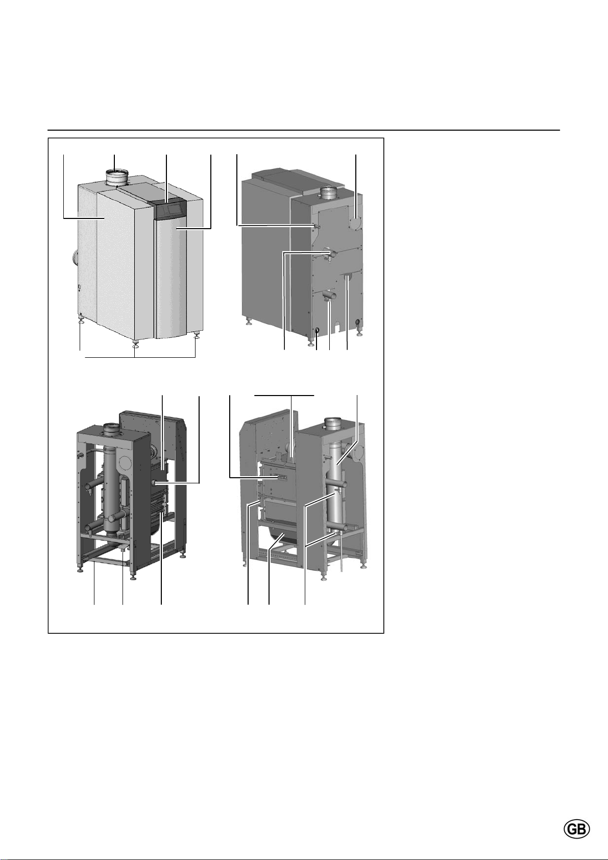
Layout of boiler
Operating principle
1 5 4 2 7 6
3 8 12 9 10
14 22 23 18, 19, 20, 21 25
Layout of boiler
The R600 boiler consists of the following main components:
1 Casing
2 Front panel
3 Adjustable feet
4 Control panel (below cover)
5 Flue gas connection
6 Air intake connection
(under casing)
7 Gas connection
8 Flow water connection
9 Return water connection
10 2nd (hot) return water connection
(for split system use), accessory
11 Filling/draining valve
12 Electrical input connections
13 Frame
14 Burner/1st heat exchanger
assembly
15 2nd/3rd heat exchanger assembly
16 Water headers
17 Condensate receptacle
18 Whirlwind gas/air mixing system
19 Fan
20 Gas valve
21 Gas pressure switch
22 Sight glass
23 Ignition and ionisation electrodes
24 Syphon
25 Removable flue gas adapter
13 24 15 16 17 11
Operating principle
The R600 is a fully modulating boiler.
The control unit of the boiler adapts the
modulation ratio automatically to the
heat demand requested by the system.
This is done by controlling the speed of
the fan. As a result, the Whirlwind mixing system will adapt the gas ratio to
the chosen fan speed, in order to maintain the best possible combustion figures and therewith the best efficiency.
The flue gases created by the combustion are transported downwards
through the boiler and leave at the back
side into the chimney connection.
5
The return water from the system enters the boiler in the lower section,
where is the lowest flue gas temperature in the boiler. In this section condensation takes place. The water is
being transported upwards through the
boiler, in order to leave the boiler at the
top (burner) section. The cross flow
working principle (water up, flue gas
down) ensures the most efficient combustion results.
The LMS14 control unit can control the
boiler operation based on:
Boiler control (stand alone operation);
weather compensated operation
(with optional outdoor sensor);
with 0-10V external influence
(temperature or capacity) from a building management system.
Page 6
Technical data
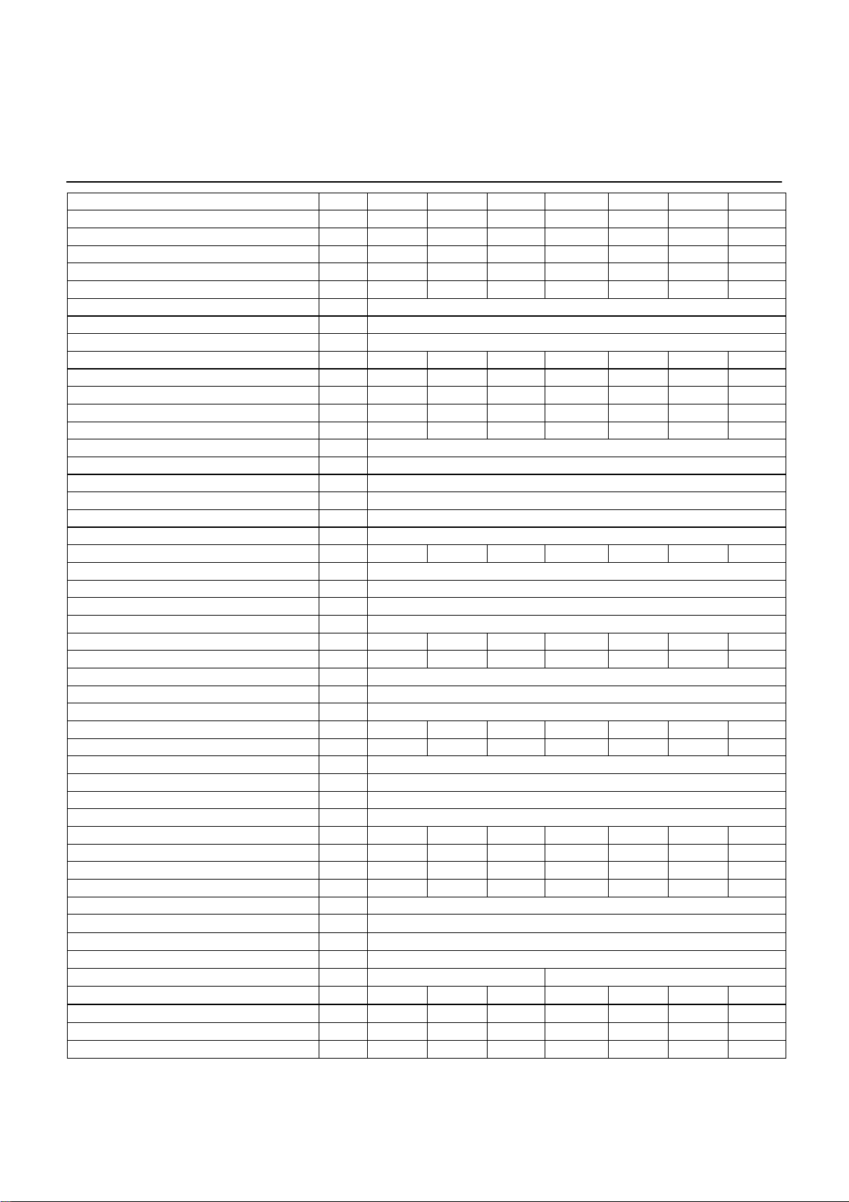
R601 R602 R603 R604 R605 R606 R607
Nominal heat output at 80/60ºC max/min*
Nominal heat output at 75/60ºC max/min*
Nominal heat output at 40/30ºC max/min*
Nominal heat input Hi max/min*
Efficiency at 80/60ºC
Efficiency at 40/30ºC
Annual efficiency (NNG 75/60ºC)
Annual efficiency (NNG 40/30ºC)
Standstill losses (T
Max. condensate flow
Gas consumption G20 max/min (10,9 kWh/m
Gas consumption G25 max/min (8,34 kWh/m
Gas consumption G31 max/min (12,8 kWh/kg)
Gas pressure G20
Gas pressure G25
Gas pressure G31
Maximum gas pressure
Flue gas temperature at 80/60ºC max/min
Flue gas temperature at 40/30ºC max/min
Flue gas quantity max/min*
CO
level natural gas G20/G25 max/min % 10.2/9.4
2
level G31 max/min % 11.9/10.0
CO
2
NOx level max/min
CO level max/min
Max. permissible flue resistance max/min
Water volume
Water pressure max/min
Max. water temperature (High limit thermostat)
Maximum temperature setpoint
Nominal water flow at dT=20K
Hydraulic resistance at nominal water flow
Electrical connection
Frequency
Mains connection fuse
IP class
Power consumption boiler max/min (excl. pump)
Power consumption speed controlled pump (opt)
Power consumption bypass pump (optional)
Weight (empty)
Noise level at 1 meter distance dB(A) 59
Ionisation current minimum µA 6
PH value condensate - 3.2
CE certification code - CE-0063BS3840
Water connections
Gas connection
Flue gas connection
Air intake connection (for room sealed use)
Condensate connection
Hz 50
- IP20
% 98.0 98.0 98.0 98.0 99.1 99.1 99.1
% 103.7
= 70ºC) % 0.21 0.18 0.17 0.16 0.15 0.14 0.13
water
l/h 11 15 19 22 30 37 42
mbar 20
mbar 25
mbar 30/50
mg/kWh 35/15
mg/kWh 14/8
l 27 31 35 61 68 75 82
V 230/400
A 16
kg 295 345 400 465 535 590 650
- R2" DN65 PN16
- R3/4" R1" R1" R1" R1.1/2" R1.1/2" R1.1/2"
mm 150 150 200 200 250 250 250
kW 145.0/24.5 194.0/41.5 242.0/41.5 291.0/41.5 388.0/80.5 485.0/80.5 550.0/80.5
% 106.8
% 110.4
mbar 50
m
bar 8/1
ºC 90
m
mm 40 40 40 40 40 40 40
kW 142.1/24.0 190.1/40.6 237.2/40.6 285.2/40.6 384.5/79.6 480.6/79.6 545.1/79.6
kW 142.2/24.0 190.3/40.6 237.4/40.6 285.5/40.6 384.9/79.7 481.1/79.7 545.6/79.7
kW 150.4/25.5 201.2/43.1 251.0/43.1 301.8/43.1 402.4/83.6 502.9/83.6 570.4/83.6
3
) m3/h 13.3/2.3 17.8/3.8 22.2/3.8 26.7/3.8 35.6/7.4 44.5/7.4 50.5/7.4
3
) m3/h 17.4/2.9 23.2/5.0 29.0/5.0 34.9/5.0 46.5/9.7 58.2/9.7 66.0/9.7
kg/h 11.3/1.9 15.2/3.2 18.9/3.2 22.7/3.2 30.3/6.3 37.9/6.3 43.0/6.3
ºC 78/61
ºC 56/30
3
/h 238/40 318/69 397/69 477/69 636/134 795/134 901/134
Pa 160/10 160/10 200/10 200/10 200/10 250/10 250/10
ºC 100
3
/h 6.1 8.1 10.2 12.2 16.3 20.4 23.1
kPa 10 18 28 15 27 42 55
W 158/43 200/35 230/35 260/35 470/61 650/61 770/61
W 190/9 190/9 310/12 310/12 470/25 590/25 800/38
W 190/9 190/9 190/9 190/9 190/9 310/12 310/12
mm 130 150 150 150 200 200 200
* min load on gasses G20, G25, G31. For type R602-R607 on gasses G25 (LL)-Gas min value is 15% higher.
6
Page 7
Technical data
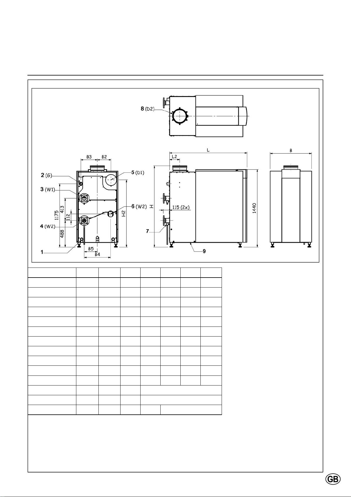
Dimension R601 R602 R603 R604 R605 R606 R607
L mm 1105 1260 1470 1220 1435 1585 1735
L2 mm 127.5 127.5 137.5 137.5 187.5 187.5 187.5
H mm 1480 1480 1500 1500 1500 1500 1500
H2 mm 1120 1130 1130 1150 1245 1245 1245
B mm 670 670 670 770 770 770 770
B2 mm 225 235 235 235 215 215 215
B3 mm 260 260 260 310 310 310 310
B4 mm 260 260 260 490 490 490 490
B5 mm 130 130 130 245 245 245 245
D1 mm (Diam.) 130 150 150 150 200 200 200
D2 mm (Diam.) 150 150 200 200 250 250 250
W1 R" / DN R2" R2" R2" DN65 PN16
W2 R" / DN R2" R2" R2" DN65 PN16
G R R 3/4" R 1" R 1" R 1" R 1 1/2"
1 Electrical connections
2 Gas supply
3 Water supply
4 Water return (Cold)
5 Air Intake (under casing)
6 Water 2nd return (optional)
7 Boiler water drain valve 1/2"
8 Flue gas Outlet
9 Condensate drain
flexible hose 25mm diam.
7
Page 8
Extent of delivery
Standard boiler
Accessories
Standard boiler
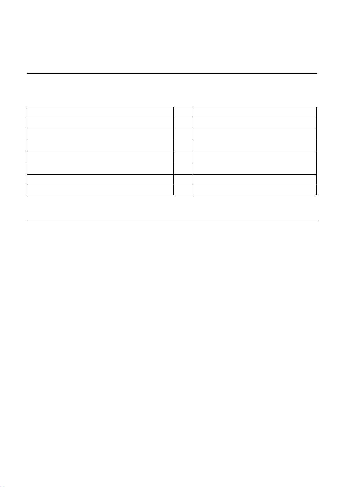
A boiler delivery package contains the
following components:
Component Pcs. Package
Boiler fully assembled and tested 1 Mounted on wooden blocks with wooden border,
sealed in PE foil
Adjustable feet 4 Mounted on frame of the boiler
Syphon for condensate connection 1 Cardboard box on top of heatexchanger
(under casing)
Conversion kit for natural gas L and propane incl. instruction 1 Cardboard box on top of heatexchanger
(under casing)
Operation and Installation manual 1 Map attached to back panel of the boiler
Spare parts list 1 Map attached to back panel of the boiler
Wiring diagram 1 Map attached to back panel of the boiler
Accessories
Additional to the boiler, the following
accessories can be ordered:
Standard 3-step pump incl. connec-
tion kit;
Speed controlled pump incl. connec-
tion kit;
Safety valve, manometer and de-
aerator (3,4,5 or 6 bar) incl. connection kit;
2x max. water pressure switch and 1
external high limit thermostat incl.
connection kit;
Gas filter incl. connection kit;
Max. gas pressure switch;
External high limit thermostat incl.
connection kit;
Gas valve leakage tester (not possi-
ble for R601);
2nd Return connection for
Split System use;
Controlled bypass (incl. pump) incl.
connection kit;
Plate heat exchanger (dT=10K/15K or
dT=20K) incl. connection kit;
Low velocity header, suitable for
dT=10K/15K and dT=20K incl. connection kit;
Duo header for connecting 2 boilers
in cascade (excl. connection kit);
Extension module AVS75 for heating
zone control or external gas valve
and/or room fan control.
For each boiler a maximum of 3
AVS75 modules (2x heating zone, 1x
ext. gas valve / room fan) can be integrated in the boiler;
Additional RVS63 heating zone con-
troller, when controlling more than 2
zones (incl. wall hung box, all necessary sensors and sockets and connection material for bus communication).
The above accessories are specially
designed for the R600 boiler and therewith easy to install (plug and play). By
choosing a combination of the kits mentioned above, you can create your own
complete system solution. Ask your
supplier for more detailed information.
8
Page 9
Installation
Boiler transport
1
2
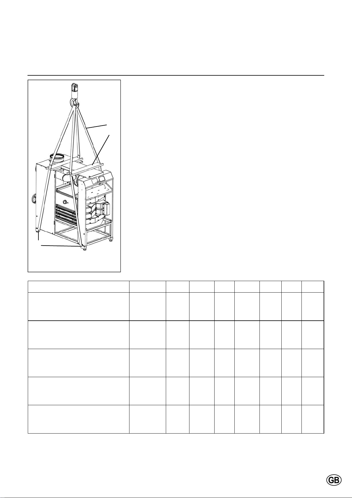
Boiler transport
The R600 boiler will be supplied as a
complete unit being fully assembled
and pre-tested. The maximum width is
670mm for models R601-R603 and
770mm for models R604-R607, which
makes it possible to transport all models through a normal door in one piece. The boiler can be transported with a
pallet truck, entering either from the
front or from the side.
Whenever necessary, the boiler can be
dismantled into smaller parts for easier
transport inside the building. The table
below shows the main dismantled parts
with their weight and dimensions.
When the boiler has to be transported
with a crane, it is necessary to remove
the casing before connecting the boiler
to the crane. Always connect the crane
to the frame of the boiler by using
straps.
3
1 Hoisting belt (4x)
2 Wooden retaining beam (2x)
3 Hoisting belt position (4x)
Component R601 R602 R603 R604 R605 R606 R607
Burner/1st heat exchanger assembly Weight [kg]
Length [mm]
Width [mm]
Height [mm]
2nd/3rd heat exchanger assembly Weight [kg]
Length [mm]
Width [mm]
Height [mm]
Condensate receptacle
Frame
Front U-frame with electronic board Weight [kg]
Weight [kg]
Length [mm]
Width [mm]
Height [mm]
Weight [kg]
Length [mm]
Width [mm]
Height [mm]
Length [mm]
Width [mm]
Height [mm]
86
735
400
321
90
735
400
244
7
589
385
225
15
990
624
335
11
628
1304
202
100
885
400
321
103
885
400
244
9
739
385
225
16
1140
624
335
11
628
1304
202
112
1035
400
321
116
1035
400
244
10
889
385
225
17
1350
624
335
11
628
1304
202
135
735
680
321
150
735
680
244
11
589
665
225
17
1100
724
335
12
728
1304
202
158
885
680
321
170
885
680
244
12
739
665
225
18
1320
724
335
12
728
1304
202
181
1035
680
321
198
1035
680
244
13
889
665
225
19
1470
724
335
12
728
1304
202
198
1185
680
321
219
1185
680
244
15
1039
665
225
21
1620
724
335
12
728
1304
202
9
Page 10
Installation
Removing the casing
1.
Boiler transport
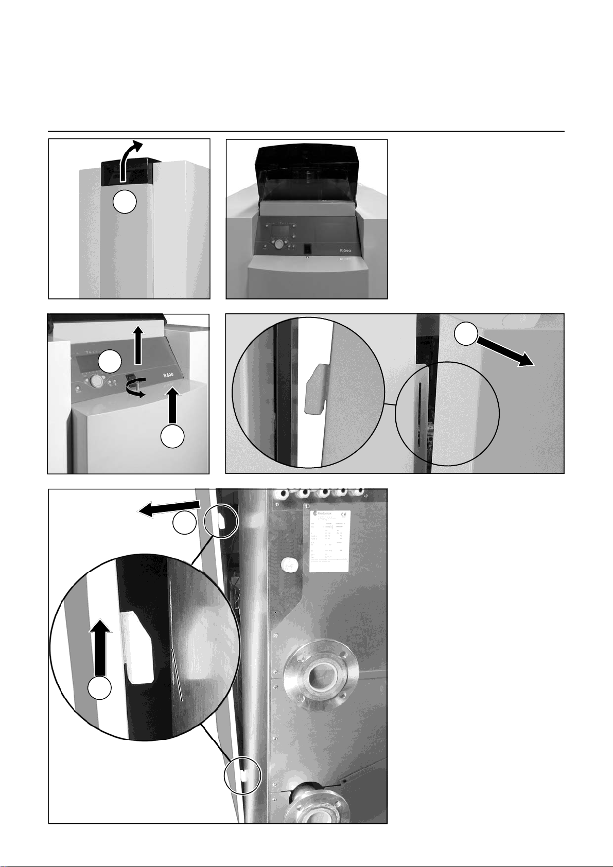
Remove the casing before transporting
the boiler, in order to avoid damage to
the casing parts during transportation.
Removing the casing is done as follows:
4.
2.
3.
6.
5.
10
Page 11
Installation
Boiler installation
Boiler installation
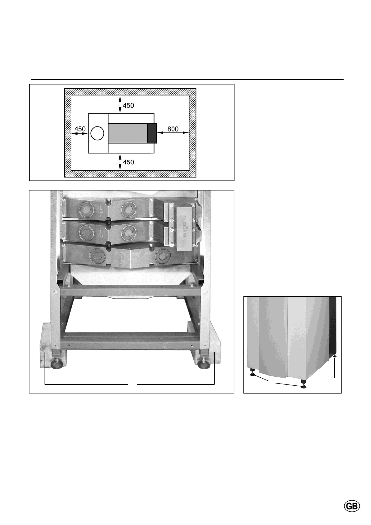
The boiler should be positioned in a
frost-proof boiler room. If the boiler
room is on the roof, the boiler itself may
never be the highest point of the installation.
When positioning the boiler, please
note the recommended minimum clearance in the picture. When the boiler is
positioned with less free space, maintenance activities will be more difficult.
Once the boiler is in the correct position, the wooden blocks (1) should be
removed and the adjustable feet (2)
(with vibration absorption dampers)
should be adjusted to the right height.
Water and gas connections should be
done after mounting the feet, as they
affect the exact height of all connections.
1
11
2 2
Page 12
Installation
Connecting the boiler
1 3
4 5 6
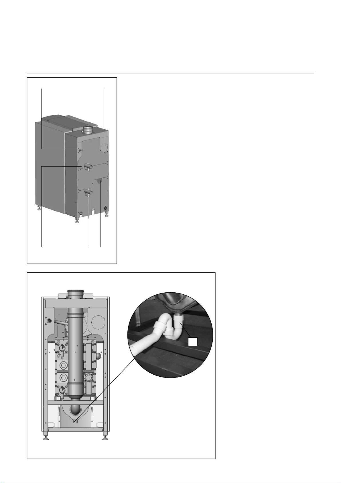
Connecting the boiler
This chapter will explain how to make
all connections to the boiler with regard
to:
Hydraulic connections
Condensate drain connection
Gas connection
Flue gas connection
Air intake connection
(under casing)
Electrical connection
The boiler should always be connected
in such a way, that the system applies
to all relevant standards and regulations (European, national and local). It’s
the responsibility of the installer to ensure that all standards and regulations
are respected.
8
Hydraulic connections
The boiler should always be connected
in such a way, that water flow through
the boiler can be ensured at all times.
Connect the flow (4) and return (5) connection of the system tension free to
the boiler connections.
The (optional) 2nd return kit allows the
boiler to be used in a system with two
return circuits. The common return
becomes the low temperature return,
the 2nd return connection (6) is the
high temperature return.
The (optional) accessory kit with
safety valve, manometer and deaerator
should be mounted on the flow
connection (4) of the boiler, before
connecting to the system.
The (optional) pump kit should be
mounted directly to the return
connection (5) of the boiler, before
connecting to the system.
Condensate connection (8)
After filling with water, the syphon
(included in delivery) should be installed to the connection at the bottom
of the condensate receptacle. Lead the
hose under the frame at the back of the
boiler and connect it to the draining
system in the boiler room. The connection to the draining system should always be done with an open connection,
in order to avoid a flooding of the boiler
in case of a blocked drain.
12
Page 13
Installation
Connecting the boiler
1 7 3
2
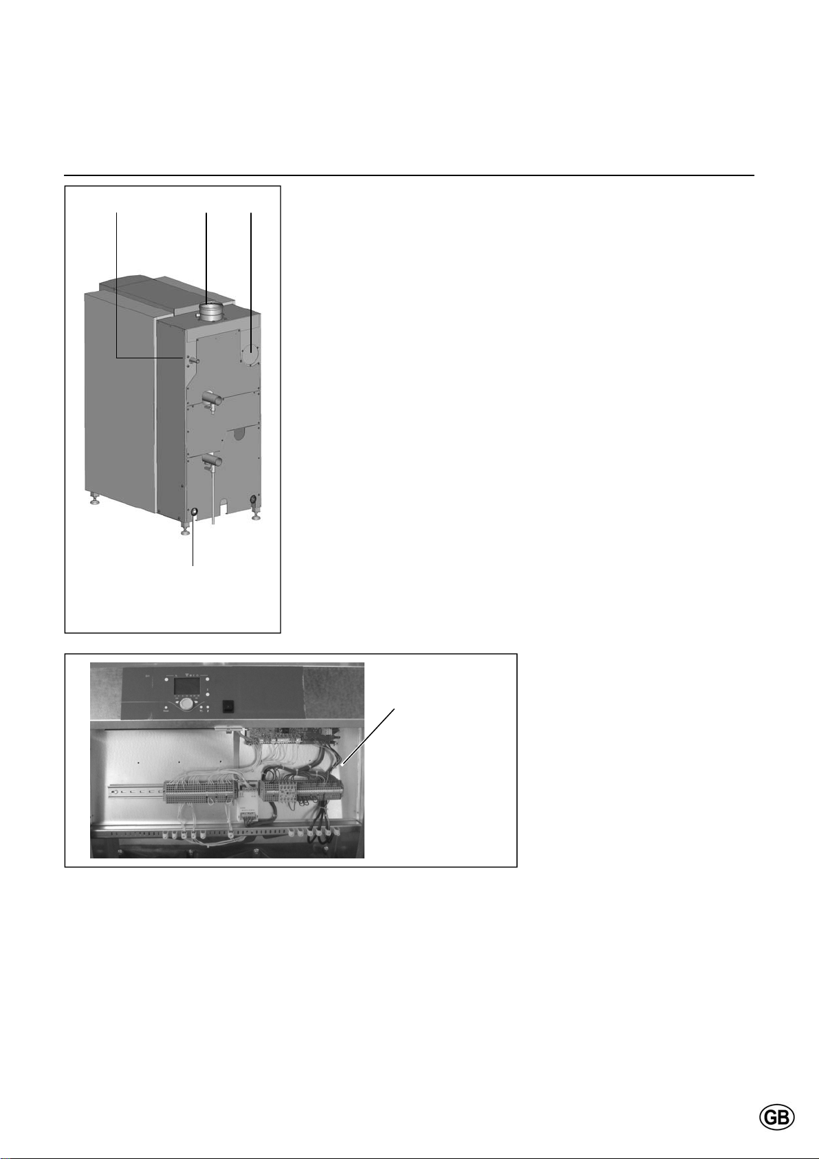
Gas connection (1)
The gas connection must be made by
an authorized installer in accordance
with the applicable national and local
standards and regulations.
Connect the gas line from the system
tension free to the gas connection (1) of
the boiler. A gas cock should be
mounted directly behind the boiler.
A gas filter can be mounted directly on
the gas connection of the boiler.
Flue gas connection (7)
Regulations for the construction of flue
gas systems are very different for each
country. It should be ensured that all
national regulations with regard to flue
gas systems are respected.
Connect the flue gas system to the flue
gas connection (7) of the boiler, use
fluegas systems with seamless connections only. It’s not necessary to make a
separate condensate drain for the flue
gas system, as the condensate will be
drained via the syphon of the boiler.
Please note the following issues:
It’s recommended to use stainless
steel or PPS fluegas systems
The diameter of the flue gas system
must be chosen by calculation according to the national regulations
Construct the flue gas system as
short as possible (for maximum
length see planner documentation)
Construct horizonal ways with a mini-
mum angle of 3º
Air intake connection (3)
The air intake can be connected in case of room sealed installation. The cover (3) must be disassembled in order
to connect the air intake piping to the
connector inside the boiler. The diameter should be calculated according to
the national regulations, together with
the flue gas system. The total resistance of both systems should never overcome the maximum permissible resistance of the fan inside the boiler (see
also chapter: Technical data).
Electrical connection
The electrical connection must be made by an authorized installer in
accordance with the applicable national
and local standards and regulations.
For the power supply it’s necessary to
use a mains isolator switch with a contact opening of at least 3 mm
within the boiler room. This switch can
be used to switch off the power supply
for maintenance purposes.
11
All cables should be lead through the
cable glant (2) from the back of the
boiler boiler into the electro panel
(11).
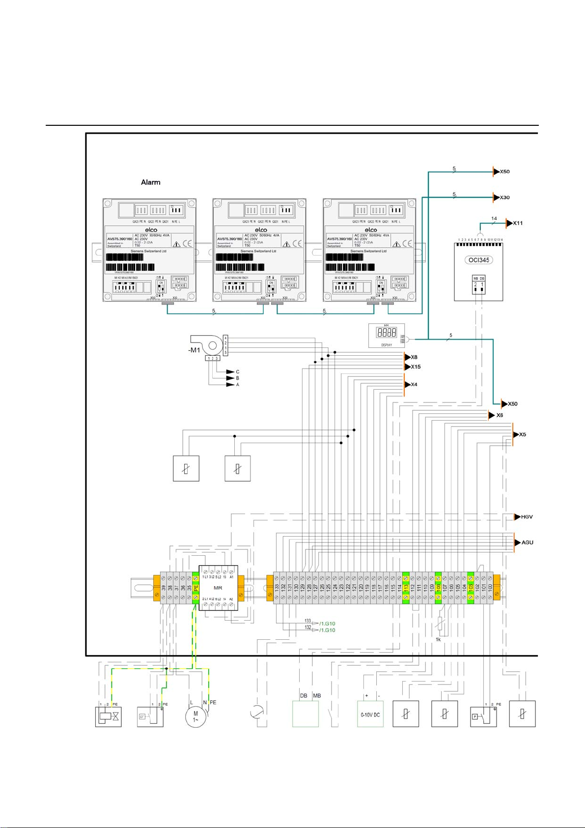
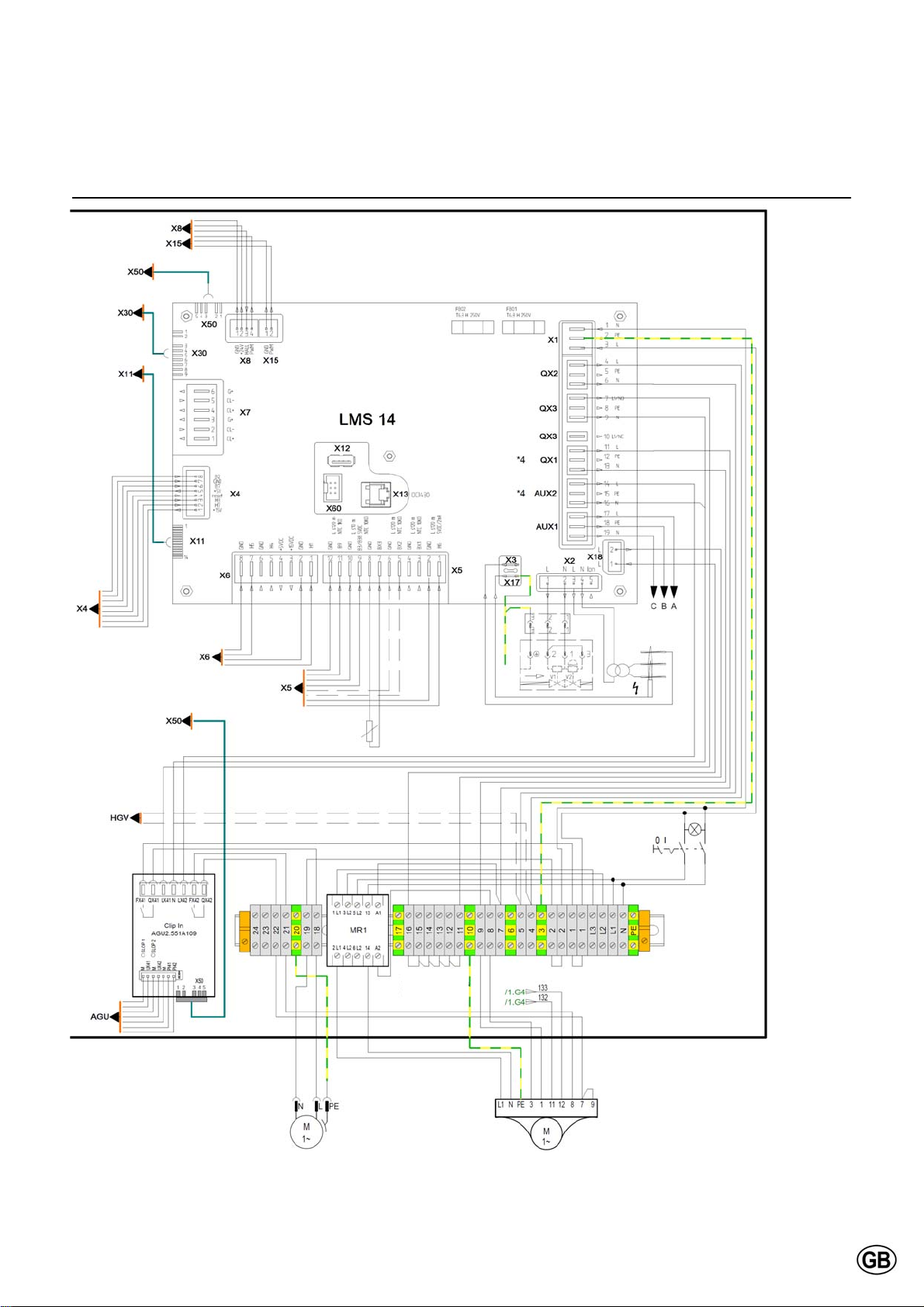
Connect all wires to the terminals
according to the wiring diagram of the
boiler (enclosed in map attached to
back panel of the boiler).
13
Page 14
Installation
Wiring diagram - Boiler
Heating circuit 2 Heating circuit 1
Return
temp. sensor
Flow
temp. sensor
Min. gas
Main gas valve
Pressure switch
Room fan
(2A max.)
Mod. feedback
0-10V DC
LPB Bus
Enable
Ext. Setpoint
0-10V DC
Outside
temp. sensor
DHW Thermostat
or
DHW temp. sensor
pressure switch
Common flow
temp. sensor
14
Page 15
Installation
Wiring diagram - Boiler
Flue gas
temp. sensor
Lockout
input
Boiler pump /
DHW Pump
230V~ (1A max.)
15
Bypass pump
Page 16
Installation
Wiring diagram - Accessories
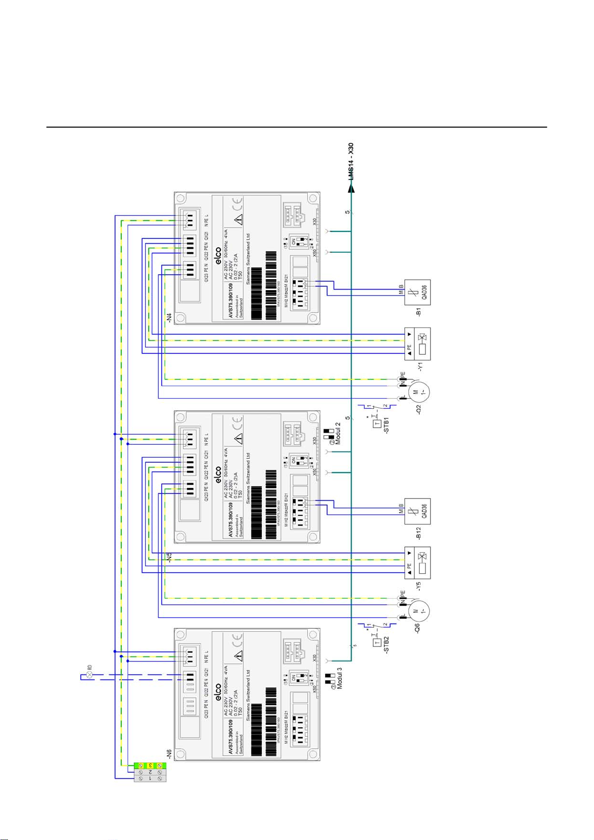
Heating circuit 1
Heating circuit 2
Flow temp. sensor
Mixing valve control
(0.5A max.)
Heating circuit pump
(2A max.)
Flow temp. sensor
Mixing valve control
(0.5A max.)
Heating circuit pump
(2A max.)
Alarm
16
Page 17
Installation
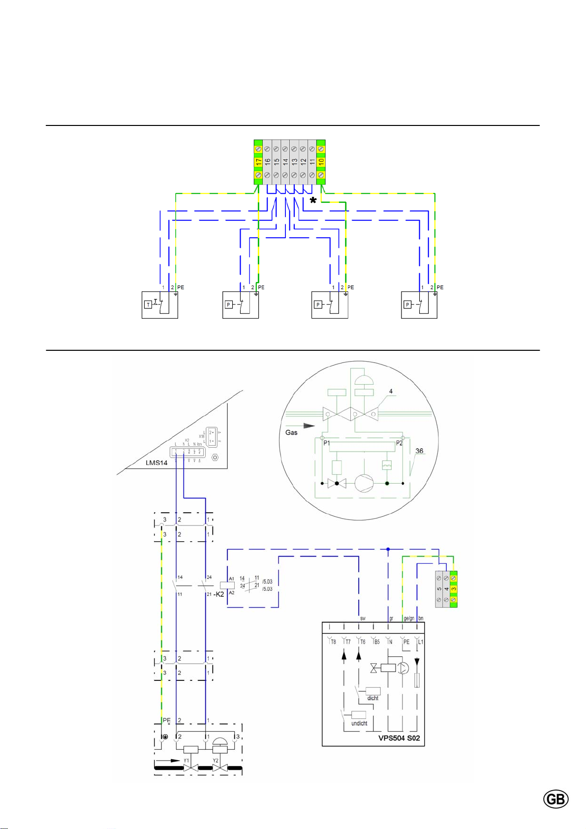
Wiring diagram - Accessories
* Remove jumper when connecting device
STL
Boiler temp.
Max. water
pressure switch
Max. water
pressure switch
Max. gas
pressure switch
Leakage test
Gas valve
17
Page 18
Commissioning
Water and hydraulic system
Commissioning of the boiler should be
carried out by authorized personnel
only. Failure to respect this condition
makes the guarantee void. A protocol
of the commissioning should be filled
out (see end of this chapter for example
of commissioning protocol).
Boiler output
[kW] [mol/m3] [ºdH] [ºf]
50 - 200 2.0 11.2 20
200 - 600 1.5 8.4 15
Max. sum of alkaline earths
This chapter explains the commissioning of the boiler with the standard boiler controller. When an additional system controller is installed, please refer
to its manual for commissioning the
controller.
Max. total hardness
Water quality
The system should be filled with water
with a PH value between 8,0 and 9,5.
The chloride value of the water should
not exceed 50 mg/l. Entry of oxygene
by diffusion should be prevented at all
times. Damage to the heat exchanger
because of oxygene diffusion will not
be taken under warranty.
In installations with higher water volumes, it’s necessary to respect the maximum filling and additional volumes with
corresponding hardness values as stated in the german VDI2035 standard. In
the table you can find the nominal values for filling and additional water for
the R600 according to the the VDI2035.
Concentrate
Ca(HCO3)2
3
ºf Maximum water (re)fill volume V
mol/m
0.5 5 - - - - - - -
1.0 10 - - - - - - -
1.5 15 3 4 5 6 8 10 12
2.0 20 3 4 5 6 6.3 7.8 9.4
2.5 25 1.9 2.5 3.1 3.8 5.0 6.3 7.5
3.0 30 1.6 2.1 2.6 3.1 4.2 5.2 6.3
ºdH
2.8
5.6
8.4
11.2
14.0
16.8
Capacity of installation Q (kW)
150 200 250 300 400 500 600
[m3]
max
Water pressure
Open the valves to the system. Check
the water pressure in the system. If the
water pressure is too low (see table
below), increase the pressure up to at
least the minimum required water
pressure in the table.
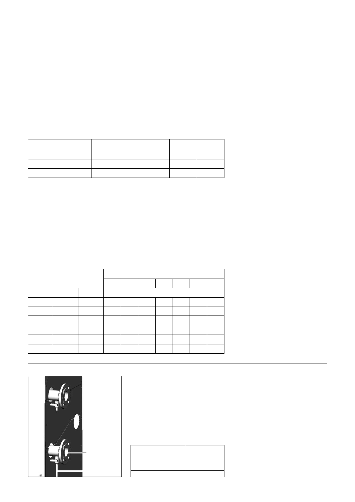
Filling can be done via the fill and drain
valve (2) on the return connection (1) of
the boiler.
The table at the left gives an indication
of the relation between the water quality and the maximum water filling volume during the lifetime of the boiler.
Consult the original text of the VDI2035
for more detailed information.
Hydraulic system
Check if the boiler is hydraulically connected to the system in such way, that
water flow can be secured at all times
during burner operation. The water flow
is supervised by dT-measurement
across the flow and return connections
of the boiler. A lack of water flow will
lead to a reduction of power and eventually a lockout of the boiler.
18
1
2
Minimum operating
pressure
[bar]
> 1.5 90
> 1.0 80
Flow tem-
perature
[ºC]
Page 19
Commissioning
Gas supply
Condensate connection
Flue and air intake connections
Gas supply
Check the gas supply connection to the
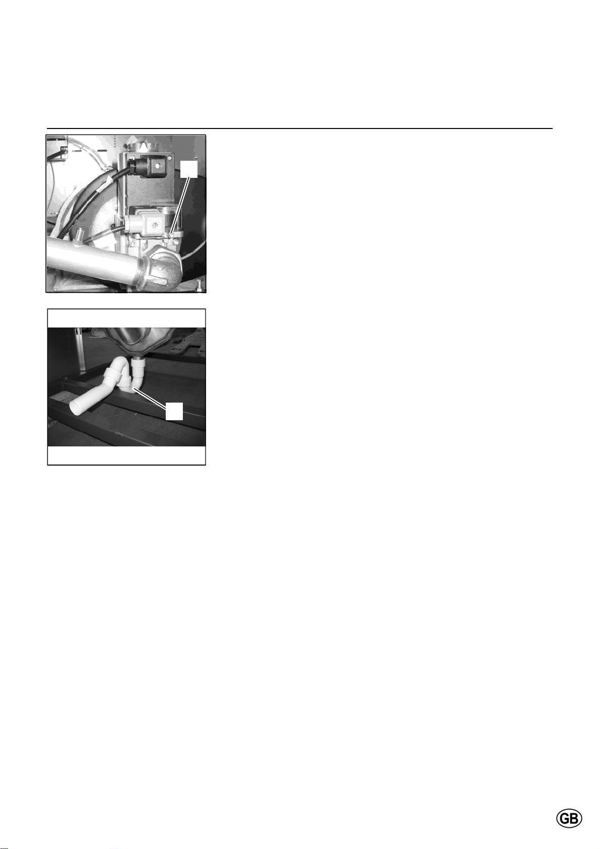
1
boiler for tightness. If any leakage is
found, reseal the leakage before starting the boiler!
Remove any air between the gas valve
and the gas line. This can be done at
the test point (1) at the gas pressure
switch. Don’t forget to close the test
point afterwards!
Check the gas type and values with the
local gas company, in order to know for
which gas type the boiler should be
commissioned.
Consult the conversion kit instruction if
the boiler is to be installed with natural
gas L or LPG.
Condensate connection
Remove the syphon (2) from the condensate connection. Fill it with water
and place it back in the original position. Make sure the syphon is filled
2
before starting the boiler, in
order to prevent flue gases discharging through the condensate connection!
Flue and air intake connections
Check whether the flue and air intake
systems are made according to the
national and local regulations. Installations which don’t comply with the regulations, are not allowed to be commissioned.
Make sure that all connections are free.
The size of flue gas and air intake con-
nections may not be reduced.
19
Page 20
Commissioning
Prepare boiler for first startup
M
H
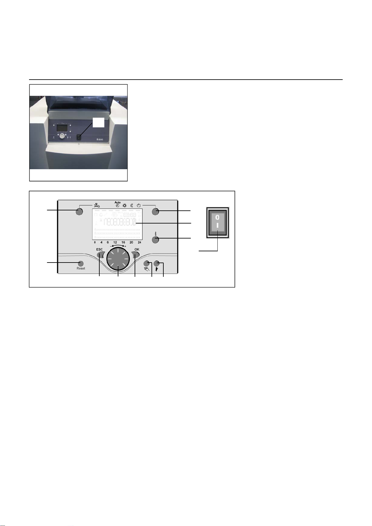
Legend:
A On/off switch
B Return (ESC)
C Room temperature control
A
B C D E F
D Confirmation (OK)
E Manual mode
F Chimney sweeper mode
G Info mode
H Reset button
I Operation mode heating zone(s)
L Display
M Operation mode DHW
I
L
G
A
Preparation for first startup
Open the gas supply;
Enable the power supply to the boiler;
Switch on the boiler with the on/off
switch (A);
Make sure the boiler is in standby
mode (K);
Check the pump operation: make
sure the pump runs in the right
direction;
Release all air from the pump motor.
It‘s recommended to put the boiler on
50% load after the first startup, as this
is the best starting point to do a proper
combustion analysis. This can be done
with the following procedure:
Push button I >3 Sek, the boiler goes
into controller Stopp mode.
Push the Info button (G), the actual
boiler load (%) appears in the display;
Choose „set up“ (confirm with OK
button), now the boiler load can be
changed by rotating the wheel (C)
and confirming the 50% setting with
the OK button.
After checking the combustion values
(see next page), the controller Stopp
mode can be stopped by pushing the
control mode button (I) >3 Sek.
20
Page 21
Commissioning
Combustion analysis
1
R601
2
4
R602 - R607
2
4
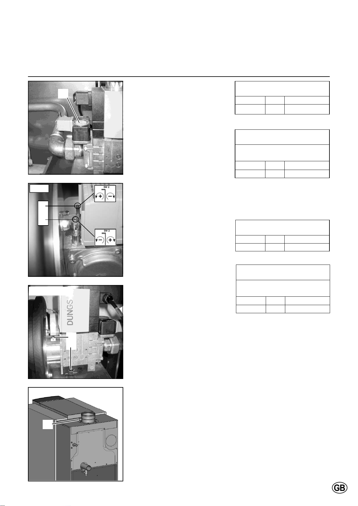
Combustion check at full load
Start the boiler in controller stop mode
and go to 50% load. Now the boiler
operates at 50% load. Allow the boiler
to stabilise the combustion for 3
minutes. Then increase the boiler load
step by step up to 100%. Check the
gas pressure on the inlet of the gas
valve while increa-sing the boiler load:
the gas pressure should never go
below the minimum required value
see technical data. Set the minimum
gas pressure switch (1) at 75% of the
required gas pressure.
Check the combustion settings via the
test point in the chimney connection(3).
If necessary, correct the settings with
the flat adjustment screw on the outlet
of the gas valve (2).
Combustion check at minimum load
Switch the boiler to minimum load (0%).
Check the combustion settings the
same way as described for full load. If
necessary, correct the settings with the
allen key adjustment screw on either
side of the gas valve (4).
Combustion check at 50% load
An additional reference check of combustion values at 50% load is recommended in order to check if the gas
valve is set in such way, that the modulating behaviour is normal. The CO
value should be in between the settings
of full load and minumum load. CO
value should be equal to full load and
minimum load values.
Make sure that the boiler is set to automatic operation and controller stop mode is disabled after the combustion test
is finished.
2
Combustion settings
for natural gas G20 / G25
R601-R607
CO
R601-R607
CO
R601-R607
CO
% 10.2 ± 0.2
2, max
Combustion settings
for LPG G31
Convert boiler before operation
(see coversion kit instruction)
% 11.9 ± 0.2
2, max
Combustion settings
for natural gas G20 / G25
% 9.4 ± 0.2
2, min
Combustion settings
for LPG
Convert boiler before operation
(see coversion kit instruction)
R601-R607
CO
% 10.0 ± 0.2
2, min
G31
3
21
Page 22

Commissioning
Check water flow
Check water flow
The water flow through the boiler can
be checked with two different methods
shown below.
∆T measurement
Check the temperature difference over
the boiler (T flow-return) when the
boiler is running on 100% load. The
nominal T is 20K and must be at least
between 15K and 25K for secure boiler
operation. An indication of the actual
flow rate can be found with the following calculation (see table below for
nominal data):
q
actual
= (T
nominal
/ T
measured
) * q
nominal
[m3/h]
∆p measurement
Check the pressure difference over the
boiler (p flow-return) when the boiler
pump is running (burner on is not required). The nominal p for each boiler
type can be found in the table below,
actual p must be within:
0.64*p
P 1.77*p
nom
nom
. An
indication of the actual flow rate can be
found with the following calculation (see
table below for nominal data):
q
actual
= (p
measured
/ p
nominal
) * q
nominal
[m3/h]
Water flow data
R601 R602 R603 R604 R605 R606 R607
Nominal flow rate [m
3
/h] 6.1 8.1 10.2 12.2 16.3 20.4 23.1
T at nominal flow rate [ºC] 20
p at nominal flow rate [kPa] 10 18 28 15 27 42 55
22
Page 23
Commissioning
Check functionality of safety devices
Gas tightness check
Boiler shut down
1 2 3
5
4
6
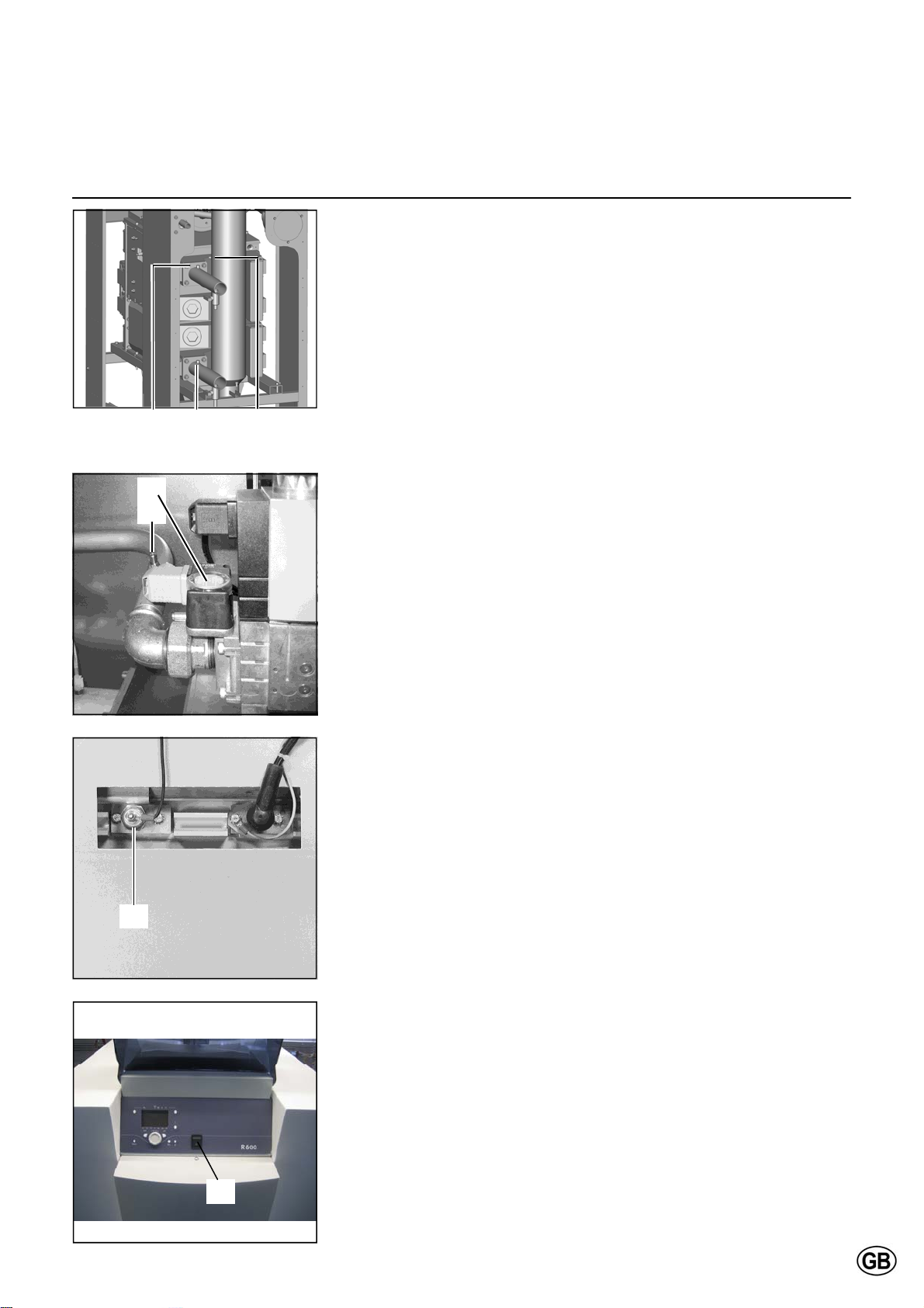
Check functionality of safety devices
All safety devices have to be checked
on good functioning. Safety devices on
a standard boiler are a water flow temperature sensor, fluegas temperature
sensor, minumum gas pressure switch
and ionisation electrode. These devices
can be checked as described below.
Flow temperature sensor (1)
Disconnect the plug from the sensor
while the boiler is switched on. This
should result in a lockout no. 20.
The lockout should disappear as soon
as the plug is placed back in position,
the boiler will restart.
Return temperature sensor (2)
Disconnect the plug from the sensor
while the boiler is switched on. This
should result in a lockout no. 40.
The lockout should disappear as soon
as the plug is placed back in position,
the boiler will restart.
Flue gas temperature sensor (3)
Disconnect the plug from the sensor
while the boiler is switched on. This
should result in a lockout no. 28.
The lockout should disappear as soon
as the plug is placed back in position,
the boiler will restart.
.
Minimum gas pressure switch (5)
Close the gas cock when the boiler is in
standby position (
point on the gas line (4) while measuring the gas pressure on the test point
of the gas pressure switch (5).
The boiler will go in lockout no. 2 when
the switch off setting is achieved. Close
both test points and open the gas cock.
K). Open the test
Ionisation electrode (6)
Remove electrical connection from the
ionisation electrode while the boiler is
running, the boiler will go in lockout no.
128. The boiler will try to restart. With
the electrical connection removed, the
restart will result in lockout no. 133.
When the connection is already mounted, the restart will be successful.
Measuring the ionisation current can
be done by mounting a multi-meter (set
to µA) in between the ionisation electrode and its electrical connection. The
ionisation current should always be
above 1.2 µA, in normal conditions it
will be 6 µA and above.
Gas tightness check
Check the gas tightness of all sealed
connections with an approved soap or
electronic gas analyzer, for example:
Test points
Bolt connections
Gaskets of mixing system, etc.
Boiler shut down
When the boiler will not be used for
longer periods, shut down the boiler by
following procedure:
Switch the boiler in standby operation
(K)
Switch off the boiler with the on/off
switch (7)
Disable power supply to the boiler by
deactivating the mains isolator switch
in the boiler room
Close the gas supply to the boiler.
7
23
Page 24
Commissioning
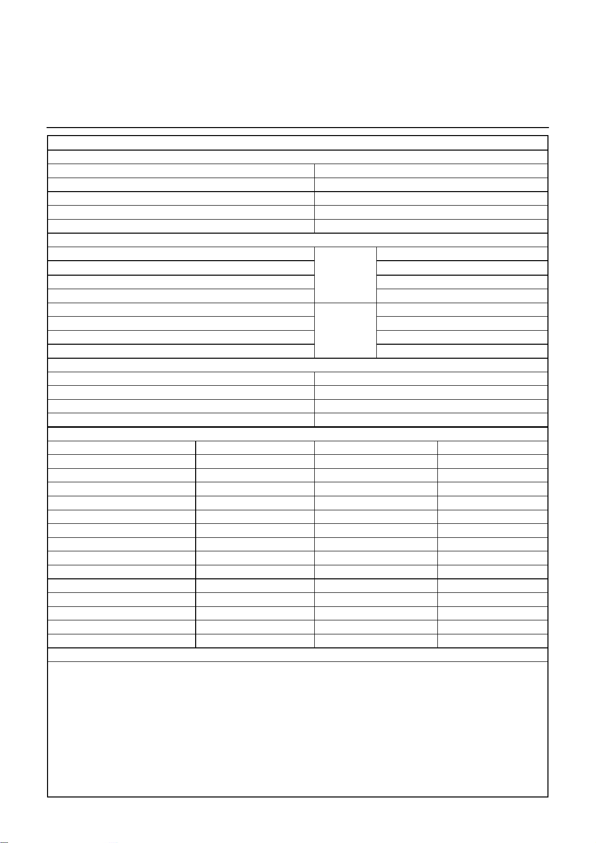
Commissioning protocol
Commissioning Protocol R600
Project
Boiler type Project
Serial number Address
Year City
Nominal load (Hi) [kW] Date
Nominal output (Hi) [kW] Engi neer
System
Water pressure [bar] InstallatiWater pH [-] Ground floor
on:
Roof top
Water hardness [dºH] Basement
Water chloride [mg/l] Other: .........................
Water T full load [ºC] HydrauWater p
[kPa] Plated heat exchanger
boiler
Water flow [m
lics:
3
/h] Bypass boiler
Low velocity header
Pump setting [-] Other: .........................
Safety devices
High limit setting [ºC] Water flow sensor checked
Temp. limiter setting [ºC] Fluegas sensor checked
Min. gas pressure switch setting [mbar]
Ignition time burner [sec]
Combustion analysis
Gas consumption [m
100% load 50% load Min. load
3
/h] [m3/h] [m3/h]
Gas pressure [mbar] [mbar] [mbar]
CO
[%] [%] [%]
2
O
[%] [%] [%]
2
CO [ppm] [ppm] [ppm]
NOx [ppm] [ppm] [ppm]
T
atmospheric
T
fluegas
T
water, flow
T
water, return
[ºC] [ºC] [ºC]
[ºC] [ºC] [ºC]
[ºC] [ºC] [ºC]
[ºC] [ºC] [ºC]
Ionisation current [µA] [µA] [µA]
p
[mbar] [mbar] [mbar]
fan
p
[mbar] [mbar] [mbar]
top panel
p
combustion chamber
[mbar] [mbar] [mbar]
Remarks
24
Page 25
Operating instructions
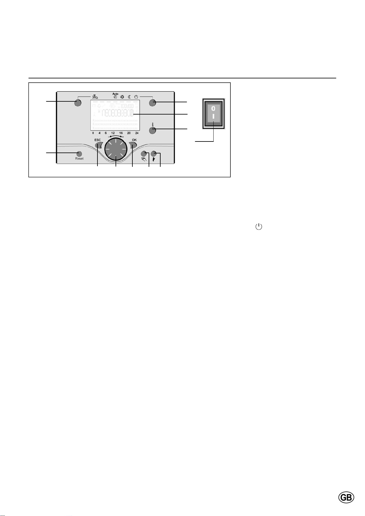
Controls
M
H
B C D E F
I
L
G
A
Legend:
A On/off switch
B Return (ESC)
C Room temperature control
D Confirmation (OK)
E Manual mode
F Chimney sweeper mode
G Info mode
H Reset button
I Operation mode heating zone(s)
L Display
M Operation mode DHW
Operation mode DHW (M)
For switching on the DHW operation
(indication in display below DHW symbol)
Operation mode heating zone(s) (I)
For setting 4 different heating modes:
Auto (clock): Automatic operation by
time programm
Comfort (sun): 24/7 heating in comfort
mode
Reduction (moon): 24/7 heating in
reduced mode
Standby: heating off, frost protection
activated.
Display (L)
Info mode (G)
Display possibility of following info
without influence on boiler control:
temperatures, operation mode
Heating / DHW, error code.
Room temperature control (C)
for changing room comfort tempe-
rature
for changing settings when pro-
gramming.
Confirmation (OK) (D)
Return (ESC) (B)
These buttons are used for programming in combination with the wheel.
By pressing the ESC button it‘s possible
to go back one level, changed values
are not taken over by the controller.
By pressing the OK button it‘s possible
to arrive in the next level or confirm
changed values.
Manual mode (E)
This button is used for switching the
boiler into manual mode. In manual mode all pumps will run and the mixing
valves are no longer controlled, the burner setpoint is 60°C (indicated by spanner symbol).
On/off switch (A)
Position 0:
Boiler and connected electrical components are no powered. Frost protection
is not secured.
Position I
The boiler and connected electrical
components are powered and standby
for operation.
Deaeration mode (E)
By pressing the manual mode button
longer than 3 seconds, the automatic
hydraulic deaeration is activated. During
deaeration the system is put in standby
mode
The pumps are switched on and off for
several times.
After deaeration, the boiler automatically
returns to normal operation.
Chimney sweeper mode (F)
Used for combustion analysis. By pressing the button once again, or automatically after 15 minutes, the chimney sweeper mode will be deactivated (indicated
by spanner symbol).
Reset button (H)
By shortly pressing the reset button a
burner lockout can be cancelled.
25
Page 26
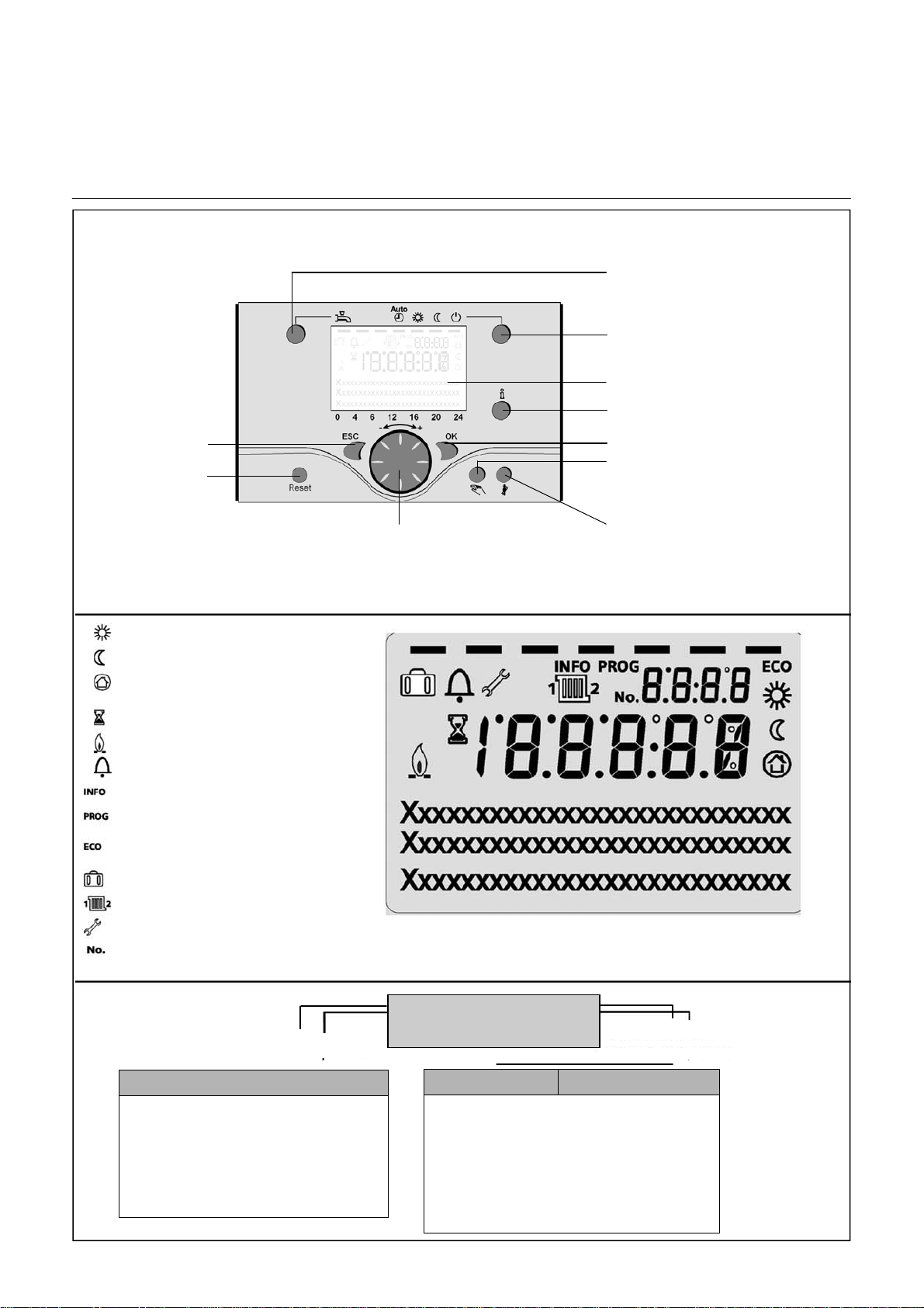
Operating instructions
Display / Programming
Quit menu
Reset
Select
(turn left/right)
DHW mode selection
Heating operation mode selection
(Controller Stopp mode when
pressing > 3 sec.)
Display
Info button
Confirm
Manual mode
(Deaeration mode when pressing
> 3 sec.)
Chimney sweeper mode
Heating to comfort setpoint Info level activated
Heating to reduced setpoint Programming activated
Heating for frost protection setpoint Heating temporarily
switched off
Process running – please weit ECO function active
Burner operating (only oil / gas boiler)
Error messages
Info level activated
Programming activated
Heating temporarily switched off
ECO function active
Holiday function active
Reference to heating circuit
Maintenance / special operation
Parameter number
Programming
Press OK (1x)
Enduser
- choose menu
- confirm with OK button
- choose parameter
- confirm with OK button
- change value + - with wheel
- confirm with OK button
- return to main menu with ESC button
- gewünschtes Menü
auswählen
- mit Taste OK bestätigen
- mit Taste ESC zurück
zur Grundanzeige
Default mode
(buttons)
Commissioning Expert
- choose user level
- confirm with OK button
- gewünschte Benutzer-Ebene auswählen
- choose menu
- mit Taste OK bestätigen
- confirm with OK button
- gewünschtes Menü auswählen
- choose parameter
- mit Taste OK bestätigen
- confirm with OK button
- mit Taste ESC zurück zur Grundanzeige
- change value + - with wheel
- confirm with OK button
- return to main menu with ESC button
Press OK (1x)
Press INFO (4 sec.)
26
Page 27
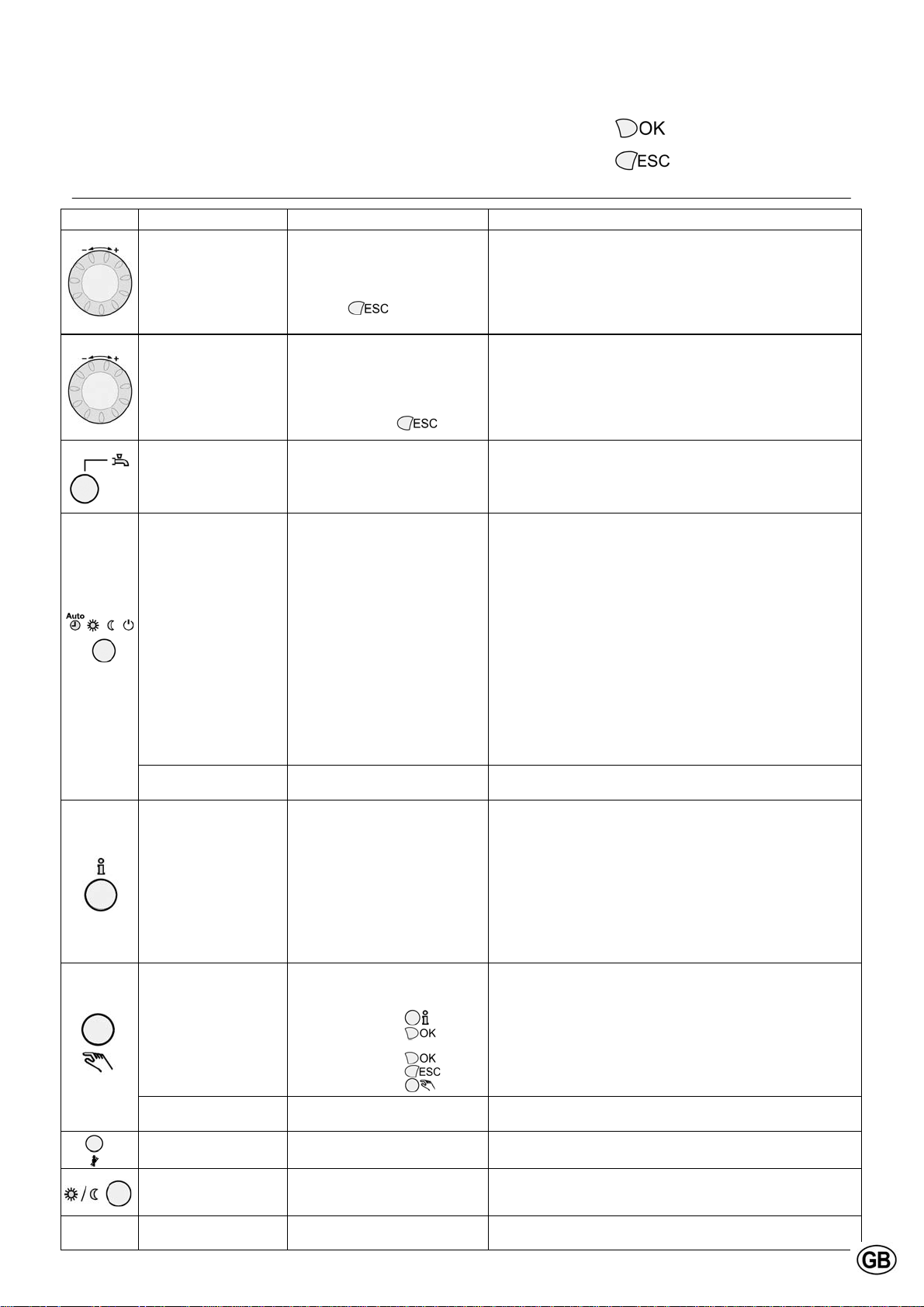
Operating instructions
Overview of main functions
Button Action Procedure Display / Function
Set room temperature
Zone 1 and zone 2
Actuate wheel left/right
Turn wheel
Confirm with OK button
or wait 5 sec.
or press
Comfort setpoint with blinking temperature
Blinking temperature in 0,5 °C steps from 10 to 30 °C
Comfort setpoint saved
Comfort setpoint cancelled
- after 3 sec. Main menu appears
= confirmation
= cancel, return to main
menu
Activate chimney sweeper
Temporary reduction of
RESET Reset button Press button (< 3 sec.)
Set room temperature for
zone 1 or zone 2
Switch on /off DHW operation
Change heating operation
mode
Controller Stop mode Press button > 3 sec.
Info display
Operation by manual
setpoint
Change factory setting
boiler temperature
Deaeration Press button > 3 sec.
mode
reduced temperature on
QAA75
Zone 2 independent from zone 1
Actuate wheel left/right
Confirm with OK button
Actuate wheel left/right
Confirm with OK button
or wait 5 sec.
or press
Press button DHW mode on / off
Factory setting
Press button 1x
Press button 1x again
Press button 1x again
Press button > 3 sec. again
Press button 1x
Press button 1x again
Press button 1x again
…..
Press button 1x
Press button 1x
Press button
Press button
Turn wheel -/+
Press button
Press button
Press button
Press button > 3 sec. again
Press button (< 3 sec.)
Press button again (< 3 sec.)
Press button
Press button again
Press button again > 3 sec.
Choose heating zone
Heating zone is chosen
Blinking temperature in 0,5 °C steps from 10 to 30 °C
Comfort setpoint saved
Comfort setpoint cancelled
- after 3 sec. Main menu appears
(see indication below DHW symbol)
- On: DHW mode by time programm
- Off: no DHW operation
- Safety functions activated
Automatic mode on, with:
- Heating by time programm
- Temperature setpoint by heating programm
- Safety functions activated
- Summer/Winter automatic switching activated
- ECO-functions activated
(see indication below operation symbol)
Continuous COMFORT heating on, with:
- Heating without time programm by comfort setpoint
- Safety functions activated
Continuous REDUCED heating on, with:
- Heating without time programm by reduced setpoint
- Safety functions activated
- Summer/Winter automatic switching activated
- ECO-functions activated
Safety mode on, with:
- Heating off
- Temperature by frost protection
- Safety functions activated
304: Controller Stopp mode insert setpoint
after 3 sec. Main menu appears
INFO Segment displayed
- Status Boiler - room temperature
- room temperature minimum
- Status DHW - room temperature maximum
- Status zone 1 - outside temperature
- Status zone 2 - outside temperature minimum
- outside temperature maximum
- Time / Date - DHW temperature 1
- Error indication - Boiler temperature
- Maintenance indication - Flow temperature
(Info display depends on configuration)
Back to main menu; INFO Segment disappears
Manual mode on (spanner symbol appears)
- Haeting by fixed setpoint
(factory setting = 60 °C)
301: Manual mode insert setpoint?
blinking temperature
set value
Status boiler
Manual mode off (spanner symbol disappears)
312: Deaeration on
Deaeration off
Chimney sweeper mode on
Chimney sweeper mode off
Heating by reduced setpoint
Heating by comfort setpoint
Boiler manually blocked, no release
Boiler released, Alarm symbol disappears
27
Page 28
Maintenance
Checklist
Replacing the electrodes
Maintenance of the boiler should be
carried out by authorized personnel
only.
In order to ensure continued good and
safe operation of the boiler, it should be
inspected at least once per year. A
maintenance protocol should be filled
out (see end of this chapter for example
of maintenance protocol).
Checklist
The following activities must be carried
out, see following paragraphs for an
extensive description of the main activities:
Replace the ignition and ionisation
electrodes;
Clean the condensate receptacle;
Clean and refill the syphon;
Inspect the combustion chamber,
clean if necessary (only with
compressed air and/or vacuum
cleaner);
Check the water pressure of the sys-
tem;
Check the water quality of the system
water as well as supply water;
Check the water flow rate through the
boiler;
Check/correct the combustion values
at full and mimimum load with a combustion analyzer;
Check the gas pressure to the boiler;
Check the tightness of all sealed con-
nections and test points;
Check the functionality of all safety
devices;
Fill out a maintenance protocol.
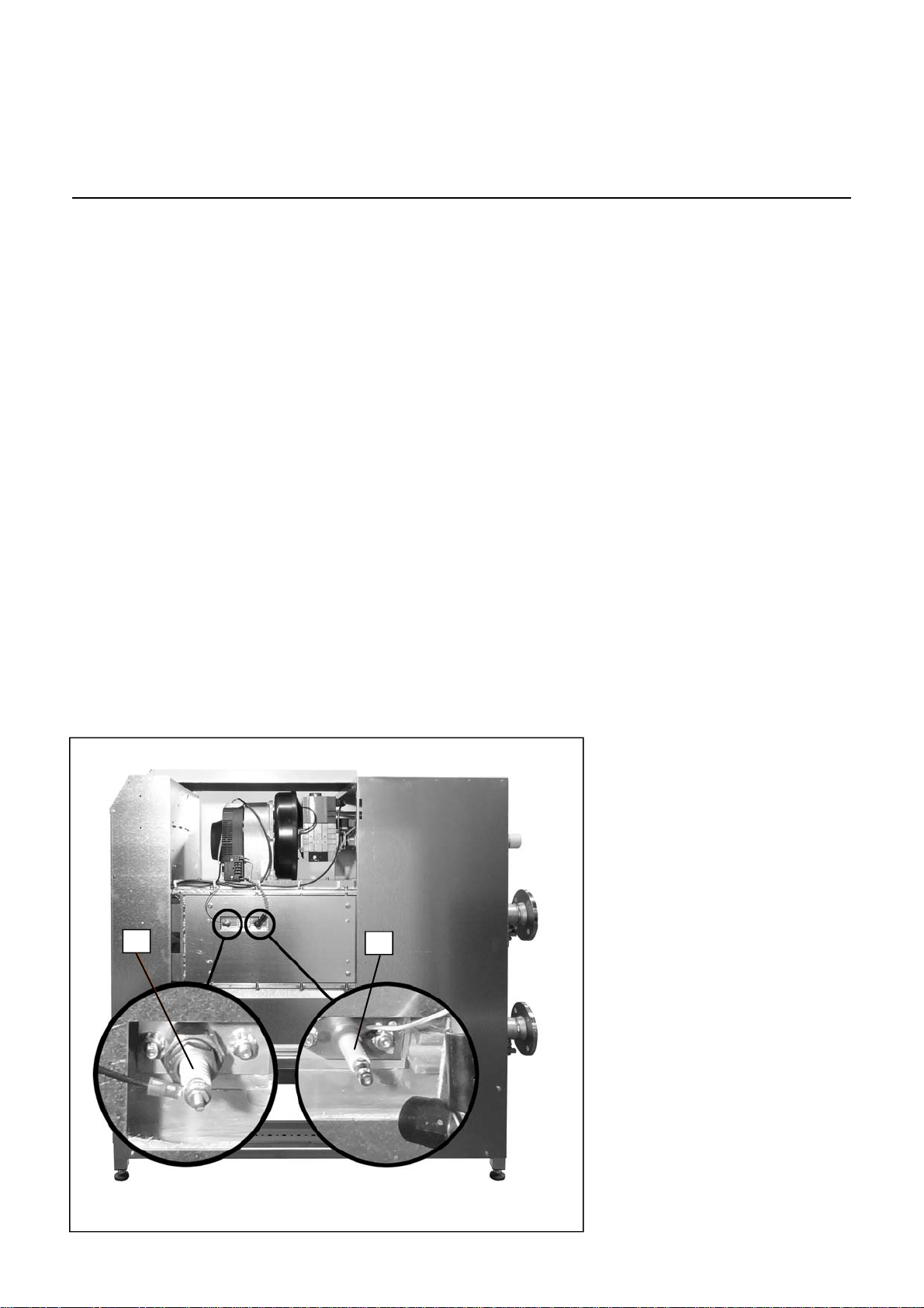
Replacing the electrodes
The electrodes are positioned on the
right hand side of the boiler. Replace
the ignition elektrode (1) and ionisation
eclectrode (2) as shown on the picture.
2
1
28
Page 29
Maintenance
Cleaning the condensate receptacle
Cleaning and refilling the syphon
Inspection of combustion chamber
2
1
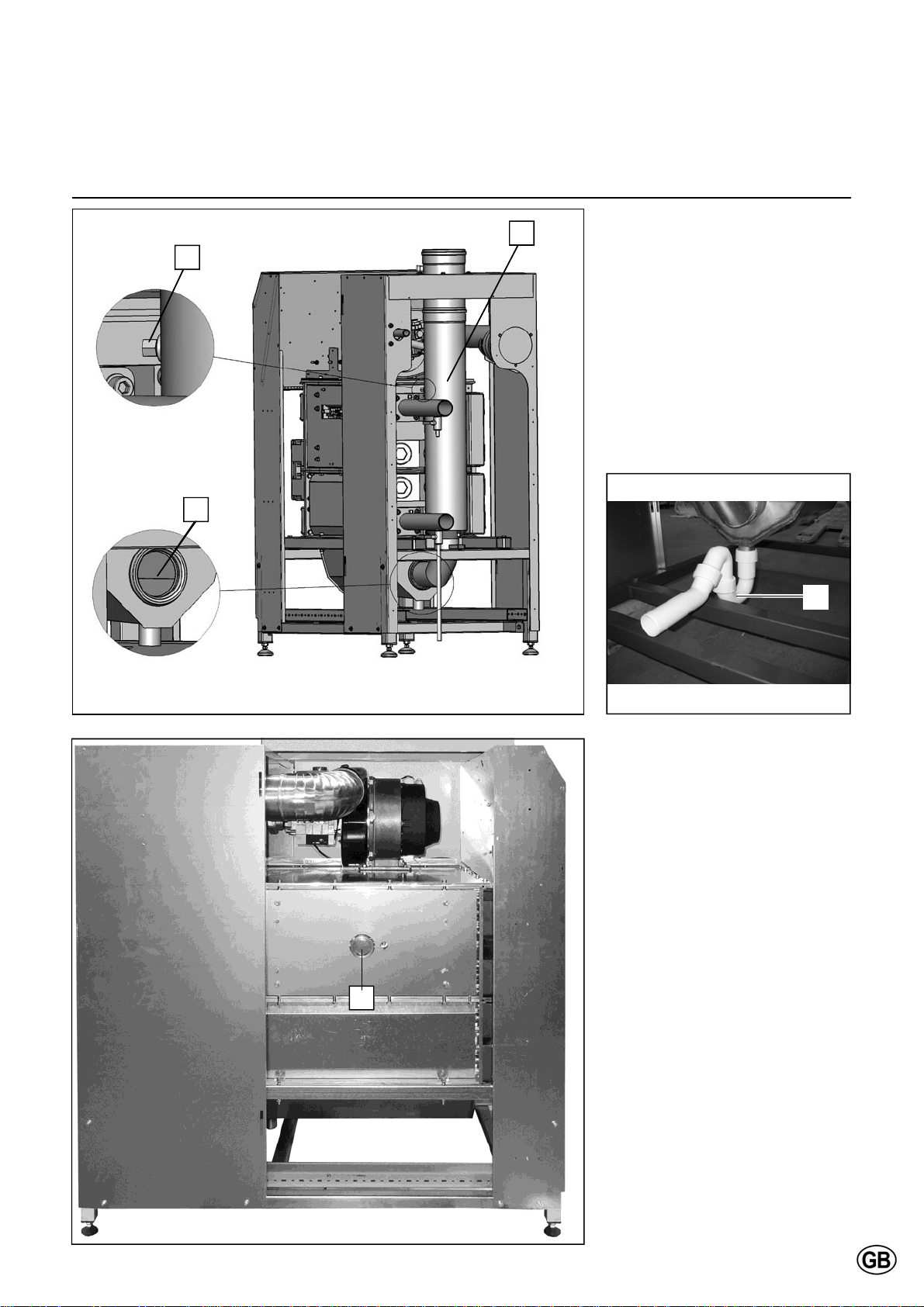
Cleaning the condensate receptacle
Disconnect the plug of the fluegas
temperature sensor (1);
Remove the internal fluegas pipe (2)
of the boiler in order to create access
to the condensate receptacle;
Clean the receptacle (3);
Mount the fluegas pipe back in posi-
tion when the cleaning is finished;
Connect the plug of the fluegas tem-
perature sensor.
3
4
Cleaning and refilling the syphon
Remove the syphon (4) from the con-
densate connection;
Clean and fill it with fresh water;
Mount the syphon back in the original
position.
Inspection of combustion chamber
The sight glass (5) is positioned on the
left hand side of the boiler.
Inspect the combustion chamber by
viewing through the sight glass.
5
Cleaning can be done with water:
Remove the viewing mirror and glass
from the sight glass holder;
Stick a garden hose through the sight
glass holder and rinse the heat
exchanger with water;
Reassemble the sight glass.
29
Page 30

Maintenance
Water pressure and quality
Check if the water pressure and quality
meet the requirements. Consult the
chapter “commissioning: water and
hydraulic system” for more detailed
information.
Water flow rate
Check if the water flow rate through the
boiler is within the limits. Consult the
chapter “commissioning: check water
flow” for more detailed information.
Combustion analysis
Check the combustion at full load and
minumum load, correct the settings if
necessary. An additional reference
check at 50% load is recommended.
Consult the chapter “commissioning:
combustion analysis” for more detailed
information.
Gas pressure
Check the dynamic pressure of the gas
supply to the boiler, when the boiler is
running at full load. In case of a boiler
cascade, all boilers should be running
at full load. See technical data for required values.
Gas tightness check
Check the tightness of all sealed connections with an approved soap or
electronic analyzer, for example:
Test points;
Bolt connections;
Gaskets of mixing system, etc.
Safety devices
Check the functionality and the settings
of all safety devices connected. Consult
the chapter “commissioning: Check
functionality of safety devices” for more
detailed information.
30
Page 31
Maintenance
Maintenance Protocol
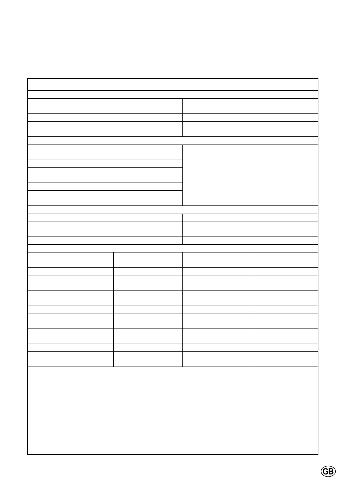
Maintenance Protocol R600
Project
Boiler type Project
Serial number Address
Year City
Nominal load (Hi) [kW] Date
Nominal output (Hi) [kW] Engi neer
System
Water pressure [bar]
Water pH [-]
Water hardness [dºH]
Water chloride [mg/l]
Water T full load [ºC]
Water p
Water flow [m
Pump setting [-]
Safety devices
High limit setting [ºC] Water flow sensor checked
Temp. limiter setting [ºC] Fluegas sensor checked
Min. gas pressure switch setting [mbar]
Ignition time burner [sec]
Combustion analysis
Gas consumption [m
Gas pressure [mbar] [mbar] [mbar]
[%] [%] [%]
CO
2
O2 [%] [%] [%]
CO [ppm] [ppm] [ppm]
NOx [ppm] [ppm] [ppm]
T
atmospheric
T
fluegas
T
water, flow
T
water, return
Ionisation current [µA] [µA] [µA]
[mbar] [mbar] [mbar]
p
fan
p
top panel
p
combustion chamber
Remarks
[kPa]
boiler
100% load 50% load Min. load
[ºC] [ºC] [ºC]
[ºC] [ºC] [ºC]
[ºC] [ºC] [ºC]
[ºC] [ºC] [ºC]
[mbar] [mbar] [mbar]
[mbar] [mbar] [mbar]
3
/h]
3
/h] [m3/h] [m3/h]
31
Page 32

Lockouts
In case of a lockout, a warning symbol ( ) and a flashing error code appears on the display. The cause of a fault should first
be determined and eliminated before the boiler is being reset. T he table below shows all possible lockouts with indication of
possible cause.
Error
Description of error
code
0 No error
10 Outside temperature sensor error
20 Boiler temperature 1 sensor error
26 Common flow temperature sensor error
28 Flue gas temperature sensor error
30 Flow temperature 1 sensor error
32 Flow temperature 2 sensor error
38 Flow temperature primary controller sensor error
40 Return temperature 1 sensor error
46 Return temperature cascade sensor error
47 Common return temperature sensor error
50 DHW temperature 1 sensor error
52 DHW temperature 2 sensor error
54 DHW primary controller sensor error
57 DHW circulation temperature sensor error
60 Room temperature 1 sensor error
65 Room temperature 2 sensor error
70 Buffer storage tank temperature 1 sensor error
71 Buffer storage tank temperature 2 sensor error
72 Buffer storage tank temperature 3 sensor error
73 Collector temperature 1 sensor error
74 Collector temperature 2 sensor error
82 LPB address collision
83 BSB wire short-circuit
84 BSB address collision
85 BSB RF communication error
91 EEPROM error lockout information
98 Extension module 1 error (collective error)
99 Extension module 2 error (collective error)
100 2 clocktime masters (LPB)
102 Clocktime master without reserve (LPB)
103 Communication error
105 Maintenance message
109 Boiler temperature supervision
110 STB lockout
111 TW cutout
121 Flow temperature 1 (HC1) supervision
Flow temperature 2 (HC2) supervision
122
125 Pump supervision error
126 DHW charging supervision
127 Legionella temperature not reached
128 Loss of flame during operation
129 Fan error or LP error
Flue gas temperature limit exceeded
130
Burner fault
131
132 GP or LP error
133 No flame during safety time
146 Configuration error collective message
32
Page 33

Lockouts
Error
Description of error
code
151 Internal error
152 Parameterization error
153 Unit manually locked
160 Fan error
162 LP error, does not close
164 Error heating circuit flow switch
166 LP error, does not open
171 Alarm contact H1 or H4 active
172 Alarm contact H2 (EM1, EM2 or EM3) or H5 active
173 Alarm contact H6 active
174 Alarm contact H3 or H7 active
178 Limit thermostat heating circuit 1
179 Limit thermostat heating circuit 2
183 Unit in parameterization mode
193 Pump supervision error after flame on
216 Fault boiler
217 Fault sensor
241 Flow sensor solar sensor error
242 Return sensor solar sensor error
243 Swimming pool temperature sensor error
270 Limit function
317 Mains frequency outside permissible range
320 DHW charging temperature sensor error
324 BX same sensors
325 BX / extension module same sensors
326 BX / mixing group same sensors
327 Extension module same function
328 Mixing group same finction
329 Extension module / mixing group same function
330 Sensor BX1 no function
331 Sensor BX2 no function
332 Sensor BX3 no function
333 Sensor BX4 no function
334 Sensor BX5 no function
335 Sensor BX21 no function (EM1, EM2 or EM3)
336 Sensor BX22 no function (EM1, EM2 or EM3)
337 Sensor BX1 no function
338 Sensor BX12 no function
339 Collector pump Q5 not available
340 Collector pump Q16 not available
341 Solar Collector sensor B6 not available
342 DHW sensor B31 not available
343 Solar integration not available
344 Solar controlling element buffer K8 not available
345 Solar controlling element swimming pool K18 not available
346 Solid fuel boiler pump Q10 not available
347 Solid fuel boiler comparison sensor not available
348 Solid fuel boiler address error
33
Page 34

Lockouts
Error
Description of error
code
349 Buffer return valve Y15 not available
350 Puffer address sensor
351 Primary controller / system pump address error
352 Pressureless header address error
353 Common flow sensor B10 not available
371 Flow temperature 3 (heating circuit 3) supervision
372 Limit thermostat heating circuit 3
373 Extension module 3 error (collective error)
349 Buffer return valve Y15 not available
350 Puffer address sensor
351 Primary controller / system pump address error
352 Pressureless header address error
353 Common flow sensor B10 not available
371 Flow temperature 3 (heating circuit 3) supervision
372 Limit thermostat heating circuit 3
373 Extension module 3 error (collective error)
386 Fan speed has lost valid range
388 DHW error no function
426 Feedback flue gas damper
427 Configuration flue gas damper
431 Sensor primary heat exchanger
432 Functional earth not connected
433 Temperature primary heat exchanger to high
34
Page 35
Sensor values
60000
55000
50000
45000
40000
35000
30000
25000
Resistance [Ohm]
20000
15000
10000
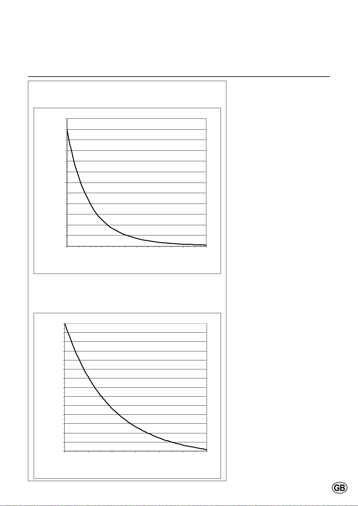
NTC 10kΩ temperature sensor
(flow, return, flue gas, DHW and header sensor)
5000
0
-10 0 10 20 30 40 50 60 70 80 90 100 110
Temperature [ºC]
The diagrams show the sensor values
for all boiler sensors and optional sensors available in accessory kits.
The diagrams contain average values,
as all sensors are liable to tolerances.
When measuring the resistance values,
the boiler should always be switched
off. Measure close to the sensor, in
order to avoid value deviations.
NTC 1kΩ temperature sensor
(outdoor sensor)
7500
7000
6500
6000
5500
5000
4500
4000
3500
3000
Resistance [Ohm]
2500
2000
1500
1000
500
-20-100 10203040
Temperature [ºC]
35
Page 36

Declaration of Conformity
Declaration of Conformity
Rendamax BV, Hamstraat 76, 6465 AG Kerkrade (NL),
Declares that the product
Is in conformity with the following standards:
And in accordance with the guidelines of directives:
92 / 42 / EEC (boiler efficiency directive)
2009 / 142 / EEC (gas appliance directive)
2006 / 95 / EEC (low voltage directive)
2004 / 108 / EEC (EMC directive)
This product is designated with CE number:
R600
EN 298
EN 656
EN 15420
EN 55014-1 / -2
EN 61000-3-2 /-3
EN 60 335-1/ -2
36
CE – 0063BS3840
Kerkrade, 17-04-2013
A.J.G. Schuiling
Plant Manager
Page 37

Page 38

STOKVIS ENERGY SYSTEMS
96R Walton Road
East Molesey
Surrey
KT8 0DL
Tel: 020 8783 3050 / 0870 7707747
Fax: 020 8783 3051 / 0870 7707767
E-Mail: [email protected]
Website: www.stokvisboilers.com
420010567300 12/2013
 Loading...