

Stoelting O111I Service Manual

Model O111I
SERVICE MANUAL
Manual No. 513662 Sept. 2010


This manual provides basic information about the machine. Instructions and suggestions are
given covering its operation and care.
The illustrations and specifi cations are not binding in detail. We reserve the right to make
changes to the machine without notice, and without incurring any obligation to modify or provide new parts for machines built prior to date of change.
DO NOT ATTEMPT to operate the machine until instructions and safety precautions in this
manual are read completely and are thoroughly understood. If problems develop or questions
arise in connection with installation, operation, or servicing of the machine, contact Stoelting.
stoeltingfoodservice.com
Stoelting Foodservice Equipment
502 Highway 67
Kiel, WI 53042-1600
U.S.A.
Main Tel: 800.558.5807
Fax: 920.894.7029
Customer Service: 888.429.5920
Fax: 800.545.0662
Email: foodservice@stoelting.com
© 2014 PW Stoelting, LLC

A Few Words About Safety
Safety Information
Read and understand the entire manual before
operating or maintaining Stoelting equipment.
This manual provides the operator with information
for the safe operation and maintenance of Stoelting
equipment. As with any machine, there are hazards
associated with their operation. For this reason safety
is emphasized throughout the manual. To highlight
specifi c safety information, the following safety defi ni-
tions are provided to assist the reader.
The purpose of safety symbols is to attract your attention to possible dangers. The safety symbols, and
their explanations, deserve your careful attention
and understanding. The safety warnings do not by
themselves eliminate any danger. The instructions
or warnings they give are not substitutes for proper
accident prevention measures.
If you need to replace a part, use genuine Stoelting
parts with the correct part number or an equivalent
part. We strongly recommend that you do not use
replacement parts of inferior quality.
Safety Alert Symbol:
This symbol Indicates danger, warning or caution.
Attention is required in order to avoid serious personal injury. The message that follows the symbol
contains important information about safety.
Signal Word:
Signal words are distinctive words used throughout
this manual that alert the reader to the existence and
relative degree of a hazard.
WARNING
The signal word “WARNING” indicates a potentially
hazardous situation, which, if not avoided, may result
in death or serious injury and equipment/property
damage.
CAUTION
The signal word “CAUTION” indicates a potentially
hazardous situation, which, if not avoided, may result
in minor or moderate injury and equipment/property
damage.
CAUTION
The signal word “CAUTION” not preceded by the
safety alert symbol indicates a potentially hazardous
situation, which, if not avoided, may result in equipment/property damage.
NOTE (or NOTICE)
The signal word “NOTICE” indicates information or
procedures that relate directly or indirectly to the
safety of personnel or equipment/property.

TABLE OF
CONTENTS
Section Description Page
1 Description and Specifications
1.1 Description .................................................................................................1
1.2 Specifications.............................................................................................2
1.3 Modes of Normal Operation ........................................................................3
1.4 Mix Level Indicators....................................................................................5
1.5 Hopper Refrigeration ...................................................................................5
1.7 Motor Profile Cutout Compensation ............................................................5
2 Installation Instructions
2.1 Safety Precautions.....................................................................................7
2.2 Shipment and Transit .................................................................................8
2.3 Machine Installation....................................................................................8
3 Initial Set-Up and Operation
3.1 Operator’s Safety Precautions....................................................................9
3.2 Operating Controls and Indicators...............................................................9
3.3 Important Information Regarding Cleaning and Sanitizing............................11
3.4 Disassembly of Parts .................................................................................12
3.5 Cleaning Disassembled Parts.....................................................................13
3.6 Sanitizing Parts..........................................................................................13
3.7 Cleaning the Machine.................................................................................13
3.8 Assembling the Machine ............................................................................14
3.9 Sanitizing ...................................................................................................15
3.10 Initial Freeze Down and Operation ..............................................................15
3.11 Normal Freeze Down and Operation ...........................................................16
3.12 Mix Information...........................................................................................17
4 Maintenance and Adjustments
4.1 Machine Adjustment...................................................................................19
4.2 Product Consistency Adjustment ...............................................................19
4.3 Locking the Control Panel...........................................................................19
4.4 Obtaining Readings and Modifying Settings................................................19
4.5 Readings ....................................................................................................21
4.6 Adjustments...............................................................................................22
4.7 Other Settings............................................................................................22
4.8 Drive Belt Tension Adjustment....................................................................23
4.9 Condenser Cleaning ...................................................................................24
4.10 Preventative Maintenance ...........................................................................24
4.11 Extended Storage.......................................................................................24

Section Description Page
5 Refrigeration System
5.1 Refrigeration System ..................................................................................25
5.2 Refrigerant Recovery and Evacuation ..........................................................25
5.3 Refrigerant Charging ...................................................................................26
5.4 Compressor................................................................................................27
5.5 Condenser ..................................................................................................28
5.6 Evaporator ..................................................................................................28
5.7 Valves ........................................................................................................28
A. Thermostatic Expansion Valve (TXV)..................................................................28
B. Check Valve.........................................................................................................29
C. High Pressure Cutout ......................................................................................... 29
D. Hot Gas Bypass.................................................................................................. 30
E. Evaporator Pressure Regulator (EPR) ............................................................... 3 1
F. Water Valve (Water Cooled Models Only) ...........................................................31
5.8 Solenoid .....................................................................................................32
5.9 Filter Drier ..................................................................................................33
5.10 Capillary Tube ............................................................................................33
6 Electrical and Mechanical Control Systems
6.1 IntelliTec Controller .....................................................................................35
6.2 Contactors..................................................................................................35
6.3 Drive Motor .................................................................................................36
6.4 Capacitors ..................................................................................................37
6.5 Gearbox .....................................................................................................37
6.6 Condenser Fan Motor (Air Cooled Models Only) .........................................38
6.7 Spigot Switch.............................................................................................38
6.8 Temperature Control Sensor .......................................................................39
7 Troubleshooting
7.1 Error Codes ................................................................................................41
7.2 Troubleshooting ..........................................................................................41
7.3 Troubleshooting - Machine..........................................................................44
8 Replacement Parts
8.1 Auger & Front Door Parts...........................................................................45
8.2 Hopper Cover & Trays.................................................................................46
8.3 Spigot Cam Assembly................................................................................46
8.4 Left Side & Air Cooled Condenser ..............................................................47
8.5 Right Side ..................................................................................................48
8.6 Machine Front ............................................................................................49
8.7 Electrical Panel ..........................................................................................50
8.8 Parts Kits................................................................................................... 50
8.9 Decals & Miscellaneous.............................................................................51
8.10 Panels........................................................................................................51
8.11 Wiring Diagram...........................................................................................52
SECTION 1
DESCRIPTION AND SPECIFICATIONS
1.1 DESCRIPTION
The Stoelting Optima 111 counter machine is gravity fed.
The machine is equipped with fully automatic controls to
provide a uniform product. The machine is designed to
operate with almost any type of commercial soft serve or
non-dairy mix available, including ice milk, ice cream,
yogurt, and frozen dietary desserts. This manual is designed to assist qualified service personnel and operators
in the installation, operation and maintenance of the Stoelting
O111 gravity machine.
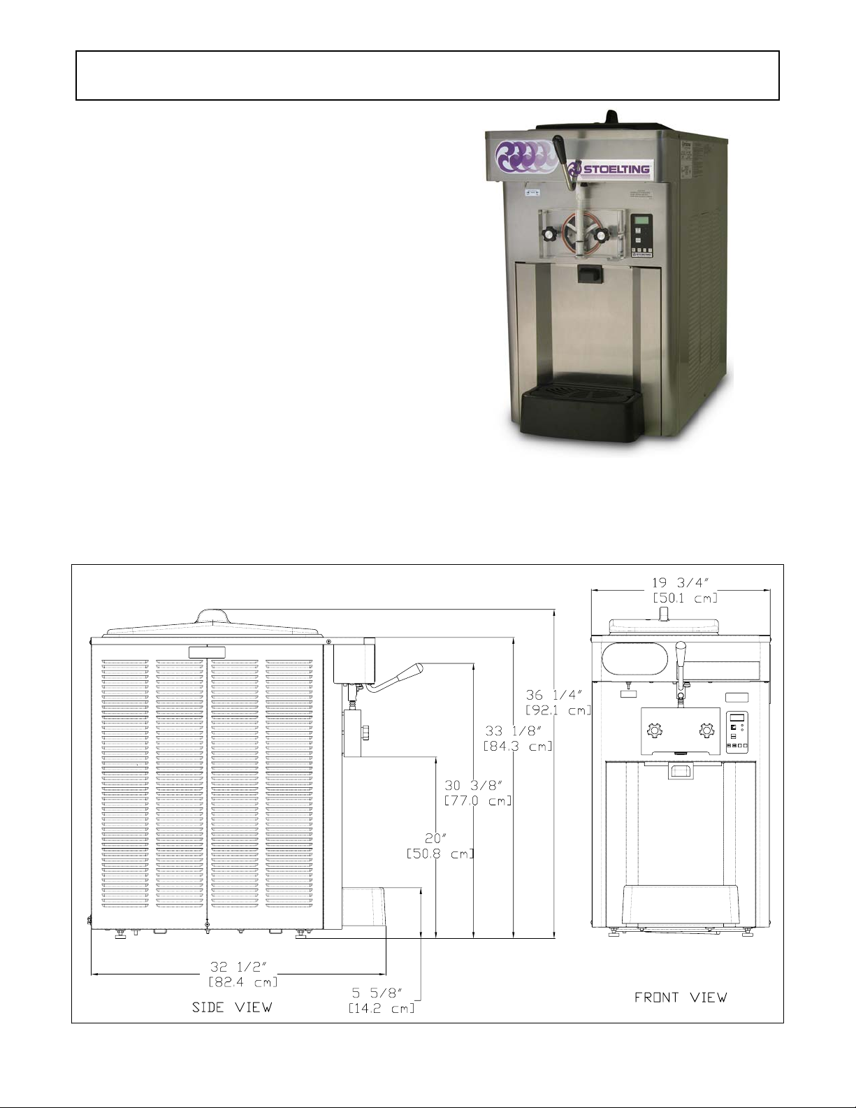
Figure 1-1 Model O111
Figure 1-2 Specifications
1
1.2 SPECIFICATIONS
Dimensions
width
height
depth
Weight
Electrical
run nin g amp s
connection type
International Option
Compressor
Drive Motor
Air Fl ow
Plumbi ng Fi t t i ngs
Maximum water pressure of 130 psi. Min imum water flow rate of 3 GPM. Ideal
Model O111I
Machine
19-3/ 4 '' (50,2 c m )
36-1/ 4 '' (92,1 c m )
32-1/ 2 '' (82,6 c m )
1 Phase, 208- 240 VAC, 60Hz
approx imatel y 12A
NEMA6-20P power cor d pr ovided
1 Pha se, 220 - 240 VAC, 50Hz
12,000 Btu/hr
1-1/2 hp
Air cool ed un it s r equire 3" ( 7, 6 cm ) air spac e on both sides
Water cool ed un its r equire 1/2" N. P.T. w at er and drain f ittings.
EWT o f 50°-70° F
with c rate
28-3/4'' ( 73,0 cm)
43'' ( 109, 2 c m )
38-3/4'' ( 98,4 cm)
400 lbs ( 181, 4 kg )310 lbs (140,6 kg)
Hopper Volume
Freezing Cylinder
Volume
Production
Capacity
Menu Display Value
Basic
Advanced
Storage
Cu tOut * amp s
Cut In T 21 °F
Cycles 20 cou nt
Stir On 15 secon ds
Stir Of f 300 secon ds
On Time 15 seconds
Of f Time 450 secon ds
Stb T ime 120 min u tes
Sl1DrvOn 120 secon ds
Sl1DrO ff 180 seconds
Sl2Cu t In 35 °F
Sl2CtO ut 30.5 ° F
DftO ffT m 600 seconds
Ref r iger 1 Hopper
Hpr Cu t In 34 °F
Hpr CtO ut 32 °F
HprOffst 8 °F
Hpr O ff 13 min utes
Hpr O n 60 secon ds
6.5 gall ons (24,61 liter s)
1 gall on (4 qu ar t ) , 3, 79 l iter s
11.5 GPH ( 4 3,53 lit er s )
Refrigerant
Charge
Suction Pressure
(at 72°F)
Discharge Pressure
Hot Gas Bypass
Pressure
EPR Valve
O111I
R-404A
(W/ C) 24 oz
(A/C) 32 oz
Freez in g Cy l in der O nly 20-22 psig
Freez ing Cyl in der & H opper 22-24 psig
Hopper O nly 18 psig
225-235 psig
18 psig (only h opper r un n ing)
59-61 psig
* CutOut value needs to be adjusted to product
requirements.
2

1.3 MODES OF NORMAL OPERATION
Following are details of the operational modes of the
IntelliTec control.
NOTE:
The preset amounts, times, and temperatures listed
below are references to actual settings on the
IntelliTec control. Refer to Table 1-1 on page 7 for
details on each setting.
A. Initial status
When the Main Freezer Power is placed in the ON position,
the machine will start in the “Sleep 1 Mode". The display will
read "Sleep 1 Mode". The control will eventually move into
the “Sleep 2” mode if the PUSH TO FREEZE button is not
pressed. When the PUSH TO FREEZE button is pressed
the control will move to the “Serve Mode”.
B. Serve Mode
When the PUSH TO FREEZE button is pressed or a spigot
handle is pulled, the “Serve Mode” begins. The drive motor
starts, and after a 3 second delay, the compressor starts.
The display reads “FREEZING” on the top line and a bar on
the bottom line increases with product consistency. A
toroid on the IntelliTec control senses increasing drive
motor amperage as the product comes to consistency in
the freezing cylinder. When the control senses the product
is at 75% of consistency, the display will read "SERVE",
the amber LED will go out, and the green LED will flash. At
this time, product can be served from the machine. The
drive motor and compressor will continue to run until the
toroid reads a preset value (CutOut amps). When the toroid
reads the CutOut amps on the drive motor, the compressor
turns off and the green LED will remain lit. After a 3 second
delay, the drive motor turns off. The product in the freezing
cylinder is now at serving temperature and consistency and
the green LED will remain lit.
After product is at consistency, the IntelliTec control
continuously monitors refrigerant temperature through a
thermistor mounted on the side of the freezing cylinder.
When the temperature increases to a preset amount (Cut
In T), a 3-second drive motor pre-stir analyzes product
consistency. The pre-stir check is also performed each
time the spigot handle is opened. This check prevents overfreezing of product, especially during frequent, small volume draws. If the product requires a freezing cycle, the
control will start the cycle.
During the “Serve Mode”, a stir cycle starts. This cycle is
independent of the freezing cycle and is based on preset
times (Stir On and Stir Off). The stir cycle prevents product
separation. If a freezing cycle is initiated, the timer is reset.
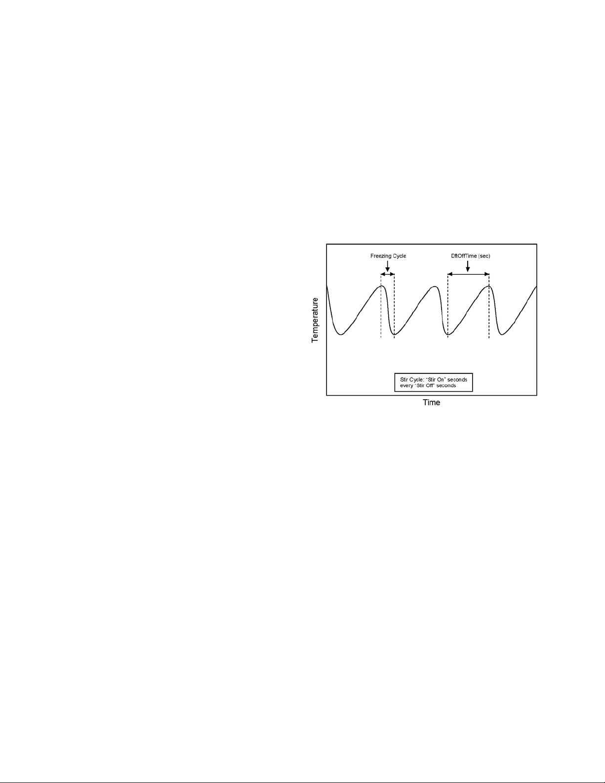
In addition to the "Serve Mode" freezing cycle, there is a
freezing cycle based on a preset time (DftOffTime). If this
time is attained without a freezing cycle, the control will
automatically start a freezing cycle. If a freezing cycle is
initiated, the timer is reset
Figure 1-3 Serve Mode
The machine will remain in “Serve Mode” until the cycle
count setting is attained. The cycle count is the number of
active freezing cycles and is based on a preset value
(Cycles). Once the cycle count has been reached without
user interruption, the control will move into the "Standby
Mode".
If the PUSH TO FREEZE button is pressed or a spigot
handle is pulled, the cycle count is reset and the control will
move to the beginning of the "Serve Mode". Refer to Figure
1-3 for a graphical representation of the "Serve Mode".
C. Standby Mode
If no product has been drawn from the spigot and the preset
number of active freezing cycles is met, the control moves
into the “Standby Mode”. In "Standby Mode", the freezing
cycle is based on preset timers (On Time and Off Time), and
prevents ice crystals from building up in the product.
Because the product remains partially frozen, it can quickly
return to servable consistency when the PUSH TO FREEZE
button is pressed.
During “Standby Mode”, the stir cycle runs. This cycle is
based on preset, timed intervals (Stir On and Stir Off) and
prevents product separation.
Figure 1-4 Standby Mode
3
The "Standby Mode" maintains product quality during slow
times, while minimizing reactivation time. This mode lasts
for a preset time (Stb Time). Once this time has been
reached without user interruption, the control moves into
the "Sleep 1 Mode". Refer to Figure 1-4 for a graphical
representation of the "Standby Mode".
If a spigot is opened or the PUSH TO FREEZE button is
pressed, the control will move to “Serve Mode”. Product in
the front of the freezing cylinders may or may not be at
consistency. The state of the product is dependant on a
number of variables but will come to consistency quickly.
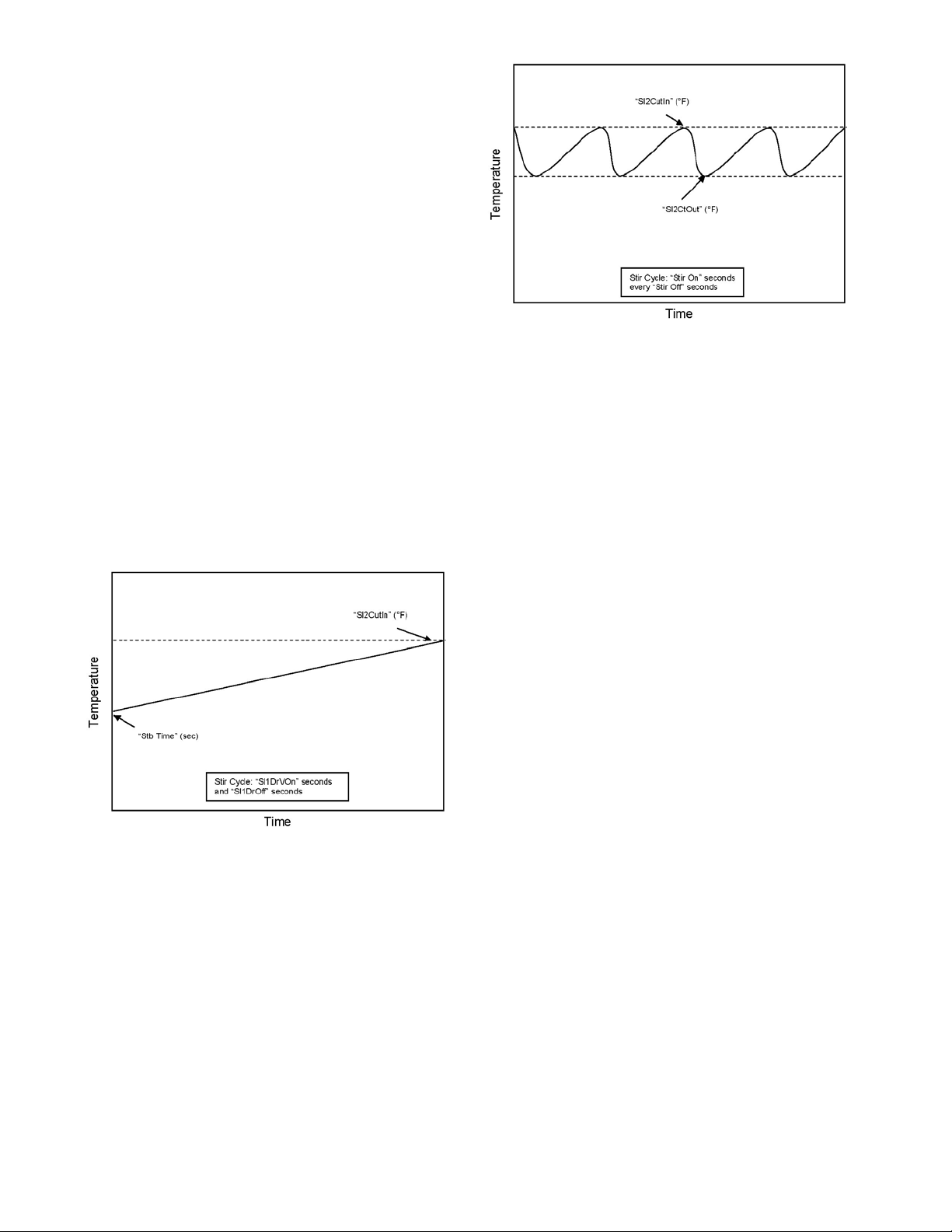
D. Sleep 1 Mode
After the “Standby Mode” time has expired without user
interruption, the control will move into the “Sleep 1 Mode”.
During the "Sleep 1 Mode", the stir cycle is handled by
preset timers (Sl1DrvOn and Sl1DrOff), and allows product
to melt to a liquid state by using agitation cycles without
any flow of refrigerant. Although the product temperature
never increases above 41°F, the product thaws rapidly
which minimizes product breakdown. The control will stay
in the “Sleep 1 Mode” until sensing a preset temperature
(Sl2CutIn). When this temperature has been reached
without user interruption, the control will move to the "Sleep
2 Mode". Refer to Figure 1-5 for a graphical representation
of the "Sleep 1 Mode".
Figure 1-5 Sleep 1 Mode
If a spigot is opened or the PUSH TO FREEZE button is
pressed, the control will move to “Serve Mode”. If the spigot
is opened in "Sleep 1 Mode", the product will not be at
consistency. The operator must wait until the first "Serve
Mode" freezing cycle has completed to serve product.
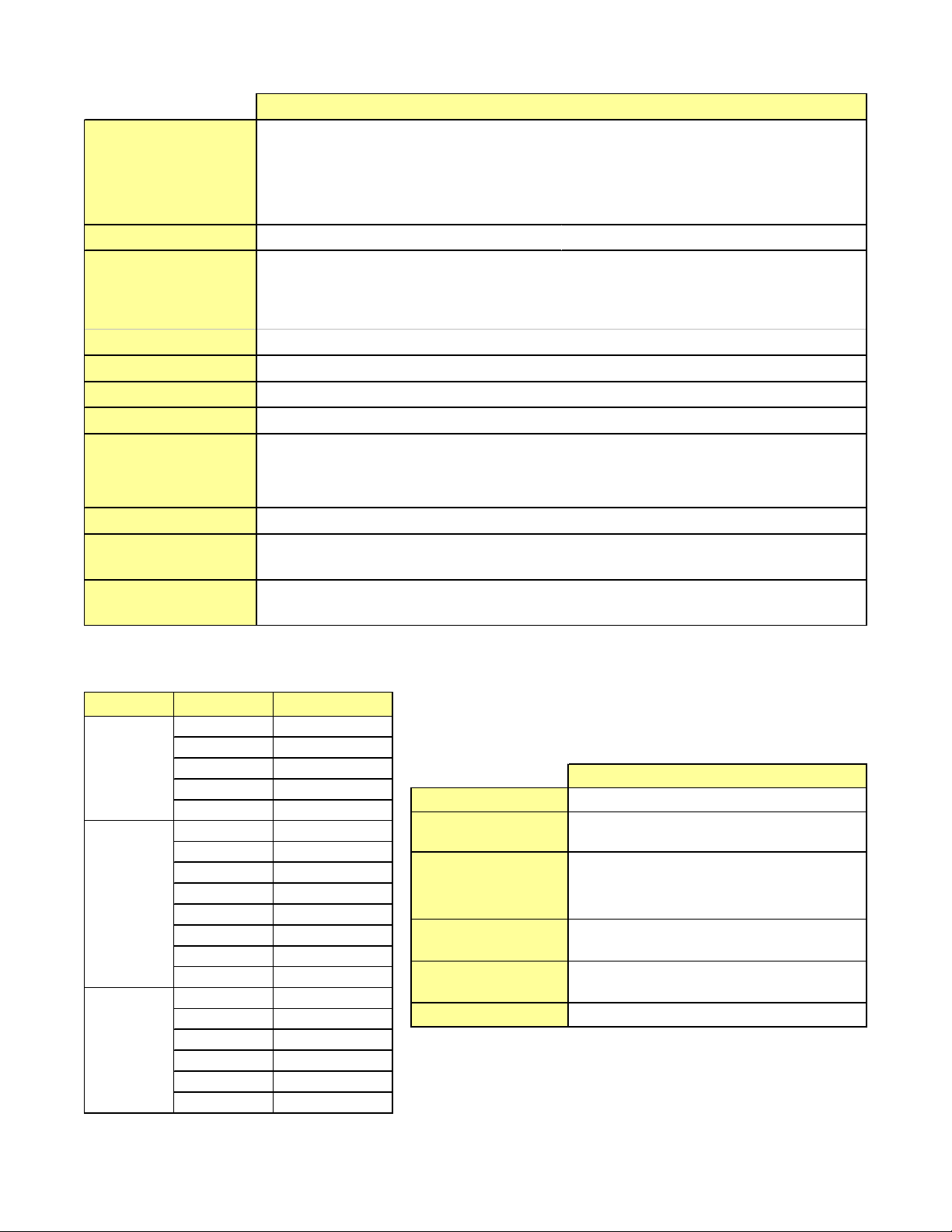
E. Sleep 2 Mode
The “Sleep 2 Mode” maintains the freezing cylinder temperature between two preset values (Sl2CutIn and Sl2CtOut).
During the “Sleep 2 Mode”, the stir cycle runs. This cycle
is based on preset, timed intervals (Stir On and Stir Off) and
prevents product separation. The "Sleep 2 Mode" is often
referred to by customers as the “night mode” and the
machine will stay in this mode until a spigot is opened or
the PUSH TO FREEZE button is pressed. When this
Figure 1-6 Sleep 2 Mode
occurs, the control will move to “Serve Mode”. If the spigot
is opened at this time, the product will be liquid. The
operator must wait until the first "Serve Mode" freezing
cycle has completed to serve product. Refer to Figure 1-6
for a graphical representation of the "Sleep 2 Mode".
F. IntelliTec Restart
If a hard error occurs (refer the hard error list below), the
IntelliTec control will wait 5 minutes then attempt to clear
the error by restarting itself. The control will count each
restart attempt. The restart count will reset if the PUSH TO
FREEZE button is pressed, the spigot is pulled, or the
Freezing Cylinder OFF/ON switch is placed in the OFF
position.
The following are considered hard errors:
ERROR CODE MALFUNCTION
2 High Torque
3 Run Time
4 Clean
7 Drive Motor
9 High Pressure Cutout
When a restart occurs, the second line of the display will
read "Restart" and the backlight will blink. This will occur
regardless of the system mode.
G. Sleep 3 Mode
If a high torque, run time, or drive motor error condition
occurs on the third restart attempt, the control will move to
the "Sleep 3 Mode".
In "Sleep 3 Mode" freezing cylinder refrigeration will run for
4 seconds every 10 minutes. This ensures the product
temperature never increases above 40°F. The stir cycle
and the auger do not run during "Sleep 3 Mode".
The control will exit "Sleep 3 Mode" if the PUSH TO
FREEZE button is pressed, the spigot is pulled, or the
Freezing Cylinder OFF/ON switch is placed in the OFF
position.
4
H. Clean Mode
When the CLEAN button is pressed, freezing cylinder
refrigeration stops, the drive motor starts and will run for
20 minutes, and a 5 minute countdown timer is displayed.
After the time has elapsed, an optional audible alarm will
sound if this accessory has been installed. The audible
alarm is a reminder for the operator to end the "Clean
Mode" when cleaning is completed.
If the machine is kept in "Clean Mode" for more than 20
minutes, the auger drive motor stops and an error code
(E4) is displayed on the display panel. The error code
prevents damage to the machine that could occur during
an extended clean mode (Refer to Section 8 - Troubleshooting for details). To clear this error, place the Freezing Cylinder Off/On switch in the OFF position and back
in the ON position. If the machine is still being cleaned,
pushing the CLEAN button will reset the timer and restart
the "Clean Mode".
1.4 MIX LEVEL INDICATORS
The hoppers are equipped with a sensor that monitors mix
level. When the mix level drops below the sensor probe,
the lower line of the display will read "Low Mix" and the
display will flash. To clear the "Low Mix" error, add mix to
the hopper.
A. Serve and Standby Mode
In the event of a temperature sensor failure on a freezing
cylinder, the IntelliTec control will function in two modes,
"Serve Mode" and "Standby Mode". When the product is at
consistency in "Serve Mode", the IntelliTec control uses a
timer instead of the sensor and will not start another
freezing cycle until a preset value (DftOffTme) is met.
The control will monitor product after it is at consistency,
activating the stir cycle and counting the number of cycles.
When the cycle count is reached, the control will move to
"Standby Mode".
The "Standby Mode" is the same as in normal operation
with the exception of when the preset time (Stb Time) is
met, the control moves back into the "Serve Mode". Refer
to Figure 1-7 for details.
1.5 HOPPER REFRIGERATION
The IntelliTec control is programmed to handle refrigeration of the hopper independently from the freezing cylinder. The control maintains hopper temperature between
two preset values (HprCutIn and HprCtOut).
The hopper refrigeration cycle starts when the temperature of either hopper reaches the HprCutIn value and stops
when hopper reaches the HprCutOut value.
In addition to this refrigeration cycle, hopper refrigeration
may start when the freezing cycle starts. This reduces
compressor cycles which preserves compressor life.
Hopper refrigeration will start if the hopper temperature is
above a preset value (HprOffst + HprCtOut). This value is
always between HprCutIn and HprCtOut. Refrigeration of
the hopper will continue until the HprCtOut is reached or
until the freezing cycle is completed in the freezing
cylinder.
The refrigeration cycle will run for a maximum of 4
minutes. After 4 minutes, the refrigeration cycle will stop
for a minimum of 3 minutes. At the expiration of 3 minutes,
the control will check product temperature. If product
temperature is at or above HprCutIn, another refrigeration
cycle will start.
1.6 OPERATION DURING SENSOR FAILURE
The IntelliTec control is designed to allow the machine to
continue to function if a temperature sensor failure occurs. If a sensor fails, the display will show the error and
the control will run the machine on timers for the freezing
cycle or hopper refrigeration. This allows the operator to
continue to serve product from the machine until proper
servicing can be completed.
Figure 1-7 Serve Mode (Sensor Failure)
In the event a hopper temperature sensor fails, the control
will use the temperature of the other hopper to control the
refrigeration cycle.
If both temperature sensors fail, the refrigeration cycle is
managed by preset times (Hpr On and Hpr Off). This
refrigeration cycle is independent of the freezing cycle.
1.7 MOTOR PROFILE CUTOUT
COMPENSATION
The IntelliTec control is programmed to automatically
function at a range of supply voltages. This feature provides
the advantage of having product maintained at a specific
temperature and consistency irrespective of the supply
voltage. A motor profile curve is programmed on the
IntelliTec control and provides a relationship between the
supply voltage and drive motor cutout amperage. Depending on the supply voltage, the control varies cutout amperage according to the motor profile. This feature is automatic
and does not need any configuring.
5

IntellITec Control Setting Specifications
Basic Menu
Advanced Menu
DISPLAY Value MODE DEFINITION
CutOut * Serve Amp draw setti ng for cut out
Cut In T 21°F Serve Temperature set ting for cut i n
Cycles 20 Serve Freezing cycles before going into Standby Mode
St ir On 15 sec S erve St ir-only on tim e
St i r Off 300 sec Serve Sti r-only off time
DISPLAY Value MODE DEFINITION
On Time 15 sec Standby Freezing cycle "on” time (runs on timers only)
Off Time 450 sec Standby Freezing cycle “off” time
St b Time 120 sec S tandby Total time i n m ode
Sl 1DrvOn 12 0 sec Sle ep 1 Drive moto r “on ” t i m er
Sl 1Dr Off 180 sec Sl eep 1 Drive mot or “o ff” ti m er
Sl2CutIn 35°F S l eep 2 Cut in temperature
Sl2Ct Out 30.5°F Sleep 2 Cut out t em perature
DftOffTm 600 sec No Sensor Default “off” time. Used in c ase of sens or failure
Storage M e nu
* The CutOut value needs to be adj usted t o produc t requirement s. Refer to t he 2183078 - S pecific at ion Sheet for O111
Control located i n t he plast i c pouch behi nd the header panel.
DISPLAY Value MODE DEFINITION
Refriger 1 Hopper All Set to None, 1 Hopper, 2 Hopper, or Cabi net
HprCutIn 34°F All Refrigerated c ab cut i n t emperature
HprCtOut 32°F Al l Refrigerated cab cut out tem perat ure
Hpr Off 13 min No S ensor Default “off” time. Used in c ase of sens or failure
Hpr On 60 sec No Sensor Default “on” time. Us ed i n case of s ensor failure
6

SECTION 2
INSTALLATION INSTRUCTIONS
2.1 SAFETY PRECAUTIONS
Do not attempt to operate the machine until the safety
precautions and operating instructions in this manual are
read completely and are thoroughly understood.
Take notice of all warning labels on the machine. The labels
have been put there to help maintain a safe working
environment. The labels have been designed to withstand
washing and cleaning. All labels must remain legible for the
life of the machine. Labels should be checked periodically
to be sure they can be recognized as warning labels.
If danger, warning or caution labels are needed, indicate
the part number, type of label, location of label, and quantity
required along with your address and mail to:
STOELTING, INC.
ATTENTION: Customer Service
502 Hwy. 67
Kiel, Wisconsin 53042
Figure 2-1 Warning Label Locations
7
2.2 SHIPMENT AND TRANSIT
The machine has been assembled, operated and inspected
at the factory. Upon arrival at the final destination, the
complete machine must be checked for any damage which
may have occurred during transit.
With the method of packaging used, the machine should
arrive in excellent condition. THE CARRIER IS RESPONSIBLE FOR ALL DAMAGE IN TRANSIT, WHETHER VISIBLE OR CONCEALED. Do not pay the freight bill until the
machine has been checked for damage. Have the carrier
note any visible damage on the freight bill. If concealed
damage and/or shortage is found later, advise the carrier
within 10 days and request inspection. The customer must
place claim for damages and/or shortages in shipment with
the carrier. Stoelting, Inc. cannot make any claims against
the carrier.
2.3 MACHINE INSTALLATION
Installation of the machine involves moving the machine
close to its permanent location, removing all crating,
setting in place, assembling parts, and cleaning.
A. Uncrate the machine.
B. Accurate leveling is necessary for correct drainage
of the freezing cylinder and to insure correct
overrun. Place a bubble level on top of the machine
at each corner to check for level condition. If
adjustment is necessary, level the machine by
turning the bottom part of each leg in or out. Then
separate machine base gasket and install with
seam to the back and angle to the top.
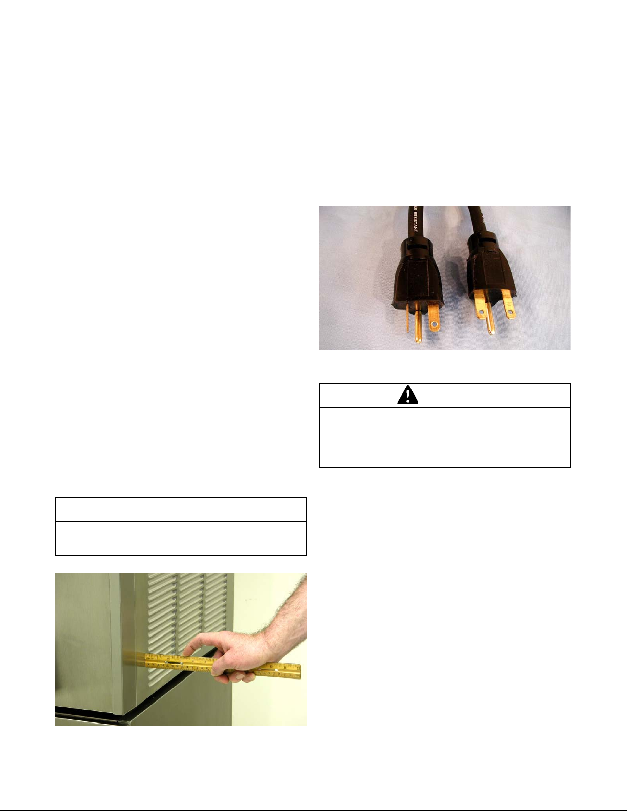
C. If the machine is equipped with an air cooled
condenser, correct ventilation is required. The right
side of the machine is the air intake and left side
discharge. Both sides must have 3" clearance the
top requires 10" of clearance.
CAUTION
D. Place the OFF-ON switch in the OFF position.
E. Connect the power cord to the proper power
supply. The plug is designed for 208 or 230 volt/20
amp duty. Check the nameplate on your machine
for proper supply. The unit must be connected to
a properly grounded receptacle. The electrical
cord furnished as part of the machine has a three
prong grounding type plug (Fig. 2-3). The use of an
extension cord is not recommended, if necessary
use one with a size 12 gauge or heavier with ground
wire. Do not use an adapter to get around grounding
requirement.
208/230V
115V
20 Amp
Figure 2-3 Electrical Plug
WARNING
Do not alter or deform electrical plug in any way.
Altering the plug to fit into an outlet of different configuration may cause fire, risk of electrical shock,
product damage and will void warranty .
F. Install the drip tray, drain tray, hopper cover and
other miscellaneous parts on the machine.
20 Amp
Failure to provide adequate ventilation will void warranty.
Figure 2-2 Space and Ventilation Requirements
8
SECTION 3
INITIAL SETUP AND OPERATION
3.1 OPERATOR’S SAFETY PRECAUTIONS
SAFE OPERATION IS NO ACCIDENT; observe these
rules:
A. Know the machine. Read and understand the
Operating Instructions.
B. Notice all warning labels on the machine.
C. Wear proper clothing. Avoid loose fitting garments,
and remove watches, rings or jewelry that could
cause a serious accident.
D. Maintain a clean work area. Avoid accidents by
cleaning up the area and keeping it clean.
E. Stay alert at all times. Know which switch, push
button or control you are about to use and what
effect it is going to have.
F. Disconnect electrical cord for maintenance. Never
attempt to repair or perform maintenance on the
machine until the main electrical power has been
disconnected.
G. Do not operate under unsafe operating conditions.
Never operate the machine if unusual or excessive
noise or vibration occurs.
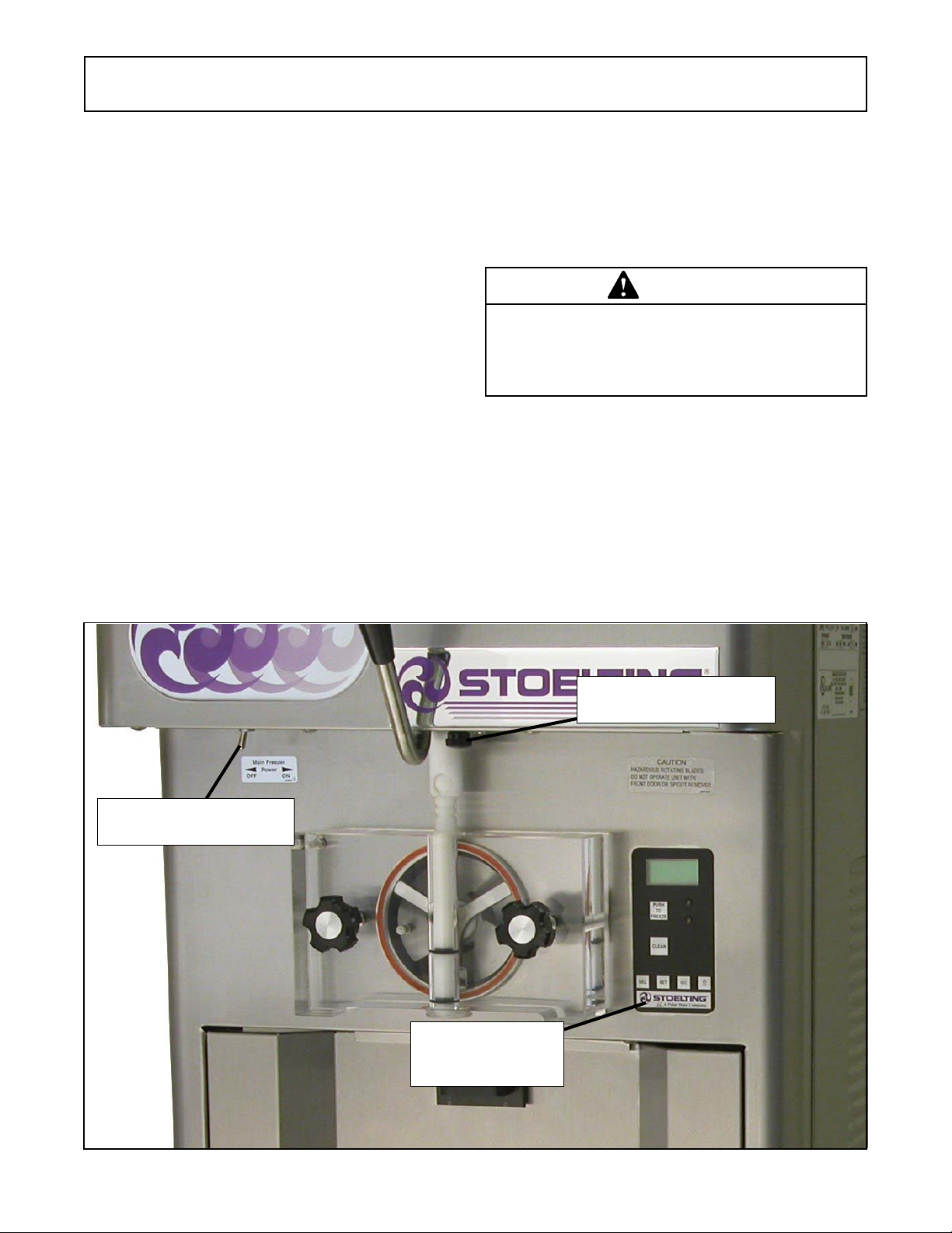
3.2 OPERATING CONTROLS AND
INDICATORS
Before operating the machine, it is required that the
operator know the function of each operating control. Refer
to Figure 3-1 for the location of the operating controls on the
machine.
WARNING
High voltage will shock, burn or cause death. The
OFF-ON switch must be placed in the OFF position
prior to disassembling for cleaning or servicing. Do
not operate machine with cabinet panels removed.
A. Spigot Switch
The spigot switch will automatically actuate the
auger drive and refrigeration systems when the
spigot is opened to dispense product. When the
spigot is closed, the drive motor and compressor
will remain “on” until the product in the barrel
reaches the proper consistency.
Main Power OFF-ON
Dispense Rate Adjustor
IntelliT ec Control
(See Figure 3-2)
Figure 3-1 O11 1 Controls
9

B. Main Freezer Power OFF-ON Switch
The Main Freezer Power OFF-ON switch is a two
position toggle switch used to supply power to the
control circuit. When the switch is in the OFF
position, power will not be supplied to the control
board or refrigeration system. When the switch is
in the ON position, the machine will operate in the
freezing mode or cleaning mode. The machine will
be in the sleep mode until a switch is activated.
C. PUSH TO FREEZE Button
The PUSH TO FREEZE button is used to initiate
the serve mode. To start the machine, place the
Main Freezer Power OFF-ON switch in the ON
position and press the PUSH TO FREEZE button.
NOTE
After the drive motor starts, there is a 3 second delay before the compressor starts.
D. LEDs
The membrane switch features two lights; a green
LED and an amber LED. The green LED is lit during
serve mode. During freeze down, the green LED is
not lit. When product consistency approaches
75% in the freezing cylinder, the green LED flashes.
The amber LED is lit during all other modes. In the
event of an error or when the freezing cylinder is off,
both LEDs will alternatively flash.
NOTE
If the machine shuts off, and alternating green and
amber lights are flashing, the machine is in an error
condition. If the LCD displays an error, turn the Main
Freezer Power OFF-ON switch to the OFF position,
correct the problem (Refer to Troubleshooting in
Section 4) and turn the machine back on.
E. CLEAN Button
The CLEAN button will stop all refrigeration and
start auger rotation. A CLEAN message will display
on the LCD screen and a 5 minute timer begins. To
exit the CLEAN mode, press the CLEAN button
again. If the machine is left in CLEAN for more than
20 minutes, it will go into an error to prevent
damage to the freezing cylinder. When this error
occurs, refrigeration will start to prevent mix
spoilage. To reset, place the Main Freezer Power
OFF-ON switch in the OFF position and back in the
ON position.
F. Mix Low Light Indicator
The MIX LOW message will appear on the LCD
display to alert the operator to a low mix condition.
The message will display when there is
approximately one gallon of mix left in the hopper.
When the MIX LOW message is displayed, refill
hopper immediately.
NOTE
Failure to refill hopper immediately may result in
operational problems.
G. Dispense Rate Adjustor
The dispense rate adjuster limits the opening of the
spigot. To adjust product dispense rate, turn the
adjusting knob clockwise for slower flow and
counterclockwise for faster flow. It takes at least
five complete turns of the adjusting knob to make
a noticeable difference in the dispense rate.
H. Front Door Safety Switch
The front door safety switch prevents the auger
from turning when the front door is removed. The
switch is open when the door is not in place and
closed when the door is properly installed.
I. Manu Navigation Buttons
The Menu Navigation Buttons allow the user to
display information regarding the machine's status
of operation as well as adjust product consistency.
Selection Button (SEL) The SEL button is not
functional in the normal operation mode. This
button is only used by service technicians for
machine calibration.
Set Button (SET) Pressing this button will save a
change made to the product consistency setting.
Refer to Section 3-15 for consistency adjustment
procedures.
Left Arrow Button (⇐) Pressing any button on the
control panel will automatically illuminate the
display. The backlight will turn off several seconds
after use. To keep the display constantly lit, press
and hold the left (⇐) button for five seconds. The
backlight function can be reset to normal operation
in the same manner.
Up Arrow Button (⇑) Pressing this button will
change the value of the product consistency. Refer
to Section 3-15 for consistency adjustment
procedures.
Push to Freeze
Green Light
Amber Light
Clean Switch
SEL Button
SET Button
Left Arrow Button
Up Arrow Button
Figure 3-2 IntelliT ec Control
10

3.3 IMPORTANT INFORMATION REGARDING
CLEANING AND SANITIZING
Soft serve and shake machines require special consideration when it comes to food safety and proper cleaning and
sanitizing.
The following information specifically covers issues for
cleaning and sanitizing frozen dessert machines. This
information is meant to supplement a comprehensive food
safety program.
Soil Materials Associated with Frozen Dessert Machines
MILKFAT/BUTTERFAT – As components of ice-cream/
frozen custard mix, these soils will accumulate on the
interior surfaces of the machine and its parts. Fats are
difficult to remove and help attribute to milkstone buildup.
MILKSTONE – Is a white/gray film that forms on equipment
and utensils that are exposed to dairy products. These films
will accumulate slowly on surfaces because of ineffective
cleaning, use of hard water, or both. Milkstone is usually a
porous deposit, which will harbor microbial contaminants
and eventually defy sanitizing efforts.
Once milkstone has formed, it is very difficult to remove.
Without using the correct product and procedure, it is
nearly impossible to remove a thick layer of milkstone.
(NOTE: general-purpose cleaners DO NOT remove
milkstone.) This can lead to high bacteria counts and a food
safety dilemma.
IT IS BEST TO CONTROL MILKSTONE ON A DAILY
BASIS BEFORE IT CAN BECOME A SIGNIFICANT FOOD
SAFETY PROBLEM.
In addition to food safety, milkstone can cause premature
wear to machine parts, which can add to costs for replacement parts or possibly more expensive repairs if worn
machine parts are not replaced once they have become
excessively worn.
Important Differences Between Cleaning and
Sanitizing
CLEANING vs. SANITIZING
It is important to distinguish between cleaning and sanitiz-
ing. Although these terms may sound synonymous, they
are not. BOTH are required for adequate food safety and
proper machine maintenance.
CLEANING
• Is the removal of soil materials from a surface.
• Is a prerequisite for effective sanitizing.
NOTE
An UNCLEAN surface will harbor bacteria that can
defy sanitizing efforts.
Bacteria can develop and resist sanitizing efforts within a
layer of soil material (milkstone). Thorough cleaning procedures that involve milkstone removal are critical for operators of frozen dessert machines.
SANITIZING
• Kills bacteria.
• Can be effective on clean surfaces only.
NOTE
Using a SANITIZER on an unclean surface will not
guarantee a clean and safe frozen dessert machine.
Proper Daily Maintenance:
The Only Way to Assure Food Safety and Product Quality
Proper daily maintenance can involve a wide variety of
products and procedures. Overall, the products and procedures fall into three separate categories. (Please note that
this is a brief overview intended for informational purposes
only.)
1. CLEANING – This involves draining mix from the
freezing cylinder and rinsing the machine with
water. Next, a cleaner is run through the machine.
Then, the machine is disassembled and removable
parts are taken to the sink for cleaning.
2. MILKSTONE REMOVAL – Since most cleaners
do not have the ability to remove milkstone, the use
of a delimer becomes necessary. Although this
procedure may not be needed on a daily basis, it
will usually follow the cleaning procedure. It requires
letting a delimer solution soak in the machine for an
extended period. Individual parts are also soaked
in a deliming solution for an extended period of time
(more about delimers in Additional Information).
3. SANITIZING – After the machine has been cleaned
and contains no milkstone, the machine is
reassembled. Then a FDA-approved sanitizing
solution is run through the machine to kill bacteria.
The machine is then ready for food preparation.
As a recommended cleaner and sanitizer for your frozen
dessert machine, STERA-SHEEN has proven to be one of
the best daily maintenance products for:
• CLEANING – Thorough removal of all solids
including butterfat and milk fat.
• MILKSTONE REMOVAL – Complete removal of
milkstone.
• SANITIZING – FDA-approved no rinse sanitizer for
food contact surfaces.
Additional Information
THE USE OF DELIMERS
A delimer is a strong acid that has the ability to dissolve
milkstone. This type of chemical may become necessary
once high levels of milkstone have developed. While these
products are very effective for removing HIGH levels of
milkstone, they are not ideal for two reasons:
1. PRODUCT SAFETY – Strong acids are dangerous
chemicals. Carefully follow safety instructions
provided with delimer products.
11
2. MACHINE DAMAGE – Strong acids will attack
metal and rubber causing premature wear of parts.
The use of a delimer needs to be closely monitored
to avoid damage to machine surfaces and parts.
With proper daily use of STERA-SHEEN or its equivalent,
there is no need for the use of a DELIMER.
DO NOT USE BLEACH
• BLEACH HAS ABSOLUTELY NO CLEANING
PROPERTIES.
• BLEACH IS CORROSIVE. It will damage
components of the machine causing premature
wear and metal corrosion.
GENERAL PURPOSE CLEANERS
General purpose cleaners do not have the ability to remove
milkstone. Milkstone will become a problem if not remedied
with additional products and procedures.
THE USE OF CHLORINE TEST STRIPS
“Test strips” are used to determine concentrations of active
chlorine in sanitizing solutions. To use the strips, tear off a
small portion and submerge it into the sanitizing solution.
Then, compare the color change to the color key on the side
of the test strip dispenser to determine the approximate
chlorine concentration.
The ideal concentration of chlorine needs to be 100 ppm (as
stated by the FDA).
NOTE
Follow the directions on the container for proper concentration.
Two main factors contribute to falling chlorine concentrations in a sanitizing solution.
1. PRODUCT USE – As the chlorine in the solution is
being used, chlorine concentrations fall.
2. TIME – As time passes, small amounts of chlorine
“evaporate” from the solution. (That is why you can
smell it.)
Sanitizing solutions should not be allowed to fall below 100
ppm chlorine. New solutions should be mixed once old
solutions become ineffective.
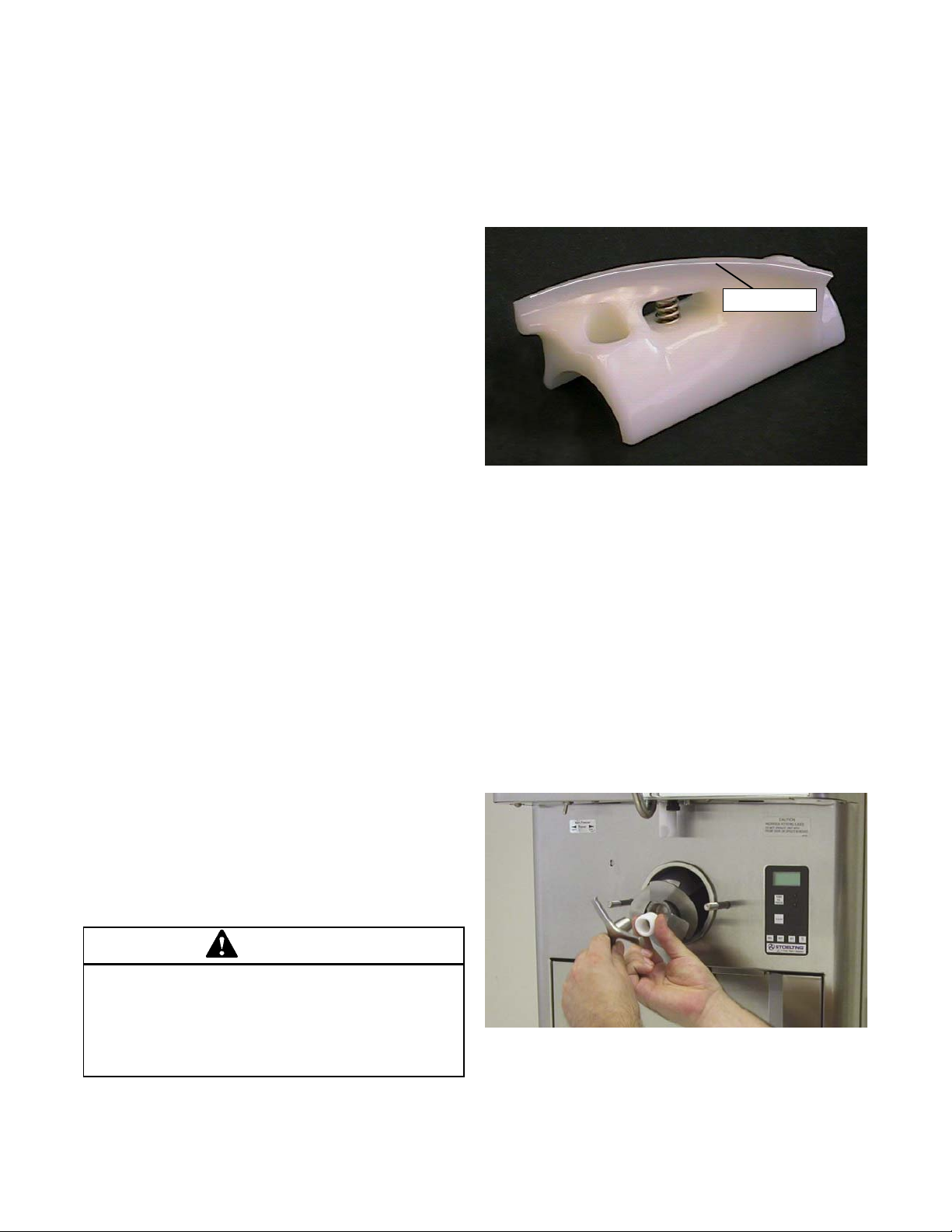
Inspection for worn or broken parts should be made each
time the machine is disassembled. All worn or broken parts
should be replaced to ensure safety to both the operator and
the customer and to maintain good machine performance
and a quality product. Check the wear line on the auger
flights on a regular basis (Fig. 3-6) and replace as needed.
Frequency of cleaning must comply with the local health
regulations.
Wear Line
Figure 3-6 Auger Flight Wear
To disassemble the machine, refer to the following steps:
A. Remove hopper cover and drain tray.
B. Remove the mix inlet regulator from the hopper by
pulling straight up.
C. Remove the front door by turning the circular knobs
and then pulling the front door off the studs.
D. Remove the rosette cap from the front door. Push
the spigot body through the bottom of the front door
and remove.
E. Remove the front auger support and bushing (Fig.
3-7).
3.4 DISASSEMBLY OF PARTS
WARNING
Hazardous Moving Parts
Revolving auger shaft can grab and cause injury.
Place the Main Freezer Power OFF-ON switch in
the OFF position before disassembling for cleaning
or servicing.
Figure 3-7 Removing Auger Support
12
 Loading...