

Stoelting M202B W/C Installation Manual

Model M202 IntelliTec™
OPERATORS MANUAL
Manual No. 513666 Rev.1

This manual provides basic information about the machine. Instructions and suggestions are
given covering its operation and care.
The illustrations and specifi cations are not binding in detail. We reserve the right to make
changes to the machine without notice, and without incurring any obligation to modify or provide new parts for machines built prior to date of change.
DO NOT ATTEMPT to operate the machine until instructions and safety precautions in this
manual are read completely and are thoroughly understood. If problems develop or questions
arise in connection with installation, operation, or servicing of the machine, contact Stoelting.
stoeltingfoodservice.com
Stoelting Foodservice Equipment
502 Highway 67
Kiel, WI 53042-1600
U.S.A.
Main Tel: 800.558.5807
Fax: 920.894.7029
Customer Service: 888.429.5920
Fax: 800.545.0662
Email: foodservice@stoelting.com
© 2014 PW Stoelting, LLC
A Few Words About Safety
Safety Information
Read and understand the entire manual before
operating or maintaining Stoelting equipment.
This manual provides the operator with information
for the safe operation and maintenance of Stoelting
equipment. As with any machine, there are hazards
associated with their operation. For this reason safety
is emphasized throughout the manual. To highlight
specifi c safety information, the following safety defi ni-
tions are provided to assist the reader.
The purpose of safety symbols is to attract your attention to possible dangers. The safety symbols, and
their explanations, deserve your careful attention
and understanding. The safety warnings do not by
themselves eliminate any danger. The instructions
or warnings they give are not substitutes for proper
accident prevention measures.
If you need to replace a part, use genuine Stoelting
parts with the correct part number or an equivalent
part. We strongly recommend that you do not use
replacement parts of inferior quality.
Safety Alert Symbol:
This symbol Indicates danger, warning or caution.
Attention is required in order to avoid serious personal injury. The message that follows the symbol
contains important information about safety.
Signal Word:
Signal words are distinctive words used throughout
this manual that alert the reader to the existence and
relative degree of a hazard.
WARNING
The signal word “WARNING” indicates a potentially
hazardous situation, which, if not avoided, may result
in death or serious injury and equipment/property
damage.
CAUTION
The signal word “CAUTION” indicates a potentially
hazardous situation, which, if not avoided, may result
in minor or moderate injury and equipment/property
damage.
CAUTION
The signal word “CAUTION” not preceded by the
safety alert symbol indicates a potentially hazardous
situation, which, if not avoided, may result in equipment/property damage.
NOTE (or NOTICE)
The signal word “NOTICE” indicates information or
procedures that relate directly or indirectly to the
safety of personnel or equipment/property.

TABLE OF
CONTENTS
Section Description Page
1 Description and Specifi cations
1.1 Description ..................................................................................................1
1.2 Specifi cations .............................................................................................2
2 Installation Instructions
2.1 Safety Precautions .....................................................................................3
2.2 Receiving the Custard Machine ..................................................................3
2.3 Machine Installation ....................................................................................3
A. Running Line Sets ................................................................................................3
B. Running Electrical Connections ...........................................................................4
C. Plumbing Connections .........................................................................................4
D. Receiving and Installing Remote Condensing Units ............................................5
E. Setting in Place and Making Machine Connections .............................................5
F. Running Product and Setting Pressures ..............................................................6
3 Initial Set-Up and Operation
3.1 Operator’s Safety Precautions ....................................................................9
3.2 Operating Controls and Indicators ..............................................................9
3.3 Sanitizing ....................................................................................................10
3.4 Freeze Down and Operation ......................................................................11
3.5 Mix Information ...........................................................................................12
3.6 Removing Mix from Machine ......................................................................12
3.7 Cleaning the Machine .................................................................................12
3.8 Disassembly of Machine Parts ...................................................................13
3.9 Cleaning the Machine Parts .......................................................................13
3.10 Assembly of Machine .................................................................................13
3.11 Routine Cleaning ........................................................................................14
3.12 Preventative Maintenance ..........................................................................14
3.13 Extended Storage .......................................................................................15
4 Troubleshooting
4.1 Error Codes ................................................................................................17
4.2 Troubleshooting Error Codes ......................................................................17
4.3 Troubleshooting Tables ...............................................................................19
5 Replacement Parts
5.1 Decals and Lubrication ...............................................................................21
5.2 Auger Shaft and Faceplate Parts ...............................................................22
5.3 Hopper Parts ..............................................................................................23

SECTION 1
DESCRIPTION AND SPECIFICATIONS
1.1 DESCRIPTION
The M202 is continuous fl ow custard machine. It is
equipped with fully automatic controls to provide a uniform product and feature Quick-Freeze technology . This
manual is designed to assist qualifi ed service personnel
and operators in the installation, operation and maintenance of the M202 frozen custard machine.
NOTE
Product breakdown could happen quicker if product
is stored in the freezing cylinders for more than one
hour. After a batch is made, close the fl ow control
and empty the contents of the freezing cylinder.
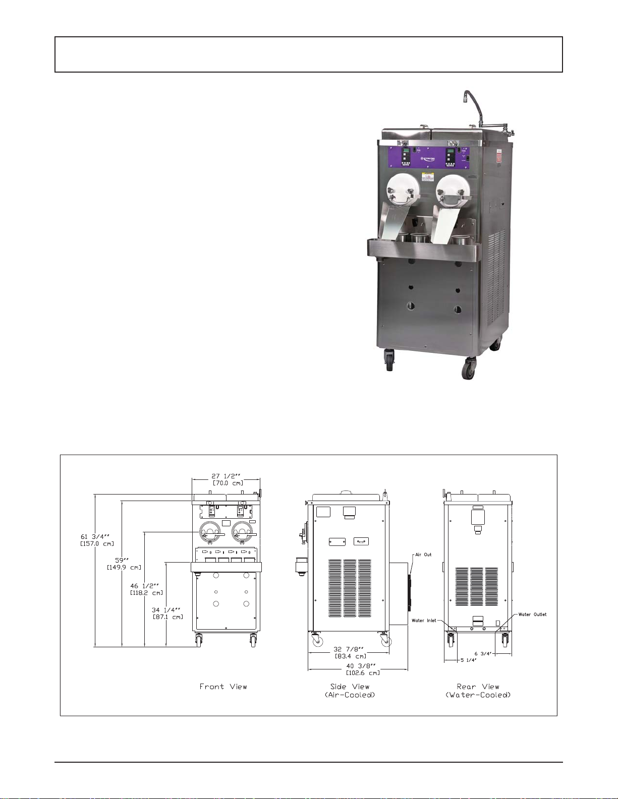
Figure 1-1 Model M202
Figure 1-2 Model M202 Dimensions
Owner’s Manual #513666 Rev.1 1 M202B Model Machines
1.2 SPECIFICATIONS
Dimensions
M202B A/C M202B A/C Remote M202B W/C
Machine with crate Machine with crate Machine with crate
width
height
depth
Weight
Electrical
circuit ampacity
(per barrel)
overcurrent protection
device (per barrel)
27-1/2’’
(69,9 cm)
59’’
(149,9 cm)
40-3/8’’
(102,6 cm)
845 lbs
(383,2 kg)
1 PH 3 PH 1 PH 3 PH 1 PH 3 PH
20A 15A 15A 15A 20A 15A
25A 15A 15A 15A 25A 15A
48’’
(121,9 cm)
69-1/4’’
(175,9 cm)
60’’
(152,4 cm)
1100 lbs
(498,9 kg)
27-1/2’’
(69,9 cm)
57-1/2’’
(146,1 cm)
32’’
(81,3 cm)
645 lbs
(292,5 kg)
Drive Motor Two - 2 hp
Air cooled units require one
remote condensing unit
(with compressor) per barrel.
Condensing units #285090
and #285091 ship from the
factory with 20 lbs of R-404A
for up to a 50’ line set. Add
1 lb of refrigerant for every
10’ increase to the line set.
Line set max 100’. (Remote
condensers CU-0050 and CU-
0060 do not ship charged and
require 20 lbs of R-404A)
Cooling
Self contained air cooled units
require 6” (15,2 cm) air space
on sides and 24” (60,9 cm) at
the back. They are charged
with R-404A.
42-1/2’’
(108,0 cm)
67’’
(170,2 cm)
48’’
(121,9 cm)
945 lbs
(428,6 kg)
27-1/2’’
(69,9 cm)
57-1/2’’
(146,1 cm)
32’’
(81,3 cm)
845 lbs
(383,2 kg)
Water cooled units are self
contained and require a
Standard Hose Adapter water
fi tting and a 1/2” OD drain
fi tting for each barrel. They are
charged with R-404A.
42-1/2’’
(108,0 cm)
67’’
(170,2 cm)
48’’
(121,9 cm)
1100 lbs
(498,9 kg)
Hopper Volume Two - 5.4 gallon (20,57 liters)
Remote Condensing Unit (1 per barrel)
Dimensions Condenser
width 37-3/4’’ (95,9 cm)
height 17-1/4’’ (43,7 cm)
depth 28-1/4’’ (71,7 cm)
Weight 222 lbs (100,7 kg)
Electrical
circuit ampacity
overcurrent protection
device
Refrigerant R-404A
Charge 20 lbs. (Charged at Factory)
Refrigerated Line
Sizes
Owner’s Manual #513666 Rev.1 2 M202B Model Machines
1 Phase, 208-230 VAC, 60Hz 3 Phase, 208-230 VAC, 60Hz
20A minimum 15A minimum
25A maximum 20A maximum
Liquid Line - 3/8”
Suction Line - 5/8”
SECTION 2
INSTALLATION INSTRUCTIONS
2.1 SAFETY PRECAUTIONS
Do not attempt to operate the machine until the safety
precautions and operating instructions in this manual are
read completely and are thoroughly understood.
Take notice of all warning labels on the machine. The labels have been put there to help maintain a safe working
environment. The labels have been designed to withstand
washing and cleaning. All labels must remain legible for
the life of the machine. Labels should be checked periodically to be sure they can be recognized as warning labels.
If danger, warning or caution labels are needed, indicate
the part number, type of label, location of label, and quantity
required along with your address and mail to:
STOELTING
ATTENTION: Customer Service
502 Hwy. 67
Kiel, Wisconsin 53042
2.2 RECEIVING THE CUSTARD MACHINE
A. Upon arrival, check the entire machine for any
damage that may have occurred during transit.
With the method of packaging used, the machine
should arrive in excellent condition. The carrier
is responsible for all damage in transit, whether
visible or concealed. Do not pay the freight bill
until the machine has been checked for damage.
Have the carrier note any visible damage on the
freight bill. If concealed damage or a shortage is
found later, advise the carrier within 10 days and
request inspection. The customer must place a
claim for damages and/or shortages in shipment
with the carrier. Stoelting cannot make any claims
against the carrier.
B. Remove the top of the crate using a hammer or
pry bar.
C. Remove the eight lag bolts from the machine
using a 1/2” ratchet. Remove the front and rear
crate walls.
D. Remove the four lag bolts located inside the left
and right crate walls using 1/2” ratchet. Remove
the left and right crate walls.
E. Remove the plastic wrapping on the machine.
Remove the lower front and back panel on the
machine.
F . Remove the four lag bolts located inside machine
on the frame with a 9/16” ratchet. Remove the
two lag bolts that hold the skid together with a
9/16” socket.
G. If the machine has the shipping casters or if it is
water-cooled, the casters will be in a box located
in the hopper pan. A set of casters includes two
casters with locks and two casters without locks.
Screw the casters into the threaded holes and
tighten them using a pair of channel locks. After
installing the casters, knock out bottom 4” x 4” of
the machine skid.
NOTE
If the machine does not come with casters, install
the stainless steel legs. The legs are located in the
hopper pan on top of the machine. After installing
the legs, use a pallet jack to move machine into
place.
H. Put front and back panels on the machine.
2.3 MACHINE INSTALLATION
The following instructions are intended for a qualifi ed
electrician/refrigeration specialist. Do not attempt these
procedures unless you are qualifi ed.
CAUTION
Installation MUST be completed by a qualifi ed
electrician/refrigeration specialist
Incorrect installation may cause personal injury,
severe damage to the machine and will void factory warranty.
A. RUNNING LINE SETS
NOTE
If the machine is water-cooled, proceed to “B. Running Electrical Connections”.
Line sets are not supplied with the machine.
The lines sets can be installed prior to receiving the
custard machine.
1 An air-cooled machine requires a remote
condensing unit and line set for each freezing
cylinder. The line sets must be 3/8” for the liquid
line and 5/8” for the suction line. When running
the line sets, each 10’ of vertical rise, install a
p-trap in the suction line. For every horizontal
line set run, pitch the suction line towards the
compressor to assist with oil returning back to
the compressor.
2 After the line set is installed, perform a thorough
leak test. Malfunctions of the equipment due
to leaks in the line set are not covered by the
Stoelting/Ross warranty.
Owner’s Manual #513666 Rev.1 3 M202B Model Machines

3 Insulate the suction line with a minimum of 3/8” wall
thickness or the wall thickness required by local
code. In humid areas, use thicker insulation. In
areas that are exposed to extreme temperatures,
insulate the liquid line to prevent excessive
sub cooling or heating of the liquid refrigerant.
Fasten all lines securely along ceilings, walls
and roofs. Avoid creating any type of kink in the
lines. The Stoelting/Ross warranty does not cover
malfunctions or capacity issues with equipment
caused by kinks in the line sets.
4 Use good piping practices when installing line sets.
Seal the ends of the line sets during installation to
prevent exposure to the atmosphere and foreign
objects. Blow the lines out with dry nitrogen to
remove any debris that might be in the line sets.
When running line sets through a wall or roof,
mark the lines to eliminate confusion as to which
line set is running to which cylinder.
Example: Mark the liquid and suction lines with
the respective cylinder number. Facing the front
of the machine, cylinders are numbered left to
right.
5 When brazing the joints, purge dry nitrogen
through the lines to minimize oxidation of copper
inside of the lines. The Stoelting/Ross warranty
does not cover problems with the refrigeration
system that are caused by oxidized material in
the lines.
B. RUNNING ELECTRICAL CONNECTIONS
1 The machine requires a separate electrical
connection for each freezing cylinder. Refer to the
nameplate on the machine for proper electrical
supply. Each freezing cylinder has its own
electrical system and condenser so if one cylinder
fails, the other cylinder will still be operational.
NOTE
An air-cooled machine needs two circuits for each
freezing cylinder, one for the remote condensing
unit and one for the freezing cylinder.
4 Do not turn on the power to the machine or
the condensing unit until the refrigeration lines
have been connected and the system has been
charged with refrigerant. Label the circuit breakers
with information regarding which cylinder and
condensing unit the breaker is designated for to
prevent confusion if power ever needs to be shut
off.
5 When connecting power to the machine, run the
line under the machine and through the bottom
of the electrical box. Remove the electrical box
cover by loosening the four screws. The screws
do not have to be removed. Connect the power
to the terminal strip. The terminal strip is labeled
L1, L2, L3, and GND. After connections are made,
place the cover on the electrical box, but do not
tighten the cover (for single-phase machines the
cover can be tightened). The electrical box may
need to be accessed when checking for proper
rotation of the motor.
C. PLUMBING CONNECTIONS
1 On water-cooled machines, the water inlet is a
standard garden hose connection and the water
outlet is 5/8” OD copper tubing. The connections
are located at the back of the machine. Remove
the rear panel to access the connections. Run
the plumbing under the machine frame. Watercooled machines use approximately 3 gallons of
75°F water per minute when the compressor is
operating. The machine does not use any water
when not in use.
2 The machine is equipped with a dipping trough
that requires a water inlet line and a drain line.
The water inlet has 1/2” NPT close nipple fi tting.
Install a shutoff valve in the water inlet line. The
drain connection is 1-1/2”. Run a drain line from
the trough to a drain on the fl oor. Leave enough
slack in the drain line so that the lower front panel
can be easily removed for service.
A water-cooled machine needs one circuit for each
freezing cylinder.
2 The electrical boxes are located behind the lower
front panel. Labels indicate which cylinder each
electrical box powers. No pigtails are supplied
with the machine or condensing unit.
3 If the condensing unit is on the roof or ground,
a quick disconnect box needs to be installed to
provide power.
Owner’s Manual #513666 Rev.1 4 M202B Model Machines
 Loading...