

Page 1

Model M202-109A, -209A
OPERATORS MANUAL
Manual No. 513614-1 Rev.5
Page 2

Page 3

This manual provides basic information about the machine. Instructions and suggestions are
given covering its operation and care.
The illustrations and specifi cations are not binding in detail. We reserve the right to make
changes to the machine without notice, and without incurring any obligation to modify or provide new parts for machines built prior to date of change.
DO NOT ATTEMPT to operate the machine until instructions and safety precautions in this
manual are read completely and are thoroughly understood. If problems develop or questions
arise in connection with installation, operation, or servicing of the machine, contact Stoelting.
stoeltingfoodservice.com
Stoelting Foodservice Equipment
502 Highway 67
Kiel, WI 53042-1600
U.S.A.
Main Tel: 800.558.5807
Fax: 920.894.7029
Customer Service: 888.429.5920
Fax: 800.545.0662
Email: foodservice@stoelting.com
© 2014 PW Stoelting, LLC
Page 4

A Few Words About Safety
Safety Information
Read and understand the entire manual before
operating or maintaining Stoelting equipment.
This manual provides the operator with information
for the safe operation and maintenance of Stoelting
equipment. As with any machine, there are hazards
associated with their operation. For this reason safety
is emphasized throughout the manual. To highlight
specifi c safety information, the following safety defi ni-
tions are provided to assist the reader.
The purpose of safety symbols is to attract your attention to possible dangers. The safety symbols, and
their explanations, deserve your careful attention
and understanding. The safety warnings do not by
themselves eliminate any danger. The instructions
or warnings they give are not substitutes for proper
accident prevention measures.
If you need to replace a part, use genuine Stoelting
parts with the correct part number or an equivalent
part. We strongly recommend that you do not use
replacement parts of inferior quality.
Safety Alert Symbol:
This symbol Indicates danger, warning or caution.
Attention is required in order to avoid serious personal injury. The message that follows the symbol
contains important information about safety.
Signal Word:
Signal words are distinctive words used throughout
this manual that alert the reader to the existence and
relative degree of a hazard.
WARNING
The signal word “WARNING” indicates a potentially
hazardous situation, which, if not avoided, may result
in death or serious injury and equipment/property
damage.
CAUTION
The signal word “CAUTION” indicates a potentially
hazardous situation, which, if not avoided, may result
in minor or moderate injury and equipment/property
damage.
CAUTION
The signal word “CAUTION” not preceded by the
safety alert symbol indicates a potentially hazardous
situation, which, if not avoided, may result in equipment/property damage.
NOTE (or NOTICE)
The signal word “NOTICE” indicates information or
procedures that relate directly or indirectly to the
safety of personnel or equipment/property.
Page 5

TABLE OF
CONTENTS
Section Description Page
1 Description and Specifi cations
1.1 Description ..................................................................................................1
1.2 Specifi cations .............................................................................................2
2 Installation Instructions
2.1 Safety Precautions .....................................................................................3
2.2 Receiving the Custard Machine ..................................................................3
2.3 Machine Installation ....................................................................................3
A. Running Line Sets ................................................................................................3
B. Running Electrical Connections ...........................................................................4
C. Plumbing Connections .........................................................................................4
D. Receiving and Installing Remote Conendsing Units ............................................5
E. Setting in Place and Making Machine Connections .............................................5
F. Running Product and Setting Pressures for the Custard Machine.......................6
3 Initial Set-Up and Operation
3.1 Operator’s Safety Precautions ....................................................................9
3.2 Operating Controls and Indicators ..............................................................9
3.3 Sanitizing ....................................................................................................10
3.4 Freeze Down and Operation ......................................................................10
3.5 Mix Information ...........................................................................................11
3.6 Hold Cycle During Operation ......................................................................11
3.7 Production After Hold Cycle ........................................................................11
3.8 Removing Mix .............................................................................................11
3.9 Cleaning the Machine .................................................................................12
3.10 Disassembly of Machine Parts ...................................................................12
3.11 Cleaning the Machine Parts .......................................................................12
3.12 Assembly of Machine .................................................................................12
3.13 Routine Cleaning ........................................................................................13
3.14 Preventative Maintenance ..........................................................................13
3.15 Extended Storage .......................................................................................15
4 Troubleshooting
4.1 Troubleshooting the Machine .....................................................................17
4.2 Troubleshooting the Hopper .......................................................................18
4.3 Troubleshooting the Dipping Cabinet .........................................................18
5 Replacement Parts
5.1 Decals and Lubrication ...............................................................................19
5.2 Auger Shaft and Faceplate Parts ...............................................................20
5.3 Hopper Parts ..............................................................................................21
Page 6

Page 7
SECTION 1
DESCRIPTION AND SPECIFICATIONS
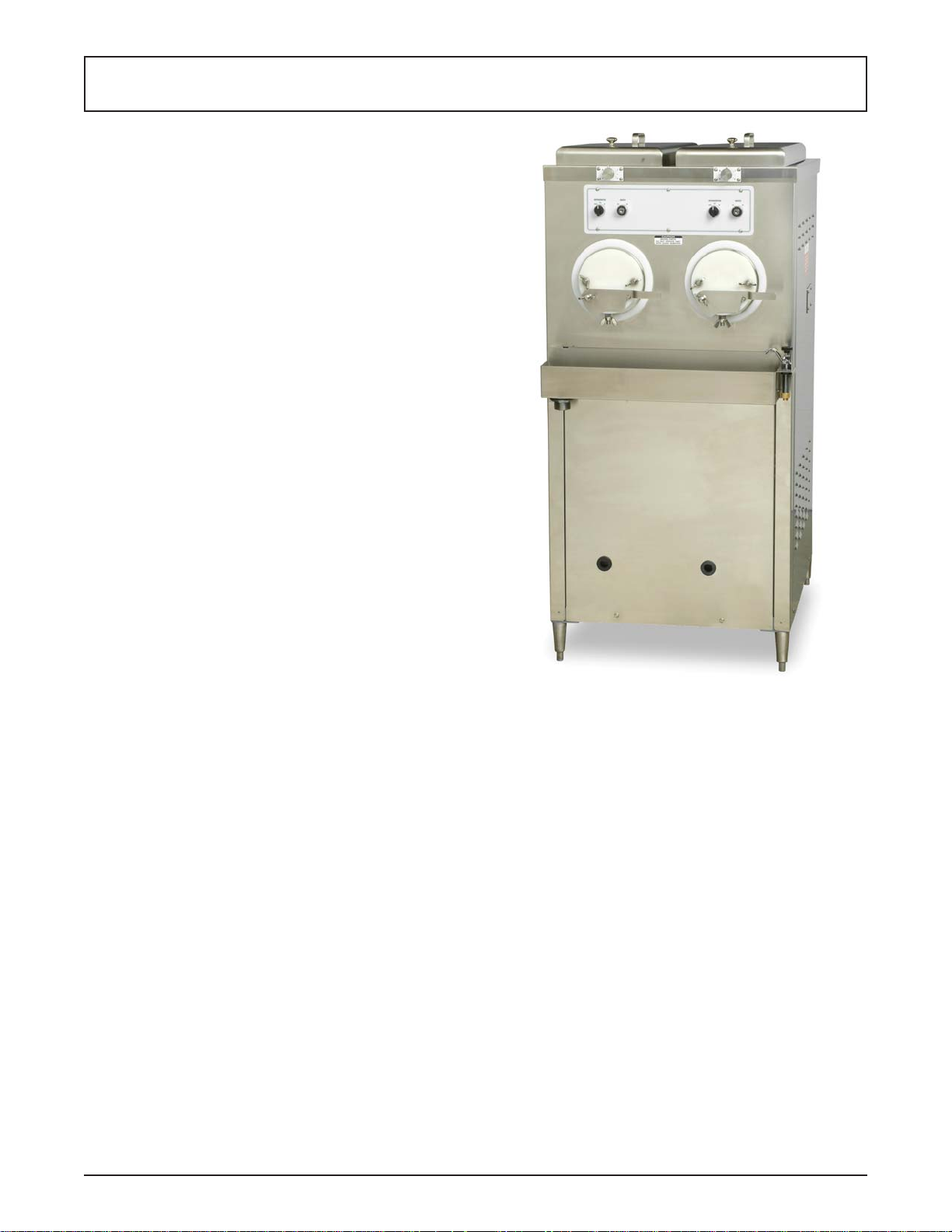
1.1 DESCRIPTION
The M202 is a frozen custard machine. It is equipped
with fully automatic controls to provide a uniform product
and features Quick-Freeze technology. This manual is
designed to assist qualifi ed service personnel and opera-
tors in the installation, operation and maintenance of the
M202 frozen custard machine.
Figure 1-1 Model M202A
Owner’s Manual #513614-1 1 M202 Model Machines
Page 8
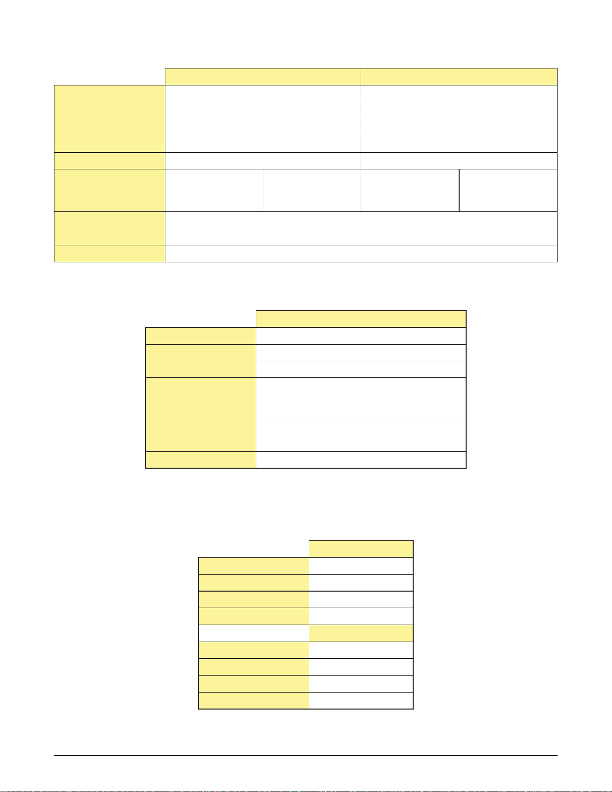
1.2 SPECIFICATIONS
Dimensions
width
height
depth
Weight
Electrical
breaker size per barrel
Hopper Condenser
Drive Motor
M202 Air Cooled M202 Water Cooled
Machine with crate Machine with crate
27-1/2’’ (69,9 cm) 42-1/2’’ (108,0 cm) 27-1/2’’ (69,9 cm) 42-1/2’’ (108,0 cm)
57-1/2’’ (146,1 cm) 67’’ (170,2 cm) 57-1/2’’ (146,1 cm) 67’’ (170,2 cm)
32’’ (81,3 cm) 48’’ (121,9 cm) 32’’ (81,3 cm) 48’’ (121,9 cm)
645 lbs (292,5 kg) 945 lbs (428,6 kg) 845 lbs (383,2 kg) 1100 lbs (498,9 kg)
1 Phase, 208-240
VAC, 60Hz
20A 15A 30A 20A
3 Phase, 208-240
VAC, 60Hz
1 Phase, 115 VAC, 60Hz
20A Breaker
Two - 2 hp
1 Phase, 208-240
VAC, 60Hz
3 Phase, 208-240
VAC, 60Hz
M202*
Refrigerant R-404A
Charge 24 lbs
AXV 28-32 psig
Head Pressure
Regulator (Water
255 psig
Valve)
Crankcase Pressure
Regulator
25 psig
Lemon Ice AXV 38-42 psig
* There is a separate refrigeration system for each freezing cylinder. The
refrigeration specifi cations are per freezing cylinder.
Hopper
F/C F
Temp 36 °F
Diff 1
Mode C1
Hold Cycle
F/C F
Temp 38 °F
Diff 1
Mode C1
Owner’s Manual #513614-1 2 M202 Model Machines
Page 9

SECTION 2
INSTALLATION INSTRUCTIONS
2.1 SAFETY PRECAUTIONS
Do not attempt to operate the machine until the safety
precautions and operating instructions in this manual are
read completely and are thoroughly understood.
Take notice of all warning labels on the machine. The labels have been put there to help maintain a safe working
environment. The labels have been designed to withstand
washing and cleaning. All labels must remain legible for
the life of the machine. Labels should be checked periodically to be sure they can be recognized as warning labels.
If danger, warning or caution labels are needed, indicate
the part number, type of label, location of label, and quantity
required along with your address and mail to:
STOELTING, INC.
ATTENTION: Customer Service
502 Hwy. 67
Kiel, Wisconsin 53042
2.2 RECEIVING THE CUSTARD MACHINE
A. Upon arrival, check the entire machine for any
damage that may have occurred during transit.
With the method of packaging used, the machine
should arrive in excellent condition. The carrier
is responsible for all damage in transit, whether
visible or concealed. Do not pay the freight bill
until the machine has been checked for damage.
Have the carrier note any visible damage on the
freight bill. If concealed damage or a shortage is
found later, advise the carrier within 10 days and
request inspection. The customer must place a
claim for damages and/or shortages in shipment
with the carrier. Stoelting cannot make any claims
against the carrier.
B. Remove the top of the crate using a hammer or
pry bar.
C. Remove the eight lag bolts from the machine
using a 1/2” ratchet. Remove the front and rear
crate walls.
D. Remove the four lag bolts located inside the left
and right crate walls using 1/2” ratchet. Remove
the left and right crate walls.
E. Remove the plastic wrapping on the machine.
Remove the lower front and back panel on the
machine.
F . Remove the four lag bolts located inside machine
on the frame with a 9/16” ratchet. Remove the
two lag bolts that hold the skid together with a
9/16” socket.
G. If the machine has the shipping casters or if it is
water-cooled, the casters will be in a box located
in the hopper pan. A set of casters includes two
casters with locks and two casters without locks.
Screw the casters into the threaded holes and
tighten them using a pair of channel locks. After
installing the casters, knock out bottom 4” x 4” of
the machine skid.
NOTE
If the machine does not come with casters, install
the stainless steel legs. The legs are located in the
hopper pan on top of the machine. After installing
the legs, use a pallet jack to move machine into
place.
H. Put front and back panels on the machine.
2.3 MACHINE INSTALLATION
The following instructions are intended for a qualifi ed
electrician/refrigeration specialist. Do not attempt these
procedures unless you are qualifi ed.
CAUTION
Installation MUST be completed by a qualifi ed
electrician/refrigeration specialist
Incorrect installation may cause personal injury,
severe damage to the machine and will void factory warranty.
A. RUNNING LINE SETS
NOTE
If the machine is water-cooled, proceed to “B. Running Electrical Connections”.
Line sets are not supplied with the machine.
The lines sets can be installed prior to receiving the
custard machine.
1 An air-cooled machine requires a remote
condensing unit and line set for each freezing
cylinder. The line sets must be 3/8” for the liquid
line and 5/8” for the suction line. When running
the line sets, each 10’ of vertical rise, install a
p-trap in the suction line. For every horizontal
line set run, pitch the suction line towards the
compressor to assist with oil returning back to
the compressor.
2 After the line set is installed, perform a thorough
leak test. Malfunctions of the equipment due
to leaks in the line set are not covered by the
Stoelting/Ross warranty.
Owner’s Manual #513614-1 3 M202 Model Machines
Page 10

3 Insulate the suction line with a minimum of 3/8” wall
thickness or the wall thickness required by local
code. In humid areas, use thicker insulation. In
areas that are exposed to extreme temperatures,
insulate the liquid line to prevent excessive
sub cooling or heating of the liquid refrigerant.
Fasten all lines securely along ceilings, walls
and roofs. Avoid creating any type of kink in the
lines. The Stoelting/Ross warranty does not cover
malfunctions or capacity issues with equipment
caused by kinks in the line sets.
4 Use good piping practices when installing line sets.
Seal the ends of the line sets during installation to
prevent exposure to the atmosphere and foreign
objects. Blow the lines out with dry nitrogen to
remove any debris that might be in the line sets.
When running line sets through a wall or roof,
mark the lines to eliminate confusion as to which
line set is running to which cylinder.
Example: Mark the liquid and suction lines with
the respective cylinder number. Facing the front
of the machine, cylinders are numbered left to
right.
5 When brazing the joints, purge dry nitrogen
through the lines to minimize oxidation of copper
inside of the lines. The Stoelting/Ross warranty
does not cover problems with the refrigeration
system that are caused by oxidized material in
the lines.
B. RUNNING ELECTRICAL CONNECTIONS
1 The machine requires a separate electrical
connection for each freezing cylinder. Refer to the
nameplate on the machine for proper electrical
supply. Each freezing cylinder has its own
electrical system and condenser so if one cylinder
fails, the other cylinder will still be operational.
NOTE
An air-cooled machine needs two circuits for each
freezing cylinder, one for the remote condensing
unit and one for the freezing cylinder.
A water-cooled machine needs one circuit for each
freezing cylinder.
2 The electrical boxes are located behind the lower
front panel. Labels indicate which cylinder each
electrical box powers. No pigtails are supplied
with the machine or condensing unit.
3 If the condensing unit is on the roof or ground,
a quick disconnect box needs to be installed to
provide power.
4 Do not turn on the power to the machine or
the condensing unit until the refrigeration lines
have been connected and the system has been
charged with refrigerant. Label the circuit breakers
with information regarding which cylinder and
condensing unit the breaker is designated for to
prevent confusion if power ever needs to be shut
off.
5 When connecting power to the machine, run the
line under the machine and through the bottom of
the electrical box. Remove the electrical box cover
by loosening the four screws. The screws do not
have to be removed. Connect the power to the
4-circuit terminal strip. The 4-circuit terminal strip
is labeled L1, L2, L3, and GND. After connections
are made, place the cover on the electrical box,
but do not tighten the cover (for single-phase
machines the cover can be tightened). The
electrical box may need to be accessed when
checking for proper rotation of the motor.
C. PLUMBING CONNECTIONS
1 On water-cooled machines, the water inlet is a
standard garden hose connection and the water
outlet is 5/8” OD copper tubing. The connections
are located at the back of the machine. Remove
the rear panel to access the connections. Run
the plumbing under the machine frame. Watercooled machines use approximately 2 gallons of
75°F water per minute while in use. The machine
does not use any water when not in use.
2 The machine is equipped with a dipping trough
that requires a water inlet line and a drain line.
The water inlet has a 1/4” OD brass female
connector. Solder a 1/4” line to the water valve
inlet using silver solder. Install a shutoff valve in
the water inlet line. The drain connection is 1-1/2”.
Run a drain line from the trough to a drain on the
fl oor . Leave enough slack in the drain line so that
the lower front panel can be easily removed for
service.
3 If the machine is equipped with the hopper faucet
option, run the hopper faucet tubing to the dipping
trough inlet and install a T. This will supply water
needed for the hopper faucet and the water valve
for the dipping trough.
Owner’s Manual #513614-1 4 M202 Model Machines
Page 11

D. RECEIVING AND INSTALLING REMOTE
CONDENSING UNITS
NOTE
The remote condensing units may be sent prior to
delivery of the freezer.
The freezer requires one remote condensing unit
per cylinder.
1 Upon arrival, check the entire remote condenser
units for any damage that may have occurred
during transit. With the method of packaging used,
the remote condensers should arrive in excellent
condition. The carrier is responsible for all damage
in transit, whether visible or concealed. Do not
pay the freight bill until the remote condenser
units have been checked for damage. Have the
carrier note any visible damage on the freight
bill. If concealed damage or a shortage is found
later, advise the carrier within 10 days and request
inspection. The customer must place a claim for
damages and/or shortages in shipment with the
carrier. Stoelting cannot make any claims against
the carrier.
2 Remove cardboard covering off the condensing
units.
3 Place the condensing units in their predetermined
location, either on the roof or on the ground. A
crane or forklift will be needed if the units will be
placed on a roof. The condensing units weigh
approximately 200 lbs. each.
4 Using ratchet with a 1/2” socket, remove the two
lag bolts that secure the condensing unit to the
pallet.
5 Place the condensing units on 4” x 4” treated
wood or similar material so that the units are not
sitting directly on the ground or the roof. Secure
the condensing units to the 4” x 4” using lag
bolts. Adhere to all local, state, and federal codes
governing this type of installation. Some areas
have specifi c “hurricane-proof” requirements
for roof installations. Allow at least 2 feet of
clearance on the air intake and discharge sides
of the condensers. Do not set the condensers
so that one is blowing air directly into the other
condensing unit. The ideal set up is to have all
the condensing units set in a row (Fig. 2-1).
6 Use an Allen wrench to open the shut off valves
and release some of the nitrogen charge in the
condensing unit. The shut off valves are located on
the outside of the condensing unit. If no nitrogen
is present then the unit needs to be leak checked
prior to connecting the refrigeration lines.
7 Braze the suction line and liquid line from the line
sets to the condensing unit. When brazing, wrap
the shut off valve with a cold wet rag and make
sure that the valve is fully open. If valve is not
wrapped, damage to the valve may result. When
installing the suction line, angle it towards the
condensing unit so that oil can fl ow back towards
the compressor.
8 Use good piping practices. Keep pipes as clean as
possible. Do not let any debris or copper shavings
get inside system otherwise the refrigeration
valves may not work properly.
E. SETTING IN PLACE AND MAKING MACHINE
CONNECTIONS
1 Roll the machine into the desired location. Leave
adequate space around the machine for the
removal of service panels. Remove the left, right,
back and lower front service panels.
NOTE
After the refrigeration lines are connected, aircooled machines cannot be moved.
2 Use a pallet jack or fl oor jack to lift the front of the
machine, remove the two shipping casters with
a pair of channel locks, and install the stainless
steel legs. Make sure the legs are adjusted all the
way in, and screw two of the legs into the frame.
Secure them tightly using channel locks. Repeat
with the back of the machine.
NOTE
If the machine is water-cooled, casters are standard
with machine.
3 Accurate leveling is necessary to ensure
proper operation. Place a bubble level on top
of the machine at each corner to check for level
condition. If adjustment is necessary, level the
machine by turning the bottom part of each leg
or caster in or out.
To fi nish installing a water-cooled machine,
proceed to “G. Running product and setting
pressures for the custard machine”.
Figure 2-1 Remote Condenser Installation
(Top View)
Owner’s Manual #513614-1 5 M202 Model Machines
Page 12

4 Connect the refrigeration lines from the line sets
to the machine. Access the machine from the left
or right service panel. The refrigeration system
has a charge of dry nitrogen. Use caution when
connecting the lines. Connect the suction line fi rst
then connect the liquid line. Run the refrigeration
lines under the machine. There is approximately
6” of clearance between machine and the fl oor.
The stainless steel legs are adjustable and can
raise the machine up to 7” off the fl oor if necessary .
Wrap the suction solenoid in a cold wet rag when
soldering to prevent damage to the solenoid. Also,
be aware of the electrical conduit inside custard
machine while soldering the refrigeration lines.
A liquid line dryer is supplied with the machine
and should be the last connection made in the
system. Use good piping techniques to keep the
system clean. Do not leave the lines open and
exposed for a long period.
5 After fi nishing the refrigeration connections,
connect power to the machine. Refer to
“B. Running Electrical Lines” for the proper
procedures. Check the rotation of the beater
shaft. When looking at the machine from the
front, the shaft needs to turn counterclockwise.
If the shaft is turning the wrong direction, shut off
power to the cylinder and switch the L1 and L3
wires. Check rotation again to verify the shaft is
rotating counterclockwise. Once verifi ed, tighten
the screws on the electrical box cover.
If the machine is single phase and the beater
shaft rotation is clockwise, then complete one
of the following procedures. Check rotation after
each procedure.
A. Change programming on variable speed drive
to reverse motor.
B. Change the T1 and T3 output leads going to
the motor from the drive.
C. Change the leads inside the motor electrical
box.
6 Check the refrigeration systems for leaks. When
pressurizing the system, turn the refrigeration
switch to hold position to energize the suction
solenoid. Also, make sure that the shut of f valves
are open on the remote condensing unit. Check
the refrigeration system with a minimum of 100
psi. Make sure the system will hold the pressure
for a minimum of 2 hours.
7 After the leak check, connect a vacuum pump to
the system and evacuate it to 500 microns for a
minimum of 1 hour. Make sure the suction solenoid
and the shut off valves on the condensing unit
are opened. Perform a standing vacuum test. If
the vacuum deteriorates and continues to rise
there is a leak. Find it, repair it, and repeat the
evacuation procedure until the machine passes
a standing vacuum test. While the refrigeration
system is under a vacuum, insulate the suction
line. Insulation is needed up to the shut off valve
on the condensing unit. Use 3/8” tube insulation
or insulation required by local code.
8 Use good refrigeration practices to charge the
system with the required charge. Air-cooled
machines require 20 lbs of refrigerant per cylinder
and water-cooled machines require 8 lbs of
refrigerant per cylinder. Make sure the suction
solenoid is energized and that the shut off valves
are open.
NOTE
Air-cooled machines do not ship with refrigerant
and require refrigerant to be supplied on site.
Water-cooled machines are factory charged. The
hoppers for air-cooled and water-cooled machines
are factory charged.
The charge for air-cooled machines is suffi cient for
up to a 50 ft. line set. If the line set is longer, add
1 lb. of refrigerant for every 10 ft. of additional line
(up to 150 ft. total).
F. RUNNING PRODUCT AND SETTING PRESSURES
FOR THE CUSTARD MACHINE
NOTE
Complete the Custard Machine Start-Up and T raining Checklist located with the spare parts kit or in
the back of this manual and send it to Stoelting.
1 Remove all spare parts from the hopper before
running product. Unwrap the parts and check for
damage. Refer to the list in the back of this manual
to make sure no parts are missing. The cylinders
need to be under a load to set the pressures. If
custard is not available, RV antifreeze can be
used as an alternative. Mix the RV antifreeze in a
concentration of 1 part antifreeze to 1 part water.
If RV antifreeze is used, the pressures will need
to be rechecked when custard mix is available.
The RV antifreeze will indicate that the system
is functioning correctly.
2 Disassemble, clean and sanitize each freezing
cylinder. Refer to the Section 3 for proper
instructions.
Owner’s Manual #513614-1 6 M202 Model Machines
Page 13

3 After assembling and sanitizing the machine, add
custard mix to the hopper. Follow the instructions in
the Section 3 to start freezing the custard (run one
cylinder at a time to set the pressures). Connect
gauges to the suction line and the discharge line.
When product starts coming out of the faceplate,
locate the low pressure gauge on the front of the
machine and set the AXV to 30 psi. Remove the
white plastic cap from the AXV and turn the valve
counterclockwise to decrease the pressure or
clockwise to increase the pressure. Turn the valve
1/4 turn at a time and wait at least 1 minute before
making another adjustment. Connect a gauge
to the suction line at the compressor and make
sure the pressure is 25 psi. Adjust the crankcase
pressure regulator (CPR) if the pressure is not
correct. Remove threaded brass cap on the front
of the CPR and adjust the valve with a 5/16” Allen
wrench. Connect a gauge to the suction line at
the hopper and adjust the hopper AXV to 55 psi.
4 Check the faceplate to see if the custard is at the
desired texture and temperature. The standard
normal serving temperature of frozen custard
coming out of the machine is 18°-21°F.
5 Set the pressures for the remaining cylinders.
NOTE
If the machine is water-cooled, the discharge pressure was already set at the factory. Run custard
mix through the machine to double-check and
fi ne-tune the discharge pressure for the particular
mix being used.
The remote condenser unit has a head pressure
control set for a minimum of 255 psi.
Chocolate and vanilla mixes run differently . Usually
the pressures in the chocolate cylinder will need to
be set slightly lower than the pressures in the vanilla
cylinder. Custard mixes that use an extract fl avor-
ing will also run differently. Try different pressure
settings by adjusting the AXV. Adjust the pressure
setting between 28-32 psi (the machine will not
operate correctly if the AXV is set lower than 28 psi).
6 If the machine is equipped with the lemon ice
option, set the lemon ice AXV . The lemon ice option
is designated for one cylinder (right cylinder).
With the system still running product, turn the
lemon ice switch on. The AXV is located behind
the cylinder in front of the machine. Set the lemon
ice AXV for 38-42 psi.
7 When testing is done, take the cylinders apart
and clean the custard machine. Refer Section 3
for details.
Owner’s Manual #513614-1 7 M202 Model Machines
Page 14

Owner’s Manual #513614-1 8 M202 Model Machines
Page 15

SECTION 3
INITIAL SET-UP AND OPERATION
3.1 OPERATOR’S SAFETY PRECAUTIONS
SAFE OPERATION IS NO ACCIDENT; observe these
rules:
A. Know the machine. Read and understand the
Operating Instructions.
B. Notice all warning labels on the machine.
C. Wear proper clothing. Avoid loose fi tting garments,
and remove watches, rings or jewelry that could
cause a serious accident.
D. Maintain a clean work area. Avoid accidents by
cleaning up the area and keeping it clean.
E. Stay alert at all times. Know which switch, push
button or control you are about to use and what
effect it is going to have.
F . Disconnect electrical cord for maintenance. Never
attempt to repair or perform maintenance on the
machine until the main electrical power has been
disconnected.
G. Do not operate under unsafe operating conditions.
Never operate the machine if unusual or excessive
noise or vibration occurs.
3.2 OPERATING CONTROLS AND INDICATORS
Before operating the machine, it is required that the operator know the function of each operating control. Refer
to Figure 3-1 for the location of the operating controls on
the machine.
WARNING
High voltage will shock, burn or cause death. The
OFF-ON switch must be placed in the OFF position
prior to disassembling for cleaning or servicing. Do
not operate machine with cabinet panels removed.
A. Refrigeration Hold/Off/On
The Refrigeration Hold/Off/On switch is a three-
position switch.
Hold - When the switch is in the Hold position,
the refrigeration system will run until the
freezing cylinder and the hopper reach a preset
temperature. The refrigeration system cycle on
and off to maintain this temperature.
Off - When the switch is in the Off position, the
refrigeration system will not cool the freezing
cylinder.
On - When the switch is in the On position and the
Beater switch is in the On position, the refrigeration
system will run continuously.
Flow Control
Knob
Beater
Off/On
Refrigeration
Hold/Off/On
Figure 3-1 Machine Controls
Owner’s Manual #513614-1 9 M202 Model Machines
Page 16

B. Beater Off/On Keyed Switch
The Beater Off/On switch controls the operation
of the beater shaft.
C. Flow Control Knob
The Flow Control Knob regulates the amount of
mix entering the freezing cylinder.
3.3 SANITIZING
Sanitizing must be done after the machine is cleaned and
just before the hopper is fi lled with mix. Sanitizing the night
before is not effective. However , you should always clean
the machine and parts after each use.
THE UNITED STATES DEPARTMENT OF AGRICUL TURE AND THE FOOD AND DRUG ADMINISTRA TION REQUIRE THA T ALL CLEANING AND
SANITIZING SOLUTIONS USED WITH FOOD
PROCESSING EQUIPMENT BE CERTIFIED FOR
THIS USE.
When sanitizing the machine, refer to local sanitary regulations for applicable codes and recommended sanitizing
products and procedures. The frequency of sanitizing
must comply with local health regulations.
Mix sanitizer according to manufacturer’s instructions to
provide a 100 parts per million strength solution. Mix sanitizer in quantities of no less than 2 gallons (7.5 liters) of
90° to 1 10°F (32° to 43°C) water. Allow sanitizer to contact
the surfaces to be sanitized for 5 minutes. Any sanitizer
must be used only in accordance with the manufacturer’s
instructions.
In general, sanitizing may be conducted as follows:
A. Prepare Stera-Sheen Green Label Sanitizer
or equivalent according to manufacturer’s
instructions to provide a 100ppm strength solution.
Mix the sanitizer in quantities of no less than 2
gallons of 90° to 110°F (32° to 43°C) water. Any
sanitizer must be used only in accordance with
the manufacturer’s instructions.
B. Place the tapered end of the fl ow valve into the
hopper drain hole with the arm pointing towards
the left. Connect the fl ow control rod to the fl ow
valve and the fl ow valve arm (Fig. 3-2).
C. Make sure the fl ow control valve is shut by turning
the control knob counterclockwise to the 12:00
position.
D. Place a bucket under the slide.
E. Pour the sanitizer into the hopper.
NOTE
A small amount of sanitizer may drain into the
bucket with the fl ow control shut.
F . Place the Beater Off/On switch in the On position.
G. Turn the fl ow control knob fully open (clockwise).
Figure 3-2 Flow Control Assembly
H. Clean sides of hopper, fl ow valve and underside
of hopper cover using a sanitized soft bristle brush
dipped in the sanitizing solution.
I. When the sanitizer has drained from the hopper,
turn the Beater Off/On switch to the Off position.
Allow the freezing cylinder to drain completely.
J. Shut off the fl ow control valve by turning the
fl ow control knob counterclockwise to the 12:00
position.
3.4 FREEZE DOWN AND OPERATION
This section covers the recommended operating procedures to be followed for the safe operation of the machine.
A. Sanitize immediately prior to use.
NOTE
Make sure the fl ow control assembly is in place
before adding mix and that the fl ow control knob is
fully closed at the 12:00 position (counterclockwise).
B. Fill hopper with approximately 3 gallons (11.4
liters) of pre-chilled (40°F or 4°C) mix.
C. Place the Refrigeration Hold/Off/On switch in the
On position and place the Beater Off/On switch
in the On position.
D. When you hear a chattering sound, open the front
gate.
E. Turn the fl ow control knob to the 4:00 position
until the chattering sound stops.
F. When the chattering noise stops, turn the fl ow
control knob to the 2:00 position. A small amount
of mix and remaining sanitizer will drain from the
machine. Discard this mix.
NOTE
Make sure to allow custard mix to fl ush the sanitizer
from the barrel.
G. Turn the fl ow control knob to the 3:00 position
(average normal run position).
Owner’s Manual #513614-1 10 M202 Model Machines
Page 17

NOTE
Increase the mix fl ow by turning the fl ow control
clockwise. Decrease the mix fl ow by turning the
fl ow control knob counterclockwise.
H. Adjust the fl ow control knob until the product
fl ow fi lls the faceplate outlet and is at the desired
texture (Fig. 3-3). The fl ow control knob setting
will be different for each type of product.
NOTE
Adjustments take up to 1 minute before a noticeable
difference is seen in the product.
NOTE
A high-pitched noise or a rubbing noise from the
freezing cylinder is an indication that there is not
enough mix entering the barrel. Slowly turn the
fl ow control knob clockwise to increase the fl ow . It
can take up to 1 minute for the adjustment to stop
the noise.
Figure 3-3 Proper Flow
3.5 MIX INFORMATION
Mix can vary considerably from one manufacturer to
another. Differences in the amount of butterfat content
and quantity and quality of other ingredients have a
direct bearing on the fi nished frozen product. A change
in machine performance that cannot be explained by a
technical problem may be related to the mix.
Proper product serving temperature varies from one
manufacturer’s mix to another. When checking the temperature, stir the thermometer in the frozen product to
read the true temperature.
Old mix or mix that has been stored at elevated temperatures will produce poor-quality product with a bad taste
and unacceptable appearance. T o retard bacteria growth
in dairy based mixes, the best storage temperature range
is between 36° to 40°F (2.2° to 4.4°C).
3.6 HOLD CYCLE DURING OPERATION
After a batch of custard has been made, the remaining
product in the hopper can be held for later production.
NOTE
Product in the cylinder MUST be purged to prevent
the cylinder from freezing up.
A. Turn the flow control knob fully closed
(counterclockwise).
B. Place the Refrigeration Hold/Off/On switch in the
Hold position.
C. When frozen custard stops fl owing out of the
machine, place the Beater Off/On switch in the
Off position and remove the key.
NOTE
The frozen custard should empty from the freezing
cylinder in less than 1 minute.
D. Clean the excess frozen custard from the front
plate to prevent dripping.
E. Replace the key.
F . Close the front gate and remove the custard slide.
3.7 PRODUCTION AFTER HOLD CYCLE
A. Install the custard slide.
B. Open the front gate.
C. Place the Refrigeration Hold/Off/On switch in the
On position and place the Beater Off/On switch
in the On position and turn the fl ow control knob
to the 1:00 position.
D. When product starts to come out of the freezing
cylinder, turn the fl ow control knob to the 3:00.
NOTE
Increase the mix fl ow by turning the fl ow control
clockwise. Decrease the mix fl ow by turning the
fl ow control knob counterclockwise.
E. Adjust the fl ow control knob until the product
fl ow fi lls the faceplate outlet and is at the desired
texture (Fig. 3-3). The fl ow control knob setting
will be different for each type of product.
NOTE
Adjustments take up to 1 minute before a noticeable
difference is seen in the product.
NOTE
A high-pitched noise or a rubbing noise from the
freezing cylinder is an indication that there is not
enough mix entering the barrel. Slowly turn the
fl ow control knob clockwise to increase the fl ow . It
can take up to 1 minute for the adjustment to stop
the noise
3.8 REMOVING MIX
A. Place the Refrigeration Hold/Off/On switch in the
Off position.
Owner’s Manual #513614-1 11 M202 Model Machines
Page 18

B. Let the machine rest for 20 minutes to allow the
freezing cylinder time to warm before draining
the mix from the hopper.
C. Remove the front gate and install the diverter
shield. Turn the fl ow control knob fully open
(clockwise).
D. Place the Beater Off/On switch in the On position.
E. Drain all of the mix from the hopper.
F . Place the Beater Off/On switch in the Off position.
G. Close the gate.
3.9 CLEANING THE MACHINE
NOTE
The frequency of cleaning the machine and machine parts must comply with local health regulations.
After the mix has been removed from the machine, the
machine must be cleaned. To clean the machine, refer
to the following steps:
A. Place a container under the slide of the faceplate.
Fill the hopper with at least 2 gallons (7.5 liters)
of tap water.
B. Turn the fl ow control knob to the 4:00 position.
C. Open the front gate and place the Beater Off/ On
switch in the On position.
NOTE
Make sure the Refrigeration Hold/Off/On switch is
in the Off postion.
D. When the water has drained, place the Beater
switch in the OFF position. Allow the freezing
cylinder to drain completely.
E. Prepare detergent water by mixing 2 oz. of
Palmolive detergent or equivalent in 2 gallons of
90° to 110°F (32° to 43°C) water. Repeat steps
A through D using the detergent solution.
3.10 DISASSEMBLY OF MACHINE PARTS
Inspection for worn or broken parts should be made each
time the machine is disassembled. All worn or broken
parts should be replaced to ensure safety to both the
operator and the customer and to maintain good machine
performance and a quality product. Frequency of cleaning
must comply with local health regulations.
T o disassemble the machine, refer to the following steps:
A. Remove the fl ow control rod and fl ow control
valve from the hopper by pulling straight up.
B. Remove the slide from the faceplate and remove
the faceplate.
C. Remove the front wear bushing.
D. Remove the auger assembly from the machine.
Pull the auger out of the freezing cylinder slowly .
As the auger is being pulled out, carefully remove
each of the blades and springs.
E. Wipe socket lubricant from the drive end (rear)
of the auger with a cloth or paper towel.
F. Remove the rear seal.
3.11 CLEANING THE MACHINE PARTS
Place all loose parts in a pan or container and take to the
wash sink for cleaning. To clean machine parts refer to
the following steps:
A. Prepare detergent water by mixing 2 oz. of
Palmolive detergent or equivalent in 2 gallons of
90° to 110°F (32° to 43°C) water.
B. Place all parts in detergent solution and clean
with provided brushes.
C. Wash the hopper and freezing cylinder with the
detergent water and brushes provided.
D. Wash the rear seal surfaces on the inside of the
freezing cylinder with the detergent water.
E. Rinse all parts with clean 90° to 110°F (32° to
43°C) water.
NOTE
If the machine is not going to be immediately operated, store the faceplate in a clean and sanitized
container in a cooler.
3.12 ASSEMBLY OF THE MACHINE
T o assemble the machine parts, refer to the following steps:
NOTE
Petrol Gel sanitary lubricant or equivalent must be
used when lubrication of parts is specifi ed.
NOTE
The United States Department of Agriculture and
the Food and Drug Administration require that lubricants used on food processing equipment be certifi ed for this use. Use lubricants only in accordance
with the manufacturer’s instructions.
CAUTION
Hazardous Moving Parts
Revolving auger shaft can grab and cause injury.
Beater Off/On switch in the Off position and remove the key before disassembling for cleaning
or servicing.
Owner’s Manual #513614-1 12 M202 Model Machines
A. Place the tapered end of the fl ow valve into the
hopper drain hole with the arm pointing towards
the left. Connect the fl ow control rod to the fl ow
valve and the fl ow valve arm.
B. Make sure the fl ow control valve is shut by turning
the control knob counterclockwise to the 12:00
position.
Page 19

C. Apply a thin fi lm of sanitary lubricant to the rear
seal area of the auger shaft.
D. Install the rear seal.
E. Lubricate the auger drive (rear) with a small
amount of white socket lubricant. A small container
of socket lubricant is shipped with the machine
(Fig. 3-4).
White Socket
Lubricant
Figure 3-4 Auger
F. Install two of the springs and auger blades onto
the rear of the auger and insert it part way into
machine barrel. Rotate auger so another spring
and blade can be placed onto the shaft.
G. Install the remaining auger blades. Push the auger
into the machine barrel and rotate it slowly until
the auger engages the drive shaft.
3.13 ROUTINE CLEANING
T o remove spilled or dried mix from the machine exterior ,
wash in the direction of the fi nish with warm soapy water
and wipe dry. Do not use highly abrasive materials, as
they will mar the fi nish.
3.14 PREVENTATIVE MAINTENANCE
Stoelting recommends following this preventative
maintenance schedule to keep the machine clean and
operating properly.
A. WEEKLY
Clean Inside of Machine
Remove all side panels and clean the inside of the machine. Wipe any custard that may have dripped onto the
inner panels with a damp soapy towel. Wash the drain tray .
B. QUARTERLY
Replace Barrel Parts
Follow the Parts Replacement Schedule to keep the
machine operating properly.
Clean Condenser Coils (and fi lters if applicable)
The coils on the hopper, dipping cabinet and remote
condenser need to be cleaned to ensure proper airfl ow.
Use compressed air to clean the condensers. Blow the
air in the opposite direction of the normal airfl ow. If the
condenser has a fi lter, remove it and vacuum or brush
clean. Rinse the fi lter with clean water and allow it to dry
before replacing it on the condenser.
Lubricate Flow Control Assembly
With 3-In-One oil, or equivalent, place a few drops of oil
between the fl ow control arm and grommet (Fig. 3-6).
Lubricate
Here
Figure 3-5 Installing Auger Blades
H. Lubricate the inside and outside of the front wear
bushing and install it onto the auger.
I. Install the large o-ring onto the front plate and
install the faceplate onto the machine.
J. Install slide, hopper cover and drain tray.
K. Repeat the assembly instructions on the remaining
barrel.
Owner’s Manual #513614-1 13 M202 Model Machines
Figure 3-6 Flow Control Arm Lubrication
Rotate fl ow control knob to ensure proper coverage.
C. ANNUALL Y
Replace Barrel Parts
Follow the Parts Replacement Schedule to keep the
machine operating properly.
Drive Belt Wear and Tension
Inspect the drive belts for wear. Check for wear marks
from the belts rubbing on the pulley.
Page 20

Press fi rmly on the belts. When tension is properly adjusted,
the belt will depress the approximate width of the belt with
the pressure of a fi nger. If an adjustment is necessary,
loosen the bolts holding the motor to the frame and push
the motor downward. Use a 5’ long 2x4 as a lever to get
the proper tension, and then tighten the bolts.
Lubricate Motors
The motor requires a small amount of grease. Use a
grease gun with Shell Alvania RL2, Texaco Multifak 2, or
equivalent as lubrication. Apply one compression of the
grease gun to the grease fi tting on the motor. Wipe the
motor clean after lubricating.
D. CLEANING AND SANITIZING INFORMATION
Special consideration is required when it comes to food
safety and proper cleaning and sanitizing.
The following information has been compiled by Purdy
Products Company, makers of Stera-Sheen Green Label Cleaner/Sanitizer and specifi cally covers issues for
cleaning and sanitizing frozen dessert machines. This
information is meant to supplement a comprehensive
food safety program.
SOIL MATERIALS ASSOCIATED WITH FROZEN
DESSERT MACHINES
MILKFAT/BUTTERFAT – As components of ice-cream/
frozen custard mix, these soils will accumulate on the
interior surfaces of the machine and its parts. Fats are
diffi cult to remove and help attribute to milkstone buildup.
MILKSTONE – Is a white/gray fi lm that forms on equip-
ment and utensils that come in contact with dairy products.
These fi lms will accumulate slowly on surfaces because of
ineffective cleaning, use of hard water , or both. Milkstone
is usually a porous deposit, which will harbor microbial
contaminants and eventually defy sanitizing efforts.
Once milkstone has formed, it is very diffi cult to remove.
Without using the correct product and procedure, it is
nearly impossible to remove a thick layer of milkstone.
(NOTE: general-purpose cleaners DO NOT remove
milkstone.) This can lead to high bacteria counts and a
food safety dilemma.
IT IS BEST T O CONTROL MILKSTONE ON A DAIL Y BASIS BEFORE IT CAN BECOME A SIGNIFICANT FOOD
SAFETY PROBLEM.
In addition to food safety , milkstone can cause premature
wear to machine parts which can add to costs for replacement parts or possibly more expensive repairs if worn
machine parts are not replaced once they have become
excessively worn.
IMPORTANT DIFFERENCES BETWEEN CLEANING
AND SANITIZING
CLEANING vs. SANITIZING
It is important to distinguish between cleaning and sanitiz-
ing. Although these terms may sound synonymous, they
are not. BOTH are required for adequate food safety and
proper machine maintenance.
CLEANING
• Is the removal of soil materials from a surface.
• Is a prerequisite for effective sanitizing.
NOTE
An UNCLEAN surface will harbor bacteria that can
defy sanitizing efforts.
Bacteria can develop and resist sanitizing efforts within
a layer of soil material (milkstone). Thorough cleaning
procedures that involve milkstone removal are critical for
operators of frozen dessert machines.
SANITIZING
• Kills bacteria.
• Can be effective on clean surfaces only.
NOTE
Using a SANITIZER on an unclean surface will not
guarantee a clean and safe frozen dessert machine.
PROPER DAILY MAINTENANCE: THE ONLY W AY TO
ASSURE FOOD SAFETY AND PRODUCT QUALITY
Proper daily maintenance can involve a wide variety
of products and procedures. Overall, the products and
procedures fall into three separate categories. (Please
note that this is a brief overview intended for informational
purposes only.)
1. CLEANING – This involves draining mix from the
machine barrel and rinsing the machine with water.
Next, a cleaner is run through the machine. Then,
the machine is disassembled and removable parts
are taken to the sink for cleaning.
2. MILKSTONE REMOVAL – Since almost all
cleaners do not have the ability to remove
milkstone, the use of a delimer becomes
necessary. Although this procedure may not be
needed on a daily basis, it will usually follow the
cleaning procedure. It requires letting a delimer
solution soak in the machine for an extended
period. Individual parts are also soaked in a
deliming solution for an extended period (more
about delimers in Additional Information).
3. SANITIZING – After the machine has been
cleaned and contains no milkstone, the machine
is reassembled. Then a FDA-approved sanitizing
solution is run through the machine to kill bacteria.
The machine is then ready for food preparation.
Owner’s Manual #513614-1 14 M202 Model Machines
Page 21

As a recommended cleaner and sanitizer for your frozen
dessert machine, STERA-SHEEN has proven to be one
of the best daily maintenance products for:
• CLEANING – Thorough removal of all solids
including butterfat and milk fat.
• MILKSTONE REMOV AL – Complete removal of
milkstone.
• SANITIZING – FDA-approved no rinse sanitizer
for food contact surfaces.
ADDITIONAL INFORMATION
THE USE OF DELIMERS
A delimer is a strong acid that has the ability to dissolve
milkstone. This type of chemical may become necessary
once high levels of milkstone have developed. While these
products are very effective for removing HIGH levels of
milkstone, they are not ideal for two reasons:
1. PRODUCT SAFETY – Strong acids are dangerous
chemicals and handling them requires safety
2. MACHINE DAMAGE – Strong acids will attack
metal and rubber causing premature wear of
parts. The use of a delimer needs to be closely
monitored to avoid damage to machine surfaces
and parts.
With proper daily use of STERA-SHEEN or its equivalent,
there is no need for the use of a DELIMER.
DO NOT USE BLEACH
• BLEACH HAS ABSOLUTELY NO CLEANING
PROPERTIES.
• BLEACH IS CORROSIVE. It can and will damage
components of the machine causing premature wear and
metal corrosion.
GENERAL PURPOSE CLEANERS
General purpose cleaners do not have the ability to re-
move milkstone. Milkstone will become a problem if not
remedied with additional products and procedures.
THE USE OF CHLORINE TEST STRIPS
“Test strips” are used to determine concentrations of
active chlorine in sanitizing solutions. To use the strips,
tear off a small portion and submerge it into the sanitizing
solution. Then, compare the color change to the color key
on the side of the test strip dispenser to determine the
approximate chlorine concentration.
The ideal concentration of chlorine needs to be 100 ppm
(as stated by the FDA).
NOTE
Follow the directions on the container for proper
concentration.
2. TIME – As time passes, small amounts of chlorine
“evaporate” from the solution. (That is why you
can smell it.)
Sanitizing solutions should not be allowed to fall below
100 ppm chlorine. New solutions should be mixed once
old solutions become ineffective.
3.15 EXTENDED MACHINE STORAGE
Refer to the following steps for storage of the machine
over any long shutdown period:
A. Turn the Main Machine Power OFF-ON switch
to the OFF position.
B. Disconnect (unplug) from the electrical supply
source.
C. Clean thoroughly with a warm water detergent all
parts that are exposed to the mix. Rinse in clean
water and dry parts. Do not sanitize.
NOTE
Do not let the cleaning solution stand in the hopper
or in the machine barrel during the shutdown period.
D. Remove, disassemble and clean the faceplate,
fl ow control assembly and auger parts. Place the
auger blades and the front auger wear bushing in
a plastic bag with a moist paper towel to prevent
them from becoming brittle.
E. On water cooled machines, shut off and disconnect
water supply at rear of freezer; run the compressor
for 2-3 minutes to open water valve, and blow out
all water fi rst through the inlet line then through
the outlet line using air or carbon dioxide.
There are two main factors that contribute to falling chlorine
concentrations in a sanitizing solution.
1. PRODUCT USE – As the chlorine in the solution
is being used, chlorine concentrations fall.
Owner’s Manual #513614-1 15 M202 Model Machines
Page 22

Owner’s Manual #513614-1 16 M202 Model Machines
Page 23

SECTION 4
TROUBLESHOOTING
4.1 TROUBLESHOOTING THE FREEZER
PROBLEM POSSIBLE CAUSE REMEDY
1. Flow is not high enough. 1. Increase the fl ow. Machine needs to run for at
least a minute before you see a change in the
Custard is running
too cold or auger
blades chatter
during running:
Custard is running
too soft:
Beater motor
freezes up in the
run mode:
Hold cycle not
running:
Beater motor does
not function:
2. Hopper is low or out of mix. 2. Add Mix
3. Flow valve is plugged. 3. Check fl ow valve.
4. The refrigeration system is set too cold
for the mix.
1. Flow is too high. 1. Decrease the fl ow. Machine needs to run for
2. The refrigeration system for that barrel
set too warm for the mix.
3. Condenser on remote unit is blocked. 3. Check for blockage and clean if necessary.
4. Water cooled machine has water shut
off.
5. Refrigeration system not functioning
correctly.
1. Hopper is low or out of mix. 1. Add Mix
2. Flow valve is plugged. 2. Check fl ow valve.
3. Flow valve is set too low. 3. Increase the fl ow setting.
4. Front gate is closed and barrel is full of
product.
5. Belt is loose and slipping 5. Check the belt and tighten if necessary.
1. Refrigeration switch is not on the hold
cycle.
2. Temperature control is set too warm. 2. Refer to the control refrigeration settings.
3. Refrigeration circuit breaker has
tripped.
4. Machine is not plugged in. 4. Make sure the electrical plug is connected to
5. Air fl ow to remote condenser is
blocked.
6. Water cooled machine has water shut
off.
7. Refrigeration system not functioning
correctly.
1. The beater motor reset needs to be
reset.
2. Machine is not plugged in. 2. Make sure the electrical plug is connected to
3. Refrigeration circuit breaker has
tripped.
product.
4. Call a service technician for proper setting
adjustment.
at least a minute before you see a change in the
product.
2. Call a service technician for proper setting
adjustment.
4. Check that water is connected and turned on.
5. Call a service technician to check the
refrigeration system.
4. Open front gate and purge barrel.
1. Make sure the switch is on the hold cycle.
3. Reset circuit breaker
the outlet.
5. Check for blockage and clean if necessary.
6. Check that water is connected and turned on.
7. Call a service technician to check the
refrigeration system.
1. Push the reset button located on the service
side of the machine.
the outlet.
3. Reset circuit breaker
Owner’s Manual #513614-1 17 M202 Model Machines
Page 24

4.2 TROUBLESHOOTING THE HOPPER
PROBLEM POSSIBLE CAUSE REMEDY
Custard stored in
hopper is too cold
Custard stored in
hopper is too warm
1. Temperature control is set too cold. 1. Refer to the control refrigeration settings.
2. Refrigeration system not functioning
correctly.
1. Temperature control is set too warm. 1. Refer to the control refrigeration settings.
2. There is no display on the temperature
control.
3. Hopper condenser coil is dirty. 3. Clean condenser coil with a soft brush or
4. Refrigeration system not functioning
correctly.
4.3 TROUBLESHOOTING THE DIPPING CABINET
2. Call a service technician to check the
refrigeration system.
2. Call a service technician to check the
refrigeration system.
condenser cleaner.
4. Call a service technician to check the
refrigeration system.
PROBLEM POSSIBLE CAUSE REMEDY
1. Custard in cabinet is old. 1. Custard stored in the cabinet for more than 2
hours tends to become cold and fi rm.
Custard stored in
cabinet too cold
Custard stored in
cabinet too warm:
Dipping Cabinet not
cooling at all:
2. The temperature control settings are
incorrect.
3. Refrigeration system not functioning
correctly.
1. The temperature control settings are
incorrect.
2. Cabinet is not plugged in. 2. Make sure the electrical plug is connected to
3. Cabinet condenser coil is dirty. 3. Clean condenser coil with a soft brush or
1. Cabinet is not plugged in. 1. Make sure the electrical plug is connected to
2. Cabinet condenser coil is dirty. 2. Clean condenser coil with a soft brush or
3. Refrigeration system not functioning
correctly.
2. Refer to the control refrigeration settings.
3. Call a service technician to check the
refrigeration system.
1. Refer to the control refrigeration settings.
the outlet.
condenser cleaner.
the outlet.
condenser cleaner.
3. Call a service technician to check the
refrigeration system.
Owner’s Manual #513614-1 18 M202 Model Machines
Page 25

SECTION 5
REPLACEMENT PARTS
5.1 DECALS, LUBRICATION AND ACCESSORIES
Part Description Quantity
BR-0020 Brush - Tubing (1/2”) 1
BR-0030 Brush - Head (Barrel) 1
BR-0035 Brush - Handle (Barrel) 1
C74 O-Ring Pick 1
C-1000-24J Decal - Flow Control Settings 2
C-1000-24N Decal - Warning Electrical Shock 0
C-1000-25F Decal - Caution Use Water Under 100ºF 2
C-1000-25I Decal - Left Barrel 1
C-1000-25K Decal - Right Barrel 1
C-1000-25N Decal - Left Hopper 1
C-1000-25O Decal - Right Hopper 1
C-1000-25T Decal - Warning Moving Parts 1
C-1000-26C Decal - Made in USA 1
C-2000-57 Wrench - Beater Shaft 1
C-2000-61 Leg (Ser. #0-#28118) C-4000-14 Guard Splash 1
C-5000-20 Divider CA-0010 Caster - Locking (Ser. #0 - #28118) CA-0020 Caster - Non-Locking (Ser. #0 - #28118) 244138 Caster - Non-Locking (4”) (Each) (Ser. #28119 Plus) 2
244139 Caster - Locking (4”) (Each) (Ser. #28119 Plus) 2
324509 Decal - Cleaning Instructions 324566 Decal - Wired According To 324878 Decal - #149014 Wearguard 324879 Decal - #149003 Wearguard 324881 Decal - #149017 Wearguard 324882 Decal - #C-2000-40 Wearguard 324883 Decal - #149018 Wearguard 324900 Decal - Safety Warning Alert 490760 Leg (Ser. #28119 Plus) 508048 Lubricant - Spline (2 oz Squeeze Tube) 1
508135 Petrol Gel - 4 oz Tube 1
719102-KY Keys 2
2183894 Alignment Kit -
Owner’s Manual #513614-1 19 M202 Model Machines
Page 26

5.2 AUGER SHAFT AND FACEPLATE PARTS
C-2000-51
C-2000-50
SL-0010
2187667
*149017
*149018
NT-0010
336566
C-2000-56
Part Description Quantity
* C-2000-40 Wearguard - Beater Shaft (Ser. #0-#29019) 2
C-2000-50 Spring 20
C-2000-51 Blade (10 per Barrel) 20
C-2000-56 Gate - Front 2
C-4000-19 Slide - Long (Chute) 2
C-4000-20 Slide - Short (Chute) 2
NT-0010 Wing Nut - Stainless Steel 4
RG-0010 O-Ring - Face Plate 2
SL-0010 Seal - Beater Shaft (Ser. #27292 Plus) 2
* 149017 Wearguard - Front Beater Shaft (Small) * 149018 Wearguard - Front Beater Shaft (Large) 336566 Plate - Front (Ser. #29020 Plus) 2
336595 Plate - Front w/Stainless Steel Insert (Ser. #0-#29019) 2
336599 Plate - Front (For Rounded Shaft Front / No Wear Guard)
(Ser. #0-#29019) 624678-5 O-Ring - Rear Seal - Black (5 Pack) (Ser. #25245 - #27291) 667868 Seal - Rear Beater (Orange) (Ser. #25245 - #27291) 674194 Beater Shaft (Ser. #0-#25244) 1151859 Adapter - Rear Seal (Code 1) (May require C-5000-66, C5000-67 and
SL-0010) (Ser. #25245 - #27291) 2187667 Beater Shaft (Ser. #29020 Plus) 2
2187701 Beater Shaft (Ser. #25245 - #27291 - May Require C-5000-66,
C-5000-67 & SL-0010) (Ser. #27292 - #29019 - Requires Shaft Only) 2
* Check for a “S” or “L” marking on the side of the bushing prior to ordering.
RG-0010
C-4000-20
Owner’s Manual #513614-1 20 M202 Model Machines
Page 27

5.1 HOPPER PARTS
2187117
369337-SV
C-5000-80-SV
OF-0020-SV
360004-SV
Part Description Quantity
C-5000-80-SV Flow Control Rod 2
FA-0010 Faucet - Swing-Out HO-0010 Faucet - Pull-Out OF-0020-SV Overfl ow 1
360004-SV Faucet Assembly - Trough 1
369336 Aerator - Swing Faucet 1
369337 Faucet Arm - Swing Style 1
369337-SV Faucet Arm Kit (Arm & Aerator) 1
754019 Flow Control Valve Assembly (Hopper) (Ser. #25245 Plus) 2
2187117 Hopper Cover 2
754019
Owner’s Manual #513614-1 21 M202 Model Machines
Page 28

Owner’s Manual #513614-1 22 M202 Model Machines
Page 29

ROSS & TELME WARRANTY
1. Scope:
Stoelting, LLC warrants to the first user (the “Buyer”) that the freezing cylinders, hoppers,
compressors, drive motors, speed reducers, beaters and agitator of Stoelting Ross and Telme product
line will be free from defects in materials and workmanship under normal use and proper maintenance
appearing within two (2) years, and that all other components of such equipment manufactured by
Stoelting will be free from defects in material and workmanship under normal use and proper
maintenance appearing within twelve (12) months after the date that such equipment is originally
installed.
2. Disclaimer of Other Warranties:
THIS WARRANTY IS EXCLUSIVE; AND STOELTING HEREBY DISCLAIMS ANY
IMPLIED WARRANTY OF MERCHANTABILITY OR FITNESS FOR PARTICULAR
PURPOSE.
3. Remedies:
Stoelting’s sole obligations, and Buyer’s sole remedies, for any breach of this warranty shall be the
repair or (at Stoelting’s option) replacement of the affected component at Stoelting’s plant in Kiel,
Wisconsin, or (again, at Stoelting’s option) refund of the purchase price of the affected equipment,
and, during the first twelve (12) months of the warranty period, deinstallation/reinstallation of the
affected component from/into the equipment. Those obligations/remedies are subject to the conditions
that Buyer (a) signs and returns to Stoelting, upon installation, the Checklist/Warranty Registration
Card for the affected equipment, (b) gives Stoelting prompt written notice of any claimed breach of
warranty within the applicable warranty period, and (c) delivers the affected equipment to Stoelting or
its designated service location, in its original packaging/crating, also within that period. Buyer shall
bear the cost and risk of shipping to and from Stoelting’s plant or designated service location.
4. Exclusions and Limitations:
This warranty does not extend to parts, sometimes called “wear parts”, which are generally expected
to deteriorate and to require replacement as equipment is used, including as examples but not
intended to be limited to o-rings, auger seals, auger support bushings and drive belts. All such parts
are sold
AS IS.
Further, Stoelting shall not be responsible to provide any remedy under this warranty with respect to
any component that fails by reason of negligence, abnormal use, misuse or abuse, use with parts or
equipment not manufactured or supplied by Stoelting, or damage in transit.
THE REMEDIES SET FORTH IN THIS WARRANTY SHALL BE THE SOLE LIABILITY
STOELTING AND THE EXCLUSIVE REMEDY OF BUYER WITH RESPECT TO
EQUIPMENT SUPPLIED BY STOELTING; AND IN NO EVENT SHALL STOELTING BE
LIABLE FOR ANY INCIDENTAL OR CONSEQUENTIAL DAMAGES, WHETHER FOR
BREACH OF WARRANTY OR OTHER CONTRACT BREACH, NEGLIGENCE OR
OTHER TORT, OR ON ANY STRICT LIABILITY THEORY.
September 1, 2007
Form 721-053, Rev.01
Page 1 of 1
 Loading...