

digitale Funktechnik 2,4 GHz
multifon WLAN outdoor cam M8GB-L
Video-Sicherheitssystem mit Intercom
Art.-Nr. 51088
Kurzbedienungsanleitung
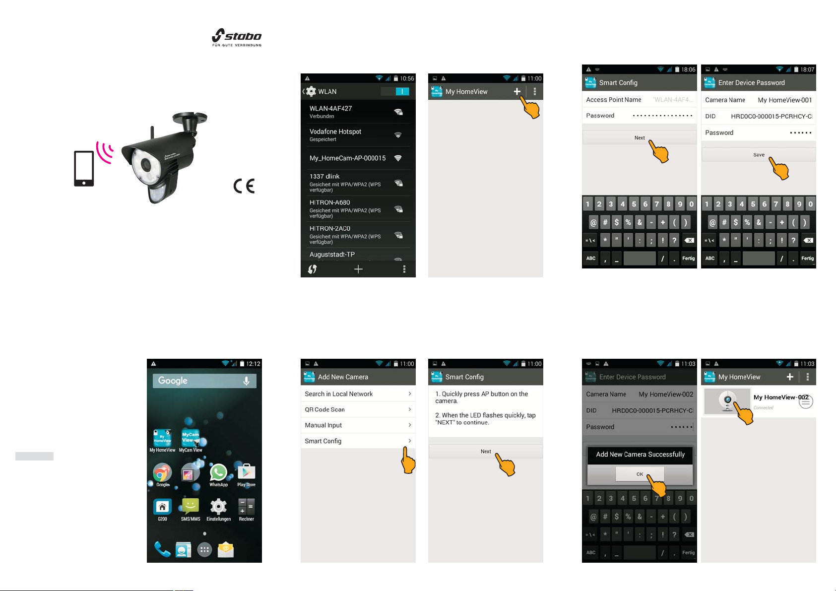
Kamera mit dem Mobilgerät verbinden
1. Stellen Sie sicher, dass Ihr Mobilgerät mit Ihrem WLAN-Router
verbunden ist!
2. Öffnen Sie MyHomeView und tippen Sie auf das Pluszeichen.
5. Geben Sie nun unter Password den WPA-Verschlüsselungscodes
Ihres WLAN-Routers ein. Tippen Sie dann auf Next.
6. Geben Sie nun das Passwort 000000 ein und tippen auf Save.
Lesen Sie vor Inbetriebnahme des Geräts alle Bedienhinweise aufmerksam und
vollständig durch. Eine ausführliche Bedienungsanleitung finden Sie unter
http://stabo.de/fileadmin/BdA/BdA_stabo_multifon_WLAN_outdoor_cam_
Lieferumfang
Farbkamera mit integriertem WLAN-Modul und PIR-Sensor
Netzteil für Kamera (9 V DC/0,6 A)
Kurz-Bedienungsanleitung (deutsch/englisch)
Montagematerial
Bitte überprüfen Sie den Packungsinhalt auf Vollständigkeit.
Prüfen Sie vor der Benutzung der Geräte, ob äußerliche Beschädigungen vorliegen.
In diesem Fall nehmen Sie das Produkt nicht in Betrieb, sondern setzen sich
umgehend mit Ihrem Fachhändler in Verbindung
Wichtig
M8GB_L_DE_EN.pdf
Inbetriebnahme und
Installation
Laden Sie zunächst entsprechend
dem Betriebssystem Ihres Mobilgeräts die iOS- bzw. Android-Version
der App MyHomeView aus dem App
Store bzw. Google Play Store. Geben Sie dazu MyHomeView in die
Suchleiste ein, markieren die App,
laden sie herunter und installieren sie.
Hinweis:
Hinweis: In dieser Bedienungsan-
leitung werden alle Bedienschritte
am Beispiel der Android-Version der
App beschrieben.
Stecken Sie das Netzteil in eine
230 V-Steckdose und verbinden Sie
den Stecker mit der DC IN-Buchse
der Kamera.
3. Tippen Sie nun auf Smart Config.
4. Prüfen Sie, ob die grüne Betriebs-LED der Kamera schnell blinkt:
wenn nicht, drücken Sie die RESET-Taste auf der Kamera-Rückseite.
Tippen Sie anschließend auf NEXT.
7. Es erscheint die Meldung Add New Camera Successfully (Kamera
erfolgreich hinzugefügt). Bestätigen Sie mit OK.
8. Tippen Sie nun auf das Kamera-Symbol.

9. Sie werden nun aufgefordert, das voreingestellte Passwort
(000000) zu ändern: geben Sie ein beliebiges neues Passwort ein.
Hinweis: Das neue Passwort muss aus 8 bis 16 Zeichen (Buch-
Hinweis:
staben und Zahlen) bestehen.
10. Geben Sie das neue Passwort 2x ein und tippen dann auf Save.
Icons
Schnappschuss-Auslöser
Foto-Funktion für Schnappschüsse des Live-Bilds. Das Foto wird
automatisch gespeichert.
Foto-Anzeige
Aufrufen und Anzeigen des/der Fotos.
Intercom-Funktion
Aktivieren/Deaktivieren der Intercom-Funktion (Sprechverbindung
zwischen Kamera und Mobilgerät).
Bildauflösung
Einstellung der Bildauflösung (high: 720P, low: VGA).
Manuelle Aufzeichnung
Starten/ Beenden einer Videoaufnahme des Live-Bildes.
Während der Aufnahme blinkt der rote Punkt.
LED-Strahler
Ein-/Ausschalten des LED-Strahlers. Bei eingeschaltetem Licht
ist der Icon gelb.
Menü
Öffnen des Menüs für individuelle Einstellungen.
Befestigen Sie dann die Kamera.
Stecken Sie das Netzteil in eine 230 V-Steckdose und verbinden Sie
den Stecker mit der DC IN-Buchse der Kamera.
Technische Daten
Kamera
WiFi-Frequenz 2,412 - 2,462 GHz (Channel 1-11)
WiFi-Sicherheit WPA/PSK
WiFi-Standard IEEE 802.11b/g/n
Bildauflösung 720P (1280x720) VGA (640x480)
Bildsensor OV9712 CMOS Sensor
Betriebsspannung 9 V DC / 0,6 A
Weißabgleich automatisch
Arbeits-Temperaturbereich - 20° C ~ 60° C
Schutzklasse IP 54
11. Es erscheint die Meldung Modify Camera Info Successfully
(Kamera-Information erfolgreich geändert). Bestätigen Sie mit OK.
12. Nun erscheint das Live-Bild der Kamera.
Montage und Anschluss der Kamera
Wichtige Hinweise
Bedenken Sie bei der Wahl des Montage-Ortes für die Kamera folgende
Punkte:
Reichweite: Prüfen Sie, ob am geplanten Montage-Ort eine stabile
Verbindung zwischen Kamera und Ihrem WLAN-Router besteht.
Erfassungsbereich: Winkel (ca. 60°) und Reichweite (ca. 5 m) des
Bewegungsmelders.
Beleuchtungssituation: Die Kamera sollte nicht direkt auf starke
Lichtquellen/starkes Sonnenlicht ausgerichtet werden, da dadurch die
Aufnahme überbelichtet wird.
Stromversorgung: Das Netzteil der Kamera darf nicht den Witterungseinflüssen im Freien ausgesetzt werden! Die Steckverbindung des Netzteilkabels muss geschützt werden, damit keine Nässe in die Verbindung
gelangen kann.
Befestigung: Die Schutzart IP 54 ermöglicht eine Anbringung im Freien,
die Kamera sollte dennoch an möglichst geschützter Stelle installiert
werden. Achten Sie auf einen stabilen Montage-Untergrund, der starke
Vibrationen und/oder Stürze ausschließt.
Installieren Sie die Kamera zunächst provisorisch und prüfen Sie, ob
der gewünschte Überwachungsbereich vollständig erfasst wird, bevor
Sie Löcher für die Kamerahalterung bohren! Vergewissern Sie sich,
dass an der Stelle keine Kabel/Leitungen in der Wand liegen, die beim
Bohren beschädigt werden könnten!
Markieren Sie die gewünschte Position der drei Schraublöcher, indem
Sie die Kamerahalterung als Schablone nutzen.
Bohren Sie die drei Montagelöcher und befestigen Sie die Halterung
mit für den Untergrund geeigneten Schrauben.
Maße (B x H x T) 80 mm x 113 mm x 201 mm
Gewicht 365 g ohne Halterung
Bedienungsanleitung
User Manual
stabo WLAN outdoor cam
M8GB-L
Irrtümer und Änderungen vorbehalten. Abbildungen: Abweichungen möglich.
Copyright © 02/2016 stabo Elektronik GmbH
stabo Elektronik GmbH
Münchewiese 14-16 . 31137 Hildesheim/ Germany
Tel. +49 (0) 5121-76 20-0 . Fax: +49 (0) 5121- 51 29 79
Internet: www.stabo.de . E-Mail: info@stabo.de

digital radio technology 2.4 GHz
multifon WLAN outdoor cam M8GB-L
video security system with intercom
Art. no. 51088
Quick start operating instructions
Connecting the camera to the mobile device
1. Make sure that your mobile device is connected to your local network
(WLAN router)!
2. Open the app MyHomeView and tap on the plus sign.
5. Enter the WPA encryption key of your WLAN router under
Password. Then tap on Next.
6. Now enter the passwort 000000 and tap on Save.
Prior to using the device for the first time, carefully and completely read through
all operating instructions. A detailed user manual is ready for download here:
http://stabo.de/fileadmin/BdA/BdA_stabo_multifon_WLAN_outdoor_cam_
Scope of delivery
Color camera with integrated WLAN module and PIR sensor
Power supply unit for camera (9 V DC/0.6 A)
Quick start Operating instructions (German/English)
Mounting material
Please check the contents of the package for completeness.
Prior to using the sets examine them with respect to any external damage. In
case of an external damage, do not put the product into operation, but contact
your specialist dealer immediately.
Important
M8GB_L_DE_EN.pdf
Commissioning and
installation
First download the iOS or Android
version of the app MyHomeView
from the App Store or Google Play
Store according to the operating
system of your mobile device. To do
so, enter MyHomeView into the
search bar, mark the app, download
and install it.
Note:
Note: In these operating instructions,
all operational steps are described
for the Android version of the app.
Plug the power supply unit into a
socket (230 V) and connect the plug
to the DC IN socket of the camera.
3. Now, tap on Smart Config.
4. Check if the green status LED on the camera is flashing: if not press
the RESET key on the back of the camera. Tap on NEXT.
7. Add New Camera Successfully is shown on the display. Confirm
by pressing OK.
8. Now tap on the camera icon.

9. You are now requested to modify the preset password (000000):
enter an arbitrary new password now.
Note: The new password must be composed of 8 characters
Note:
(numbers and letters).
10. Enter the new password twice and then tap on Save.
Icons
Snapshot trigger
Photo function for snapshots of the live image, the photo is
automatically stored.
Photo display
For viewing the photo(s)
Intercom function
Activating/deactivating the intercom function (voice communication
between camera and mobile device).
Image resolution
For setting the image resolution (high: 720P, low: VGA).
Recording trigger
Starting/stopping manually the video recording of the live image.
The red dot is blinking during recording.
LED spotlight
Switching the LED spotlight on/off. The icon is yellow if the light
is on.
Menu
Opening the menu for individual settings.
Afterwards mount the camera.
Plug the power supply unit into a socket (230 V) and connect the plug
to the DC IN socket of the camera.
Technical Data
Camera
WiFi frequency 2.412 - 2.462 GHz (channel 1-11)
WiFi security WPA/PSK
WiFi standard IEEE 802.11b/g/n
Image resolution 720P (1280x720) VGA (640x480)
Image sensor OV9712 CMOS Sensor
Operating voltage 9 V DC / 0.6 A
White balance automatic
Working temperature range - 20° C ~ 60° C
Protection class IP 54
11. Modify Camera Info Successfully is shown on the display.
Confirm by pressing OK.
12. Now the live image appears.
Mounting and connecting the camera
Important information
Consider the following when selecting the mounting position of the
camera:
Range: Check whether the connection between the camera and your
WLAN router is stable at the intended mounting position.
Area of coverage: Angle (approx. 60°) and range (approx. 5 m) of the
motion detector.
Lighting conditions: The camera should not be orientated towards
direct, strong light sources/sunlight, since overexposed images may
result.
Power supply: The camera's power supply unit must not be exposed
to the weather in the open! The plug-in connection of the power supply
cable must be protected for preventing any moisture from entering.
Mounting: Protection type IP 54 allows devices to be installed in the
open. However, the camera should nevertheless be installed in a well
protected place. Make sure that the base material for mounting is stable
and does not give rise to strong vibrations and/or falls.
First, install the camera only provisionally and check whether the desired
monitored area is completely covered prior to drilling the holes for the
camera support! Make sure that no cables or conducts are placed in
the wall which may be damaged when drilling!
Mark the desired position for the three drilling holes of the fixing screws
by using the camera support as drilling jig.
Drill the three mounting holes and fix the support using screws which
are suitable for the respective base material.
Dimensions (H x W x D) 80 mm x 113 mm x 201 mm
Weight 350 g without support
Bedienungsanleitung
User Manual
stabo WLAN outdoor cam
M8GB-L
Errors and technical modification reserved, pictures may vary.
Copyright © 02/2016 stabo Elektronik GmbH
Münchewiese 14-16 . 31137 Hildesheim/ Germany
Tel. +49 (0) 5121-76 20 - 0 . Fax: +49 (0) 5121- 51 29 79
Internet: www.stabo.de . E-Mail: info@stabo.de
stabo Elektronik GmbH
 Loading...