

Page 1
Operating manual
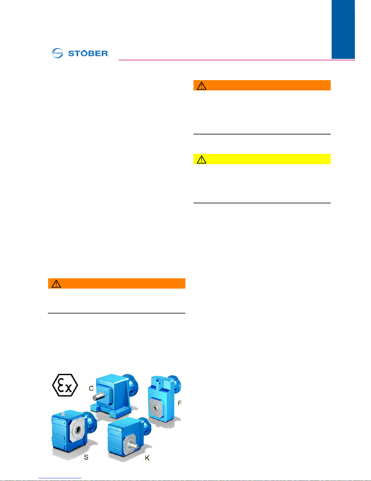
Explosion-protected gear units C/F/K/S
101/2019
WE KEEP THINGS MOVING
ID 443028_en.01
en
www.stober.com
These operating instructions contain information about the
transport, assembly, commissioning and service of gear units
from STOBER. Observe the applicable documents of attached motors and additional drive components.
1 Operation in accordance with its in-
tended use
Explosion-protected gear units from STOBER meet the requirements of the ATEX Directive 2014/34/EU and comply
with the following standards:
• EN 1127-1:2011-07
• EN ISO 80079-36:2016-04
• EN ISO 80079-37:2016-04
The gear units are intended for installation in commercial machines and systems. Intended use includes:
• Use of the gear unit exclusively for the application that it
was designed for.
• No modifications to the gear unit by the customer.
• Use of the gear unit only in the zone subject to explosion
hazard that corresponds to the identification on the ATEX
nameplate.
• Use of the gear unit in the surrounding temperature range
Ta that is specified on the ATEX nameplate.
• The maximum thickness of the dust deposit on the gear
unit may not be more than 5 mm according to EN 502812-1.
• No overload of the gear unit with regard to the maximum
permitted speeds and torques that are specified in the order confirmation.
• Compliance with the inspection and maintenance intervals.
• Observe these operation instructions.
WARNING!
Unintended use of the gear unit can lead to explosions
that can cause serious injuries or even death.
Only use the gear unit as intended!
2 Safety information
WARNING!
Failure to comply with these operating instructions can
cause ignition sources when using the gear unit in areas
subject to explosion hazard and lead to explosions that
can cause serious injuries or even death.
Comply with the instructions in these operating instruc-
tions!
Also follow the applicable national, local and system-specific
requirements.
CAUTION!
Burns!
The surface temperature of the gear unit can significantly exceed 65° C in operation!
Allow the gear unit to cool down sufficiently before touch-
ing it or wear protective gloves.
2.1 Ignition hazard and protective measures
The following is an overview of ignition hazards that can arise
when operating the gear unit and protective measures that
are described in these operating instructions.
Ignition hazard: hot surfaces
Possible causes: increased friction due to improper assembly, wear, overload or leaks.
Protective measures:
• Compliance with the maximum permitted torques and
speeds
• Limitation of the motor current
• Control before commissioning
• Measurement of the maximum surface temperature
during commissioning
• Regular inspection and maintenance
Ignition hazard: mechanically generated sparks
Possible causes: improper assembly of leaks
• Control before commissioning
• Regular inspection and maintenance
Ignition hazard: electrostatic discharge
Possible causes: friction processes, potential differences between components
• Exclusive use of components with ATEX approval
• Earth the gear unit housing
2.2 Personnel requirements
All work on the electrical equipment of the drive units must be
performed by qualified electricians. Installation, maintenance
and repairs of mechanical parts must be performed by fitters,
industrial mechanics or persons with comparable qualifications.
Page 2
Operating manual
Explosion-protected gear units C/F/K/S
2
ID 443028_en.01
WE KEEP THINGS MOVING
01/2019
en
www.stober.com
3 Description of the gear unit
The technical data of the gear unit/geared motor can be found
in the order confirmation. This refers to the lubricant used that
is specified on the nameplate of the gear unit. Other technical
data as well as dimensional drawings can be found in the appropriate catalog from STOBER.
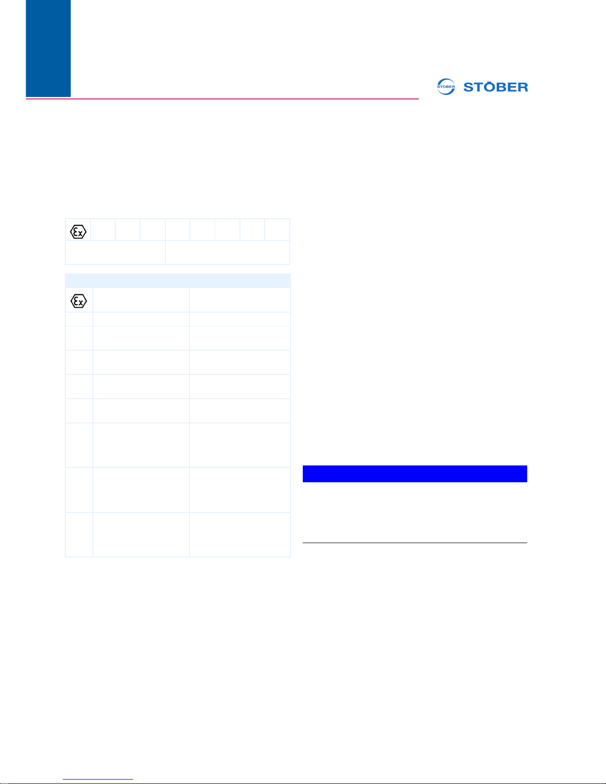
3.1 ATEX identification
The gear unit is identified on the ATEX nameplate as follows.
1) According to IEC 60079-10-X
4 Transportation and storage
When transporting the gear units/geared motors make certain
not to damage the shafts and bearings with impacts.
For transport of the gear units/geared motors C6-C10 and K5
- K10 use the eyebolts on the gear unit housing. Lift the other
gear units/geared motors directly on the gear unit housing using a suitable lifting cable.
Eyebolts are provided only for lifting the gear units/geared
motors without additional attachments. When you remove the
eyebolts after installation, the threaded holes must be permanently closed corresponding to the protection type of the gear
units/geared motors.
The gear units/geared motors may only be stored in enclosed, dry rooms. Storage in open air areas with a roof is only
permitted for brief periods. Protect the gear units/geared motors from all damaging environmental effects and mechanical
damage.
Avoid extreme temperature fluctuations with high relative humidity when the gear units/geared motors are being stored
temporarily to prevent formation of water from condensation.
Long-term storage
If long-term storage is planned, protect the bare parts of the
gear unit against corrosion. Completely fill the gear unit with
lubricant that is specified on the nameplate. Reduce the lubricant to the correct filling quantity according to the nameplate
before commissioning the drive.
5 Mounting
Inspect the delivery for any transport damage immediately after you receive it. Notify the transport company of any damage immediately. Do not operate damaged gear units/geared
motors.
Remove the packaging of the gear unit/geared motor and dispose of it according to the applicable legal requirements on
site.
Check the following before installing the gear unit:
• Do the specifications on the ATEX nameplate of the gear
unit (gear group, category, EPL, temperature class and
maximum surface temperature) correspond with the
zone subject to explosion hazard where the gear unit is
to be used?
• Is the gear unit installed in a zone that is not subject to explosion hazard?
• Do all drive and output elements to be mounted have appropriate explosion protection?
NOTICE
The lip seals of the shaft seal rings can be damaged by
the use of solvents.
When removing the corrosion protection, make sure that
the lip seals of the shaft seal rings do not come into contact with solvents.
Completely remove all corrosion protection on the shaft ends
prior to installation.
5.1 Installation positions
The version of the gear unit and the lubricant amount filled at
the factory is matched to the installation position of the gear
unit. The gear unit may therefore only be installed at the installation position specified in the order confirmation. A sign
on the gear units shows which gear unit side must point downwards.
II 2 G Ex h IIC T3 Gb
Identification according to
ATEX Directive
Identification according to
EN ISO 80079-36
Code Designation Explanation
Ex-symbol According to ATEX
Directive
II Device group
2
3
Device category
G
D
Type of explosive
atmosphere
Gas
Dust
Ex Ex-symbol According to EN ISO
80079-36
h Code letter for non-
electrical devices
IIC
IIIC
Explosion group Gases (such as hydrogen)
Combustible suspended
particles non-conductive
and conductive dusts
T3
T4
T200°
T120°
Temperature class For gases (max. 200°C)
For gases (max. 135°C)
For dusts (max. 200°C)
For dusts (max. 120°C)
Gb
Gc
Db
Dc
Equipment Protection
Level (EPL)
For zone 1
1
For zone 2
1
For zone 21
1
For zone 22
1
Page 3

Operating manual
Explosion-protected gear units C/F/K/S
301/2019
WE KEEP THINGS MOVING
ID 443028_en.01
en
www.stober.com
5.2 Installation of gear unit
Mount the gear unit on an even, vibration-reducing and torsion resistant substructure. Use screws of strength class 10.9
to fasten the gear unit via the pitch circle diameter. Use
screws of strength class 8.8 for all other fastening types.
Observe the following for assembly:
• The housing feet and attachment area may not be braced
against each other.
• The permitted shear and axial forces may not be exceeded.
• Screws for filling and draining the lubricant as well as
available ventilation valves must be freely accessible.
• Earthing the gear unit housing via metal components of
the system must be ensured.
Gear units/geared motor with solid shaft; installation of
power transmission elements:
The output shaft is equipped with a centering thread according to DIN 332, Sheet 2, which is provided both for fitting and
for axial mounting of transmission elements (gear, chain
wheel, pulley, coupling hub) by means of a central screw.
Shaft ends with a diameter up to 55 have tolerance ISO k6,
those larger than 55 have tolerance ISO m6. The fitting keys
correspond to DIN 6885, Sheet 1.
NOTICE
Damage to the bearing race.
Avoid all impacts to the output shafts.
Gear units/geared motor with hollow shaft and fitting key
connection:
a) Shaft-mounted gear units are mounted on the drive shaft of
the machine to be driven. The reactive torque must be supported either by flange-mounting of the gear unit or a torque
bracket. If flange-mounted, the flange connection point on the
machine must not exceed a right-angle deviation to the shaft
axis of 0,03/100 mm (danger of distortion of bearings, excessive bending strain on the machine shaft).For gear units with
a hollow shaft, always make sure that the machine shaft is
aligned with the hollow shaft of the gear unit (max. deviation
≤ 0.03 mm).b) The hollow shaft bore is designed according to
tolerance ISO H7 and the keyway according to DIN 6885
Sheet 1. The machine shaft must be ISO k6! The machine
shaft must have a centering thread according to DIN 332,
Sheet 2. The integrated fitting/push-off disk is provided for axial mounting of the gear unit by means of a central screw.
Fitting the gear unit onto the machine shaft:
- Coat machine shaft with mounting grease
- Coat hollow shaft spiral groove and keyway with mounting
grease
- Fit gear unit by means of central screw. Do not use ham-
mer!
NOTICE
Rust on of the gear unit.
Never mount the gear unit without lubrication, since it will
rust on and cannot be removed for repairs.
Disassembly: Press the gear unit off by means of the pushoff disk and matching push-off screw. Support machine shaft
to keep it centered! If the shaft is stuck, we recommend applying rust penetrating oil to the shaft ends in the key seat for an
extended period.
Gear units/geared motor with hollow shaft and shrink
disk:
The information under a) applies here as well and must be observed! The description of the shrink disk connection and the
installation and safety instructions can be found in the TECHNICAL INFORMATION SHEET “Installation instructions for
hollow shaft with shrink disk”.
5.3 Ventilation
Gear units of sizes C0 - C5, F1 - F6 and K1 - K4 are closed
on all sides and are not vented. In contrast, gear units of sizes
C6 - C10, K5 - K10, S0 - S4 are vented as standard, whereby
the position of the vent valve depends on the installation position.
The vent valves are sealed with a transport lock to prevent lubricant escaping. Remove the transport lock after assembling
the gear unit.
6 Commissioning
6.1 Prior to commissioning
Check the following before commissioning:
• Is it ensured that the gear unit is adequately vented and
no external heat input (e.g. Via a coupling) is present?
The cooling air may not exceed a temperature of 40° C.
• Is the transport lock of the vent valves removed?
• For gear units with hollow shaft and shrink disk: were the
clamping bolts tightened to the specified torque? Is the
cover of the shrink disk properly mounted?
• Does the attached motor cover the full flange surface of
the motor adapter for gear units with motor adapters so
that IP65 protection class is provided?
• For gear units with motor adapter ME: is the clamp coupling tightened to the specified torque? Is the plug properly mounted?
• If ring screws were dismantled, are the holes sealed with
appropriate plugs?
• Is it ensured that no gear unit overload relating to the permitted torque can occur due to the mounted motor? (The
permitted torque can be found in the order confirmation.)
• When operating the attached motor at a drive controller:
is the drive controller parameterized so that a gear unit
overload is prevented?
Page 4

Operating manual
Explosion-protected gear units C/F/K/S
4
ID 443028_en.01
WE KEEP THINGS MOVING
01/2019
en
www.stober.com
WARNING!
Risk of injury due to moving parts!
Before switching on the drive, check the following:
Are no persons in danger due to start-up?
Is all protection and safety equipment properly installed,
in test operation too?
Is the drive not blocked?
Are the brakes released?
Is the direction of rotation of the drive correct?
Are components attached to the output such as feather
keys or coupling elements adequately secured against
centrifugal forces?
6.2 During commissioning
As the operating conditions for gear units are very different, it
must be ensured for safe operation under maximum operating conditions that the surface temperature of the gear unit
does not exceed the maximum permitted value. For this purpose, take the following measurement with a standard commercial temperature measurement device.
Determine the surface temperature at the gear unit/motor
transition where the terminal box position prevents ventilation
by the motor fan.
For gear units with a motor adapter or free drive shaft, determine the surface temperature at the joining seam between
the gear unit flange on the input side and the attachments.
The maximum surface temperature is reached after approx. 3
hours under full load and may not exceed the maximum value
of 90° C for the highest surrounding temperature. Stop the
drive immediately if the maximum value is exceeded and contact STOBER Service.
7 Service
7.1 Inspection and maintenance
To ensure safe operation with regard to explosion protection,
carry out the following inspections and maintenance work at
the specified intervals:
Daily or according to dust accumulation
• Remove dust deposits from the gear unit surface (STOBER recommends removing dust deposits with a thickness
of 1 mm or more)
• If present, check rubber buffer of the torque arm and replace if wear or damage is detected
Every 500 operating hours, every 3 months at the latest
• Visually check the shaft seal rings for leaks
• Check operating noise for possible bearing damage
Every 5000 operating hours, every 5 years at the latest
• Replace lubricant
• Replace shaft seal rings
Every 10000 operating hours
• Replace rolling bearing
Comply with the lubricant specification and amount that is
stated on the nameplate of the gear unit when changing the
lubricant. Do not mix lubricants with different specifications.
7.2 In the event of disruptions
Changes compared to normal operation indicate that the
function of the drive has been impaired. This includes:
• Higher power consumption, temperatures or vibrations
• Unusual noises or odors
• Leaks on the gear unit
• Monitoring devices responding
In this case, stop the drive as quickly as possible and contact
STOBER Service.
7.3 Contact
STOBER Service will be happy to help you:
• If you have queries about the product
• In the event of a fault
• Carrying out maintenance work
• If you need spare parts.
Have the serial number and the type designation of the gear
unit ready when you contact us. This can be found on the
nameplate of the gear unit.
For spare part orders, you will also need the item number of
the spare part in the relevant spare parts list.
Contact data Parent company Germany:
STÖBER ANTRIEBSTECHNIK GmbH & Co. KG
Kieselbronner Str. 12
75177 Pforzheim
Service Hotline +49 7231 582-3000
[email protected]
Contact data Subsidiary USA:
STOBER Drives Inc.
1781 Downing Drive
Maysville KY 41056
Service Hotline +1 606 563-6035
[email protected]
7.4 Disposal
This product contains recyclable materials. Observe local applicable regulations for disposal.
 Loading...