

Page 1
Page 2

Page 3

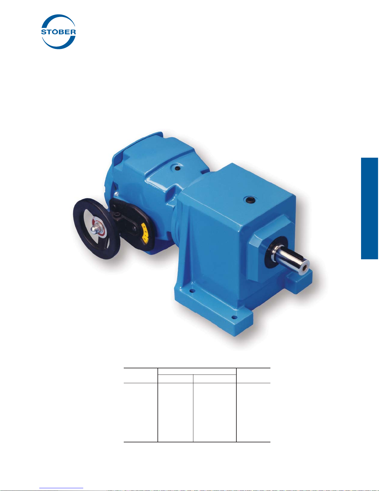
ComTrac® Adjustable Speed Drives
Company Profi le
STÖBER was fi rst established in Germany in 1934, and has been
a pioneer in the gearing industry ever since. Through constant
innovation, STÖBER today is known for high precision, high effi ciency and low noise in their various gearing technologies. STO-
®
Drives Inc., located in Maysville, KY, manufactures products
BER
to serve the North American market.
Beginning with the ComTrac
ers, STÖBER established itself as a technology leader, later
adding the innovative MGS
offering. MGS
est of washdown environments.
STÖBER next introduced ServoFit
heads, establishing the standard for low noise and low backlash in the servo industry. The recent introduction of the SMS
ServoFit Modular System gearheads adds a high precision, cost
effective alternative to the servo market.
STÖBER has the broadest offering of speed reducers available,
providing one stop shopping for both the industrial market and the
rapidly growing motion control market.
On behalf of the worldwide family of STÖBER employees, we
thank you for trying our products and pledge to continue to meet
your product and service needs with the newest solutions.
Sincerely,
®
Food and Beverage Reducers excel in the harsh-
®
Mechanical Variable Speed Reduc-
®
Modular Gear System to the product
®
Precision Planetary Gear-
®
Table of Contents
ComTrac Adjustable Speed Drives
Advantages and Features ...................................................2
Performance ........................................................................3
Washdown Duty ..................................................................4
Operating Characteristics ....................................................5
Ratings and Dimension
.50 HP .......................................................................6
.75 HP .......................................................................7
1.0 HP .......................................................................8
1.5 HP .......................................................................9
2.0 HP .....................................................................10
3.0 HP .....................................................................11
5.0 HP .....................................................................12
Electric Remote Control (ERC) .........................................13
Selection and Performance Characteristics ......................14
Installation Instructions ......................................................16
Maintenance and Lubrication ............................................18
"C" Series MGS Adjustable Speed Drives
Performance Specifi cations ...............................................19
Ratings ..............................................................................20
Dimensions ........................................................................34
Mounting Positions ............................................................70
Bernd Stöber, Chairman
Stöber Antriebstechnik GmbH
Peter Feil, VP/General Manager
STOBER Drives, Inc.
"F" Series MGS Adjustable Speed Drives
Performance Specifi cations ...............................................37
Ratings ..............................................................................38
Dimension .........................................................................44
Mounting Positions ............................................................70
"K" Series MGS Adjustable Speed Drives
Performance Specifi cations ...............................................47
Ratings ..............................................................................48
Dimensions ........................................................................64
Mounting Positions ............................................................71
Mounting Hollow Output Units ...........................................68
Mounting Positions ............................................................69
Terms and Conditions ........................................................72
STOBER Drives Inc. • ComTrac2012 • www.stober.com 1
Page 4

ComTrac® Adjustable Speed Drives
Advantages:
You're probably already aware of the many common-sense
advantages offered by traction-type adjustable speed drives like
the ComTrac drive. When compared to mechanical belt-type, or
electrical adjustable speed drives, traction type drives offer:
• Often, a lower initial cost.
• Few worries about motor overheating during low speed
operation.
• No motor brushes to replace.
• Very compact and lightweight when compared to other mechanical drives.
• Simple design with few rotating components to wear or replace.
• Easily serviced by semiskilled personnel
• Low maintenance – doesn't need to be cycled through its
speed range to prevent component damage.
• 2 year warranty–your assurance of satisfactory product performance.
Features:
Drive cone – The drive cone is made from ductile iron and is
precision ground for long service life. It contains inner air chambers for effi cient heat dissipation. It is independently supported by
a shielded bearing mounted into the motor adapter/slide – not just
by the motor bearing.
Traction ring – ComTrac's self-lubrication traction ring is made
from a proprietary material that provides exceptional resistance
to wear and high temperatures. When replacement is necessary,
only the ring and not the entire friction ring mounting fl ange is
replaced.
Speed adjustment – ComTrac's rack and pinion speed adjustment system features stainless steel components to resist corrosion and is dust resistant by design. The stainless steel pinion
shaft and ductile iron rack are designed to provide assured speed
adjustments in the wettest, dirtiest environments.
Handwheel control – Handwheel control with a position indicator
is standard on every ComTrac drive. Remote speed controls and
overspeed protection is also available.
All ComTrac drives are shipped with the handwheel positioned
on the left as viewed from the output shaft end of the drive. The
handwheel can be quickly and easily moved to the right side by
using the tools and instructions included with the drive.
Mounting position – ComTrac drives can be mounted in virtually
any position.
NEMA C-face input – All ComTrac drives feature a NEMA Cface input – that means standard off-the-shelf motors, available
locally. ComTrac's patented corrosion resistant collet clamp ring
makes motor shaft attachment fast and simple. The proper hex
wrenches are included with each unit in the motor access cover.
When the motor must be replaced, it can be done easily and
quickly without disassembly of the entire drive.
In addition, the 0F unit is standard with a NEMA C-face output
fl ange. It enables you to add adjustable speed capability to new or
existing applications.
Torque compensator – The torque compensator assembly features high-capacity cylindrical roller bearings – not needle bearings – for long life and quiet operation. The design allows speed
changes during operation or while the drive is at rest. The load
compensating cams precisely match the pressure between the
drive cone and the traction ring in proportion to the load torque.
Cast iron housing – High tensile strength cast iron housing for
long service life in demanding applications.
Stainless steel nameplate.
Two year warranty – Every ComTrac unit is backed by a two-
year warranty.
Delivery – ComTrac units are shipped in 3 days or less.
Selection:
In general, proper selection of a ComTrac drive is as easy as the
drive is to operate.
1. Establish the maximum horsepower required by the driven
machine at maximum speed.
2. Select the drive which meets or exceeds the maximum HP
rating of the driven machine at maximum speed.
Part No. Example:
TD47 0 F K182 W
Traction Drive Model/Size
Input for NEMA Frame Size (
0 – Non-geared
F – Flange Mount
182TC)
Washdown/Severe Duty (Option)
Speed Control Made Simple!
2 STOBER Drives Inc. • ComTrac2012 • www.stober.com
Page 5
ComTrac® Adjustable Speed Drives
Performance Specifi cations:
• Horsepower ratings – from 1/2 to 10
• Output speeds – available from 2180 to 311 RPM
• Speed range – 5:1 to 7:1
• Output torques – up to 496 in.lbs.
• NEMA frames – from 56C to 215TC
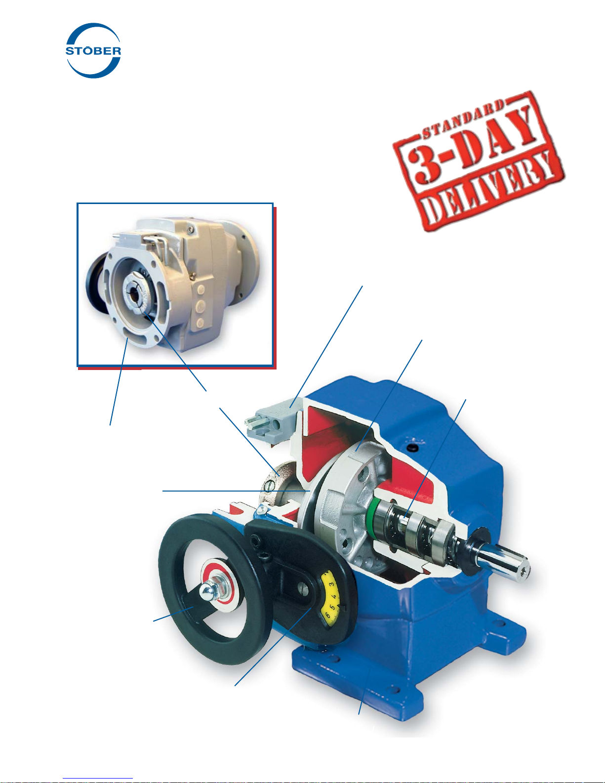
Access Cover with wrenches
NEMA C-face Input
Drive Cone
Handwheel
Collet Clamp Ring
Friction (Traction)
Ring Flange
Assembly
Torque Compensator
Speed Adjustment Dial
STOBER Drives Inc. • ComTrac2012 • www.stober.com 3
Cast Iron Housing
Footed unit shown for illustration only.
This style is no longer available.
Page 6
ComTrac® Adjustable Speed Drives
Washdown/Outdoor Service/ Severe Duty
Advantages:
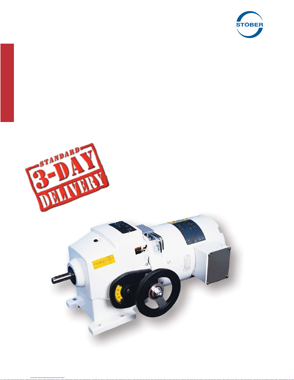
STÖBER has developed a severe duty protection package for
ComTrac drives which signifi cantly improves the drives' ability
to withstand the effects of outdoor use, exposure to excessively
humid or acidic environments, or spray washed with water or
caustic fl uids.
The ComTrac severe duty package includes corrosion protection
for all functional components and housings including:
• Drive cone
• Motor clamping ring
• Motor slide and rack
• Bearing housing
• Main housing cover
To prevent corrosion, these components are protected by a spe-
cial heat treatment process similar to chrome plating.
Features:
Drive cone – Corrosion protected drive cone extends cone and
ring life.
Speed adjustment – The protected motor slide, stainless steel
control shaft with pinion, and greased rack and slideway assure
the proper speed adjustment.
NEMA C-face input – ComTrac's patented corrosion resistant
collet clamp ring assures ease of motor replacement.
External surface – All external surfaces are protected with a special acid-resistant epoxy paint to prevent corrosion and lubricant
contamination.
Internal surface – All internal surfaces and bearing housing are
protected with a special anticorrosion paint.
Double seals – Double output seals can be provided for maximum protection in very harsh environments.
Mounting position – ComTrac drives in a vertical mounting position (output shaft down) must be adapted to allow water to drain.
Stainless steel nameplate – Other features of the severe duty
unit are: stainless steel nameplate, rivets, and chrome plated
bolts.
Two year warranty – Like the standard drive, this ComTrac unit
is also backed by a two-year warranty.
Delivery – ComTrac units are shipped in 3 days or less.
4 STOBER Drives Inc. • ComTrac2012 • www.stober.com
Footed unit shown for illustration only.
This style is no longer available.
Page 7
ComTrac® Adjustable Speed Drives
Operating Characteristics
Operation:
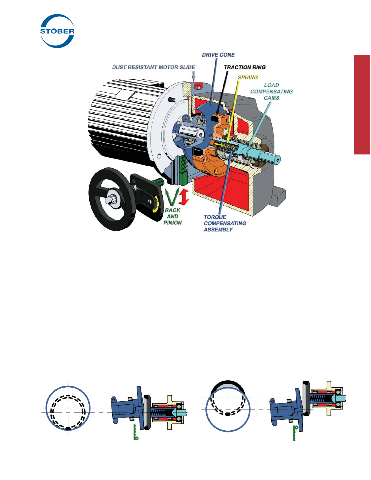
The ComTrac drive is an adjustable speed traction drive. Its
operation is based upon the transfer of power between the motor
mounted drive cone and the traction ring. The drive cone and
the traction ring are forced together to transmit torque through
the use of a spring loaded torque compensator assembly.
At rest, the spring inside the torque compensator produces only
a small contact pressure between the drive cone and traction
ring. Unlike other mechanical drives, the minimal spring pressure
allows speed changes to be made while the drive is at rest.
As the drive is started, the load compensating cams move
against each other to increase pressure between the drive cone
and traction ring. During operation, the load compensating
cams maintain the proper amount of pressure between the drive
cone and traction ring in proportion to the output load torque
required.
Speed Control Made Simple!
• Turn the handwheel – pinion moves the rack on the motor slide – up or down.
Footed unit shown for illustration only.
This style is no longer available.
Speed changes are made by changing the relative running
diameters of the drive cone and the traction ring. As the motor
and drive cone are moved upward, the contact point between the
cone and ring moves to the faster running outer diameter of the
drive cone and output speed increases. As the motor and drive
cone are lowered, the contact point between the cone and ring
moves to the slower running center of the drive cone and output
speed decreases.
Movement of the motor and drive cone are accomplished
through the use of a handwheel attached to a rack and pinion.
By turning the handwheel, the motor is easily raised or lowered
on the dust resistant motor slide. Speed changes can also be
made through the use of an optional electric remote control which
replaces the handwheel.
Contact Point
Maximum speed – motor slide up. Minimum speed – motor slide down.
STOBER Drives Inc. • ComTrac2012 • www.stober.com 5
Contact Point
Page 8
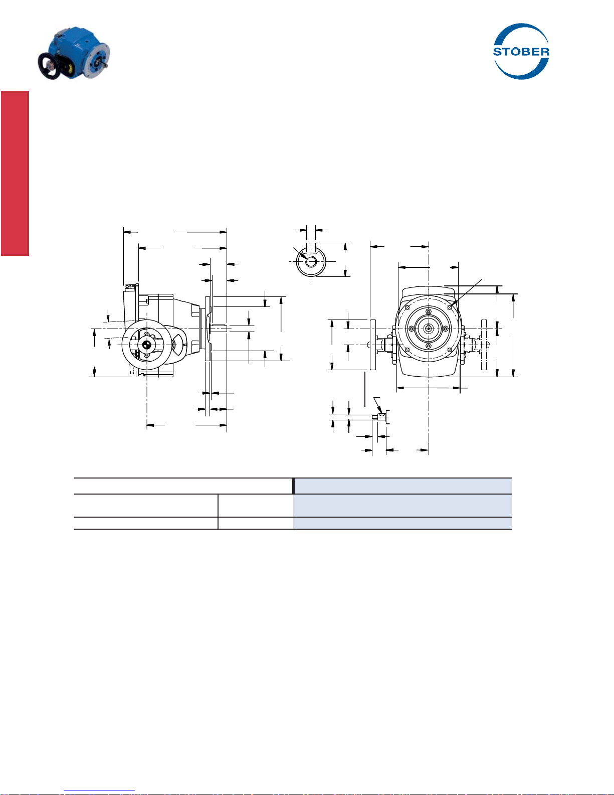
ComTrac® Adjustable Speed Drives
.50 HP @ 1750 RPM
All TD27 units are available with 56C and 143TC input.
Motor Slide
Adjustment
2.09
5.55
Part No. – 33 lbs.
TD270FK56
Flange Style
56C Input and Output
Constant Horsepower Range Constant Torque Range
MAXIMUM TRANSITION
RPM
2,180 12.2 0.42 334 66 0.35 311 66 0.33
10.67
8.86
1.87
1.65
.625
+.0000
-.0005
.12
.47
2.06
8.07
(1)
in.lbs. HP RPM
.1875 +.0000 / -.0005
x 1.38 Lg.
#12-24 NC
.71
4.500
+.000
-.001
6.50
1.57
4.92
M10
.5903
+.0000
-.0005
1.30
Handwheel Shaft Dimensions
(2)
(1)
in.lbs. HP RPM
MINIMUM
5.67
.20 x .26
.51
4.29
5.875
(1)
in.lbs. HP
6.22
3
/8-16 NC
4.41
4.72
8.11
All ratings shown are based on 1750 RPM motor speed and are rated to provide constant torque through the entire speed range. Contact STOBER for
constant horsepower applications.
1)
Speed tolerance at rated load is ±3%. At less than rated load, minimum speed may increase 5%.
2)
The ComTrac drive operates at constant horsepower above transition values and at constant torque below transition values. Note shaded area.
MOTOR MUST BE ORDERED SEPARATELY.
Engineering advances may cause slight changes to the information shown.
6 STOBER Drives Inc. • ComTrac2012 • www.stober.com
Page 9
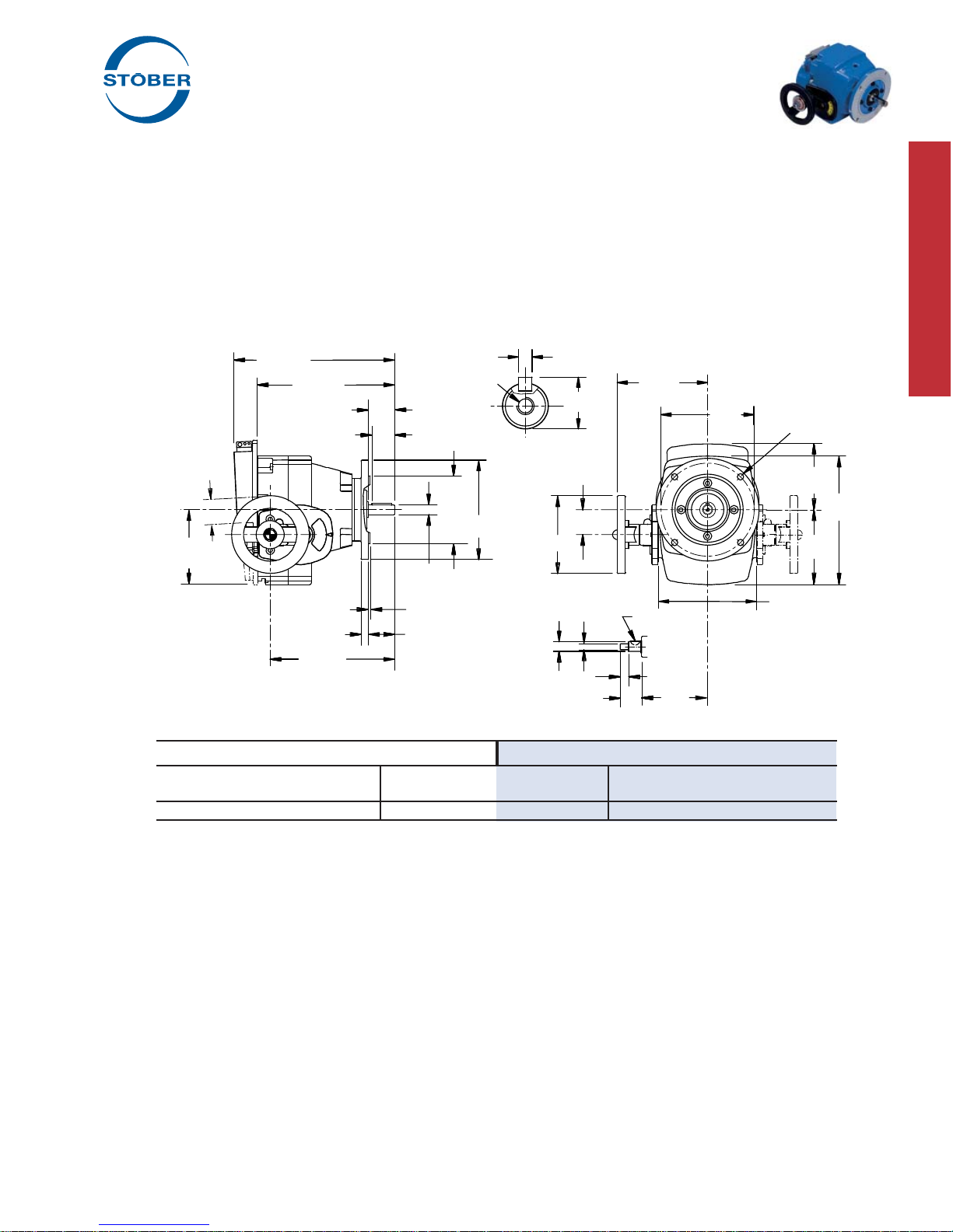
Motor Slide
Adjustment
2.09
5.55
ComTrac® Adjustable Speed Drives
.75 HP @ 1750 RPM
All TD27 units are available with 56C and 143TC input.
+.0000 / -.0005
10.67
8.86
8.07
1.87
.47
1.65
.625
+.0000
-.0005
.12
2.06
#12-24 NC
4.500
+.000
-.001
6.50
.1875
x 1.38 Lg.
5.67
.71
1.57
4.92
.5903
+.0000
-.0005
M10
1.30
.20 x .26
.51
4.29
Handwheel Shaft Dimensions
5.875
3
/8-16 NC
4.41
8.11
4.72
6.22
Part No. – 33 lbs.
TD270FK56
Flange Style
56C Input and Output
Constant Horsepower Range Constant Torque Range
MAXIMUM TRANSITION
RPM
(1)
in.lbs. HP RPM
(1)
in.lbs. HP RPM
2,180 18.3 0.63 582 66 0.61 311 66 0.33
All ratings shown are based on 1750 RPM motor speed and are rated to provide constant torque through the entire speed range. Contact STOBER for
constant horsepower applications.
1)
Speed tolerance at rated load is ±3%. At less than rated load, minimum speed may increase 5%.
2)
The ComTrac drive operates at constant horsepower above transition values and at constant torque below transition values. Note shaded area.
MOTOR MUST BE ORDERED SEPARATELY.
Engineering advances may cause slight changes to the information shown.
STOBER Drives Inc. • ComTrac2012 • www.stober.com 7
(2)
MINIMUM
(1)
in.lbs. HP
Page 10
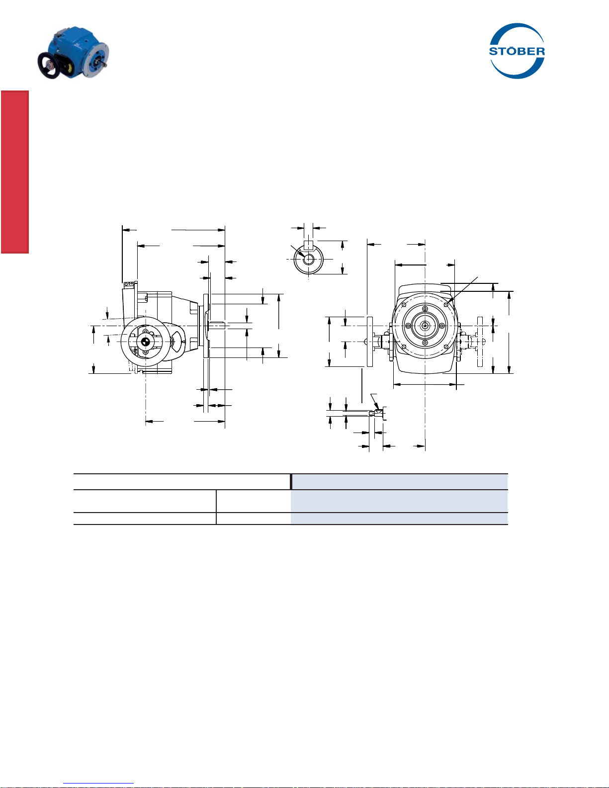
Motor Slide
Adjustment
2.09
5.55
Part No. – 33 lbs.
TD270FK143
Flange Style
143TC Input
56C Output
ComTrac® Adjustable Speed Drives
1.0 HP @ 1750 RPM
All TD27 units are available with 56C and 143TC input.
+.0000 / -.0005
10.67
8.86
8.07
1.87
.47
1.65
+.0000
.12
2.06
#12-24 NC
4.500
+.000
-.001
.625
-.0005
6.50
.1875
x 1.38 Lg.
5.67
.71
1.57
4.92
.5903
+.0000
-.0005
M10
1.30
.20 x .26
.51
4.29
Handwheel Shaft Dimensions
5.875
6.22
3
/8-16 NC
4.41
4.72
8.11
Constant Horsepower Range Constant Torque Range
MAXIMUM TRANSITION
RPM
(1)
in.lbs. HP RPM
(1)
in.lbs. HP RPM
2,180 24.4 0.84 821 66 0.86 311 66 0.33
All ratings shown are based on 1750 RPM motor speed and are rated to provide constant torque through the entire speed range. Contact STOBER for
constant horsepower applications.
1)
Speed tolerance at rated load is ±3%. At less than rated load, minimum speed may increase 5%.
2)
The ComTrac drive operates at constant horsepower above transition values and at constant torque below transition values. Note shaded area.
MOTOR MUST BE ORDERED SEPARATELY.
Engineering advances may cause slight changes to the information shown.
(2)
MINIMUM
(1)
in.lbs. HP
8 STOBER Drives Inc. • ComTrac2012 • www.stober.com
Page 11
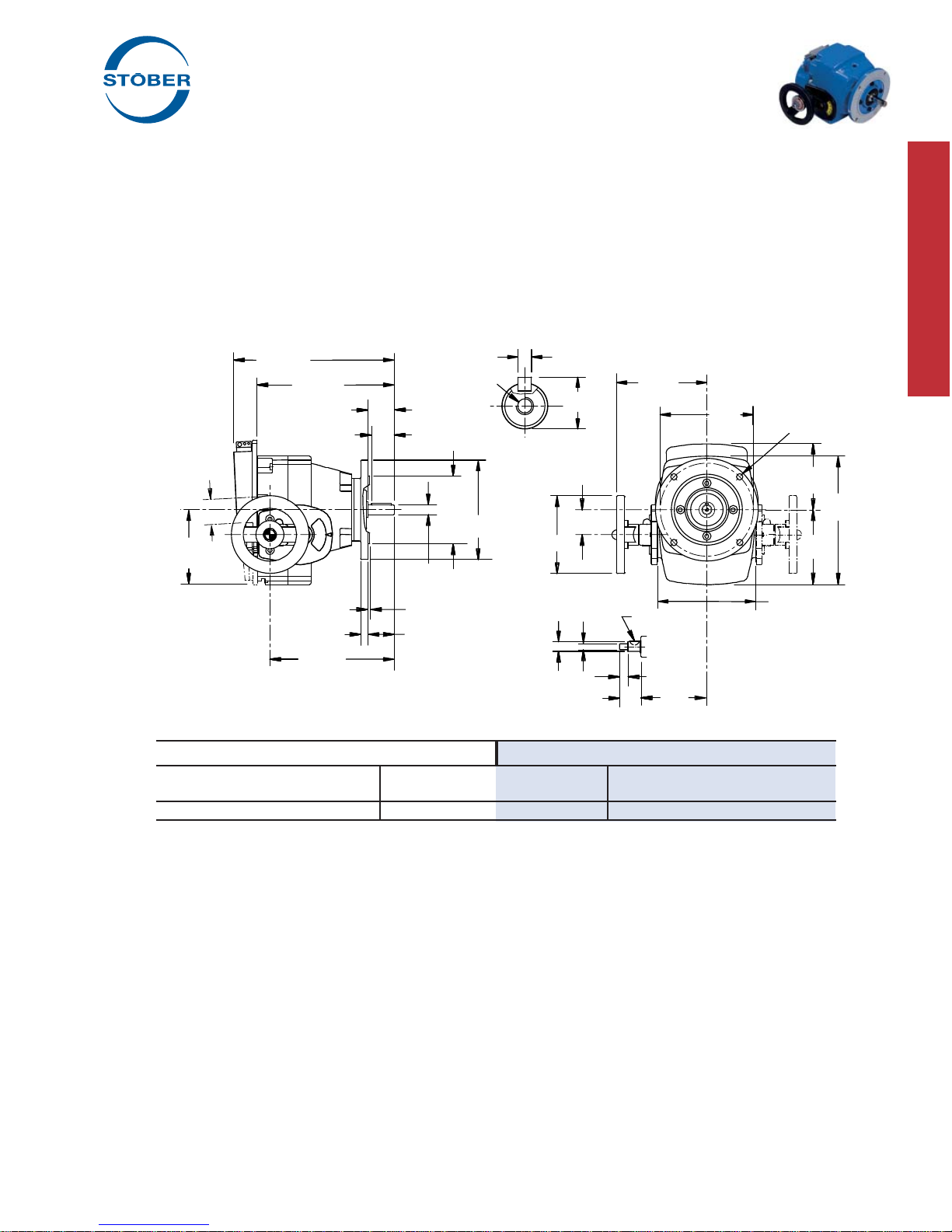
Motor Slide
Adjustment
2.17
5.67
ComTrac® Adjustable Speed Drives
1.5 HP @ 1750 RPM
+.0000 / -.0005
11.69
9.88
9.09
2.24
.47
1.97
.875
+.0000
-.0005
.12
2.13
1
/4-20 NC
4.500
+.000
-.001
6.50
.1875
x 1.77 Lg.
5.91
.96
2.05
4.92
.5903
+.0000
-.0005
M10
1.30
.20 x .26
.51
4.53
Handwheel Shaft Dimensions
5.875
3
/8-16 NC
4.37
9.72
5.94
6.69
Part No. – 51 lbs.
TD370FK145
Flange Style
145TC Input
143TC Output
Constant Horsepower Range Constant Torque Range
MAXIMUM TRANSITION
RPM
(1)
in.lbs. HP RPM
(1)
in.lbs. HP RPM
2,100 38 1.27 856 97 1.31 420 97 0.64
All ratings shown are based on 1750 RPM motor speed and are rated to provide constant torque through the entire speed range. Contact STOBER for
constant horsepower applications.
1)
Speed tolerance at rated load is ±3%. At less than rated load, minimum speed may increase 5%.
2)
The ComTrac drive operates at constant horsepower above transition values and at constant torque below transition values. Note shaded area.
MOTOR MUST BE ORDERED SEPARATELY.
Engineering advances may cause slight changes to the information shown.
STOBER Drives Inc. • ComTrac2012 • www.stober.com 9
(2)
MINIMUM
(1)
in.lbs. HP
Page 12
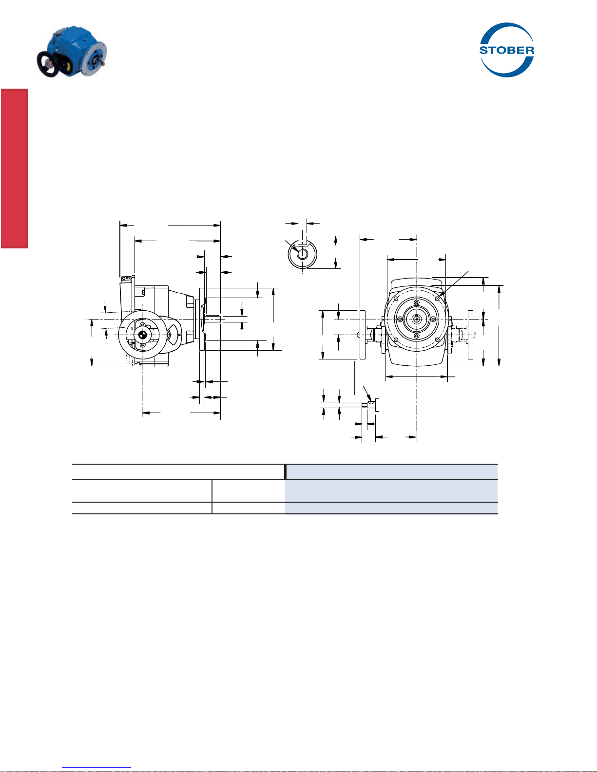
Motor Slide
Adjustment
2.17
5.67
Part No. – 51 lbs.
TD370FK145
Flange Style
145TC Input
143TC Output
ComTrac® Adjustable Speed Drives
2.0 HP @ 1750 RPM
+.0000 / -.0005
11.69
9.88
9.09
2.24
.47
.875
+.0000
-.0005
.12
2.13
1.97
1
/4-20 NC
4.500
+.000
-.001
6.50
.1875
x 1.77 Lg.
5.91
.96
2.05
4.92
.5903
+.0000
-.0005
M10
.20 x .26
.51
4.531.30
Handwheel Shaft Dimensions
5.875
6.69
3
/8-16 NC
4.37
5.94
9.72
Constant Horsepower Range Constant Torque Range
MAXIMUM TRANSITION
RPM
(1)
in.lbs. HP RPM
(1)
in.lbs. HP RPM
2,100 51 1.70 1,162 97 1.79 420 97 0.65
All ratings shown are based on 1750 RPM motor speed and are rated to provide constant torque through the entire speed range. Contact STOBER for
constant horsepower applications.
1)
Speed tolerance at rated load is ±3%. At less than rated load, minimum speed may increase 5%.
2)
The ComTrac drive operates at constant horsepower above transition values and at constant torque below transition values. Note shaded area.
MOTOR MUST BE ORDERED SEPARATELY.
Engineering advances may cause slight changes to the information shown.
(2)
MINIMUM
(1)
in.lbs. HP
10 STOBER Drives Inc. • ComTrac2012 • www.stober.com
Page 13
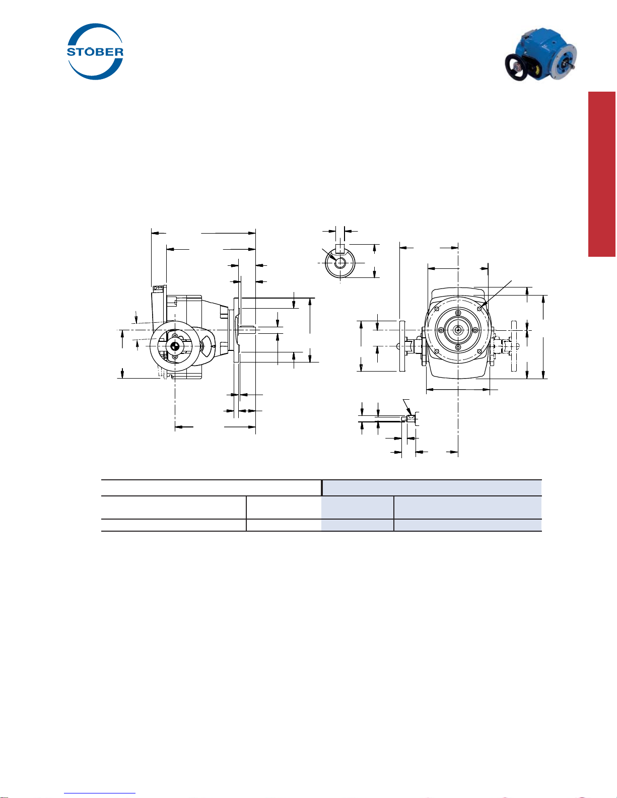
Motor Slide
Adjustment
2.80
7.20
ComTrac® Adjustable Speed Drives
3.0 HP @ 1750 RPM
+.0000 / -.0005
12.48
9.96
9.13
2.24
.47
1.97
+.0000
.12
2.13
.875
-.0005
1
/4-20 NC
4.500
+.000
-.001
6.50
.1875
x 1.77 Lg.
6.81
.96
2.60
6.30
.5903
+.0000
-.0005
M10
.20 x .26
.51
5.241.30
Handwheel Shaft Dimensions
5.875
3
/8-16 NC
5.59
11.57
6.93
8.11
Part No. – 59 lbs.
TD470FK182
Flange Style
182TC Input
143TC Output
Constant Horsepower Range Constant Torque Range
MAXIMUM TRANSITION
RPM
(1)
in.lbs. HP RPM
(1)
in.lbs. HP RPM
2,100 81 2.70 970 177 2.72 420 177 1.18
All ratings shown are based on 1750 RPM motor speed and are rated to provide constant torque through the entire speed range. Contact STOBER for
constant horsepower applications.
1)
Speed tolerance at rated load is ±3%. At less than rated load, minimum speed may increase 5%.
2)
The ComTrac drive operates at constant horsepower above transition values and at constant torque below transition values. Note shaded area.
MOTOR MUST BE ORDERED SEPARATELY.
Engineering advances may cause slight changes to the information shown.
STOBER Drives Inc. • ComTrac2012 • www.stober.com 11
(2)
MINIMUM
(1)
in.lbs. HP
Page 14
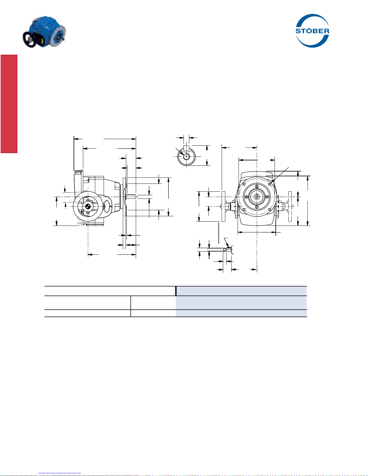
Motor Slide
Adjustment
3.11
8.11
Part No. – 88 lbs.
TD570FK184
Flange Style
184TC Input
182TC Output
ComTrac® Adjustable Speed Drives
5.0 HP @ 1750 RPM
+.0000 / -.0005
15.98
13.39
12.32
2.75
.83
2.40
1.125
+.0000
-.0005
.26
2.62
3
8.500
+.000
-.001
/8-16 NC
9.00
.25
x 2.20 Lg.
8.31
1.24
3.35
7.87
.7871
+.0000
-.0005
M12
.20 x .30
.59
6.541.50
Handwheel Shaft Dimensions
7.250
9.61
1
/2-13 NC
6.30
8.11
13.43
Constant Horsepower Range Constant Torque Range
MAXIMUM TRANSITION
RPM
(1)
in.lbs. HP RPM
(1)
in.lbs. HP RPM
2,100 137 4.56 1,102 266 4.65 420 266 1.77
All ratings shown are based on 1750 RPM motor speed and are rated to provide constant torque through the entire speed range. Contact STOBER for
constant horsepower applications.
1)
Speed tolerance at rated load is ±3%. At less than rated load, minimum speed may increase 5%.
2)
The ComTrac drive operates at constant horsepower above transition values and at constant torque below transition values. Note shaded area.
MOTOR MUST BE ORDERED SEPARATELY.
Engineering advances may cause slight changes to the information shown.
(2)
MINIMUM
(1)
in.lbs. HP
12 STOBER Drives Inc. • ComTrac2012 • www.stober.com
Page 15
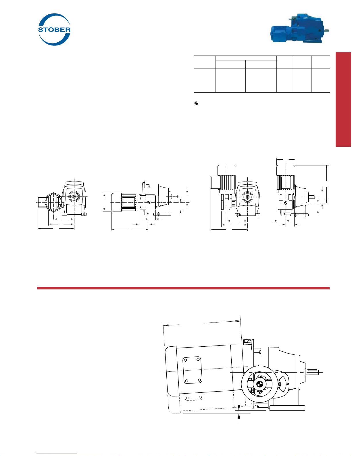
ComTrac® Adjustable Speed Drives
Electric Remote Control
The STOBER Electric Remote Control (ERC) is a compact double
reduction gearmotor which is pinion mounted to the motor slide
track in place of the handwheel. A mechanical clutch within the
unit indicates the end of vertical motor travel in both directions by
making a clicking noise.
The ERC can be operated by push button or other type of control
(not included) to adjust the drive's speed. In many applications
it is advisable to use a limit switch with the ERC to prevent overspeed or underspeed conditions.
Features:
• Speed changes can be made when the unit is stationary or
running.
• STOBER ERC can be quickly and easily added to existing
ComTrac drives without special tools.
• All STOBER ERC units are designed for washdown/severe
duty applications and are available from stock.
• Available voltages:
– 115V, single phase, 60 Hz
– 230/460V, three phase, 60 Hz
4.92
2.09
Table No. 1 ERC – Dimensions (Inches)
ComTrac Model Number
Size Single Phase Three Phase A B C
TD27
ERC27-1 ERC27-2 6.18 7.09 9.72
TD37
TD47
TD57
Motor dimensions may vary slightly from values shown.
Reference point for handwheel center .
2.28
ERC37-1 ERC37-3 6.14 7.05 9.68
ERC47-1 ERC47-3 7.12 8.03 10.67
ERC57-1 ERC57-3 7.56 9.06 11.10
4.92
9.96
2.72
1.85
A
B
C
ERC for ComTrac sizes: TD27, TD37, and TD47.
9.96
2.72
1.85
A
B
C
ERC for ComTrac sizes: TD57
2.09
2.28
Motor Clearance
On some TD27 ComTrac units, the motor can be lower than the base of the unit when adjusted to the slowest setting. The following formula
will determine a value based on the length of the motor to be installed.
XX = .055 x B (When "B" = motor length)
B
STOBER Drives Inc. • ComTrac2012 • www.stober.com 13
XX
Footed unit shown for illustration only.
This style is no longer available.
Page 16

ComTrac® Adjustable Speed Drives
Selection and Performance Characteristics
Selection:
The ComTrac drives shown in the selection tables are rated for
constant torque operation – where required horsepower varies directly in proportion to the speed of the driven machine. All ratings
shown are based upon standard NEMA C-face motor designs with
1750 RPM input speed. Contact STOBER technical support for
selection assistance for motor speeds other than 1750 RPM.
Basic selection procedure is as follows:
1. Establish the maximum horsepower required by the driven
machine at maximum speed.
If only the driven equipment's maximum torque (T) require-
ment is known, use the following formula to convert the torque
value to horsepower: T x RPM
HP =
63,025
2. Select the drive which meets or exceeds the maximum HP
rating of the driven machine at maximum speed.
Since the typical ComTrac application requires constant torque
over the entire speed range, there will be an adequate service
factor to protect the traction ring from damage.
Use the output speed ratings shown in the tables to select an output speed which meets or exceeds the requirement of the driven
machine. Read across the table to determine if the drive's actual
minimum and maximum speed, torque, and horsepower ratings
meet the requirements of the driven equipment.
If the maximum output speed shown in the table is too low, go to
the next higher speed. Should the torque or horsepower ratings
shown be below the driven equipment's requirements, consult the
next higher horsepower rating in the selection data.
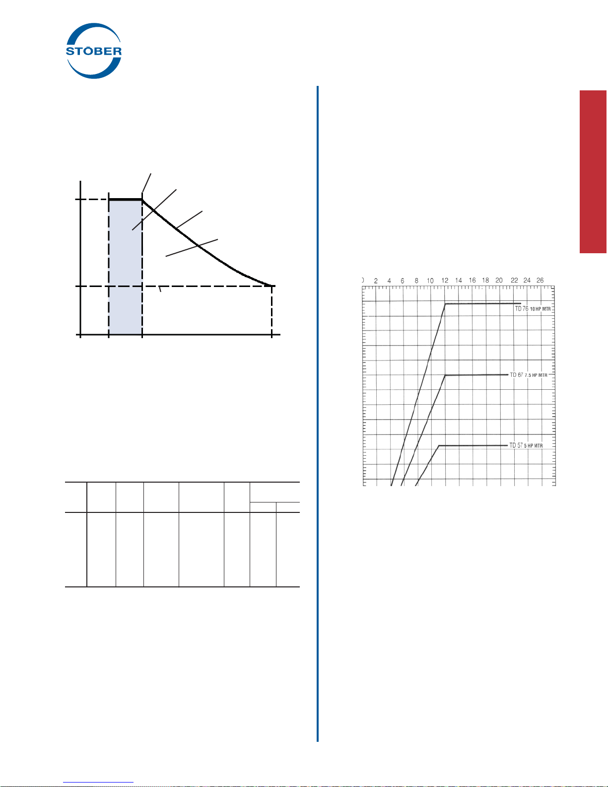
Performance Characteristics
Because of its mechanical operation, the ComTrac drive generally produces constant output torque. While the induction motor
produces constant horsepower and constant speed, the two are
combined in a manner that provides optimum utility and economy.
As the ComTrac Performance Chart shows, the drive has two
operating regions.
1. Constant torque between the drive's absolute minimum
speed and transition speed.
2. Constant horsepower between the transition speed and
maximum speed.
When selecting a ComTrac drive, it is important to choose a unit
which will not allow the cone and ring system to be over powered
by the motor. As shown in the ComTrac Performance Chart, ComTrac drives should always be selected so that the output torque
required is well below the torque capability of the cone and the
ring system.
Motor Performance
The ratings shown in the ComTrac selection tables are based on
standard NEMA motors with the following specifi cations:
• 1750 RPM speed
• 60 Hz operation
Application Matched Options
Several options for ComTrac drives, such as remote controls, are
included in this catalog. In addition, the following options are also
available:
• 50 Hz operation for export
• Motor enclosures
For application and selection assistance for these options and
others, contact your local STOBER distributor.
Non-Standard Application Conditions
For constant horsepower applications, or any of the nonstandard
application conditions shown below, contact STOBER technical
support.
Unusual Loading Conditions:
• Heavy shock load
• High inertia load
• Load reversals or overhauling loads
• More than ten starts per hour
Unusual Environmental Conditions:
• High altitudes – above 5000 feet
• Corrosive chemicals
• Excessively dusty or abrasive environments
• Ambient temperatures below 25° F or above 125° F
Nonstandard Motors:
• Motor frame sizes other than those shown in the tables
Nonstandard Mounting:
• Output shaft up or down (V5 or V6 mounting)
Not Recommended for Mounting:
• Explosive environment of any type
14 STOBER Drives Inc. • ComTrac2012 • www.stober.com
Page 17
ComTrac® Adjustable Speed Drives
Selection and Performance Characteristics
Graph No. 1 ComTrac Performance Chart
Overhung Loads
Torque Capacity of the Cone/Ring System
Constant Torque Operating Range
Constant Motor Output HP
Constant HP Operating
Range
Graph No. 2 ComTrac Series 0F Output HP
7
Torque Rating at Maxi-
mum Speed
TRANSITION SPEED
Output Torque (in.lbs.)
Min. Trans. Max.
Output Speed (RPM)
Table No. 1
ComTrac Series 0F Specifi cations
Output C-Face Output Speed
Motor NEMA Torque Model Output Speed Range (RPM)
HP Frame in.lbs. Number Flange Range Max. Min.
.50 56C 16
.75 56C 24
1.00 143TC 32
1.50 145TC 48
2.00 145TC 64
3.00 182TC 99
5.00 184TC 168
Minimum output torque rating based on 1750 RPM maximum input
speed.
TD270F 56C 7:1 2180 311
TD270F 56C 7:1 2180 311
TD270F 56C 7:1 2180 311
TD370F 143/145TC 5:1 2100 420
TD370F 143/145TC 5:1 2100 420
TD470F 143/145TC 5:1 2100 420
TD570F 182/184TC 5:1 2100 420
6
5
4
3
2
1
Output Horsepower (HP) Rating
0 2 4 6 8 10 12 14 16 18 20 22 24 26
Output Speed (RPM x 10)
TD57, 5 HP motor
TD47, 3 HP motor
TD37, 2 HP motor
TD37, 1.5 HP motor
TD27 .75 HP motor
TD27, .5 HP motor
TD27, 1.0 HP motor
STOBER Drives Inc. • ComTrac2012 • www.stober.com 15
Page 18
ComTrac® Adjustable Speed Drives
Installation Instructions
ComTrac Series 0F
Units with C-face input and output are designed to attach to any speed reducer with
a NEMA C-face input. Care must be taken
to follow the speed reducer manufacturer's
recommended mounting instructions.
NOTE: ComTrac Series 0F drives do not
have mounting feet. The drive and motor assembly is mounted on
the speed reducer which must support the reducer, ComTrac, and
the motor. If there is concern for the ability of the reducer mounting feet to support the entire assembly, a larger speed reducer
may be required.
The output shaft of the ComTrac drive is shipped from the factory
with a protective coating. Remove this coating with a suitable
nonfl ammable solvent. Precaution must be taken not to allow the
solvent to contact the output shaft oil seal, since damage to the
seal may occur.
Motor Installation
Step 4 – Through the access hole, tighten the hex socket screw
on the motor clamp hub to the tightening torque shown in the table
below. The correct size hex wrench is
provided. DO NOT OVERTIGHTEN.
SHOWN WITHOUT MOTOR FOR
DEMONSTRATION.
Table No. 1
Clamp Ring Setscrew Tightening Torque
ComTrac Size in. lbs.
TD27 88.5
TD37 88.5
TD47 221
TD57 434
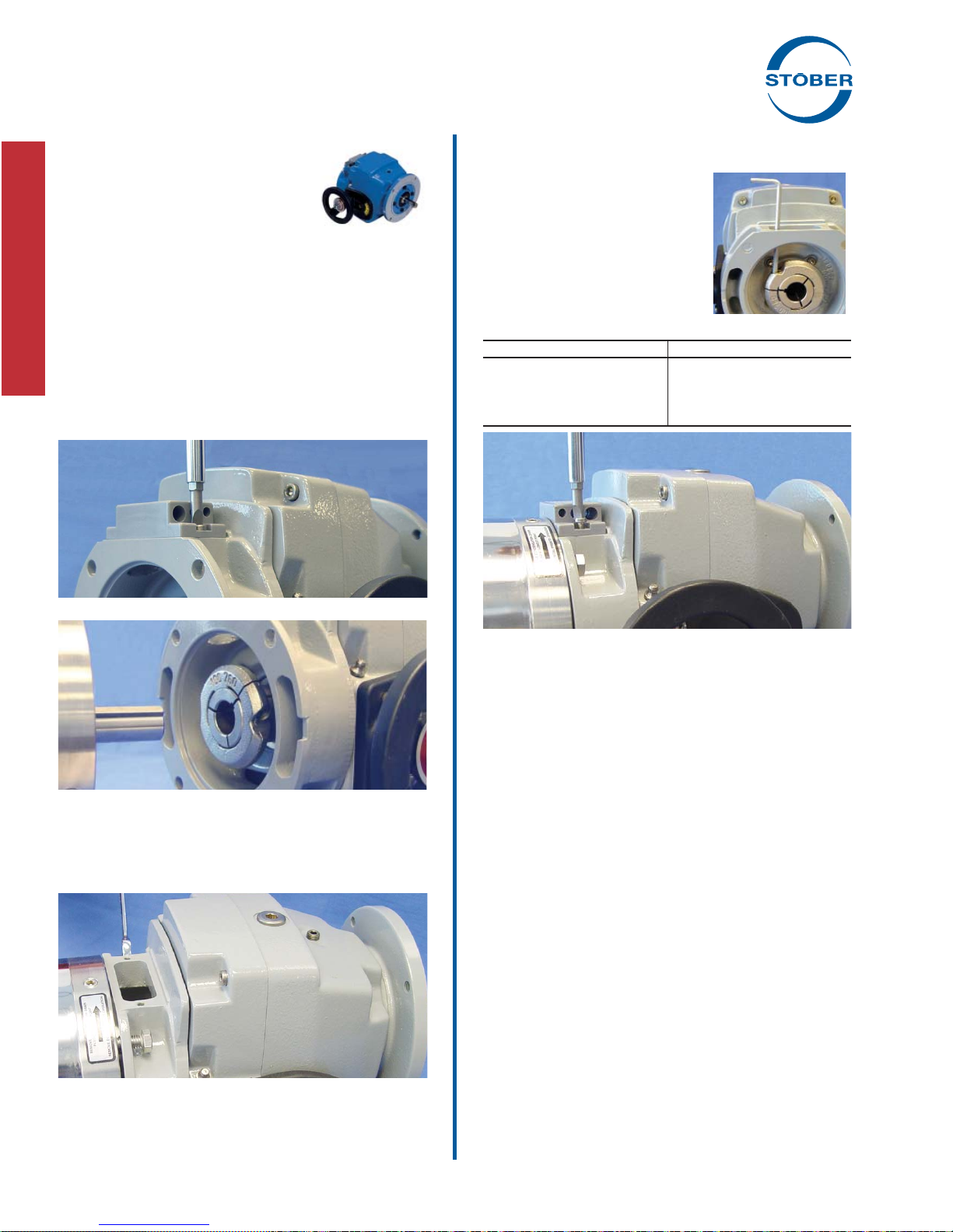
Step 1 – Remove the access cover.
Step 2 – Lubricate and insert keyed motor shaft into the slotted bore
of the drive cone shaft.
NOTE: For ease of installation, secure the key to the motor shaft.
(Staking near the end of the keyway or a temporary adhesive
works well.)
Step 5 – Reattach access cover.
When couplings, gears, sprockets or pulleys are mounted on the
output shaft, be sure to mount them as close as possible to the
housing to minimize the effects of overhung loads on shafts and
bearings.
CAUTION: Do not drive couplings, sprockets, gears or pulleys
onto the output shaft with hard hammer blows, since damage to
internal gears or bearings will result. All output shafts have a metric centering thread for attachment of transmission devices. They
can be pulled on gently with a bolt and plate.
Step 3 – Tighten the four motor fl ange bolts.
IMPORTANT: Jog the motor several revolutions before
tightening the motor clamp to assure proper position of the
drive cone on the motor shaft. See Page 5 for illustration.
16 STOBER Drives Inc. • ComTrac2012 • www.stober.com
Page 19
ComTrac® Adjustable Speed Drives
Installation Instructions
Handwheel Position
ComTrac drives are furnished with the speed control handwheel
on the left, as viewed from the output shaft end of the drive. If it is
necessary that the handwheel be moved to the opposite side, this
can be accomplished very easily with the hex wrenches provided
with each drive.
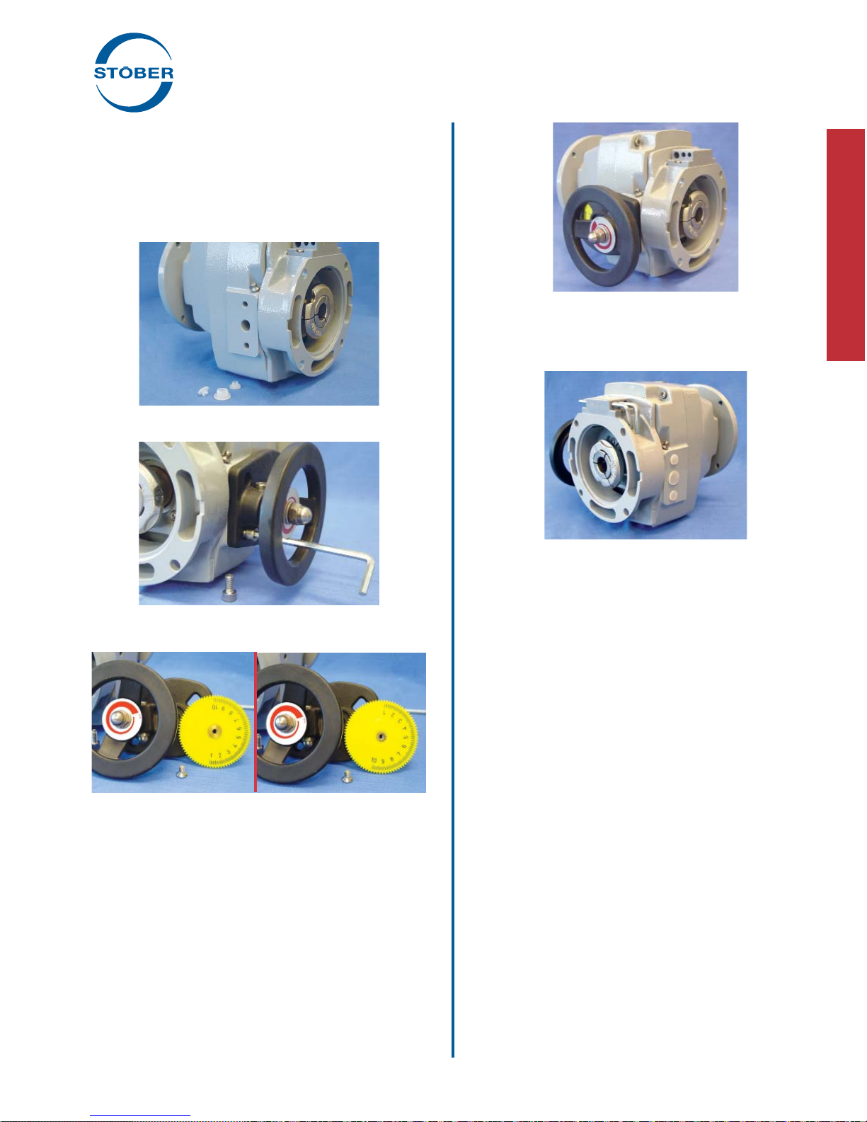
Procedure for Changing Handwheel Position:
Step 1 – Remove the three (3) plastic plugs in the housing on the
side opposite the handwheel.
Step 5 – Place pinion, handwheel and indicator on desired side of the
drive's housing (from where the three plastic plugs were removed),
and secure with the two socket-head capscrews removed previously.
Step 2 – Remove the handwheel and indicator assembly by removing the two (2) socket-head capscrews which secure the handwheel
indicator assembly to the housing.
Step 3 – Turn the yellow numbered position indicator wheel around
by removing the slotted screw. (Be sure to remove the tape covering
to expose position numbers on the other side of the wheel.)
Step 4 – Replace the slotted screw.
Step 6 – Relocate the plastic plugs to the holes where the handwheel
was originally mounted.
Lubricate the motor slide and rack (both sides) with one (1) stroke
with a grease gun through the fi ttings provided in the housing.
IMPORTANT: Do not over lubricate the motor slide. Under normal conditions, maintenance of the motor slide and rack should
only be required one time per year.
Electric Remote Control (ERC) Installation
The Electric Remote Control consists of a small gearmotor
mounted on the ComTrac drive in place of the manual handwheel
control.
Procedure
Attaching the ERC is accomplished by simply removing the two
(2) socket-head capscrews that secure the handwheel and indicator assembly to the drive's housing.
Replace the handwheel/indicator assembly with the ERC and
secure it to the housing with the same two screws.
Lubricate the motor slide and rack (both sides) with one (1) stroke
with a grease gun through fi ttings in the housing.
The ERC is operated by pushbutton or other form of contact
(furnished by customer). A mechanical clutch is contained within
the gearmotor which indicates the end position of travel, in either
direction, by making a clicking noise. Also, the ERC can be operated while the drive is stationary.
Power required for the ERC is 230 volt, 3 phase, 60 hertz, or 115
volt, single phase, 60 hertz.
The wiring diagram for the ERC is inside the motor's conduit box.
The ERC motor and drive should be protected from excessive
dust, fl ying chips, and oil splashes.
STOBER Drives Inc. • ComTrac2012 • www.stober.com 17
Page 20
ComTrac® Adjustable Speed Drives
Maintenance and Lubrication Instructions
In order to obtain long life and trouble-free operation from your
ComTrac
®
drive, it is essential that proper installation and operat-
ing procedures be followed.
The torque required by the application must not exceed the
reducer torque capacity shown on the nameplate. For safety purposes a safety coupling should be installed between the reducer
and the driven load. Otherwise, overload may cause damage to
the interior parts of the reducer which may result in breaking the
reducer housing. As a result, persons could be injured by fl ying
parts or splashing hot gear oil.
This catalog includes basic directions for mounting and start-up of
the ComTrac
®
drive, as well as lubrication information. Failure to
follow these instructions will void the drive's warranty.
If you have questions about the installation, operation or mainte-
nance of your ComTrac
®
drive, please contact your local STOBER
distributor for assistance.
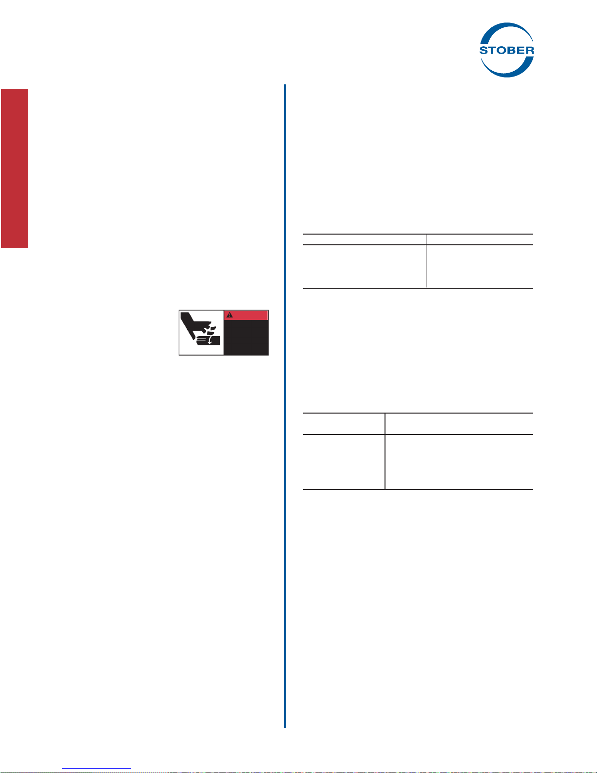
WARNING:
Safety is the most important consideration when operating any
type of drive. Through proper application, safe handling methods,
and wearing appropriate clothing, you can prevent accidents and
injury to yourself and fellow workers.
®
The shafts of ComTrac
can cut off or severely injure hands,
fi ngers, and arms. Use appropriate
guards for shafts and other rotating
parts at all times. Follow all directions
in the service instruction manual.
drives rotate at very high speeds and
WARNING
Cover rotating
parts with safety
guard before
turning on
power.
Obey all federal, state and local safety
regulations when operating the drive.
• Always be sure electrical power is off while making electrical
connections and during installation and maintenance of the
unit.
• Keep clothing, hands, and tools away from ventilation openings on motors and from all rotating parts during operation.
• Lift drive with a double rope sling or other proper lifting
equipment of adequate strength. Make sure load is secured
and balanced to prevent shifting when unit is being moved.
Lifting heavy drives by hand may be dangerous and should be
avoided.
• The intended use of lifting lugs is to handle the weight of the
unit only. Never use a lifting lug to lift attached assemblies.
• Never operate drive at speeds higher than those shown on
the nameplate, or personal injury may result. Contact STOBER Drives Inc., if there is any change of operating conditions
from those for which the unit was originally sold (as stamped
on the nameplate). Failure to comply could result in personal
injury and or machinery damage.
• Always follow good safety practices at all times.
Each drive is tested before delivery. Before installation, however,
it is advisable to examine the unit for possible damage which
might have occurred during transit. If damage is discovered, it
should be immediately reported to the transport agent.
If installation is delayed after receipt of the MGS speed reducer,
the drive should be stored in a clean, dry place until put into service. Long term storage requires special procedures. If not kept
in a heated, dry area, consult STOBER Drives, Inc. for storage
instructions.
NOTE: If it is necessary to clean drive shafts, take care to protect
the oil seals.
IMPORTANT: Do not use any device to hammer the unit onto the
output shaft during installation since the bearing races could be
damaged.
Maintenance and Lubrication
WARNING: Before beginning any work on the ComTrac drive
system, disconnect the power source (lock-out the motor
starter, and unload breakers, backstops, etc.). Failure to
do so may cause serious personal injury and/or machinery
damage.
Series 0F
These units require lubricant only in the cam and bearing
chamber and are shipped with the lubricant in them. There is a
suffi cient quantity of lubricant to allow mounting the non-geared
ComTrac Drive in any position.
Table No. 1
Series "0" – Bearing and Cam Chamber Oil Quantity
ComTrac Size fl uid oz.
For normal indoor installations the handwheel or ERC control pinion and motor slide rack should be lubricated through the grease
fi tting every six months using NLGI No. 2 grease. One stroke of
a grease gun is suffi cient. When the drive is operating under wet
conditions, increase the frequency of lubrication to once a month.
Under normal operating conditions the synthetic oil in the cam
and bearing chamber does not need to be replaced. If for any
reason some quantity of lubricant is lost, remove the rest of the
lubricant from the cam and bearing chamber and replace it with
the type and quantity of oil listed in the lubrication table shown.
Table No. 2 Bearing and Cam Oil Manufacturers
Lubricant
Manufacturer AGMA Lubricant ( No. 5EP)
Darmex 9140
Exxon Spartan 220
Mobil * Mobilgear 630
Gulf HD220
Keystone KSL-366
Lubriplate APG90
* Mobile SHC626 is used for the initial fi ll. If refi ll is necessary, any of
the above products may be used.
For installations in the food, dairy, beverage and baking industries, where special lubricants are required, a suitable grease of
the user's preference should be used.
When a ComTrac Drive with C-face output (Series 0F) is attached
to a speed reducer, follow the manufacturer's lubrication instructions for the reducer mounting before start-up.
TD27-0 1.5
TD37-0 1.7
TD47-0 1.9
TD57-0 4.4
18 STOBER Drives Inc. • ComTrac2012 • www.stober.com
Page 21
"C" Series – Concentric Helical
®
MGS
Adjustable Speed Drives
Performance Specifi cations:
• Horsepower ratings – from 1/2 to 5
• Output speeds – available from 1139 to 8 RPM
• Speed range – 5:1 to 7:1
• Output torques – up to 59,782 in.lbs.
• NEMA frames – from 56C to 215TC
STOBER can offer a wider variety of sizes, ratios, and mounting
positions than ever before by utilizing MGS Reducers and ComTrac Adjustable Speed Drives.
These versatile gear drives offer you performance, durability, and
economy for a wide range of variable speed applications. High
effi ciency helical gearing keeps motor size to a minimum while
conserving energy.
Table No. 1 "C"Series – Output Shaft Diameter
Base Inches
Module Standard Stainless Steel Metric
C002 .750 .750 20
(1)
STOBER Drives Inc. • ComTrac2012 • www.stober.com 19
(1)
C102/C103 1.000 1.000 25
C202/C203 1.250 1.250 30
C302/C303 1.250 1.250 40
C402/C403 1.625 1.625 40
C512/C513 1.625 1.625 40
C612/C613 2.125 2.125 50
C712/C713 2.375 – 60
C812/C813 2.875 – 70
Contact STOBER Drives for availability.
Page 22
"C" Series – MGS Adjustable Speed Drive
Selection Data
Speed Range Maximum Transition
Output RPM
(1)
Part Number Torque Torque Torque
(2)
Minimum
Max. Min. RPM in.lbs. RPM in.lbs. RPM in.lbs.
.50 HP, 1750 RPM Motor Continued on next page
1,139 163 C002_0020 TD270K 050-050 1,139 22 163 129 163 129
1,045 149
822 117
742 106
686 98
593 85
586 84
548 78
543 78
486 69
453 65
449 64
391 56
387 55
361 52
295 42
292 42
276 39
275 39
247 35
244 35
221 32
197 28
181 26
162 23
145 21
130 19
110 16
98 14
97 14
91 13
91 13
81 12
80 11
73 10
73 10
65 9.3
65 9.3
56 8.0
1)
Speed tolerance at rated load is ±3%. At less than rated load, minimum speed may increase 5%.
2)
The ComTrac drive operates at constant horsepower above transition values and at constant torque below transition values. Note shaded area.
Engineering advances may cause slight changes to the information shown.
C102_0022 TD270K 050-050 1,045 25 149 140 149 140
C002_0028 TD270K 050-050 822 31 117 178 117 178
C002_0031 TD270K 050-050 742 35 106 198 106 198
C002_0033 TD270K 050-050 686 37 98 214 98 214
C002_0038 TD270K 050-050 593 43 85 247 85 247
C102_0039 TD270K 050-050 586 44 84 250 84 250
C002_0041 TD270K 050-050 548 47 78 267 78 267
C102_0042 TD270K 050-050 543 47 78 270 78 270
C002_0047 TD270K 050-050 486 53 69 302 69 302
C102_0050 TD270K 050-050 453 57 65 324 65 324
C002_0051 TD270K 050-050 449 57 64 326 64 326
C002_0058 TD270K 050-050 391 66 56 375 56 375
C102_0059 TD270K 050-050 387 66 55 379 55 379
C002_0063 TD270K 050-050 361 71 52 406 52 406
C002_0077 TD270K 050-050 295 87 42 497 42 497
C102_0078 TD270K 050-050 292 88 42 502 42 502
C002_0082 TD270K 050-050 276 93 39 531 39 531
C102_0083 TD270K 050-050 275 93 39 532 39 532
C002_0092 TD270K 050-050 247 104 42 531 35 531
C102_0093 TD270K 050-050 244 105 35 601 35 601
C002_0105 TD270K 050-050 221 116 44 531 32 531
C002_0115 TD270K 050-050 197 130 45 531 28 531
C002_0125 TD270K 050-050 181 141 46 531 26 531
C002_0140 TD270K 050-050 162 159 48 531 23 531
C002_0155 TD270K 050-050 145 176 49 531 21 531
C002_0175 TD270K 050-050 130 197 49 531 19 531
C002_0210 TD270K 050-050 110 233 50 531 16 531
C002_0230 TD270K 050-050 98 261 51 531 14 531
C102_0240 TD270K 050-050 97 265 23 1,063 14 1,063
C002_0250 TD270K 050-050 91 281 51 531 13 531
C102_0250 TD270K 050-050 91 283 23 1,063 13 1,063
C002_0280 TD270K 050-050 81 315 51 531 12 531
C102_0280 TD270K 050-050 80 319 24 1,063 11 1,063
C002_0310 TD270K 050-050 73 352 50 531 10 531
C102_0310 TD270K 050-050 73 350 24 1,063 10 1,063
C002_0350 TD270K 050-050 65 394 50 531 9.3 531
C102_0350 TD270K 050-050 65 395 25 1,063 9.3 1,063
C202_0410 TD270K 050-050 56 460 14 1,772 8.0 1,772
Housing Styles
N – Foot Mounted F – Round Flange Q – Square Flange G – T apped Holes
See page 78 for mounting positions.
Housing Style Q is available on special order.
20 STOBER Drives Inc. • ComTrac2012 • www.stober.com
Output Shaft Diameter (inches)
See Page 21 for other options.
Base Module Dia. Base Module Dia.
C002 .7500 C512/C513 1.6250
C102/C103 1.0000 C612/C613 2.1250
C202/C203 1.2500 C712/C713 2.3750
C302/C303 1.2500 C812/C813 2.8750
C402/C403 1.6250
Page 23
"C" Series – MGS Adjustable Speed Drive
Selection Data
Speed Range Maximum Transition
Output RPM
(1)
Part Number Torque Torque Torque
(2)
Minimum
Max. Min. RPM in.lbs. RPM in.lbs. RPM in.lbs.
.50 HP, 1750 RPM Motor Continued
55 7.8 C102_0420 TD270K 050-050 55 468 25 1,063 7.8 1,063
48 6.9
46 6.6
46 6.5
40 5.8
37 5.2
36 5.2
33 4.7
30 4.3
29 4.1
28 4.0
26 3.7
25 3.6
25 3.6
25 3.6
21 3.0
21 3.0
21 3.0
21 3.1
17 2.4
17 2.4
13 1.8
13 1.8
13 1.8
13 1.9
11 1.5
11 1.5
10 1.5
10 1.5
9 1.2
8 1.2
8 1.2
C102_0470 TD270K 050-050 48 528 25 1,063 6.9 1,063
C202_0490 TD270K 050-050 46 554 14 1,772 6.6 1,772
C302_0500 TD270K 050-050 46 560 7 3,100 6.5 3,100
C202_0560 TD270K 050-050 40 635 15 1,772 5.8 1,772
C302_0620 TD270K 050-050 37 697 8 2,932 5.2 2,932
C402_0630 TD270K 050-050 36 704 5 4,029 5.2 4,029
C302_0700 TD270K 050-050 33 786 8 3,100 4.7 3,100
C613_0760 TD270K 050-050 30 841 4 4,815 4.3 4,815
C203_0800 TD270K 050-050 29 883 15 1,772 4.1 1,772
C403_0810 TD270K 050-050 28 896 4 4,872 4.0 4,872
C613_0880 TD270K 050-050 26 972 4 5,566 3.7 5,566
C203_0910 TD270K 050-050 25 1,012 15 1,772 3.6 1,772
C303_0910 TD270K 050-050 25 1,007 8 3,100 3.6 3,100
C403_0900 TD270K 050-050 25 1,002 5 4,872 3.6 4,872
C203_1090 TD270K 050-050 21 1,211 15 1,772 3.0 1,772
C303_1080 TD270K 050-050 21 1,200 8 3,100 3.0 3,100
C503_1090 TD270K 050-050 21 1,205 3 6,900 3.0 6,900
C613_1060 TD270K 050-050 21 1,176 3 6,736 3.1 6,736
C203_1360 TD270K 050-050 17 1,509 15 1,772 2.4 1,772
C303_1350 TD270K 050-050 17 1,502 9 3,100 2.4 3,100
C303_1800 TD270K 050-050 13 2,002 9 3,100 1.8 3,100
C403_1800 TD270K 050-050 13 2,002 5 4,872 1.8 4,872
C503_1810 TD270K 050-050 13 2,004 3 7,086 1.8 7,086
C613_1750 TD270K 050-050 13 1,944 2 11,133 1.9 11,133
C503_2160 TD270K 050-050 11 2,395 4 7,086 1.5 7,086
C613_2130 TD270K 050-050 11 2,364 2 11,515 2.5 11,515
C303_2170 TD270K 050-050 10 2,408 8 3,100 1.5 3,100
C403_2170 TD270K 050-050 10 2,406 5 4,872 1.5 4,872
C613_2660 TD270K 050-050 9 2,955 2 11,515 1.2 11,515
C403_2700 TD270K 050-050 8 2,997 5 4,872 1.2 4,872
C503_2710 TD270K 050-050 8 3,001 4 7,086 1.2 7,086
Selection Procedure:
A. Determine the MGS/ComTrac combination according to the Input
HP of the application and the Output RPM nearest the required
maximum speed.
B. Verify that the output torque will suffi ciently meet the application
requirements.
C. Complete the Part No. per the example by adding the Housing Style
letter ("N", "F", "Q" or "G") as required.
STOBER Drives Inc. • ComTrac2012 • www.stober.com 21
Part No. Explanation
C 5 0 2 N 0620 TD370K140 – 200 W
Washdown, when required
Rated for HP (
Non-geared
Ratio of MGS Unit (
Housing Style
No. of Gear Reductions
Generation No.
Unit No.
Concentric Helical
TD37 ComTrac Unit, 145TC Input
0620 = 62.0:1)
200 = 2.00)
Page 24
"C" Series – MGS Adjustable Speed Drive
Selection Data
Speed Range Maximum Transition
Output RPM
(1)
Part Number Torque Torque Torque
(2)
Minimum
Max. Min. RPM in.lbs. RPM in.lbs. RPM in.lbs.
.75 HP, 1750 RPM Motor Continued on next page
1,139 163 C002_0020 TD270K 050-075 1,139 33 282 129 163 129
1,045 149
822 117
742 106
686 98
593 85
586 84
548 78
543 78
486 69
453 65
449 64
391 56
387 55
361 52
295 42
292 42
276 39
275 39
247 35
244 35
221 32
197 28
181 26
162 23
145 21
130 19
128 18
110 16
109 16
98 14
97 14
91 13
91 13
81 12
80 11
73 10
73 10
65 9.3
1)
Speed tolerance at rated load is ±3%. At less than rated load, minimum speed may increase 5%.
2)
The ComTrac drive operates at constant horsepower above transition values and at constant torque below transition values. Note shaded area.
Engineering advances may cause slight changes to the information shown.
C102_0022 TD270K 050-075 1,045 36 259 140 149 140
C002_0028 TD270K 050-075 822 46 204 178 117 178
C002_0031 TD270K 050-075 742 51 184 198 106 198
C002_0033 TD270K 050-075 686 55 170 214 98 214
C002_0038 TD270K 050-075 593 64 147 247 85 247
C102_0039 TD270K 050-075 586 65 145 250 84 250
C002_0041 TD270K 050-075 548 69 136 267 78 267
C102_0042 TD270K 050-075 543 70 135 270 78 270
C002_0047 TD270K 050-075 486 78 120 302 69 302
C102_0050 TD270K 050-075 453 84 112 324 65 324
C002_0051 TD270K 050-075 449 85 111 326 64 326
C002_0058 TD270K 050-075 391 97 97 375 56 375
C102_0059 TD270K 050-075 387 98 96 379 55 379
C002_0063 TD270K 050-075 361 105 89 406 52 406
C002_0077 TD270K 050-075 295 129 73 497 42 497
C102_0078 TD270K 050-075 292 130 72 502 42 502
C002_0082 TD270K 050-075 276 138 68 531 39 531
C102_0083 TD270K 050-075 275 138 68 532 39 532
C002_0092 TD270K 050-075 247 154 70 531 35 531
C102_0093 TD270K 050-075 244 156 60 601 35 601
C002_0105 TD270K 050-075 221 172 72 531 32 531
C002_0115 TD270K 050-075 197 193 73 531 28 531
C002_0125 TD270K 050-075 181 210 74 531 26 531
C002_0140 TD270K 050-075 162 235 75 531 23 531
C002_0155 TD270K 050-075 145 261 75 531 21 531
C002_0175 TD270K 050-075 130 293 75 531 19 531
C102_0175 TD270K 050-075 128 296 35 1,063 18 1,063
C002_0210 TD270K 050-075 110 346 75 531 16 531
C102_0210 TD270K 050-075 109 348 36 1,063 16 1,063
C002_0230 TD270K 050-075 98 388 74 531 14 531
C102_0240 TD270K 050-075 97 393 37 1,063 14 1,063
C002_0250 TD270K 050-075 91 417 74 531 13 531
C102_0250 TD270K 050-075 91 420 37 1,063 13 1,063
C002_0280 TD270K 050-075 81 468 73 531 12 531
C102_0280 TD270K 050-075 80 474 37 1,063 11 1,063
C002_0310 TD270K 050-075 73 522 72 531 10 531
C102_0310 TD270K 050-075 73 519 37 1,063 10 1,063
C102_0350 TD270K 050-075 65 586 38 1,063 9.3 1,063
Housing Styles
N – Foot Mounted F – Round Flange Q – Square Flange G – T apped Holes
See page 78 for mounting positions.
Housing Style Q is available on special order.
22 STOBER Drives Inc. • ComTrac2012 • www.stober.com
Output Shaft Diameter (inches)
See Page 21 for other options.
Base Module Dia. Base Module Dia.
C002 .7500 C512/C513 1.6250
C102/C103 1.0000 C612/C613 2.1250
C202/C203 1.2500 C712/C713 2.3750
C302/C303 1.2500 C812/C813 2.8750
C402/C403 1.6250
Page 25
"C" Series – MGS Adjustable Speed Drive
Selection Data
Speed Range Maximum Transition
Output RPM
(1)
Part Number Torque Torque Torque
(2)
Minimum
Max. Min. RPM in.lbs. RPM in.lbs. RPM in.lbs.
.75 HP, 1750 RPM Motor Continued
65 9.2 C202_0350 TD270K 050-075 65 588 22 1,772 9.2 1,772
56 8.0
55 7.8
48 6.9
49 6.9
46 6.6
46 6.5
40 5.8
41 5.8
37 5.2
36 5.2
33 4.7
30 4.3
29 4.1
28 4.0
28 4.0
26 3.7
25 3.6
25 3.6
25 3.6
21 3.0
21 3.0
21 3.0
21 3.1
17 2.4
17 2.4
13 1.8
13 1.8
13 1.8
13 1.9
11 1.5
11 1.8
10 1.5
9 1.2
8 1.2
8 1.2
C202_0410 TD270K 050-075 56 683 22 1,772 8.0 1,772
C102_0420 TD270K 050-075 55 695 38 1,063 7.8 1,063
C102_0470 TD270K 050-075 48 784 37 1,063 6.9 1,063
C202_0470 TD270K 050-075 49 783 22 1,772 6.9 1,772
C202_0490 TD270K 050-075 46 823 22 1,772 6.6 1,772
C302_0500 TD270K 050-075 46 832 12 3,100 6.5 3,100
C202_0560 TD270K 050-075 40 943 23 1,772 5.8 1,772
C302_0560 TD270K 050-075 41 938 12 3,100 5.8 3,100
C302_0620 TD270K 050-075 37 1,035 13 2,932 5.2 2,932
C402_0630 TD270K 050-075 36 1,045 9 4,029 5.2 4,029
C302_0700 TD270K 050-075 33 1,168 13 3,100 4.7 3,100
C613_0760 TD270K 050-075 30 1,249 7 4,815 4.3 4,815
C203_0800 TD270K 050-075 29 1,311 22 1,772 4.1 1,772
C303_0800 TD270K 050-075 28 1,325 13 3,100 4.0 3,100
C403_0810 TD270K 050-075 28 1,331 7 4,872 4.0 4,872
C613_0880 TD270K 050-075 26 1,444 6 5,566 3.7 5,566
C203_0910 TD270K 050-075 25 1,503 22 1,772 3.6 1,772
C303_0910 TD270K 050-075 25 1,495 13 3,100 3.6 3,100
C403_0900 TD270K 050-075 25 1,488 8 4,872 3.6 4,872
C303_1080 TD270K 050-075 21 1,783 13 3,100 3.0 3,100
C403_1080 TD270K 050-075 21 1,774 8 4,872 3.0 4,872
C503_1090 TD270K 050-075 21 1,790 5 6,900 3.0 6,900
C613_1060 TD270K 050-075 21 1,747 5 6,736 3.1 6,736
C303_1350 TD270K 050-075 17 2,231 13 3,100 2.4 3,100
C403_1350 TD270K 050-075 17 2,218 8 4,872 2.4 4,872
C303_1800 TD270K 050-075 13 2,973 12 3,100 1.8 3,100
C403_1800 TD270K 050-075 13 2,973 8 4,872 1.8 4,872
C503_1810 TD270K 050-075 13 2,976 5 7,086 1.8 7,086
C613_1750 TD270K 050-075 13 2,888 3 11,133 1.9 11,133
C503_2160 TD270K 050-075 11 3,557 6 7,086 1.5 7,086
C613_2130 TD270K 050-075 11 3,511 3 11,515 1.5 11,515
C403_2170 TD270K 050-075 10 3,574 8 4,872 1.5 4,872
C613_2660 TD270K 050-075 9 4,388 3 11,515 1.2 11,515
C403_2700 TD270K 050-075 8 4,451 8 4,872 1.2 4,872
C503_2710 TD270K 050-075 8 4,457 6 7,086 1.2 7,086
Selection Procedure:
A. Determine the MGS/ComTrac combination according to the Input
HP of the application and the Output RPM nearest the required
maximum speed.
B. Verify that the output torque will suffi ciently meet the application
requirements.
C. Complete the Part No. per the example by adding the Housing Style
letter ("N", "F", "Q" or "G") as required.
STOBER Drives Inc. • ComTrac2012 • www.stober.com 23
Part No. Explanation
C 5 0 2 N 0620 TD370K140 – 200 W
Washdown, when required
Rated for HP (
Non-geared
Ratio of MGS Unit (
Housing Style
No. of Gear Reductions
Generation No.
Unit No.
Concentric Helical
TD37 ComTrac Unit, 145TC Input
0620 = 62.0:1)
200 = 2.00)
Page 26
"C" Series – MGS Adjustable Speed Drive
Selection Data
Speed Range Maximum Transition
Output RPM
(1)
Part Number Torque Torque Torque
(2)
Minimum
Max. Min. RPM in.lbs. RPM in.lbs. RPM in.lbs.
1.0 HP, 1750 RPM Motor Continued on next page
1,139 163 C002_0020 TD270K 140-100 1,139 46 411 129 163 129
1,045 149
822 117
742 106
686 98
593 85
586 84
548 78
543 78
486 69
453 65
449 64
391 56
387 55
361 52
295 42
292 42
276 39
275 39
247 35
244 35
221 32
197 28
181 26
183 26
162 23
162 23
145 21
145 21
130 19
128 18
110 16
109 16
98 14
97 14
96 14
91 13
92 13
80 11
81 12
73 10
74 11
1)
Speed tolerance at rated load is ±3%. At less than rated load, minimum speed may increase 5%.
2)
The ComTrac drive operates at constant horsepower above transition values and at constant torque below transition values. Note shaded area.
Engineering advances may cause slight changes to the information shown.
C102_0022 TD270K 140-100 1,045 50 377 140 149 140
C002_0028 TD270K 140-100 822 63 296 178 117 178
C002_0031 TD270K 140-100 742 70 267 198 106 198
C002_0033 TD270K 140-100 686 76 247 214 98 214
C002_0038 TD270K 140-100 593 87 214 247 85 247
C102_0039 TD270K 140-100 586 88 211 250 84 250
C002_0041 TD270K 140-100 548 95 198 267 78 267
C102_0042 TD270K 140-100 543 95 196 270 78 270
C002_0047 TD270K 140-100 486 107 175 302 69 302
C102_0050 TD270K 140-100 453 115 163 324 65 324
C002_0051 TD270K 140-100 449 115 162 326 64 326
C002_0058 TD270K 140-100 391 133 141 375 56 375
C102_0059 TD270K 140-100 387 134 140 379 55 379
C002_0063 TD270K 140-100 361 144 130 406 52 406
C002_0077 TD270K 140-100 295 176 106 497 42 497
C102_0078 TD270K 140-100 292 178 105 502 42 502
C002_0082 TD270K 140-100 276 188 100 531 39 531
C102_0083 TD270K 140-100 275 188 99 532 39 532
C002_0092 TD270K 140-100 247 210 101 531 35 531
C102_0093 TD270K 140-100 244 213 88 601 35 601
C002_0105 TD270K 140-100 221 235 102 531 32 531
C002_0115 TD270K 140-100 197 263 102 531 28 531
C002_0125 TD270K 140-100 181 286 103 531 26 531
C102_0125 TD270K 140-100 183 284 66 803 26 803
C002_0140 TD270K 140-100 162 321 103 531 23 531
C102_0140 TD270K 140-100 162 320 58 906 23 906
C002_0155 TD270K 140-100 145 356 102 531 21 531
C102_0155 TD270K 140-100 145 358 52 1,012 21 1,012
C002_0175 TD270K 140-100 130 399 101 531 19 531
C102_0175 TD270K 140-100 128 404 50 1,063 18 1,063
C002_0210 TD270K 140-100 110 472 99 531 16 531
C102_0210 TD270K 140-100 109 475 51 1,063 16 1,063
C002_0230 TD270K 140-100 98 529 98 531 14 531
C102_0240 TD270K 140-100 97 536 51 1,063 14 1,063
C202_0240 TD270K 140-100 96 538 35 1,520 14 1,520
C102_0250 TD270K 140-100 91 573 51 1,063 13 1,063
C202_0250 TD270K 140-100 92 562 33 1,588 13 1,588
C102_0280 TD270K 140-100 80 646 51 1,063 11 1,063
C202_0280 TD270K 140-100 81 644 30 1,772 12 1,772
C102_0310 TD270K 140-100 73 708 51 1,063 10 1,063
C202_0310 TD270K 140-100 74 699 30 1,772 11 1,772
Housing Styles
N – Foot Mounted F – Round Flange Q – Square Flange G – T apped Holes
See page 78 for mounting positions.
Housing Style Q is available on special order.
24 STOBER Drives Inc. • ComTrac2012 • www.stober.com
Output Shaft Diameter (inches)
See Page 21 for other options.
Base Module Dia. Base Module Dia.
C002 .7500 C512/C513 1.6250
C102/C103 1.0000 C612/C613 2.1250
C202/C203 1.2500 C712/C713 2.3750
C302/C303 1.2500 C812/C813 2.8750
C402/C403 1.6250
Page 27
"C" Series – MGS Adjustable Speed Drive
Selection Data
Speed Range Maximum Transition
Output RPM
(1)
Part Number Torque Torque Torque
(2)
Minimum
Max. Min. RPM in.lbs. RPM in.lbs. RPM in.lbs.
1.0 HP, 1750 RPM Motor Continued
65 9.3 C102_0350 TD270K 140-100 65 799 51 1,063 9.3 1,063
65 9.2
56 8.0
55 7.9
55 7.8
49 6.9
49 7.0
46 6.6
46 6.5
40 5.8
41 5.8
37 5.2
36 5.2
33 4.7
33 4.7
30 4.3
28 4.0
28 4.0
26 3.7
25 3.6
25 3.6
21 3.0
21 3.0
21 3.0
21 3.1
17 2.4
17 2.4
17 2.4
13 1.8
13 1.8
13 1.9
11 1.5
11 1.5
10 1.5
9 1.2
8 1.2
C202_0350 TD270K 140-100 65 802 31 1,772 9.2 1,772
C202_0410 TD270K 140-100 56 931 31 1,772 8.0 1,772
C302_0410 TD270K 140-100 55 942 20 2,665 7.9 2,665
C102_0420 TD270K 140-100 55 947 50 1,063 7.8 1,063
C202_0470 TD270K 140-100 49 1,067 31 1,772 6.9 1,772
C302_0470 TD270K 140-100 49 1,063 18 3,007 7.0 3,007
C202_0490 TD270K 140-100 46 1,122 31 1,772 6.6 1,772
C302_0500 TD270K 140-100 46 1,134 17 3,100 6.5 3,100
C202_0560 TD270K 140-100 40 1,286 30 1,772 5.8 1,772
C302_0560 TD270K 140-100 41 1,279 17 3,100 5.8 3,100
C302_0620 TD270K 140-100 37 1,411 19 2,932 5.2 2,932
C402_0630 TD270K 140-100 36 1,425 13 4,029 5.2 4,029
C302_0700 TD270K 140-100 33 1,592 18 3,100 4.7 3,100
C402_0700 TD270K 140-100 33 1,592 12 4,503 4.7 4,503
C613_0760 TD270K 140-100 30 1,703 11 4,815 4.3 4,815
C303_0800 TD270K 140-100 28 1,806 17 3,100 4.0 3,100
C403_0810 TD270K 140-100 28 1,815 11 4,872 4.0 4,872
C613_0880 TD270K 140-100 26 1,968 9 5,566 3.7 5,566
C303_0910 TD270K 140-100 25 2,038 17 3,100 3.6 3,100
C403_0900 TD270K 140-100 25 2,029 11 4,872 3.6 4,872
C303_1080 TD270K 140-100 21 2,430 17 3,100 3.0 3,100
C403_1080 TD270K 140-100 21 2,419 11 4,872 3.0 4,872
C503_1090 TD270K 140-100 21 2,440 8 6,900 3.0 6,900
C613_1060 TD270K 140-100 21 2,382 8 6,736 3.1 6,736
C303_1350 TD270K 140-100 17 3,042 17 3,100 2.4 3,100
C403_1350 TD270K 140-100 17 3,024 11 4,872 2.4 4,872
C503_1350 TD270K 140-100 17 3,040 7 7,086 2.4 7,086
C403_1800 TD270K 140-100 13 4,053 11 4,872 1.8 4,872
C503_1810 TD270K 140-100 13 4,057 8 7,086 1.8 7,086
C613_1750 TD270K 140-100 13 3,937 5 11,133 1.9 11,133
C503_2160 TD270K 140-100 11 4,849 8 7,086 1.5 7,086
C613_2130 TD270K 140-100 11 4,786 5 11,515 1.5 11,515
C403_2170 TD270K 140-100 10 4,872 10 4,872 1.5 4,872
C613_2660 TD270K 140-100 9 5,983 5 11,515 1.2 11,515
C503_2710 TD270K 140-100 8 6,076 7 7,086 1.2 7,086
Selection Procedure:
A. Determine the MGS/ComTrac combination according to the Input
HP of the application and the Output RPM nearest the required
maximum speed.
B. Verify that the output torque will suffi ciently meet the application
requirements.
C. Complete the Part No. per the example by adding the Housing Style
letter ("N", "F", "Q" or "G") as required.
STOBER Drives Inc. • ComTrac2012 • www.stober.com 25
Part No. Explanation
C 5 0 2 N 0620 TD370K140 – 200 W
Washdown, when required
Rated for HP (
Non-geared
Ratio of MGS Unit (
Housing Style
No. of Gear Reductions
Generation No.
Unit No.
Concentric Helical
TD37 ComTrac Unit, 145TC Input
0620 = 62.0:1)
200 = 2.00)
Page 28
"C" Series – MGS Adjustable Speed Drive
Selection Data
Speed Range Maximum Transition
Output RPM
(1)
Part Number Torque Torque Torque
(2)
Minimum
Max. Min. RPM in.lbs. RPM in.lbs. RPM in.lbs.
1.5 HP, 1750 RPM Motor Continued on next page
1,095 219 C002_0020 TD370K 140-150 1,095 70 419 189 219 189
1,005 201
914 183
847 169
790 158
713 143
659 132
649 130
570 114
563 113
527 105
522 104
467 93
435 87
432 86
376 75
378 76
372 74
347 69
345 69
281 56
266 53
267 53
265 53
237 47
235 47
233 47
212 42
211 42
190 38
187 37
186 37
174 35
176 35
155 31
156 31
139 28
143 29
123 25
125 25
105 21
106 21
93 19
93 19
93 19
87 17
1)
Speed tolerance at rated load is ±3%. At less than rated load, minimum speed may increase 5%.
2)
The ComTrac drive operates at constant horsepower above transition values and at constant torque below transition values. Note shaded area.
Engineering advances may cause slight changes to the information shown.
C102_0022 TD370K 140-150 1,005 77 384 206 201 206
C102_0024 TD370K 140-150 914 84 349 226 183 226
C102_0026 TD370K 140-150 847 91 324 244 169 244
C002_0028 TD370K 140-150 790 97 302 262 158 262
C002_0031 TD370K 140-150 713 108 273 290 143 290
C002_0033 TD370K 140-150 659 117 252 314 132 314
C202_0034 TD370K 140-150 649 119 248 319 130 319
C002_0038 TD370K 140-150 570 135 218 362 114 362
C102_0039 TD370K 140-150 563 137 215 367 113 367
C002_0041 TD370K 140-150 527 146 202 392 105 392
C102_0042 TD370K 140-150 522 147 200 396 104 396
C002_0047 TD370K 140-150 467 165 179 442 93 442
C102_0050 TD370K 140-150 435 177 166 475 87 475
C002_0051 TD370K 140-150 432 178 165 479 86 479
C002_0058 TD370K 140-150 376 205 158 504 75 504
C202_0058 TD370K 140-150 378 204 144 547 76 547
C102_0059 TD370K 140-150 372 207 142 555 74 555
C002_0063 TD370K 140-150 347 222 159 503 69 503
C102_0063 TD370K 140-150 345 223 132 599 69 599
C102_0078 TD370K 140-150 281 274 107 737 56 737
C002_0082 TD370K 140-150 266 290 153 531 53 531
C202_0082 TD370K 140-150 267 288 102 774 53 774
C102_0083 TD370K 140-150 265 291 101 781 53 781
C002_0092 TD370K 140-150 237 325 152 531 47 531
C102_0093 TD370K 140-150 235 328 90 881 47 881
C202_0094 TD370K 140-150 233 330 89 887 47 887
C002_0105 TD370K 140-150 212 362 151 531 42 531
C102_0105 TD370K 140-150 211 365 81 981 42 981
C002_0115 TD370K 140-150 190 406 150 531 38 531
C102_0115 TD370K 140-150 187 412 75 1,063 37 1,063
C202_0120 TD370K 140-150 186 414 71 1,111 37 1,111
C002_0125 TD370K 140-150 174 442 148 531 35 531
C102_0125 TD370K 140-150 176 438 75 1,063 35 1,063
C002_0140 TD370K 140-150 155 495 146 531 31 531
C102_0140 TD370K 140-150 156 494 76 1,063 31 1,063
C102_0155 TD370K 140-150 139 553 76 1,063 28 1,063
C202_0155 TD370K 140-150 143 538 55 1,444 29 1,444
C102_0175 TD370K 140-150 123 624 76 1,063 25 1,063
C202_0175 TD370K 140-150 125 616 48 1,656 25 1,656
C102_0210 TD370K 140-150 105 733 76 1,063 21 1,063
C202_0210 TD370K 140-150 106 724 45 1,772 21 1,772
C302_0230 TD370K 140-150 93 826 36 2,218 19 2,218
C102_0240 TD370K 140-150 93 828 75 1,063 19 1,063
C202_0240 TD370K 140-150 93 830 45 1,772 19 1,772
C102_0250 TD370K 140-150 87 884 74 1,063 17 1,063
Housing Styles
N – Foot Mounted F – Round Flange Q – Square Flange G – T apped Holes
See page 78 for mounting positions.
Housing Style Q is available on special order.
26 STOBER Drives Inc. • ComTrac2012 • www.stober.com
Output Shaft Diameter (inches)
See Page 21 for other options.
Base Module Dia. Base Module Dia.
C002 .7500 C512/C513 1.6250
C102/C103 1.0000 C612/C613 2.1250
C202/C203 1.2500 C712/C713 2.3750
C302/C303 1.2500 C812/C813 2.8750
C402/C403 1.6250
Page 29
"C" Series – MGS Adjustable Speed Drive
Selection Data
Speed Range Maximum Transition
Output RPM
(1)
Part Number Torque Torque Torque
(2)
Minimum
Max. Min. RPM in.lbs. RPM in.lbs. RPM in.lbs.
1.5 HP, 1750 RPM Motor Continued
89 18 C202_0250 TD370K 140-150 89 867 45 1,772 18 1,772
77 15
77 15
78 16
71 14
70 14
62 12
62 12
54 11
53 11
52 10
47 9.3
47 9.4
47 9.4
44 8.8
44 8.7
39 7.8
39 7.8
35 7.0
35 7.0
31 6.3
31 6.3
29 5.8
27 5.4
27 5.4
27 5.4
25 5.0
24 4.8
24 4.8
21 4.1
20 4.1
20 4.0
16 3.2
16 3.2
16 3.2
12 2.5
12 2.4
10 2.1
8 1.6
C102_0280 TD370K 140-150 77 998 73 1,063 15 1,063
C202_0280 TD370K 140-150 77 994 46 1,772 15 1,772
C302_0280 TD370K 140-150 78 985 30 2,645 16 2,645
C202_0310 TD370K 140-150 71 1,080 46 1,772 14 1,772
C302_0310 TD370K 140-150 70 1,092 27 2,934 14 2,934
C202_0350 TD370K 140-150 62 1,238 45 1,772 12 1,772
C302_0350 TD370K 140-150 62 1,232 26 3,100 12 3,100
C202_0410 TD370K 140-150 54 1,437 45 1,772 11 1,772
C302_0410 TD370K 140-150 53 1,455 26 3,100 11 3,100
C402_0420 TD370K 140-150 52 1,469 20 3,946 10 3,946
C202_0470 TD370K 140-150 47 1,647 44 1,772 9.3 1,772
C302_0470 TD370K 140-150 47 1,642 26 3,100 9.4 3,100
C402_0470 TD370K 140-150 47 1,642 18 4,411 9.4 4,411
C302_0500 TD370K 140-150 44 1,750 26 3,100 8.8 3,100
C402_0500 TD370K 140-150 44 1,766 17 4,744 8.7 4,744
C302_0560 TD370K 140-150 39 1,975 26 3,100 7.8 3,100
C402_0560 TD370K 140-150 39 1,974 16 4,872 7.8 4,872
C402_0630 TD370K 140-150 35 2,199 18 4,440 7.0 4,440
C502_0620 TD370K 140-150 35 2,196 13 5,901 7.0 5,901
C402_0700 TD370K 140-150 31 2,458 17 4,872 6.3 4,872
C502_0700 TD370K 140-150 31 2,461 12 6,613 6.3 6,613
C613_0760 TD370K 140-150 29 2,629 11 7,062 5.8 7,062
C303_0800 TD370K 140-150 27 2,789 25 3,100 5.4 3,100
C403_0810 TD370K 140-150 27 2,802 16 4,872 5.4 4,872
C503_0810 TD370K 140-150 27 2,794 11 7,086 5.4 7,086
C613_0880 TD370K 140-150 25 3,039 10 8,164 5.0 8,164
C403_0900 TD370K 140-150 24 3,132 16 4,872 4.8 4,872
C503_0900 TD370K 140-150 24 3,132 11 7,086 4.8 7,086
C613_1060 TD370K 140-150 21 3,677 8 9,879 4.1 9,879
C403_1080 TD370K 140-150 20 3,735 16 4,872 4.1 4,872
C503_1090 TD370K 140-150 20 3,767 11 7,086 4.0 7,086
C403_1350 TD370K 140-150 16 4,668 16 4,872 3.2 4,872
C503_1350 TD370K 140-150 16 4,692 11 7,086 3.2 7,086
C613_1350 TD370K 140-150 16 4,675 7 11,515 3.2 11,515
C613_1750 TD370K 140-150 12 6,078 7 11,515 2.5 11,515
C503_1810 TD370K 140-150 12 6,263 11 7,086 2.4 7,086
C613_2130 TD370K 140-150 10 7,389 7 11,515 2.1 11,515
C613_2660 TD370K 140-150 8 9,236 7 11,515 1.6 11,515
Selection Procedure:
A. Determine the MGS/ComTrac combination according to the Input
HP of the application and the Output RPM nearest the required
maximum speed.
B. Verify that the output torque will suffi ciently meet the application
requirements.
C. Complete the Part No. per the example by adding the Housing Style
letter ("N", "F", "Q" or "G") as required.
STOBER Drives Inc. • ComTrac2012 • www.stober.com 27
Part No. Explanation
C 5 0 2 N 0620 TD370K140 – 200 W
Washdown, when required
Rated for HP (
Non-geared
Ratio of MGS Unit (
Housing Style
No. of Gear Reductions
Generation No.
Unit No.
Concentric Helical
TD37 ComTrac Unit, 145TC Input
0620 = 62.0:1)
200 = 2.00)
Page 30
"C" Series – MGS Adjustable Speed Drive
Selection Data
Speed Range Maximum Transition
Output RPM
(1)
Part Number Torque Torque Torque
(2)
Minimum
Max. Min. RPM in.lbs. RPM in.lbs. RPM in.lbs.
2.0 HP, 1750 RPM Motor Continued on next page
1,095 219 C002_0020 TD370K 140-200 1,095 96 584 189 219 189
1,005 201
914 183
847 169
790 158
713 143
659 132
656 131
649 130
570 114
563 113
527 105
522 104
467 93
470 94
435 87
432 86
431 86
376 75
378 76
372 74
347 69
345 69
281 56
266 53
267 53
265 53
237 47
235 47
233 47
212 42
211 42
187 37
186 37
176 35
178 36
156 31
155 31
139 28
143 29
123 25
125 25
105 21
106 21
105 21
93 19
93 19
89 18
1)
Speed tolerance at rated load is ±3%. At less than rated load, minimum speed may increase 5%.
2)
The ComTrac drive operates at constant horsepower above transition values and at constant torque below transition values. Note shaded area.
Engineering advances may cause slight changes to the information shown.
C102_0022 TD370K 140-200 1,005 105 536 206 201 206
C102_0024 TD370K 140-200 914 115 487 226 183 226
C102_0026 TD370K 140-200 847 124 452 244 169 244
C002_0028 TD370K 140-200 790 133 421 262 158 262
C002_0031 TD370K 140-200 713 147 380 290 143 290
C002_0033 TD370K 140-200 659 159 351 314 132 314
C102_0033 TD370K 140-200 656 160 350 315 131 315
C202_0034 TD370K 140-200 649 162 346 319 130 319
C002_0038 TD370K 140-200 570 184 304 362 114 362
C102_0039 TD370K 140-200 563 186 300 367 113 367
C002_0041 TD370K 140-200 527 199 281 392 105 392
C102_0042 TD370K 140-200 522 201 278 396 104 396
C002_0047 TD370K 140-200 467 225 258 428 93 428
C102_0047 TD370K 140-200 470 224 250 440 94 440
C102_0050 TD370K 140-200 435 241 232 475 87 475
C002_0051 TD370K 140-200 432 243 259 427 86 427
C202_0051 TD370K 140-200 431 244 230 479 86 479
C002_0058 TD370K 140-200 376 280 257 429 75 429
C202_0058 TD370K 140-200 378 278 201 547 76 547
C102_0059 TD370K 140-200 372 282 198 555 74 555
C002_0063 TD370K 140-200 347 303 255 430 69 430
C102_0063 TD370K 140-200 345 304 184 599 69 599
C102_0078 TD370K 140-200 281 374 150 737 56 737
C002_0082 TD370K 140-200 266 395 205 531 53 531
C202_0082 TD370K 140-200 267 393 142 774 53 774
C102_0083 TD370K 140-200 265 397 141 781 53 781
C002_0092 TD370K 140-200 237 443 203 531 47 531
C102_0093 TD370K 140-200 235 448 125 881 47 881
C202_0094 TD370K 140-200 233 451 124 887 47 887
C002_0105 TD370K 140-200 212 494 200 531 42 531
C102_0105 TD370K 140-200 211 499 112 981 42 981
C102_0115 TD370K 140-200 187 563 104 1,063 37 1,063
C202_0120 TD370K 140-200 186 565 99 1,111 37 1,111
C102_0125 TD370K 140-200 176 598 104 1,063 35 1,063
C202_0125 TD370K 140-200 178 591 95 1,164 36 1,164
C102_0140 TD370K 140-200 156 675 104 1,063 31 1,063
C202_0140 TD370K 140-200 155 678 83 1,334 31 1,334
C102_0155 TD370K 140-200 139 754 103 1,063 28 1,063
C202_0155 TD370K 140-200 143 734 76 1,444 29 1,444
C102_0175 TD370K 140-200 123 851 102 1,063 25 1,063
C202_0175 TD370K 140-200 125 841 67 1,656 25 1,656
C102_0210 TD370K 140-200 105 1,001 100 1,063 21 1,063
C202_0210 TD370K 140-200 106 988 63 1,772 21 1,772
C302_0210 TD370K 140-200 105 999 56 1,966 21 1,966
C302_0230 TD370K 140-200 93 1,127 50 2,218 19 2,218
C202_0240 TD370K 140-200 93 1,133 62 1,772 19 1,772
C202_0250 TD370K 140-200 89 1,183 62 1,772 18 1,772
Housing Styles
N – Foot Mounted F – Round Flange Q – Square Flange G – T apped Holes
See page 78 for mounting positions.
Housing Style Q is available on special order.
28 STOBER Drives Inc. • ComTrac2012 • www.stober.com
Output Shaft Diameter (inches)
See Page 21 for other options.
Base Module Dia. Base Module Dia.
C002 .7500 C512/C513 1.6250
C102/C103 1.0000 C612/C613 2.1250
C202/C203 1.2500 C712/C713 2.3750
C302/C303 1.2500 C812/C813 2.8750
C402/C403 1.6250
Page 31
"C" Series – MGS Adjustable Speed Drive
Selection Data
Speed Range Maximum Transition
Output RPM
(1)
Part Number Torque Torque Torque
(2)
Minimum
Max. Min. RPM in.lbs. RPM in.lbs. RPM in.lbs.
2.0 HP, 1750 RPM Motor Continued
88 18 C302_0250 TD370K 140-200 88 1,191 47 2,344 18 2,344
77 15
78 16
71 14
70 14
62 12
62 12
63 13
53 11
52 10
47 9.4
47 9.4
44 8.8
44 8.7
39 7.8
39 7.8
39 7.8
35 7.0
35 7.0
31 6.3
31 6.3
29 5.8
27 5.4
27 5.4
25 5.0
24 4.8
24 4.8
21 4.1
20 4.0
16 3.2
16 3.2
12 2.5
10 2.1
C202_0280 TD370K 140-200 77 1,356 61 1,772 15 1,772
C302_0280 TD370K 140-200 78 1,344 42 2,645 16 2,645
C202_0310 TD370K 140-200 71 1,474 61 1,772 14 1,772
C302_0310 TD370K 140-200 70 1,491 38 2,934 14 2,934
C202_0350 TD370K 140-200 62 1,689 60 1,772 12 1,772
C302_0350 TD370K 140-200 62 1,682 36 3,100 12 3,100
C402_0350 TD370K 140-200 63 1,672 33 3,291 13 3,291
C302_0410 TD370K 140-200 53 1,986 36 3,100 11 3,100
C402_0420 TD370K 140-200 52 2,005 28 3,946 10 3,946
C302_0470 TD370K 140-200 47 2,241 35 3,100 9.4 3,100
C402_0470 TD370K 140-200 47 2,241 25 4,411 9.4 4,411
C302_0500 TD370K 140-200 44 2,389 35 3,100 8.8 3,100
C402_0500 TD370K 140-200 44 2,410 23 4,744 8.7 4,744
C302_0560 TD370K 140-200 39 2,696 35 3,100 7.8 3,100
C402_0560 TD370K 140-200 39 2,694 23 4,872 7.8 4,872
C502_0560 TD370K 140-200 39 2,681 21 5,277 7.8 5,277
C402_0630 TD370K 140-200 35 3,002 25 4,440 7.0 4,440
C502_0620 TD370K 140-200 35 2,998 19 5,901 7.0 5,901
C402_0700 TD370K 140-200 31 3,355 22 4,872 6.3 4,872
C502_0700 TD370K 140-200 31 3,360 17 6,613 6.3 6,613
C613_0760 TD370K 140-200 29 3,588 15 7,062 5.8 7,062
C403_0810 TD370K 140-200 27 3,825 22 4,872 5.4 4,872
C503_0810 TD370K 140-200 27 3,814 15 7,086 5.4 7,086
C613_0880 TD370K 140-200 25 4,148 13 8,164 5.0 8,164
C403_0900 TD370K 140-200 24 4,275 22 4,872 4.8 4,872
C503_0900 TD370K 140-200 24 4,275 15 7,086 4.8 7,086
C613_1060 TD370K 140-200 21 5,019 11 9,879 4.1 9,879
C503_1090 TD370K 140-200 20 5,142 15 7,086 4.0 7,086
C503_1350 TD370K 140-200 16 6,405 15 7,086 3.2 7,086
C613_1350 TD370K 140-200 16 6,382 9 11,515 3.2 11,515
C613_1750 TD370K 140-200 12 8,296 9 11,515 2.5 11,515
C613_2130 TD370K 140-200 10 10,085 9 11,515 2.1 11,515
3.0 HP, 1750 RPM Motor Continued on next page
1,084 217 C102_0020 TD470K 180-300 1,084 150 470 347 217 347
1,005 201
914 183
884 177
847 169
813 163
708 142
656 131
649 130
563 113
522 104
498 100
Selection Procedure:
A. Determine the MGS/ComTrac combination according to the Input
HP of the application and the Output RPM nearest the required
maximum speed.
B. Verify that the output torque will suffi ciently meet the application
requirements.
C. Complete the Part No. per the example by adding the Housing Style
letter ("N", "F", "Q" or "G") as required.
STOBER Drives Inc. • ComTrac2012 • www.stober.com 29
C102_0022 TD470K 180-300 1,005 161 436 374 201 374
C102_0024 TD470K 180-300 914 178 396 411 183 411
C202_0025 TD470K 180-300 884 184 384 425 177 425
C102_0026 TD470K 180-300 847 191 368 444 169 444
C202_0027 TD470K 180-300 813 199 353 462 163 462
C102_0031 TD470K 180-300 708 229 307 531 142 531
C102_0033 TD470K 180-300 656 247 285 573 131 573
C202_0034 TD470K 180-300 649 250 281 580 130 580
C102_0039 TD470K 180-300 563 288 244 667 113 667
C102_0042 TD470K 180-300 522 311 227 720 104 720
C402_0044 TD470K 180-300 498 326 216 755 100 755
Part No. Explanation
C 5 0 2 N 0620 TD370K140 – 200 W
Washdown, when required
Rated for HP (
Non-geared
Ratio of MGS Unit (
Housing Style
No. of Gear Reductions
Generation No.
Unit No.
Concentric Helical
TD37 ComTrac Unit, 145TC Input
0620 = 62.0:1)
200 = 2.00)
Page 32
"C" Series – MGS Adjustable Speed Drive
Selection Data
Speed Range Maximum Transition
Output RPM
(1)
Part Number Torque Torque Torque
(2)
Minimum
Max. Min. RPM in.lbs. RPM in.lbs. RPM in.lbs.
3.0 HP, 1750 RPM Motor Continued on next page
473 95 C502_0046 TD470K 180-300 473 343 205 795 95 795
470 94
435 87
434 87
431 86
414 83
378 76
372 74
373 75
345 69
347 70
329 66
329 66
281 56
280 56
267 53
265 53
265 53
235 47
235 47
233 47
211 42
213 43
187 37
188 38
186 37
176 35
178 36
176 35
156 31
155 31
156 31
143 29
141 28
139 28
125 25
125 25
112 22
106 21
105 21
93 19
94 19
93 19
88 18
88 18
80 16
78 16
79 16
1)
Speed tolerance at rated load is ±3%. At less than rated load, minimum speed may increase 5%.
2)
The ComTrac drive operates at constant horsepower above transition values and at constant torque below transition values. Note shaded area.
Engineering advances may cause slight changes to the information shown.
C102_0047 TD470K 180-300 470 345 204 800 94 800
C102_0050 TD470K 180-300 435 373 189 864 87 864
C302_0050 TD470K 180-300 434 374 188 866 87 866
C202_0051 TD470K 180-300 431 376 187 872 86 872
C402_0053 TD470K 180-300 414 392 180 908 83 908
C202_0058 TD470K 180-300 378 429 164 995 76 995
C102_0059 TD470K 180-300 372 436 164 996 74 996
C302_0059 TD470K 180-300 373 434 162 1,007 75 1,007
C102_0063 TD470K 180-300 345 470 166 992 69 992
C202_0063 TD470K 180-300 347 467 151 1,082 70 1,082
C402_0066 TD470K 180-300 329 493 143 1,142 66 1,142
C502_0067 TD470K 180-300 329 493 143 1,144 66 1,144
C102_0078 TD470K 180-300 281 578 169 985 56 985
C202_0078 TD470K 180-300 280 578 122 1,340 56 1,340
C202_0082 TD470K 180-300 267 607 116 1,407 53 1,407
C102_0083 TD470K 180-300 265 613 157 1,063 53 1,063
C302_0083 TD470K 180-300 265 612 115 1,418 53 1,418
C102_0093 TD470K 180-300 235 692 158 1,063 47 1,063
C302_0093 TD470K 180-300 235 690 102 1,600 47 1,600
C202_0094 TD470K 180-300 233 696 101 1,613 47 1,613
C102_0105 TD470K 180-300 211 770 158 1,063 42 1,063
C202_0105 TD470K 180-300 213 761 93 1,763 43 1,763
C102_0115 TD470K 180-300 187 869 156 1,063 37 1,063
C302_0115 TD470K 180-300 188 861 82 1,995 38 1,995
C202_0120 TD470K 180-300 186 872 93 1,772 37 1,772
C102_0125 TD470K 180-300 176 924 155 1,063 35 1,063
C202_0125 TD470K 180-300 178 913 93 1,772 36 1,772
C302_0125 TD470K 180-300 176 920 77 2,131 35 2,131
C102_0140 TD470K 180-300 156 1,042 153 1,063 31 1,063
C202_0140 TD470K 180-300 155 1,047 94 1,772 31 1,772
C302_0140 TD470K 180-300 156 1,038 68 2,405 31 2,405
C202_0155 TD470K 180-300 143 1,133 95 1,772 29 1,772
C302_0155 TD470K 180-300 141 1,153 61 2,671 28 2,671
C402_0160 TD470K 180-300 139 1,168 60 2,707 28 2,707
C202_0175 TD470K 180-300 125 1,299 94 1,772 25 1,772
C302_0175 TD470K 180-300 125 1,301 54 3,014 25 3,014
C612_0195 TD470K 180-300 112 1,454 48 3,369 22 3,369
C202_0210 TD470K 180-300 106 1,526 93 1,772 21 1,772
C302_0210 TD470K 180-300 105 1,542 53 3,100 21 3,100
C302_0230 TD470K 180-300 93 1,741 54 3,100 19 3,100
C402_0230 TD470K 180-300 94 1,732 41 4,014 19 4,014
C202_0240 TD470K 180-300 93 1,750 92 1,772 19 1,772
C302_0250 TD470K 180-300 88 1,839 54 3,100 18 3,100
C402_0250 TD470K 180-300 88 1,848 38 4,283 18 4,283
C612_0270 TD470K 180-300 80 2,034 35 4,714 16 4,714
C302_0280 TD470K 180-300 78 2,075 54 3,100 16 3,100
C402_0280 TD470K 180-300 79 2,066 34 4,787 16 4,787
Housing Styles
N – Foot Mounted F – Round Flange Q – Square Flange G – T apped Holes
See page 78 for mounting positions.
Housing Style Q is available on special order.
30 STOBER Drives Inc. • ComTrac2012 • www.stober.com
Output Shaft Diameter (inches)
See Page 21 for other options.
Base Module Dia. Base Module Dia.
C002 .7500 C512/C513 1.6250
C102/C103 1.0000 C612/C613 2.1250
C202/C203 1.2500 C712/C713 2.3750
C302/C303 1.2500 C812/C813 2.8750
C402/C403 1.6250
Page 33
"C" Series – MGS Adjustable Speed Drive
Selection Data
Speed Range Maximum Transition
Output RPM
(1)
Part Number Torque Torque Torque
(2)
Minimum
Max. Min. RPM in.lbs. RPM in.lbs. RPM in.lbs.
3.0 HP, 1750 RPM Motor Continued
70 14 C302_0310 TD470K 180-300 70 2,302 54 3,100 14 3,100
70 14
68 14
65 13
62 12
63 13
63 13
56 11
53 11
52 10
52 10
48 10
47 9.4
47 9.4
44 8.9
44 8.8
40 7.9
39 7.8
39 7.7
34 6.9
32 6.4
31 6.3
28 5.7
28 5.5
27 5.4
25 4.9
24 4.8
22 4.5
22 4.4
20 4.1
20 4.1
17 3.4
17 3.3
16 3.2
16 3.2
16 3.2
12 2.4
12 2.5
10 2.1
10 2.0
8 1.6
C402_0310 TD470K 180-300 70 2,310 34 4,872 14 4,872
C612_0320 TD470K 180-300 68 2,403 29 5,569 14 5,569
C712_0340 TD470K 180-300 65 2,506 28 5,808 13 5,808
C302_0350 TD470K 180-300 62 2,597 53 3,100 12 3,100
C402_0350 TD470K 180-300 63 2,582 34 4,872 13 4,872
C502_0350 TD470K 180-300 63 2,595 27 6,015 13 6,015
C612_0390 TD470K 180-300 56 2,921 24 6,770 11 6,770
C712_0410 TD470K 180-300 53 3,042 23 7,048 11 7,048
C402_0420 TD470K 180-300 52 3,096 34 4,872 10 4,872
C502_0420 TD470K 180-300 52 3,091 23 7,086 10 7,086
C612_0450 TD470K 180-300 48 3,362 21 7,790 10 7,790
C402_0470 TD470K 180-300 47 3,461 34 4,872 9.4 4,872
C502_0470 TD470K 180-300 47 3,464 23 7,086 9.4 7,086
C613_0490 TD470K 180-300 44 3,601 19 8,346 8.9 8,346
C502_0500 TD470K 180-300 44 3,694 23 7,086 8.8 7,086
C612_0550 TD470K 180-300 40 4,087 17 9,471 7.9 9,471
C502_0560 TD470K 180-300 39 4,140 24 7,086 7.8 7,086
C712_0570 TD470K 180-300 39 4,213 17 9,764 7.7 9,764
C613_0630 TD470K 180-300 34 4,638 15 10,748 6.9 10,748
C612_0690 TD470K 180-300 32 5,108 14 11,515 6.4 11,515
C712_0700 TD470K 180-300 31 5,157 14 11,951 6.3 11,951
C613_0770 TD470K 180-300 28 5,613 13 12,844 5.7 12,844
C813_0790 TD470K 180-300 28 5,798 12 13,437 5.5 13,437
C713_0810 TD470K 180-300 27 5,917 12 13,713 5.4 13,713
C613_0890 TD470K 180-300 25 6,488 14 11,515 4.9 11,515
C813_0910 TD470K 180-300 24 6,638 10 15,382 4.8 15,382
C613_0980 TD470K 180-300 22 7,136 13 12,844 4.5 12,844
C713_0990 TD470K 180-300 22 7,246 10 16,791 4.4 16,791
C613_1070 TD470K 180-300 20 7,851 14 11,515 4.1 11,515
C813_1080 TD470K 180-300 20 7,862 9 18,220 4.1 18,220
C613_1270 TD470K 180-300 17 9,276 13 12,844 3.4 12,844
C713_1320 TD470K 180-300 17 9,674 8 21,259 3.3 21,259
C613_1370 TD470K 180-300 16 9,982 14 11,515 3.2 11,515
C713_1370 TD470K 180-300 16 10,037 9 17,716 3.2 17,716
C813_1380 TD470K 180-300 16 10,114 7 23,438 3.2 23,438
C713_1830 TD470K 180-300 12 13,402 9 17,716 2.4 17,716
C813_1780 TD470K 180-300 12 13,035 5 30,208 2.5 30,208
C813_2120 TD470K 180-300 10 15,501 5 31,889 2.1 31,889
C713_2230 TD470K 180-300 10 16,264 9 17,716 2.0 17,716
C813_2700 TD470K 180-300 8 19,719 5 31,889 1.6 31,889
Selection Procedure:
A. Determine the MGS/ComTrac combination according to the Input
HP of the application and the Output RPM nearest the required
maximum speed.
B. Verify that the output torque will suffi ciently meet the application
requirements.
C. Complete the Part No. per the example by adding the Housing Style
letter ("N", "F", "Q" or "G") as required.
STOBER Drives Inc. • ComTrac2012 • www.stober.com 31
Part No. Explanation
C 5 0 2 N 0620 TD370K140 – 200 W
Washdown, when required
Rated for HP (
Non-geared
Ratio of MGS Unit (
Housing Style
No. of Gear Reductions
Generation No.
Unit No.
Concentric Helical
TD37 ComTrac Unit, 145TC Input
0620 = 62.0:1)
200 = 2.00)
Page 34
"C" Series – MGS Adjustable Speed Drive
Selection Data
Speed Range Maximum Transition
Output RPM
(1)
Part Number Torque Torque Torque
(2)
Minimum
Max. Min. RPM in.lbs. RPM in.lbs. RPM in.lbs.
5.0 HP, 1750 RPM Motor Continued on next page
1,089 218 C202_0020 TD570K 180-500 1,089 255 543 518 218 518
1,002 200
884 177
813 163
705 141
649 130
563 113
518 104
523 105
498 100
473 95
469 94
468 94
434 87
431 86
414 83
378 76
373 75
347 70
346 69
329 66
329 66
280 56
279 56
267 53
265 53
235 47
233 47
213 43
213 43
188 38
188 38
186 37
178 36
176 35
175 35
156 31
156 31
141 28
139 28
139 28
125 25
124 25
112 22
105 21
105 21
105 21
93 19
1)
Speed tolerance at rated load is ±3%. At less than rated load, minimum speed may increase 5%.
2)
The ComTrac drive operates at constant horsepower above transition values and at constant torque below transition values. Note shaded area.
Engineering advances may cause slight changes to the information shown.
C202_0022 TD570K 180-500 1,002 277 499 563 200 563
C202_0025 TD570K 180-500 884 314 441 638 177 638
C202_0027 TD570K 180-500 813 342 405 693 163 693
C202_0031 TD570K 180-500 705 394 351 800 141 800
C202_0034 TD570K 180-500 649 428 323 869 130 869
C202_0039 TD570K 180-500 563 494 281 1,002 113 1,002
C202_0042 TD570K 180-500 518 537 258 1,089 104 1,089
C302_0042 TD570K 180-500 523 531 261 1,077 105 1,077
C402_0044 TD570K 180-500 498 558 248 1,133 100 1,133
C502_0046 TD570K 180-500 473 588 236 1,193 95 1,193
C202_0047 TD570K 180-500 469 593 234 1,203 94 1,203
C302_0047 TD570K 180-500 468 594 233 1,205 94 1,205
C302_0050 TD570K 180-500 434 640 216 1,299 87 1,299
C202_0051 TD570K 180-500 431 644 215 1,307 86 1,307
C402_0053 TD570K 180-500 414 671 206 1,362 83 1,362
C202_0058 TD570K 180-500 378 735 197 1,431 76 1,431
C302_0059 TD570K 180-500 373 744 186 1,510 75 1,510
C202_0063 TD570K 180-500 347 799 198 1,427 70 1,427
C302_0063 TD570K 180-500 346 802 173 1,628 69 1,628
C402_0066 TD570K 180-500 329 844 164 1,714 66 1,714
C502_0067 TD570K 180-500 329 845 164 1,715 66 1,715
C202_0078 TD570K 180-500 280 990 201 1,422 56 1,422
C302_0078 TD570K 180-500 279 996 139 2,021 56 2,021
C202_0082 TD570K 180-500 267 1,040 160 1,772 53 1,772
C302_0083 TD570K 180-500 265 1,048 132 2,127 53 2,127
C302_0093 TD570K 180-500 235 1,182 117 2,400 47 2,400
C202_0094 TD570K 180-500 233 1,192 161 1,772 47 1,772
C202_0105 TD570K 180-500 213 1,303 161 1,772 43 1,772
C302_0105 TD570K 180-500 213 1,306 106 2,651 43 2,651
C302_0115 TD570K 180-500 188 1,474 94 2,992 38 2,992
C402_0115 TD570K 180-500 188 1,478 94 2,999 38 2,999
C202_0120 TD570K 180-500 186 1,493 159 1,772 37 1,772
C202_0125 TD570K 180-500 178 1,564 159 1,772 36 1,772
C302_0125 TD570K 180-500 176 1,575 91 3,100 35 3,100
C402_0125 TD570K 180-500 175 1,590 87 3,227 35 3,227
C302_0140 TD570K 180-500 156 1,777 91 3,100 31 3,100
C402_0140 TD570K 180-500 156 1,777 78 3,607 31 3,607
C302_0155 TD570K 180-500 141 1,974 92 3,100 28 3,100
C502_0155 TD570K 180-500 139 1,995 69 4,049 28 4,049
C402_0160 TD570K 180-500 139 2,000 69 4,060 28 4,060
C302_0175 TD570K 180-500 125 2,227 92 3,100 25 3,100
C402_0175 TD570K 180-500 124 2,235 62 4,538 25 4,538
C612_0195 TD570K 180-500 112 2,490 56 5,054 22 5,054
C302_0210 TD570K 180-500 105 2,641 91 3,100 21 3,100
C402_0210 TD570K 180-500 105 2,654 58 4,872 21 4,872
C502_0210 TD570K 180-500 105 2,647 52 5,373 21 5,373
C302_0230 TD570K 180-500 93 2,981 90 3,100 19 3,100
Housing Styles
N – Foot Mounted F – Round Flange Q – Square Flange G – T apped Holes
See page 78 for mounting positions.
Housing Style Q is available on special order.
32 STOBER Drives Inc. • ComTrac2012 • www.stober.com
Output Shaft Diameter (inches)
See Page 21 for other options.
Base Module Dia. Base Module Dia.
C002 .7500 C512/C513 1.6250
C102/C103 1.0000 C612/C613 2.1250
C202/C203 1.2500 C712/C713 2.3750
C302/C303 1.2500 C812/C813 2.8750
C402/C403 1.6250
Page 35
"C" Series – MGS Adjustable Speed Drive
Selection Data
Speed Range Maximum Transition
Output RPM
(1)
Part Number Torque Torque Torque
(2)
Minimum
Max. Min. RPM in.lbs. RPM in.lbs. RPM in.lbs.
5.0 HP, 1750 RPM Motor Continued
94 19 C402_0230 TD570K 180-500 94 2,966 58 4,872 19 4,872
94 19
88 18
87 17
80 16
79 16
78 16
70 14
70 14
68 14
65 13
63 13
63 13
63 13
56 11
53 11
52 10
48 10
47 9.4
47 9.3
44 8.9
44 8.8
40 7.9
39 7.7
34 6.9
32 6.4
31 6.3
28 5.7
28 5.5
27 5.4
25 4.9
24 4.8
22 4.5
22 4.4
20 4.1
17 3.3
16 3.2
16 3.2
12 2.5
10 2.1
C502_0230 TD570K 180-500 94 2,966 47 6,021 19 6,021
C402_0250 TD570K 180-500 88 3,165 59 4,872 18 4,872
C502_0250 TD570K 180-500 87 3,184 43 6,463 17 6,463
C612_0270 TD570K 180-500 80 3,483 40 7,070 16 7,070
C402_0280 TD570K 180-500 79 3,537 59 4,872 16 4,872
C502_0280 TD570K 180-500 78 3,568 40 7,086 16 7,086
C402_0310 TD570K 180-500 70 3,956 58 4,872 14 4,872
C502_0310 TD570K 180-500 70 3,966 40 7,086 14 7,086
C612_0320 TD570K 180-500 68 4,115 34 8,353 14 8,353
C712_0340 TD570K 180-500 65 4,292 32 8,712 13 8,712
C402_0350 TD570K 180-500 63 4,422 58 4,872 13 4,872
C502_0350 TD570K 180-500 63 4,445 40 7,086 13 7,086
C612_0350 TD570K 180-500 63 4,428 31 8,989 13 8,989
C612_0390 TD570K 180-500 56 5,003 28 10,155 11 10,155
C712_0410 TD570K 180-500 53 5,208 27 10,573 11 10,573
C502_0420 TD570K 180-500 52 5,294 40 7,086 10 7,086
C612_0450 TD570K 180-500 48 5,757 24 11,515 10 11,515
C502_0470 TD570K 180-500 47 5,933 40 7,086 9.4 7,086
C712_0470 TD570K 180-500 47 5,945 23 12,068 9.3 12,068
C613_0490 TD570K 180-500 44 6,167 22 12,519 8.9 12,519
C502_0500 TD570K 180-500 44 6,327 40 7,086 8.8 7,086
C612_0550 TD570K 180-500 40 6,998 25 11,515 7.9 11,515
C712_0570 TD570K 180-500 39 7,215 19 14,646 7.7 14,646
C613_0630 TD570K 180-500 34 7,942 22 12,844 6.9 12,844
C612_0690 TD570K 180-500 32 8,748 25 11,515 6.4 11,515
C712_0700 TD570K 180-500 31 8,831 16 17,716 6.3 17,716
C613_0770 TD570K 180-500 28 9,611 22 12,844 5.7 12,844
C813_0790 TD570K 180-500 28 9,930 14 20,156 5.5 20,156
C713_0810 TD570K 180-500 27 10,133 13 20,569 5.4 20,569
C613_0890 TD570K 180-500 25 11,111 24 11,515 4.9 11,515
C813_0910 TD570K 180-500 24 11,367 12 23,073 4.8 23,073
C613_0980 TD570K 180-500 22 12,219 21 12,844 4.5 12,844
C713_0990 TD570K 180-500 22 12,408 13 21,259 4.4 21,259
C813_1080 TD570K 180-500 20 13,464 10 27,330 4.1 27,330
C713_1320 TD570K 180-500 17 16,567 13 21,259 3.3 21,259
C713_1370 TD570K 180-500 16 17,188 16 17,716 3.2 17,716
C813_1380 TD570K 180-500 16 17,320 9 31,889 3.2 31,889
C813_1780 TD570K 180-500 12 22,322 9 31,889 2.5 31,889
C813_2120 TD570K 180-500 10 26,545 9 31,889 2.1 31,889
Selection Procedure:
A. Determine the MGS/ComTrac combination according to the Input
HP of the application and the Output RPM nearest the required
maximum speed.
B. Verify that the output torque will suffi ciently meet the application
requirements.
C. Complete the Part No. per the example by adding the Housing Style
letter ("N", "F", "Q" or "G") as required.
STOBER Drives Inc. • ComTrac2012 • www.stober.com 33
Part No. Explanation
C 5 0 2 N 0620 TD370K140 – 200 W
Washdown, when required
Rated for HP (
Non-geared
Ratio of MGS Unit (
Housing Style
No. of Gear Reductions
Generation No.
Unit No.
Concentric Helical
TD37 ComTrac Unit, 145TC Input
0620 = 62.0:1)
200 = 2.00)
Page 36
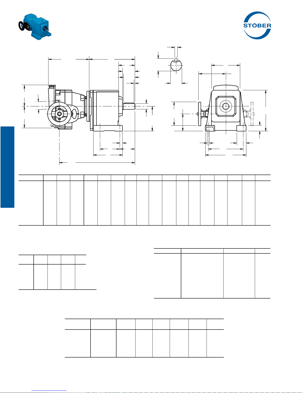
"C" Series – MGS® Adjustable Speed Drives
Dimensional Data
UA
Drawing for Units
C002N — C503N
TL
X
Z
E
Y
I
L
O
P
V
UB
T
HL
Q
U
U
H2
DH
H
See Table No. 2
N
S
G
R
B
J
M
F
A
Table No. 1 "C" Series with ComTrac – Foot Mounting Unit Dimensions (Inches) – "N" Housing Style
Base Module A B D F G H J M N O P Q R S T V Z1
C002 5.20 3.74 5.67 4.33 2.44 3.23 .28 1.38 .79 2.24 1.73 .16 2.17 .43 3.62 1.57 —
C102/C103 6.93 4.65 6.97 5.91 2.76 4.02 .35 1.65 .98 2.72 2.13 .16 2.64 .51 4.88 1.97 —
C202/C203 7.87 5.31 7.68 6.69 3.35 4.531) .43 1.97 1.18 3.39 2.56 .16 3.11 .55 5.43 2.36 —
C302/C303 8.46 6.06 8.46 7.28 4.13 5.121) .43 1.97 1.18 3.35 2.56 .16 3.11 .55 5.91 2.36 —
C402/C403 10.04 7.09 9.65 8.66 4.33 5.71 .55 2.36 1.38 4.17 3.39 .16 4.13 .75 6.89 3.15 —
C502/C503 11.42 7.76 11.42 9.65 5.12 6.69 .71 2.76 1.57 4.21 3.39 .16 4.25 .87 7.56 3.15 —
C612/C613 11.81 10.43 12.40 9.65 8.46 7.871) .71 2.95 1.57 6.02 4.17 .20 5.12 .98 6.97 3.94 6.57
C712/C713 14.37 11.22 14.76 11.81 9.25 9.251) .71 3.54 1.97 7.28 5.00 .20 6.42 .98 7.56 4.72 7.91
C812/C813 17.13 14.17 17.72 13.39 11.81 11.42 .87 3.74 2.17 8.58 5.83 .39 7.48 1.14 8.78 5.51 8.70
1)
See Table No. 2. These sizes are not coaxial. H=Output Height, H1=Input Height.
D
Table No. 2 H1 Dimension (Inches)
Base
Module
C203 3.07 – – –
C303 3.66 3.66 – –
C612 – – 7.64 7.64
C613 7.64 7.64 7.64 7.64
C713 – – – –
These sizes are not coaxial.
H=Output Height, H
TD27 TD37 TD47 TD57
1=Input Height.
Table No. 4
"C" Series with ComTrac Dimensions (Inches)
ComTrac NEMA
Part No. C-Flange DH HL TL X Y Z
TD270K050 56C 4.92 5.67 7.87 2.09 5.55 4.41
TD270K140 143/145TC 4.92 5.67 7.87 2.09 5.55 4.41
TD370K140 143/145TC 4.92 5.91 8.50 2.17 5.67 4.37
TD470K180 182/184TC 6.30 6.81 8.94 2.80 7.20 5.59
TD570K180 182/184TC 7.87 8.31 11.89 3.11 8.11 6.30
34 STOBER Drives Inc. • ComTrac2012 • www.stober.com
Table No. 3 "C" Series Shaft Dimensions (Inches)
Base Module U Tolerance UA – Key UB
C002 .7500 +.0000/-.0006
C102/C103 1.0000 +.0000/-.0006
C202/C203 1.2500 +.0000/-.0007
C302/C303 1.2500 +.0000/-.0007
C402/C403 1.6250 +.0000/-.0007
C502/C503 1.6250 +.0000/-.0007
C612/C613 2.1250 +.0000/-.0008
C712/C713 2.3750 +.0000/-.0008
C812/C813 2.8750 +.0000/-.0008
3
/16 × 3/16 × 17/32 .83
1
/4 × 1/4 × 19/16 1.11
1
/4 × 1/4 × 115/16 1.36
1
/4 × 1/4 × 115/16 1.36
3
3
3
/8 × 3/8 × 27/8 1.79
/8 × 3/8 × 27/8 1.79
1
/2 × 1/2 × 35/32 2.35
5
/8 × 5/8 × 315/16 2.65
/4 × 3/4 × 45/16 3.21
Page 37
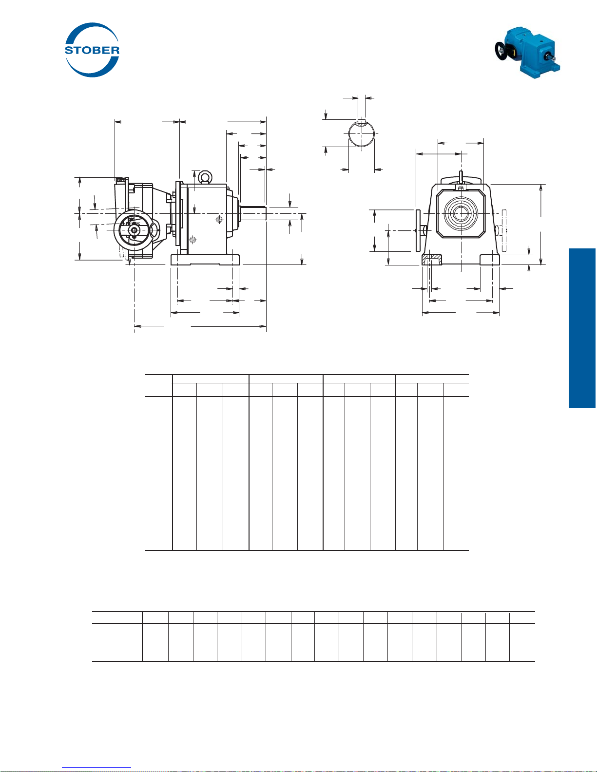
"C" Series – MGS® Adjustable Speed Drives
Dimensional Data
UA
Drawing for Units
C612N — C813N
TL
X
Z
E
Y
I
L
O
P
V
Q
UB
T
HL
U
U
Z
1
H2
DH
H
D
N
See Table No. 2
S
G
R
B
J
M
F
A
Table No. 5 "C" Series with ComTrac – Foot Mounting Unit Dimensions
(Inches) – "N" Housing Style
Base TD270K050
Module H2 I L H2 I L H2 I L H2 I L
C002 1.65 12.40 6.22 1.18 13.07 6.22 — — — — — —
C102 2.44 13.70 7.52 1.97 14.37 7.52 1.42 14.49 7.60 — — —
C202 2.95 14.80 8.62 2.48 15.47 8.62 1.93 15.59 8.70 1.18 18.23 8.70
(1)
C203
1.50 16.50 10.31 — — — — — — — — —
C302 3.54 15.55 9.37 3.07 16.22 9.37 2.52 16.34 9.45 1.77 18.98 9.45
(1)
C303
2.09 17.24 11.06 1.61 17.91 11.06 — — — — — —
C402 4.13 17.44 11.24 3.66 18.11 11.26 3.11 18.23 11.34 2.36 20.87 11.34
C403 4.13 19.13 12.95 3.66 19.80 12.95 — — — — — —
C502 — — — 4.65 18.94 12.09 4.09 19.06 12.17 3.35 21.69 12.17
C503 5.12 19.96 13.78 4.65 20.63 13.78 — — — — — —
(1)
C612
— — — — — — 5.04 20.00 13.11 4.29 22.64 13.11
(1)
C613
6.06 20.94 14.76 5.59 21.61 14.76 5.04 22.44 15.55 4.29 25.08 15.55
C712 — — — — — — 6.65 22.09 15.20 5.91 24.72 15.20
(1)
C713
— — — — — — 6.65 24.49 17.60 5.91 27.13 17.60
C812 — — — — — — — — — — — —
C813 — — — — — — 8.82 27.13 20.24 8.07 29.76 20.24
(1)
See Table No. 2. These sizes are not coaxial. H=Output Height, H1=Input Height.
(2)
Also TD270FK140 for a NEMA 143TC frame motor.
(2)
TD370K140 TD470K180 TD570K180
Table No. 6 "C" Series with ComTrac – Approximate Weight (lbs.)
Part Number C002 C102 C202 C203 C302 C303 C402 C403 C502 C503 C612 C613 C712 C713 C812 C813
TD270K050
TD370K140 69 80 89 — 100 107 122 129 146 162 — 210 — — — —
TD470K180 — 88 97 — 108 — 130 — 154 — 174 218 258 280 — 401
TD570K180 — — 126 — 137 — 159 — 183 — 203 247 287 309 — 430
(2)
Also TD270FK140 for a NEMA 143TC frame motor.
STOBER Drives Inc. • ComTrac2012 • www.stober.com 35
(2)
51 62 71 78 82 89 104 111 128 144 — 148 — — — —
Part No. Example
Foot Mounting with ComTrac, 56C Input, .75 HP motor
C302N0620 TD270K050-075
Page 38
The STOBER Difference . . . .
. . .equals VALUE for you
Additional Product Offering
• MGS® Speed Reducers
• Food and Beverage Duty Speed Reducers
• Poultry Duty Speed Reducers
• ServoFit
• ServoFit
36 STOBER Drives Inc. • ComTrac2012 • www.stober.com
®
Precision Planetary Gearheads
®
Modular System Gearheads
Page 39
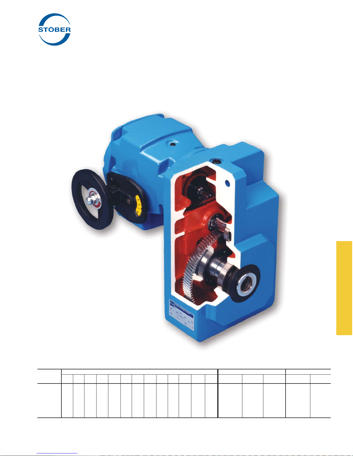
"F" Series – Offset Helical
®
MGS
Adjustable Speed Drives
Performance Specifi cations:
• Horsepower ratings – from 1/2 to 5
• Output speeds – available from 528 to .6 RPM
• Speed range – 5:1 to 7:1
• Output torques – up to 9,744 in.lbs.
• NEMA frames – from 56C to 215TC
STOBER's versatility continues with MGS Reducers and
ComTrac Adjustable Speed Drives when using the Offset Helical
Series.
Compact size and fl exibility make these gear drives a popular
choice for applications that require high performance, effi ciency,
and durability.
Table No. 1 "F" Series – Output Diameter Options
Base Stainless Bushing Bores Sizes – inches Hollow Shaft
Module
F102 x — — — — — — — — — — — — .750 – 20 1.000 25
F202/F203 — x x — — — — — — — — — — 1.000 1.000 25 1.250 30
F302/F303 — x x x x x x — — — — — — 1.250 1.250 30 1.375 35
F402/F403 — x x x x x x — — — — — — 1.500 – 40 1.625 40
F602/F603 — — x — — x x x x x x x x 2.000 – 50 2.125 50
(1)
Contact STOBER Drives for availability.
STOBER Drives Inc. • ComTrac2012 • www.stober.com 37
3
/4 1 13/16 11/4 13/8 17/16 11/2 15/8 111/16 13/4 17/8 115/16 2 Standard Stainless Metric
(1)
Standard Metric
(1)
Page 40
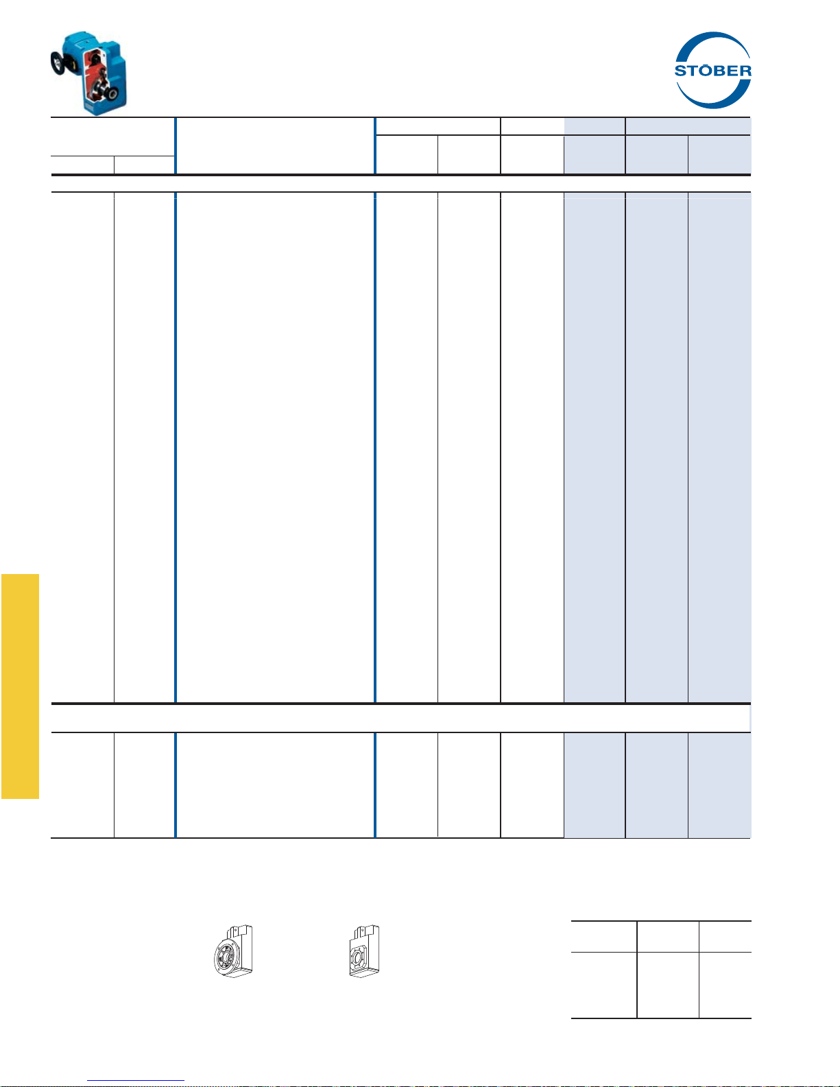
"F" Series – MGS Adjustable Speed Drive
Selection Data
Speed Range Maximum Transition
Output RPM
(1)
Part Number Torque Torque Torque
(2)
Minimum
Max. Min. RPM in.lbs. RPM in.lbs. RPM in.lbs.
.50 HP, 1750 RPM Motor
528 75 F102_0043 TD270K 050-050 528 48 75 278 75 278
486 69
352 50
318 45
254 36
253 36
208 30
167 24
123 18
99 14
81 12
65 9.3
49 7.0
48 6.9
41 5.8
40 5.8
40 5.7
32 4.6
32 4.6
24 3.5
24 3.5
20 2.9
20 2.9
16 2.3
12 1.8
13 1.8
13 1.8
11 1.5
11 1.5
10 1.5
8 1.2
8 1.2
8 1.2
6 0.9
6 0.9
5 0.7
5 0.7
4 0.6
F202_0047 TD270K 050-050 486 53 69 302 69 302
F102_0065 TD270K 050-050 352 73 50 416 50 416
F102_0072 TD270K 050-050 318 81 45 461 45 461
F102_0089 TD270K 050-050 254 101 36 577 36 577
F202_0090 TD270K 050-050 253 101 36 580 36 580
F102_0110 TD270K 050-050 208 123 30 704 30 704
F102_0135 TD270K 050-050 167 153 24 876 24 876
F102_0185 TD270K 050-050 123 208 21 1,063 18 1,063
F102_0230 TD270K 050-050 99 260 23 1,063 14 1,063
F102_0280 TD270K 050-050 81 317 24 1,063 12 1,063
F102_0350 TD270K 050-050 65 394 25 1,063 9.3 1,063
F102_0460 TD270K 050-050 49 523 25 1,063 7.0 1,063
F202_0470 TD270K 050-050 48 529 11 2,126 6.9 2,126
F102_0560 TD270K 050-050 41 630 25 1,063 5.8 1,063
F302_0560 TD270K 050-050 40 636 5.9 3,543 5.8 3,543
F202_0570 TD270K 050-050 40 638 12 2,126 5.7 2,126
F102_0700 TD270K 050-050 32 788 25 1,063 4.6 1,063
F202_0700 TD270K 050-050 32 789 12 2,126 4.6 2,126
F202_0940 TD270K 050-050 24 1,056 13 2,126 3.5 2,126
F402_0930 TD270K 050-050 24 1,050 3.5 6,015 3.5 6,015
F302_1130 TD270K 050-050 20 1,270 7.4 3,543 2.9 3,543
F402_1120 TD270K 050-050 20 1,264 3.6 6,201 2.9 6,201
F402_1400 TD270K 050-050 16 1,573 3.9 6,201 2.3 6,201
F303_1820 TD270K 050-050 12 2,024 7.5 3,543 1.8 3,543
F403_1820 TD270K 050-050 13 2,013 4.1 6,201 1.8 6,201
F603_1810 TD270K 050-050 13 2,004 2.3 9,744 1.8 9,744
F403_2160 TD270K 050-050 11 2,401 4.2 6,201 1.5 6,201
F603_2150 TD270K 050-050 11 2,390 2.4 9,744 1.5 9,744
F303_2180 TD270K 050-050 10 2,423 7.4 3,543 1.5 3,543
F603_2690 TD270K 050-050 8 2,987 2.6 9,744 1.2 9,744
F303_2720 TD270K 050-050 8 3,018 7.3 3,543 1.2 3,543
F403_2710 TD270K 050-050 8 3,005 4.3 6,201 1.2 6,201
F403_3610 TD270K 050-050 6 4,003 4.3 6,201 0.9 6,201
F603_3610 TD270K 050-050 6 4,003 2.7 9,744 0.9 9,744
F403_4340 TD270K 050-050 5 4,815 4.2 6,201 0.7 6,201
F603_4340 TD270K 050-050 5 4,812 2.7 9,744 0.7 9,744
F603_5400 TD270K 050-050 4 5,994 2.7 9,744 0.6 9,744
.75 HP, 1750 RPM Motor Continued on next page
528 75 F102_0043 TD270K 050-075 528 72 131 278 75 278
486 69
352 50
318 45
254 36
253 36
208 30
167 24
1)
Speed tolerance at rated load is ±3%. At less than rated load, minimum speed may increase 5%.
2)
The ComTrac drive operates at constant horsepower above transition values and at constant torque below transition values. Note shaded area.
Engineering advances may cause slight changes to the information shown.
F – Round Flange G – Tapped Holes
Housing Style "F" is available as Hollow (A) or Solid (V) Output.
38 STOBER Drives Inc. • ComTrac2012 • www.stober.com
F202_0047 TD270K 050-075 486 78 120 302 69 302
F102_0065 TD270K 050-075 352 108 87 416 50 416
F102_0072 TD270K 050-075 318 120 79 461 45 461
F102_0089 TD270K 050-075 254 150 63 577 36 577
F202_0090 TD270K 050-075 253 151 63 580 36 580
F102_0110 TD270K 050-075 208 183 52 704 30 704
F102_0135 TD270K 050-075 167 227 41 876 24 876
Housing Styles
See page 78 for mounting positions.
Output Shaft Diameter and
Hollow Output (inches)
See Page 43 for other options.
Base Output Hollow
Module Shaft Output
F102 1.0000 .7500
F202/F203 1.2500 1.0000
F302/F303 1.3750 1.2500
F402/F403 1.6250 1.5000
F602/F603 2.1250 2.0000
Page 41
"F" Series – MGS Adjustable Speed Drive
Selection Data
Speed Range Maximum Transition
Output RPM
(1)
Part Number Torque Torque Torque
(2)
Minimum
Max. Min. RPM in.lbs. RPM in.lbs. RPM in.lbs.
.75 HP, 1750 RPM Motor Continued on next page
123 18 F102_0185 TD270K 050-075 123 309 35 1,063 18 1,063
99 14
81 12
65 9.3
64 9.2
49 7.0
48 6.9
41 5.8
40 5.8
40 5.7
32 4.6
32 4.6
24 3.5
24 3.5
24 3.5
20 2.9
20 2.9
16 2.3
12 1.8
13 1.8
13 1.8
11 1.5
11 1.5
8.4 1.2
8.4 1.2
6.3 0.9
6.3 0.9
5.2 0.7
4.2 0.6
528 75
486 69
352 50
318 45
254 36
253 36
208 30
167 24
123 18
122 17
99 14
97 14
81 12
81 12
65 9.3
64 9.2
49 7.0
48 6.9
F102_0230 TD270K 050-075 99 386 37 1,063 14 1,063
F102_0280 TD270K 050-075 81 471 37 1,063 12 1,063
F102_0350 TD270K 050-075 65 586 38 1,063 9.3 1,063
F202_0350 TD270K 050-075 64 593 17 2,126 9.2 2,126
F102_0460 TD270K 050-075 49 776 37 1,063 7.0 1,063
F202_0470 TD270K 050-075 48 786 18 2,126 6.9 2,126
F102_0560 TD270K 050-075 41 936 36 1,063 5.8 1,063
F302_0560 TD270K 050-075 40 944 10 3,543 5.8 3,543
F202_0570 TD270K 050-075 40 948 19 2,126 5.7 2,126
F202_0700 TD270K 050-075 32 1,172 19 2,126 4.6 2,126
F302_0700 TD270K 050-075 32 1,176 11 3,543 4.6 3,543
F202_0940 TD270K 050-075 24 1,568 19 2,126 3.5 2,126
F302_0940 TD270K 050-075 24 1,565 11 3,543 3.5 3,543
F402_0930 TD270K 050-075 24 1,560 6.0 6,015 3.5 6,015
F302_1130 TD270K 050-075 20 1,886 11 3,543 2.9 3,543
F402_1120 TD270K 050-075 20 1,877 6.1 6,201 2.9 6,201
F402_1400 TD270K 050-075 16 2,336 6.3 6,201 2.3 6,201
F303_1820 TD270K 050-075 12 3,006 11 3,543 1.8 3,543
F403_1820 TD270K 050-075 13 2,990 6.3 6,201 1.8 6,201
F603_1810 TD270K 050-075 13 2,976 3.8 9,744 1.8 9,744
F403_2160 TD270K 050-075 11 3,565 6.4 6,201 1.5 6,201
F603_2150 TD270K 050-075 11 3,549 3.9 9,744 1.5 9,744
F603_2690 TD270K 050-075 8.4 4,436 4.0 9,744 1.2 9,744
F403_2710 TD270K 050-075 8.4 4,462 6.3 6,201 1.2 6,201
F403_3610 TD270K 050-075 6.3 5,945 6.1 6,201 0.9 6,201
F603_3610 TD270K 050-075 6.3 5,945 4.0 9,744 0.9 9,744
F603_4340 TD270K 050-075 5.2 7,147 4.0 9,744 0.7 9,744
F603_5400 TD270K 050-075 4.2 8,902 3.9 9,744 0.6 9,744
F102_0043 TD270K 140-100 528 98 190 278 75 278
F202_0047 TD270K 140-100 486 107 175 302 69 302
F102_0065 TD270K 140-100 352 147 127 416 50 416
F102_0072 TD270K 140-100 318 163 115 461 45 461
F102_0089 TD270K 140-100 254 204 92 577 36 577
F202_0090 TD270K 140-100 253 205 91 580 36 580
F102_0110 TD270K 140-100 208 249 75 704 30 704
F102_0135 TD270K 140-100 167 310 60 876 24 876
F102_0185 TD270K 140-100 123 421 50 1,063 18 1,063
F202_0185 TD270K 140-100 122 425 44 1,202 17 1,202
F102_0230 TD270K 140-100 99 526 51 1,063 14 1,063
F202_0230 TD270K 140-100 97 534 35 1,510 14 1,510
F102_0280 TD270K 140-100 81 642 51 1,063 12 1,063
F202_0280 TD270K 140-100 81 641 29 1,812 12 1,812
F102_0350 TD270K 140-100 65 799 51 1,063 9.3 1,063
F202_0350 TD270K 140-100 64 808 25 2,126 9.2 2,126
F102_0460 TD270K 140-100 49 1,058 49 1,063 7.0 1,063
F202_0470 TD270K 140-100 48 1,072 26 2,126 6.9 2,126
Selection Procedure:
A. Determine the MGS/ComTrac combination according to the Input
HP of the application and the Output RPM nearest the required
maximum speed.
B. Verify that the output torque will suffi ciently meet the application
requirements.
C. Complete the Part No. per the example by adding "A" or "V" for
the Output Style and the Housing Style letter ("B", F", or "G") as
required. "V" output is only available with the "F" housing style.
STOBER Drives Inc. • ComTrac2012 • www.stober.com 39
Part No. Explanation
F 2 0 2 A F 0620 TD370K140 - 200 W
Washdown, when required
Rated for HP (
Non-geared
Ratio of MGS Unit (
Housing Style –
Hollow Output Style –
No. of Gear Reductions
Generation No.
Unit No.
Fset Helical
Of
F (Output Flange)
A
TD37 ComTrac Unit, 145TC Input
0620 = 62.0:1)
200 = 2.00)
Page 42
"F" Series – MGS Adjustable Speed Drive
Selection Data
Speed Range Maximum Transition
Output RPM
(1)
Part Number Torque Torque Torque
(2)
Minimum
Max. Min. RPM in.lbs. RPM in.lbs. RPM in.lbs.
.75 HP, 1750 RPM Motor Continued
48 6.9 F302_0470 TD270K 140-100 48 1,075 17 3,041 6.9 3,041
40 5.8
40 5.7
32 4.6
32 4.6
24 3.5
24 3.5
20 2.9
20 2.9
16 2.3
16 2.3
13 1.8
13 1.8
11 1.5
11 1.5
8.4 1.2
8.4 1.2
6.3 0.9
5.2 0.7
F302_0560 TD270K 140-100 40 1,287 15 3,543 5.8 3,543
F202_0570 TD270K 140-100 40 1,293 26 2,126 5.7 2,126
F202_0700 TD270K 140-100 32 1,598 25 2,126 4.6 2,126
F302_0700 TD270K 140-100 32 1,603 15 3,543 4.6 3,543
F302_0940 TD270K 140-100 24 2,134 15 3,543 3.5 3,543
F402_0930 TD270K 140-100 24 2,127 8.8 6,015 3.5 6,015
F302_1130 TD270K 140-100 20 2,572 15 3,543 2.9 3,543
F402_1120 TD270K 140-100 20 2,559 8.7 6,201 2.9 6,201
F402_1400 TD270K 140-100 16 3,185 8.8 6,201 2.3 6,201
F602_1400 TD270K 140-100 16 3,185 5.9 9,006 2.3 9,006
F403_1820 TD270K 140-100 13 4,077 8.6 6,201 1.8 6,201
F603_1810 TD270K 140-100 13 4,057 5.4 9,744 1.8 9,744
F403_2160 TD270K 140-100 11 4,861 8.5 6,201 1.5 6,201
F603_2150 TD270K 140-100 11 4,838 5.5 9,744 1.5 9,744
F603_2690 TD270K 140-100 8.4 6,048 5.5 9,744 1.2 9,744
F403_2710 TD270K 140-100 8.4 6,084 8.3 6,201 1.2 6,201
F603_3610 TD270K 140-100 6.3 8,105 5.4 9,744 0.9 9,744
F603_4340 TD270K 140-100 5.2 9,744 5.2 9,744 0.7 9,744
1.0 HP, 1750 RPM Motor Continued on next page
508 102 F102_0043 TD370K 140-150 508 152 194 407 102 407
471 94
467 93
394 79
339 68
306 61
244 49
243 49
200 40
202 40
161 32
161 32
119 24
117 23
117 23
95 19
93 19
93 19
78 16
77 15
62 12
62 12
46 9.3
46 9.3
39 7.7
39 7.8
39 7.7
1)
Speed tolerance at rated load is ±3%. At less than rated load, minimum speed may increase 5%.
2)
The ComTrac drive operates at constant horsepower above transition values and at constant torque below transition values. Note shaded area.
Engineering advances may cause slight changes to the information shown.
F – Round Flange G – Tapped Holes
Housing Style "F" is available as Hollow (A) or Solid (V) Output.
F302_0046 TD370K 140-150 471 163 180 439 94 439
F202_0047 TD370K 140-150 467 165 179 442 93 442
F202_0056 TD370K 140-150 394 195 151 525 79 525
F102_0065 TD370K 140-150 339 227 129 611 68 611
F102_0072 TD370K 140-150 306 252 117 676 61 676
F102_0089 TD370K 140-150 244 315 93 846 49 846
F202_0090 TD370K 140-150 243 317 93 851 49 851
F102_0110 TD370K 140-150 200 384 83 956 40 956
F202_0110 TD370K 140-150 202 380 77 1,021 40 1,021
F102_0135 TD370K 140-150 161 478 85 950 32 950
F202_0135 TD370K 140-150 161 479 61 1,288 32 1,288
F102_0185 TD370K 140-150 119 649 84 952 24 952
F202_0185 TD370K 140-150 117 656 45 1,763 23 1,763
F302_0190 TD370K 140-150 117 660 45 1,774 23 1,774
F102_0230 TD370K 140-150 95 812 82 962 19 962
F202_0230 TD370K 140-150 93 824 37 2,126 19 2,126
F302_0240 TD370K 140-150 93 827 36 2,223 19 2,223
F202_0280 TD370K 140-150 78 989 38 2,126 16 2,126
F302_0280 TD370K 140-150 77 993 30 2,668 15 2,668
F202_0350 TD370K 140-150 62 1,247 38 2,126 12 2,126
F302_0350 TD370K 140-150 62 1,233 24 3,311 12 3,311
F202_0470 TD370K 140-150 46 1,655 37 2,126 9.3 2,126
F302_0470 TD370K 140-150 46 1,660 23 3,543 9.3 3,543
F302_0560 TD370K 140-150 39 1,987 23 3,543 7.7 3,543
F402_0560 TD370K 140-150 39 1,969 15 5,290 7.8 5,290
F202_0570 TD370K 140-150 39 1,996 37 2,126 7.7 2,126
Output Shaft Diameter and
Housing Styles
Hollow Output (inches)
See Page 43 for other options.
Base Output Hollow
Module Shaft Output
F102 1.0000 .7500
F202/F203 1.2500 1.0000
See page 78 for mounting positions.
F302/F303 1.3750 1.2500
F402/F403 1.6250 1.5000
F602/F603 2.1250 2.0000
40 STOBER Drives Inc. • ComTrac2012 • www.stober.com
Page 43
"F" Series – MGS Adjustable Speed Drive
Selection Data
Speed Range Maximum Transition
Output RPM
(1)
Part Number Torque Torque Torque
(2)
Minimum
Max. Min. RPM in.lbs. RPM in.lbs. RPM in.lbs.
1.0 HP, 1750 RPM Motor Continued
31 6.2 F302_0700 TD370K 140-150 31 2,475 23 3,543 6.2 3,543
31 6.2
23 4.7
23 4.7
23 4.7
19 3.9
19 3.9
16 3.1
12 2.4
10 2.0
8.1 1.6
F402_0700 TD370K 140-150 31 2,465 13 6,201 6.2 6,201
F402_0930 TD370K 140-150 23 3,283 13 6,201 4.7 6,201
F602_0930 TD370K 140-150 23 3,283 9.0 8,821 4.7 8,821
F302_0940 TD370K 140-150 23 3,294 22 3,543 4.7 3,543
F402_1120 TD370K 140-150 19 3,950 13 6,201 3.9 6,201
F602_1120 TD370K 140-150 19 3,947 8.2 9,744 3.9 9,744
F602_1400 TD370K 140-150 16 4,916 8.3 9,744 3.1 9,744
F603_1810 TD370K 140-150 12 6,263 8.2 9,744 2.4 9,744
F603_2150 TD370K 140-150 10 7,469 8.0 9,744 2.0 9,744
F603_2690 TD370K 140-150 8.1 9,337 7.8 9,744 1.6 9,744
2.0 HP, 1750 RPM Motor
508 102 F102_0043 TD370K 140-200 508 207 271 407 102 407
471 94
467 93
394 79
339 68
306 61
305 61
244 49
243 49
200 40
202 40
161 32
161 32
117 23
117 23
93 19
93 19
78 16
77 15
62 12
62 12
46 9.3
47 9.3
39 7.7
39 7.8
31 6.2
31 6.2
31 6.3
23 4.7
23 4.7
19 3.9
19 3.9
16 3.1
12 2.4
F302_0046 TD370K 140-200 471 223 251 439 94 439
F202_0047 TD370K 140-200 467 225 249 442 93 442
F202_0056 TD370K 140-200 394 267 210 525 79 525
F102_0065 TD370K 140-200 339 310 180 611 68 611
F102_0072 TD370K 140-200 306 344 163 676 61 676
F202_0072 TD370K 140-200 305 344 163 677 61 677
F102_0089 TD370K 140-200 244 430 136 812 49 812
F202_0090 TD370K 140-200 243 432 129 851 49 851
F102_0110 TD370K 140-200 200 524 136 813 40 813
F202_0110 TD370K 140-200 202 519 108 1,021 40 1,021
F102_0135 TD370K 140-200 161 653 132 821 32 821
F202_0135 TD370K 140-200 161 654 86 1,288 32 1,288
F202_0185 TD370K 140-200 117 896 63 1,763 23 1,763
F302_0190 TD370K 140-200 117 902 62 1,774 23 1,774
F202_0230 TD370K 140-200 93 1,125 52 2,126 19 2,126
F302_0240 TD370K 140-200 93 1,129 50 2,223 19 2,223
F202_0280 TD370K 140-200 78 1,350 52 2,126 16 2,126
F302_0280 TD370K 140-200 77 1,356 41 2,668 15 2,668
F202_0350 TD370K 140-200 62 1,703 51 2,126 12 2,126
F302_0350 TD370K 140-200 62 1,682 33 3,311 12 3,311
F302_0470 TD370K 140-200 46 2,266 31 3,543 9.3 3,543
F402_0470 TD370K 140-200 47 2,254 25 4,437 9.3 4,437
F302_0560 TD370K 140-200 39 2,713 31 3,543 7.7 3,543
F402_0560 TD370K 140-200 39 2,688 21 5,290 7.8 5,290
F302_0700 TD370K 140-200 31 3,379 30 3,543 6.2 3,543
F402_0700 TD370K 140-200 31 3,364 18 6,201 6.2 6,201
F602_0700 TD370K 140-200 31 3,344 17 6,582 6.3 6,582
F402_0930 TD370K 140-200 23 4,482 18 6,201 4.7 6,201
F602_0930 TD370K 140-200 23 4,482 12 8,821 4.7 8,821
F402_1120 TD370K 140-200 19 5,391 17 6,201 3.9 6,201
F602_1120 TD370K 140-200 19 5,388 11 9,744 3.9 9,744
F602_1400 TD370K 140-200 16 6,711 11 9,744 3.1 9,744
F603_1810 TD370K 140-200 12 8,550 11 9,744 2.4 9,744
Selection Procedure:
A. Determine the MGS/ComTrac combination according to the Input
HP of the application and the Output RPM nearest the required
maximum speed.
B. Verify that the output torque will suffi ciently meet the application
requirements.
C. Complete the Part No. per the example by adding "A" or "V" for
the Output Style and the Housing Style letter ("B", F", or "G") as
required. "V" output is only available with the "F" housing style.
STOBER Drives Inc. • ComTrac2012 • www.stober.com 41
Part No. Explanation
F 2 0 2 A F 0620 TD370K140 - 200 W
Washdown, when required
Rated for HP (
Non-geared
Ratio of MGS Unit (
Housing Style –
Hollow Output Style –
No. of Gear Reductions
Generation No.
Unit No.
Fset Helical
Of
F (Output Flange)
A
TD37 ComTrac Unit, 145TC Input
0620 = 62.0:1)
200 = 2.00)
Page 44
"F" Series – MGS Adjustable Speed Drive
Selection Data
Speed Range Maximum Transition
Output RPM
(1)
Part Number Torque Torque Torque
(2)
Minimum
Max. Min. RPM in.lbs. RPM in.lbs. RPM in.lbs.
3.0 HP, 1750 RPM Motor
471 94 F302_0046 TD470K 180-300 471 344 204 798 94 798
467 93
394 79
382 76
376 75
305 61
243 49
243 49
202 40
203 41
161 32
163 33
117 23
117 23
117 23
93 19
94 19
93 19
77 15
78 16
62 12
62 12
46 9.3
47 9.3
47 9.4
39 7.8
39 7.9
31 6.2
31 6.3
23 4.7
F202_0047 TD470K 180-300 467 347 203 804 93 804
F202_0056 TD470K 180-300 394 412 171 954 79 954
F302_0057 TD470K 180-300 382 424 166 983 76 983
F402_0058 TD470K 180-300 376 431 163 999 75 999
F202_0072 TD470K 180-300 305 531 132 1,232 61 1,232
F202_0090 TD470K 180-300 243 668 105 1,548 49 1,548
F302_0090 TD470K 180-300 243 666 106 1,544 49 1,544
F202_0110 TD470K 180-300 202 801 88 1,856 40 1,856
F302_0110 TD470K 180-300 203 800 88 1,853 41 1,853
F202_0135 TD470K 180-300 161 1,010 89 1,860 32 1,860
F302_0135 TD470K 180-300 163 992 71 2,300 33 2,300
F202_0185 TD470K 180-300 117 1,383 90 1,853 23 1,853
F402_0185 TD470K 180-300 117 1,381 51 3,200 23 3,200
F302_0190 TD470K 180-300 117 1,392 51 3,226 23 3,226
F202_0230 TD470K 180-300 93 1,738 88 1,872 19 1,872
F402_0230 TD470K 180-300 94 1,721 41 3,989 19 3,989
F302_0240 TD470K 180-300 93 1,744 46 3,543 19 3,543
F302_0280 TD470K 180-300 77 2,093 47 3,543 15 3,543
F402_0280 TD470K 180-300 78 2,075 34 4,809 16 4,809
F302_0350 TD470K 180-300 62 2,598 47 3,543 12 3,543
F402_0350 TD470K 180-300 62 2,601 27 6,028 12 6,028
F302_0470 TD470K 180-300 46 3,499 46 3,543 9.3 3,543
F402_0470 TD470K 180-300 47 3,481 27 6,201 9.3 6,201
F602_0470 TD470K 180-300 47 3,464 20 8,028 9.4 8,028
F402_0560 TD470K 180-300 39 4,151 27 6,201 7.8 6,201
F602_0560 TD470K 180-300 39 4,131 17 9,574 7.9 9,574
F402_0700 TD470K 180-300 31 5,195 27 6,201 6.2 6,201
F602_0700 TD470K 180-300 31 5,164 17 9,744 6.3 9,744
F602_0930 TD470K 180-300 23 6,921 17 9,744 4.7 9,744
5.0 HP, 1750 RPM Motor Continued on next page
471 94 F302_0046 TD570K 180-500 471 590 235 1,197 94 1,197
467 93
468 94
394 79
382 76
376 75
305 61
305 61
243 49
243 49
244 49
202 40
203 41
202 40
163 33
161 32
1)
Speed tolerance at rated load is ±3%. At less than rated load, minimum speed may increase 5%.
2)
The ComTrac drive operates at constant horsepower above transition values and at constant torque below transition values. Note shaded area.
Engineering advances may cause slight changes to the information shown.
F – Round Flange G – Tapped Holes
Housing Style "F" is available as Hollow (A) or Solid (V) Output.
F202_0047 TD570K 180-500 467 594 233 1,206 93 1,206
F402_0047 TD570K 180-500 468 594 233 1,206 94 1,206
F202_0056 TD570K 180-500 394 705 197 1,429 79 1,429
F302_0057 TD570K 180-500 382 726 191 1,474 76 1,474
F402_0058 TD570K 180-500 376 738 188 1,498 75 1,498
F202_0072 TD570K 180-500 305 910 201 1,419 61 1,419
F302_0072 TD570K 180-500 305 911 152 1,849 61 1,849
F202_0090 TD570K 180-500 243 1,144 199 1,423 49 1,423
F302_0090 TD570K 180-500 243 1,141 121 2,316 49 2,316
F402_0090 TD570K 180-500 244 1,140 121 2,315 49 2,315
F202_0110 TD570K 180-500 202 1,372 195 1,434 40 1,434
F302_0110 TD570K 180-500 203 1,370 101 2,780 41 2,780
F402_0110 TD570K 180-500 202 1,375 101 2,790 40 2,790
F302_0135 TD570K 180-500 163 1,700 93 3,058 33 3,058
F402_0135 TD570K 180-500 161 1,723 80 3,498 32 3,498
Output Shaft Diameter and
Housing Styles
Hollow Output (inches)
See Page 43 for other options.
Base Output Hollow
Module Shaft Output
F102 1.0000 .7500
F202/F203 1.2500 1.0000
See page 78 for mounting positions.
F302/F303 1.3750 1.2500
F402/F403 1.6250 1.5000
F602/F603 2.1250 2.0000
42 STOBER Drives Inc. • ComTrac2012 • www.stober.com
Page 45
"F" Series – MGS Adjustable Speed Drive
Selection Data
Speed Range Maximum Transition
Output RPM
(1)
Part Number Torque Torque Torque
(2)
Minimum
Max. Min. RPM in.lbs. RPM in.lbs. RPM in.lbs.
5.0 HP, 1750 RPM Motor Continued
117 23 F402_0185 TD570K 180-500 117 2,364 59 4,800 23 4,800
117 23
94 19
94 19
93 19
78 16
78 16
62 12
62 12
47 9.3
47 9.4
39 7.9
31 6.3
F302_0190 TD570K 180-500 117 2,384 93 3,054 23 3,054
F402_0230 TD570K 180-500 94 2,948 47 5,984 19 5,984
F602_0230 TD570K 180-500 94 2,955 47 5,999 19 5,999
F302_0240 TD570K 180-500 93 2,987 90 3,082 19 3,082
F402_0280 TD570K 180-500 78 3,554 46 6,201 16 6,201
F602_0280 TD570K 180-500 78 3,554 39 7,214 16 7,214
F402_0350 TD570K 180-500 62 4,455 46 6,201 12 6,201
F602_0350 TD570K 180-500 62 4,471 31 9,075 12 9,075
F402_0470 TD570K 180-500 47 5,961 45 6,201 9.3 6,201
F602_0470 TD570K 180-500 47 5,933 29 9,744 9.4 9,744
F602_0560 TD570K 180-500 39 7,075 29 9,744 7.9 9,744
F602_0700 TD570K 180-500 31 8,844 29 9,744 6.3 9,744
Selection Procedure:
A. Determine the MGS/ComTrac combination according to the Input
HP of the application and the Output RPM nearest the required
maximum speed.
B. Verify that the output torque will suffi ciently meet the application
requirements.
C. Complete the Part No. per the example by adding "A" or "V" for
the Output Style and the Housing Style letter ("B", F", or "G") as
required. "V" output is only available with the "F" housing style.
STOBER Drives Inc. • ComTrac2012 • www.stober.com 43
Part No. Explanation
F 2 0 2 A F 0620 TD370K140 - 200 W
Washdown, when required
Rated for HP (
Non-geared
Ratio of MGS Unit (
Housing Style –
Hollow Output Style –
No. of Gear Reductions
Generation No.
Unit No.
Fset Helical
Of
F (Output Flange)
A
TD37 ComTrac Unit, 145TC Input
0620 = 62.0:1)
200 = 2.00)
Page 46
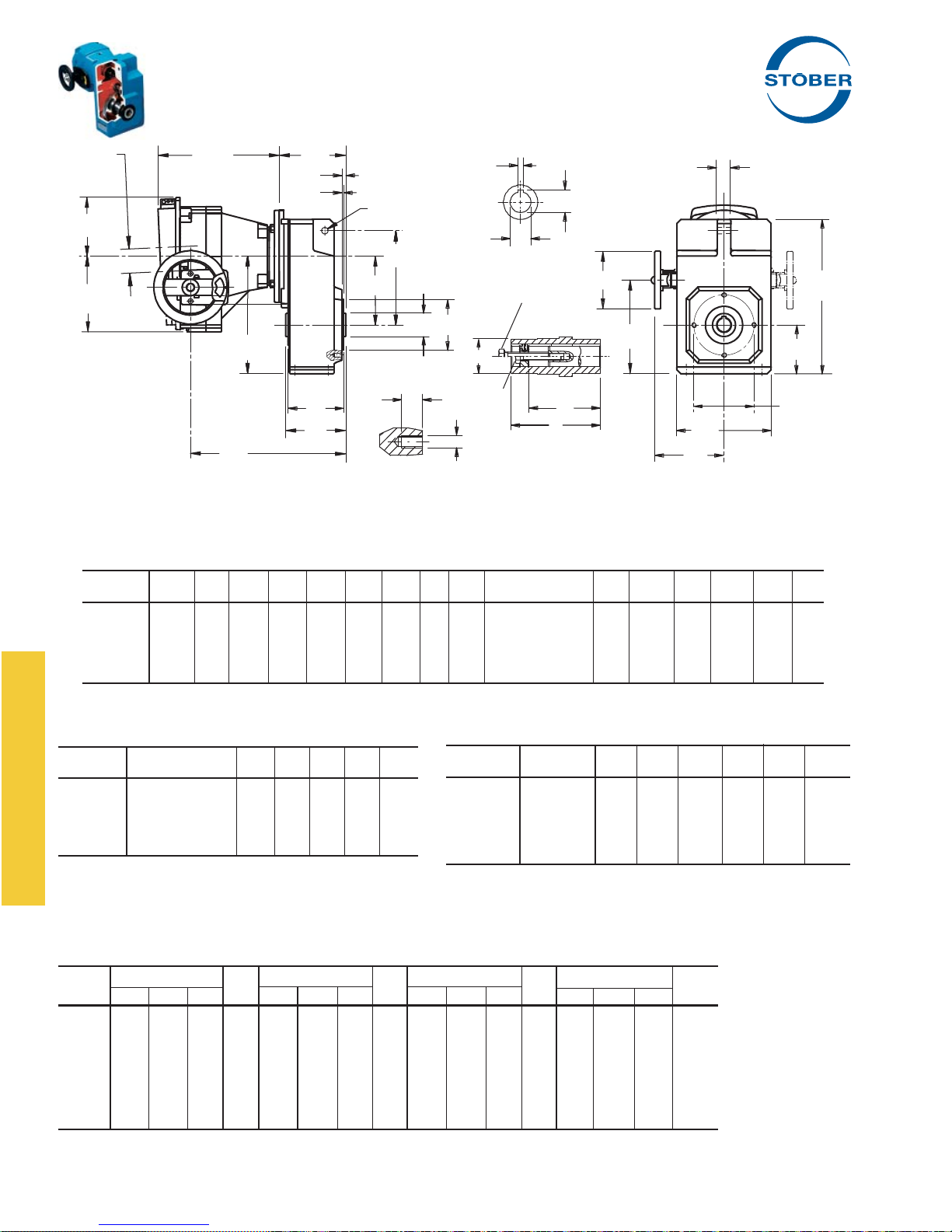
"F" Series – MGS® Adjustable Speed Drives
Dimensional Data
X
TL
Z
L
V
P
J
1
UA
G
UB
U
F
Y
H1
BP
CD
UC
M
UC
DP
1
2
B
I
DH
2
H
UL
B
T
HL
J2*
Drawing for Units
F102AG — F603AG
Part No. Example
Basic Unit with ComTrac
F302AG0620 TD270K140
Table No. 1 "F" Series – Tapped Holes Unit Dimensions (Inches) – "G" Housing Style
Base
Module CD B D F G H H
F102 4.02 3.74 9.37 5.91 .79 2.91 6.93 .43 M8 2.756 +.0007/-.0005 .10 5.71 .26 3.35 3.43 .51
F202/F203 5.16 4.53 11.77 7.13 .87 3.66 8.82 .43 M8 3.740 +.0007/-.0005 .12 7.09 .31 4.53 4.13 .51
F302/F303 5.89 5.12 13.23 8.07 1.18 4.17 10.06 .55 M10 4.331 +.0007/-.0005 .14 8.11 .33 5.12 4.72 .63
F402/F403 6.651) 5.71 14.57 8.98 1.18 4.57 11.22 .55 M10 4.331 +.0007/-.0005 .14 9.06 .33 5.12 5.31 .63
F602/F603 7.72 7.09 17.64 10.63 1.38 5.39 13.11 .87 M10 5.118 +.0008/-.0006 .14 10.43 .41 6.50 6.54 .63
* F602 and F603 has 8 tapped holes instead of 4 as shown on drawing.
1)
"CD" is 5.20 for a F403 with TD27.
1 J1 J2 * M Tolerance P T V BC BP DP
D
H
BC
Table No. 2 "F" Series Bore Dimensions (Inches)
Base
Module U Tolerance UA UB UC UL 1
F102 .750 +.0008/-.0000 .187 .84 1.38 2.87 3/8-16
F202 1.000 +.0008/-.0000 .250 1.12 1.77 3.62 1/2-13
F302 1.250 +.0010/-.0000 .250 1.37 1.97 4.06 1/2-13
F402/F403 1.500 +.0010/-.0000 .375 1.67 2.17 4.49 3/4-10
F602/F603 2.000 +.0012/-.0000 .500 2.23 2.76 5.63 3/4-10
1. Removal Bolt — not supplied.
2. Mounting Bolt — must be smaller than removal bolt.
All weights are approximate.
Table No. 3 "F" Series – Unit Dimensions (Inches)
ComTrac NEMA
Part No. C-Flange DH HL TL X Y Z
TD270K050 56C 4.92 5.67 7.87 2.09 5.55 4.41
TD270K140 143/145TC 4.92 5.67 7.87 2.09 5.55 4.41
TD370K140 143/145TC 4.92 5.91 8.50 2.17 5.67 4.37
TD470K180 182/184TC 6.30 6.81 8.94 2.80 7.20 5.59
TD570K180 182/184TC 7.87 8.31 11.89 3.11 8.11 6.30
Table No. 4 "F" Series – Unit Dimensions (Inches)
Base TD270K050
Module H
F102 5.35 10.43 4.25 71 4.88 11.10 4.25 89 — — — — — — — —
F202 7.24 11.18 5.08 84 6.77 11.85 5.08 102 6.22 11.97 5.08 110 — — — —
F302 8.48 11.77 5.67 100 8.01 12.52 5.67 118 7.46 12.56 5.67 126 6.20 15.20 5.67 155
F402 9.65 12.36 6.38 117 9.17 13.03 6.38 135 8.62 13.15 6.38 143 7.87 15.79 6.38 172
F403 8.19 14.06 7.87 124 — — — — — — — — — — — —
F602 11.54 13.85 7.48 198 11.06 14.33 7.68 216 10.51 14.45 7.68 224 9.76 17.09 7.68 253
F603 11.54 15.35 9.17 210 11.06 16.02 9.17 228 — — — — — — — —
(2)
Also available for a NEMA 143TC frame motor.
2 I L lbs. H2 I L lbs. H2 I L lbs. H2 I L lbs.
(2)
Wt. TD370K140 Wt. TD470K180 Wt. TD570K180 Wt.
44 STOBER Drives Inc. • ComTrac2012 • www.stober.com
Page 47
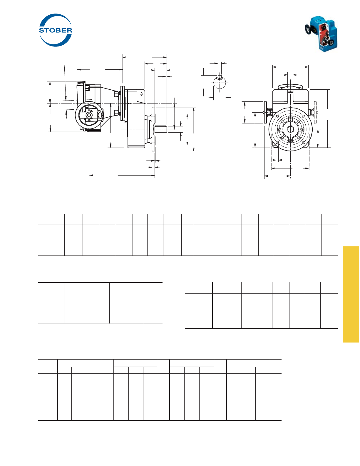
"F" Series – MGS® Adjustable Speed Drives
Dimensional Data
L
X
TL
Z
Y
P
V
Q
UB
CD
U
UA
T
G
U
DH
D
M
H
H1
A
N
O
I
Drawing for Units
F102VF — F603VF
2
H
J
F
HL
Part No. Example
Basic Unit with ComTrac
F302VF0620 TD270K140
Table No. 1 "F" Series – Round Flange Dimensions (Inches) – "F" Housing Style
Base
Module CD A D F G H H
F102 4.02 6.30 9.37 5.12 .79 2.91 6.93 .35 4.331 +.0008/-.0006 .14 .39 3.80 .16 5.71 1.97
F202/F203 5.16 7.87 11.77 6.50 .87 3.66 8.82 .43 5.118 +.0008/-.0006 .14 .55 4.53 .16 7.09 2.36
F302/F303 5.89 9.84 13.23 8.46 1.18 4.17 10.06 .55 7.087 +.0008/-.0006 .16 .59 5.10 .16 8.11 2.76
F402/F403 6.651) 9.84 14.57 8.46 1.18 4.57 11.22 .55 7.087 +.0008/-.0006 .16 .59 5.49 .16 9.06 3.15
F602/F603 7.72 11.81 17.64 10.43 1.38 5.39 13.11 .55 9.055 +.0012/-.0008 .16 .67 6.44 .20 10.43 3.94
1)
"CD" is 5.20 for a F403 with TD27.
1 J M Tolerance N O P Q T V
T able No. 2 "F" Series Shaft Dimensions (Inches)
Base
Module U Tolerance UA – Key UB
F102 1.000 +.0000/-.0006
F202 1.250 +.0000/-.0007
F302 1.375 +.0000/-.0007
F402/F403 1.625 +.0000/-.0007
F602/F603 2.125 +.0000/-.0008
1
/4 × 1/4 × 19/16 1.11
1
/4 × 1/4 × 115/16 1.36
5
/16 × 5/16 × 25/16 1.51
3
/8 × 3/8 × 27/8 1.79
1
/2 × 1/2 × 35/32 2.35
Table No. 3 "F" Series – Unit Dimensions (Inches)
ComTrac NEMA
Part No. C-Flange DH HL TL X Y Z
TD270K050 56C 4.92 5.67 7.87 2.09 5.55 4.41
TD270K140 143/145TC 4.92 5.67 7.87 2.09 5.55 4.41
TD370K140 143/145TC 4.92 5.91 8.50 2.17 5.67 4.37
TD470K180 182/184TC 6.30 6.81 8.94 2.80 7.20 5.59
TD570K180 182/184TC 7.87 8.31 11.89 3.11 8.11 6.30
Table No. 4 "F" Series – Unit Dimensions (Inches)
Base TD270K050
Module H
F102 5.35 11.46 7.24 71 4.88 12.13 7.24 89 — — — — — — — —
F202 7.24 12.44 8.54 84 6.77 13.11 8.54 102 6.22 13.15 8.62 110 — — — —
F302 8.48 13.11 9.61 100 8.01 13.78 9.61 118 7.46 13.81 9.69 126 6.20 16.45 9.69 155
F402 9.65 13.82 10.59 117 9.17 14.49 10.59 135 8.62 14.53 10.67 143 7.87 17.17 10.67 172
F403 8.19 15.31 12.28 124 — — — — — — — — — — — —
F602 11.54 15.03 12.60 198 11.06 15.75 12.60 216 10.51 15.71 12.68 224 9.76 18.39 12.68 253
F603 11.54 15.35 14.29 210 11.06 16.02 14.29 228 — — — — — — — —
(2)
Also available for a NEMA 143TC frame motor.
All weights are approximate.
STOBER Drives Inc. • ComTrac2012 • www.stober.com 45
2 I L lbs. H2 I L lbs. H2 I L lbs. H2 I L lbs.
(2)
Wt. TD370K140 Wt. TD470K180 Wt. TD570K180 Wt.
Page 48
Personalized Mailer
Available Free!
YOUR
LOGO *
HERE
The above mailer provides introductory information on industrial products. The back of this one
page mailer describes the performance data for ComTrac and MGS products.
Contact your STOBER representative for more information or to request a quantity for your
mailing. We will imprint them with your logo and send them to you – free!
* Logo should be in a high resolution tif format for best printing results.
46 STOBER Drives Inc. • ComTrac2012 • www.stober.com
Page 49
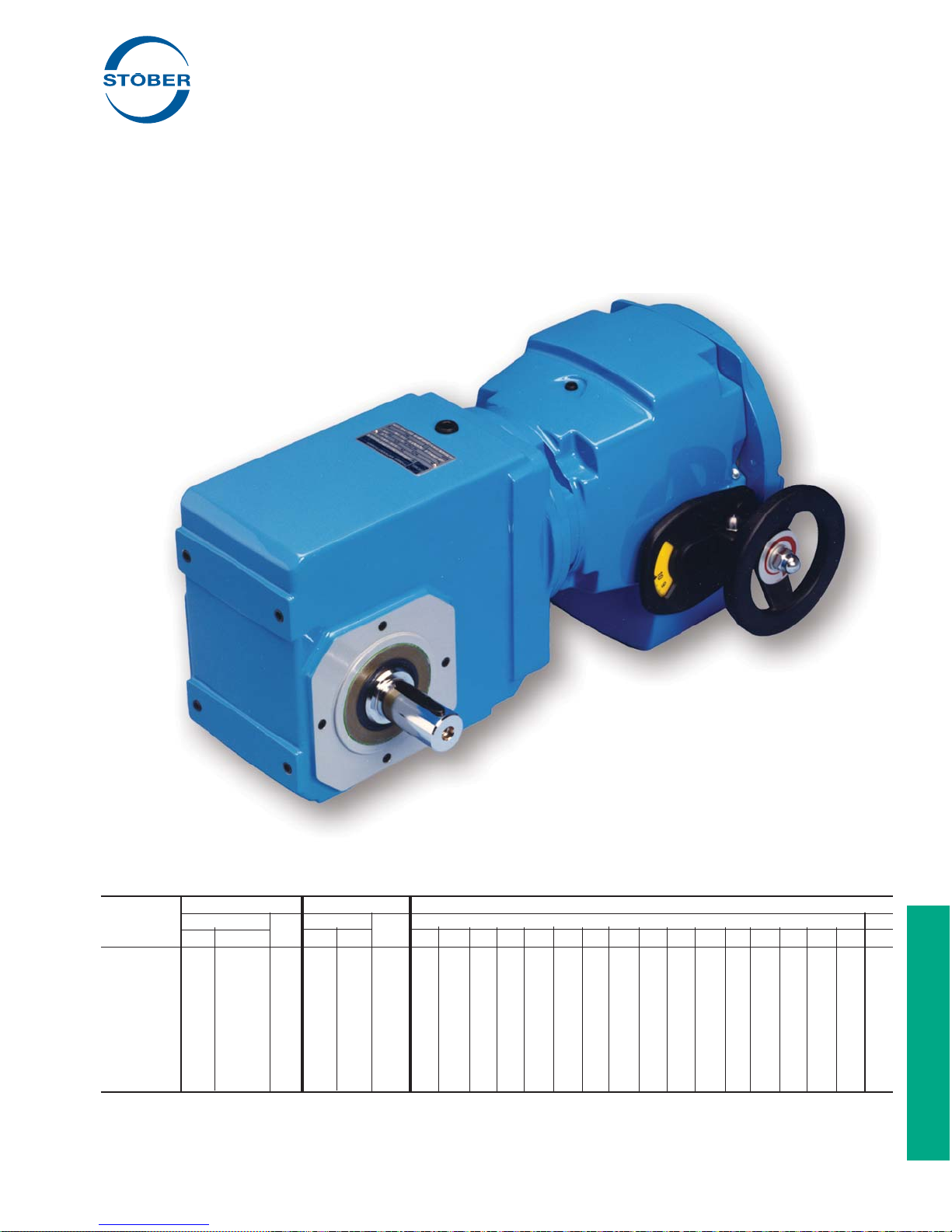
"K" Series – Right Angle Helical/Bevel
MGS
®
Adjustable Speed Drives
Performance Specifi cations:
• Horsepower ratings – from 1/2 to 5
• Output speeds – available from 569 to .9 RPM
• Speed range – 5:1 to 7:1
• Output torques – up to 99,227 in.lbs.
• NEMA frames – from 56C to 215TC
With the many mounting options available, ComTrac Adjustable
Speed Drives and MGS Helical/Bevel Speed Reducers offer
consistent, higher input-to-output effi ciencies and a confi gurations
for almost any application situation. This added effi ciency reduces
your costs today through smaller gear drive and motor sizing.
Tomorrow, you'll benefi t through optimum energy savings.
Table No. 1 "K" Series Output Diameters
Base Hollow Shaft Stainless Steel Bushing Bores
inches mm inches mm inches mm
Module Std SS
K102 1 1 25 1 1 25 x — — — — — — — — — — — — — — — —
K202/K203 13/16 11/4 30 11/4 11/4 30 x x — — — — — — — — — — — — — — —
K302/K303 13/8 11/4 & 13/8 30 11/4 11/4 30 x x x x x x — — — — — — — — — — —
K402/K403 11/2 — 40 13/8 13/8 40 x x x x x x — — — — — — — — — — x
K513/K514 2 — 50 13/4 13/4 45 — — — — x x x x x x x x — — — — x
K613/K614 2 — 50 13/4 13/4 50 — — — — x x x x x — x x x — — — x
K713/K714 23/8 — 60 23/8 23/8 60 — — — — — — — — — — x x x x — — —
K813/K814 23/4 — 70 27/8 27/8 70 — — — — — — — — — — — — x x x x —
K913/K914 31/4 — 90 35/8 — 90 — — — — — — — — — — — — — — — — —
(1)
Contact STOBER Drives for availability.
(2
"K" Series stainless steel shaft are single side ONLY.
STOBER Drives Inc. • ComTrac2012 • www.stober.com 47
(1)
Std SS
(2) (1)
1 13/16 11/4 13/8 17/16 11/2 15/8 111/16 13/4 17/8 115/16 2 23/16 23/8 27/16 23/4 40
Page 50
"K" Series – MGS Adjustable Speed Drive
Selection Data
Speed Range Maximum Transition
Output RPM
(1)
Part Number Torque Torque Torque
(2)
Minimum
Max. Min. RPM in.lbs. RPM in.lbs. RPM in.lbs.
.50 HP, 1750 RPM Motor Continued on next page
569 81 K102_0040 TD270K 050-050 569 45 81 258 81 258
521 74
409 58
379 54
342 49
340 49
274 39
271 39
246 35
224 32
197 28
180 26
161 23
136 19
135 19
130 19
113 16
98 14
90 13
81 12
70 10
70 10
68 10
65 9.3
63 9.1
58 8.3
56 8.0
51 7.2
49 7.0
47 6.7
45 6.4
46 6.6
42 6.0
41 5.8
35 5.0
34 4.9
33 4.7
32 4.6
29 4.1
27 3.8
27 3.9
26 3.7
25 3.6
24 3.5
25 3.5
24 3.4
21 3.0
21 3.0
1)
Speed tolerance at rated load is ±3%. At less than rated load, minimum speed may increase 5%.
2)
The ComTrac drive operates at constant horsepower above transition values and at constant torque below transition values. Note shaded area.
Engineering advances may cause slight changes to the information shown.
N – Foot Mounted F – Round Flange G – Tapped Holes
These Housing Styles are available as Hollow (A) or Solid (V) Output.
See page 79 for mounting positions.
K202_0044 TD270K 050-050 521 49 74 281 74 281
K102_0056 TD270K 050-050 409 63 58 359 58 359
K102_0060 TD270K 050-050 379 68 54 387 54 387
K102_0066 TD270K 050-050 342 75 49 428 49 428
K202_0067 TD270K 050-050 340 75 49 431 49 431
K102_0083 TD270K 050-050 274 94 39 535 39 535
K202_0084 TD270K 050-050 271 95 39 541 39 541
K102_0092 TD270K 050-050 246 104 35 596 35 596
K102_0100 TD270K 050-050 224 114 32 653 32 653
K102_0115 TD270K 050-050 197 130 28 745 28 745
K102_0125 TD270K 050-050 180 142 26 813 26 813
K102_0140 TD270K 050-050 161 159 23 910 23 910
K102_0165 TD270K 050-050 136 188 23 974 19 974
K202_0170 TD270K 050-050 135 190 19 1,086 19 1,086
K102_0175 TD270K 050-050 130 198 20 1,063 19 1,063
K102_0200 TD270K 050-050 113 227 24 974 16 974
K102_0230 TD270K 050-050 98 262 23 1,063 14 1,063
K102_0250 TD270K 050-050 90 284 30 851 13 851
K102_0280 TD270K 050-050 81 316 24 1,063 12 1,063
K403_0320 TD270K 050-050 70 359 10 2,057 10 2,057
K303_0330 TD270K 050-050 70 362 10 2,074 10 2,074
K202_0340 TD270K 050-050 68 378 18 1,364 10 1,364
K102_0350 TD270K 050-050 65 395 25 1,063 9.3 1,063
K303_0360 TD270K 050-050 63 397 9.1 2,276 9.1 2,276
K303_0390 TD270K 050-050 58 435 8.3 2,489 8.3 2,489
K302_0410 TD270K 050-050 56 456 14 1,705 8.0 1,705
K303_0450 TD270K 050-050 51 498 7.2 2,851 7.2 2,851
K202_0460 TD270K 050-050 49 520 14 1,772 7.0 1,772
K303_0490 TD270K 050-050 47 539 6.7 3,089 6.7 3,089
K402_0500 TD270K 050-050 45 568 10 2,387 6.4 2,387
K403_0490 TD270K 050-050 46 543 6.6 3,109 6.6 3,109
K303_0540 TD270K 050-050 42 598 7.0 3,100 6.0 3,100
K302_0560 TD270K 050-050 41 627 11 2,345 5.8 2,345
K303_0650 TD270K 050-050 35 727 7.5 3,100 5.0 3,100
K303_0670 TD270K 050-050 34 742 7.6 3,100 4.9 3,100
K402_0690 TD270K 050-050 33 780 7.3 3,283 4.7 3,283
K513_0700 TD270K 050-050 32 777 4.6 4,451 4.6 4,451
K303_0780 TD270K 050-050 29 870 7.9 3,100 4.1 3,100
K514_0850 TD270K 050-050 27 928 3.8 5,316 3.8 5,316
K614_0840 TD270K 050-050 27 915 3.9 5,241 3.9 5,241
K513_0870 TD270K 050-050 26 968 3.7 5,544 3.7 5,544
K303_0900 TD270K 050-050 25 999 8.2 3,100 3.6 3,100
K514_0940 TD270K 050-050 24 1,028 3.5 5,886 3.5 5,886
K614_0930 TD270K 050-050 25 1,014 3.5 5,803 3.5 5,803
K513_0970 TD270K 050-050 24 1,072 3.4 6,138 3.4 6,138
K303_1080 TD270K 050-050 21 1,196 8.4 3,100 3.0 3,100
K403_1070 TD270K 050-050 21 1,191 4.9 4,872 3.0 4,872
Housing Styles
Output Shaft Diameter and Hollow Output (inches)
See Page 53 for other options.
Base Output Hollow Base Output Hollow
Module Shaft Output Module Shaft Output
K102 1.000 1.000 K613/K614 1.750 2.000
K202/K203 1.250 1.187 K713/K714 2.375 2.375
K302/K303 1.250 1.375 K813/K814 2.875 2.750
K402/K403 1.375 1.500 K913/K914 3.625 3.250
K513/K514 1.750 2.000
48 STOBER Drives Inc. • ComTrac2012 • www.stober.com
Page 51
"K" Series – MGS Adjustable Speed Drive
Selection Data
Speed Range Maximum Transition
Output RPM
(1)
Part Number Torque Torque Torque
(2)
Minimum
Max. Min. RPM in.lbs. RPM in.lbs. RPM in.lbs.
.50 HP, 1750 RPM Motor Continued
20 2.9 K514_1130 TD270K 050-050 20 1,232 2.9 7,054 2.9 7,054
20 2.9
20 2.9
18 2.6
18 2.6
18 2.6
17 2.4
17 2.4
17 2.4
17 2.4
15 2.2
15 2.2
15 2.1
14 1.9
14 2.0
13 1.8
13 1.8
13 1.9
12 1.7
12 1.8
12 1.7
11 1.5
10 1.4
10 1.5
10 1.4
9.2 1.3
9.1 1.3
9.1 1.3
8.6 1.2
8.4 1.2
8.3 1.2
7.7 1.1
7.6 1.1
7.5 1.1
6.8 1.0
6.7 1.0
6.6 0.9
6.2 0.9
6.1 0.9
6.0 0.9
K614_1110 TD270K 050-050 20 1,215 2.9 6,955 2.9 6,955
K714_1130 TD270K 050-050 20 1,236 2.9 7,079 2.9 7,079
K514_1250 TD270K 050-050 18 1,364 2.6 7,810 2.6 7,810
K614_1230 TD270K 050-050 18 1,345 2.6 7,700 2.6 7,700
K714_1250 TD270K 050-050 18 1,369 2.6 7,837 2.6 7,837
K303_1340 TD270K 050-050 17 1,490 8.5 3,100 2.4 3,100
K514_1350 TD270K 050-050 17 1,469 2.6 7,972 2.4 7,972
K614_1340 TD270K 050-050 17 1,461 2.4 8,366 2.4 8,366
K714_1370 TD270K 050-050 17 1,496 2.4 8,566 2.4 8,566
K514_1490 TD270K 050-050 15 1,627 2.7 7,972 2.2 7,972
K614_1480 TD270K 050-050 15 1,618 2.2 9,263 2.2 9,263
K714_1520 TD270K 050-050 15 1,656 2.1 9,484 2.1 9,484
K514_1680 TD270K 050-050 14 1,836 2.9 7,972 1.9 7,972
K614_1670 TD270K 050-050 14 1,820 2.0 10,421 2.0 10,421
K303_1790 TD270K 050-050 13 1,983 8.7 3,048 1.8 3,048
K403_1790 TD270K 050-050 13 1,986 5.5 4,737 1.8 4,737
K714_1740 TD270K 050-050 13 1,902 1.9 10,891 1.9 10,891
K514_1860 TD270K 050-050 12 2,033 3.0 7,972 1.7 7,972
K614_1850 TD270K 050-050 12 2,015 1.8 11,537 1.8 11,537
K714_1930 TD270K 050-050 12 2,106 1.7 12,058 1.7 12,058
K403_2150 TD270K 050-050 11 2,389 7.1 3,752 1.5 3,752
K514_2250 TD270K 050-050 10 2,461 3.1 7,972 1.4 7,972
K614_2230 TD270K 050-050 10 2,429 1.6 12,844 1.5 12,844
K714_2260 TD270K 050-050 10 2,473 1.4 14,158 1.4 14,158
K614_2460 TD270K 050-050 9.2 2,690 1.7 12,844 1.3 12,844
K514_2500 TD270K 050-050 9.1 2,725 3.2 7,972 1.3 7,972
K714_2510 TD270K 050-050 9.1 2,738 1.3 15,675 1.3 15,675
K614_2660 TD270K 050-050 8.6 2,903 2.0 11,639 1.2 11,639
K514_2710 TD270K 050-050 8.4 2,959 3.5 7,268 1.2 7,268
K714_2750 TD270K 050-050 8.3 3,006 1.2 17,212 1.2 17,212
K614_2940 TD270K 050-050 7.7 3,214 1.8 12,844 1.1 12,844
K514_3000 TD270K 050-050 7.6 3,276 3.2 7,972 1.1 7,972
K714_3050 TD270K 050-050 7.5 3,328 1.1 19,056 1.1 19,056
K614_3330 TD270K 050-050 6.8 3,638 3.0 8,600 1.0 8,600
K514_3380 TD270K 050-050 6.7 3,685 4.3 6,105 1.0 6,105
K714_3440 TD270K 050-050 6.6 3,758 1.6 14,803 0.9 14,803
K614_3690 TD270K 050-050 6.2 4,028 2.7 9,524 0.9 9,524
K514_3740 TD270K 050-050 6.1 4,080 3.9 6,761 0.9 6,761
K714_3810 TD270K 050-050 6.0 4,160 1.4 16,394 0.9 16,394
Selection Procedure:
A. Determine the MGS/ComTrac combination according to the Input
HP of the application and the Output RPM nearest the required
maximum speed.
B. Verify that the output torque will suffi ciently meet the application
requirements.
C. Complete the Part No. per the example by adding "A" or "V" for
the Output Style and the Housing Style letter ("N", "F", or "G") as
required.
STOBER Drives Inc. • ComTrac2012 • www.stober.com 49
Part No. Explanation
K 2 0 2 A F 0230 TD370K140 – 200 W
Washdown, when required
Rated for HP (
Non-geared
Ratio of MGS Unit (
Housing Style –
Hollow Output Style –
No. of Gear Reductions
Generation No.
Unit No.
Right Angle Helical/Bevel
F (Output Flange)
A
TD37 ComTrac Unit, 145TC Input
0230 = 23.0:1)
200 = 2.00)
Page 52
"K" Series – MGS Adjustable Speed Drive
Selection Data
Speed Range Maximum Transition
Output RPM
(1)
Part Number Torque Torque Torque
(2)
Minimum
Max. Min. RPM in.lbs. RPM in.lbs. RPM in.lbs.
.75 HP, 1750 RPM Motor Continued on next page
569 81 K102_0040 TD270K 050-075 569 67 141 258 81 258
521 74
409 58
379 54
342 49
340 49
274 39
271 39
246 35
224 32
197 28
180 26
161 23
136 19
135 19
130 19
113 16
98 14
90 13
81 12
70 10
70 10
68 10
65 9.3
66 9.4
63 9.1
58 8.3
56 8.0
51 7.2
49 7.0
47 6.7
45 6.4
46 6.6
42 6.0
41 5.8
35 5.0
34 4.9
33 4.7
32 4.6
29 4.1
27 3.8
27 3.9
26 3.7
25 3.6
24 3.5
25 3.5
24 3.4
21 3.0
1)
Speed tolerance at rated load is ±3%. At less than rated load, minimum speed may increase 5%.
2)
The ComTrac drive operates at constant horsepower above transition values and at constant torque below transition values. Note shaded area.
Engineering advances may cause slight changes to the information shown.
N – Foot Mounted F – Round Flange G – Tapped Holes
These Housing Styles are available as Hollow (A) or Solid (V) Output.
See page 79 for mounting positions.
K202_0044 TD270K 050-075 521 73 129 281 74 281
K102_0056 TD270K 050-075 409 93 101 359 58 359
K102_0060 TD270K 050-075 379 100 94 387 54 387
K102_0066 TD270K 050-075 342 111 85 428 49 428
K202_0067 TD270K 050-075 340 112 84 431 49 431
K102_0083 TD270K 050-075 274 139 68 535 39 535
K202_0084 TD270K 050-075 271 140 67 541 39 541
K102_0092 TD270K 050-075 246 155 61 596 35 596
K102_0100 TD270K 050-075 224 169 56 653 32 653
K102_0115 TD270K 050-075 197 193 49 745 28 745
K102_0125 TD270K 050-075 180 211 45 813 26 813
K102_0140 TD270K 050-075 161 236 40 910 23 910
K102_0165 TD270K 050-075 136 279 38 974 19 974
K202_0170 TD270K 050-075 135 282 33 1,086 19 1,086
K102_0175 TD270K 050-075 130 294 35 1,063 19 1,063
K102_0200 TD270K 050-075 113 337 40 974 16 974
K102_0230 TD270K 050-075 98 389 37 1,063 14 1,063
K102_0250 TD270K 050-075 90 422 47 851 13 851
K102_0280 TD270K 050-075 81 469 37 1,063 12 1,063
K403_0320 TD270K 050-075 70 534 17 2,057 10 2,057
K303_0330 TD270K 050-075 70 538 17 2,074 10 2,074
K202_0340 TD270K 050-075 68 562 29 1,364 10 1,364
K102_0350 TD270K 050-075 65 587 38 1,063 9.3 1,063
K202_0350 TD270K 050-075 66 578 22 1,772 9.4 1,772
K303_0360 TD270K 050-075 63 590 16 2,276 9.1 2,276
K303_0390 TD270K 050-075 58 646 14 2,489 8.3 2,489
K302_0410 TD270K 050-075 56 677 23 1,705 8.0 1,705
K303_0450 TD270K 050-075 51 740 13 2,851 7.2 2,851
K202_0460 TD270K 050-075 49 773 22 1,772 7.0 1,772
K303_0490 TD270K 050-075 47 801 12 3,089 6.7 3,089
K402_0500 TD270K 050-075 45 843 16 2,387 6.4 2,387
K403_0490 TD270K 050-075 46 806 12 3,109 6.6 3,109
K303_0540 TD270K 050-075 42 888 12 3,100 6.0 3,100
K302_0560 TD270K 050-075 41 931 17 2,345 5.8 2,345
K303_0650 TD270K 050-075 35 1,079 12 3,100 5.0 3,100
K303_0670 TD270K 050-075 34 1,102 12 3,100 4.9 3,100
K402_0690 TD270K 050-075 33 1,159 12 3,283 4.7 3,283
K513_0700 TD270K 050-075 32 1,155 8.0 4,451 4.6 4,451
K303_0780 TD270K 050-075 29 1,292 13 3,100 4.1 3,100
K514_0850 TD270K 050-075 27 1,379 6.6 5,316 3.8 5,316
K614_0840 TD270K 050-075 27 1,360 6.7 5,241 3.9 5,241
K513_0870 TD270K 050-075 26 1,438 6.5 5,544 3.7 5,544
K303_0900 TD270K 050-075 25 1,484 13 3,100 3.6 3,100
K514_0940 TD270K 050-075 24 1,527 6.0 5,886 3.5 5,886
K614_0930 TD270K 050-075 25 1,505 6.1 5,803 3.5 5,803
K513_0970 TD270K 050-075 24 1,592 5.8 6,138 3.4 6,138
K303_1080 TD270K 050-075 21 1,776 13 3,100 3.0 3,100
Housing Styles
Output Shaft Diameter and Hollow Output (inches)
See Page 53 for other options.
Base Output Hollow Base Output Hollow
Module Shaft Output Module Shaft Output
K102 1.000 1.000 K613/K614 1.750 2.000
K202/K203 1.250 1.187 K713/K714 2.375 2.375
K302/K303 1.250 1.375 K813/K814 2.875 2.750
K402/K403 1.375 1.500 K913/K914 3.625 3.250
K513/K514 1.750 2.000
50 STOBER Drives Inc. • ComTrac2012 • www.stober.com
Page 53
"K" Series – MGS Adjustable Speed Drive
Selection Data
Speed Range Maximum Transition
Output RPM
(1)
Part Number Torque Torque Torque
(2)
Minimum
Max. Min. RPM in.lbs. RPM in.lbs. RPM in.lbs.
.75 HP, 1750 RPM Motor Continued
21 3.0 K403_1070 TD270K 050-075 21 1,769 7.9 4,872 3.0 4,872
20 2.9
20 2.9
20 2.9
18 2.6
18 2.6
18 2.6
17 2.4
17 2.4
17 2.4
17 2.4
17 2.4
15 2.2
15 2.2
15 2.1
14 1.9
14 2.0
13 1.8
13 1.8
13 1.9
12 1.7
12 1.8
12 1.7
11 1.5
10 1.4
10 1.5
10 1.4
9.2 1.3
9.1 1.3
9.1 1.3
8.6 1.2
8.4 1.2
8.3 1.2
7.7 1.1
7.6 1.1
7.5 1.1
6.8 1.0
6.7 1.0
6.6 0.9
6.2 0.9
6.1 0.9
6.0 0.9
K514_1130 TD270K 050-075 20 1,830 5.0 7,054 2.9 7,054
K614_1110 TD270K 050-075 20 1,804 5.1 6,955 2.9 6,955
K714_1130 TD270K 050-075 20 1,836 5.0 7,079 2.9 7,079
K514_1250 TD270K 050-075 18 2,026 4.5 7,810 2.6 7,810
K614_1230 TD270K 050-075 18 1,997 4.6 7,700 2.6 7,700
K714_1250 TD270K 050-075 18 2,033 4.5 7,837 2.6 7,837
K303_1340 TD270K 050-075 17 2,212 13 3,100 2.4 3,100
K403_1340 TD270K 050-075 17 2,214 8.0 4,872 2.4 4,872
K514_1350 TD270K 050-075 17 2,182 4.5 7,972 2.4 7,972
K614_1340 TD270K 050-075 17 2,170 4.2 8,366 2.4 8,366
K714_1370 TD270K 050-075 17 2,222 4.1 8,566 2.4 8,566
K514_1490 TD270K 050-075 15 2,416 4.6 7,972 2.2 7,972
K614_1480 TD270K 050-075 15 2,403 3.8 9,263 2.2 9,263
K714_1520 TD270K 050-075 15 2,460 3.7 9,484 2.1 9,484
K514_1680 TD270K 050-075 14 2,727 4.7 7,972 1.9 7,972
K614_1670 TD270K 050-075 14 2,703 3.4 10,421 2.0 10,421
K303_1790 TD270K 050-075 13 2,945 12 3,048 1.8 3,048
K403_1790 TD270K 050-075 13 2,950 8.3 4,737 1.8 4,737
K714_1740 TD270K 050-075 13 2,825 3.2 10,891 1.9 10,891
K514_1860 TD270K 050-075 12 3,020 4.8 7,972 1.7 7,972
K614_1850 TD270K 050-075 12 2,993 3.1 11,537 1.8 11,537
K714_1930 TD270K 050-075 12 3,128 2.9 12,058 1.7 12,058
K403_2150 TD270K 050-075 11 3,548 10 3,752 1.5 3,752
K514_2250 TD270K 050-075 10 3,655 4.8 7,972 1.4 7,972
K614_2230 TD270K 050-075 10 3,608 2.8 12,844 1.5 12,844
K714_2260 TD270K 050-075 10 3,672 2.5 14,158 1.4 14,158
K614_2460 TD270K 050-075 9.2 3,995 2.9 12,844 1.3 12,844
K514_2500 TD270K 050-075 9.1 4,047 4.9 7,972 1.3 7,972
K714_2510 TD270K 050-075 9.1 4,066 2.2 15,675 1.3 15,675
K614_2660 TD270K 050-075 8.6 4,312 3.3 11,639 1.2 11,639
K514_2710 TD270K 050-075 8.4 4,394 5.3 7,268 1.2 7,268
K714_2750 TD270K 050-075 8.3 4,464 2.0 17,212 1.2 17,212
K614_2940 TD270K 050-075 7.7 4,774 3.0 12,844 1.1 12,844
K514_3000 TD270K 050-075 7.6 4,865 4.9 7,972 1.1 7,972
K714_3050 TD270K 050-075 7.5 4,943 1.8 19,056 1.1 19,056
K614_3330 TD270K 050-075 6.8 5,403 4.5 8,600 1.0 8,600
K514_3380 TD270K 050-075 6.7 5,473 6.1 6,105 1.0 6,105
K714_3440 TD270K 050-075 6.6 5,581 2.6 14,803 0.9 14,803
K614_3690 TD270K 050-075 6.2 5,982 4.1 9,524 0.9 9,524
K514_3740 TD270K 050-075 6.1 6,059 5.5 6,761 0.9 6,761
K714_3810 TD270K 050-075 6.0 6,178 2.3 16,394 0.9 16,394
Selection Procedure:
A. Determine the MGS/ComTrac combination according to the Input
HP of the application and the Output RPM nearest the required
maximum speed.
B. Verify that the output torque will suffi ciently meet the application
requirements.
C. Complete the Part No. per the example by adding "A" or "V" for
the Output Style and the Housing Style letter ("N", "F", or "G") as
required.
STOBER Drives Inc. • ComTrac2012 • www.stober.com 51
Part No. Explanation
K 2 0 2 A F 0230 TD370K140 – 200 W
Washdown, when required
Rated for HP (
Non-geared
Ratio of MGS Unit (
Housing Style –
Hollow Output Style –
No. of Gear Reductions
Generation No.
Unit No.
Right Angle Helical/Bevel
F (Output Flange)
A
TD37 ComTrac Unit, 145TC Input
0230 = 23.0:1)
200 = 2.00)
Page 54
"K" Series – MGS Adjustable Speed Drive
Selection Data
Speed Range Maximum Transition
Output RPM
(1)
Part Number Torque Torque Torque
(2)
Minimum
Max. Min. RPM in.lbs. RPM in.lbs. RPM in.lbs.
1.0 HP, 1750 RPM Motor Continued on next page
569 81 K102_0040 TD270K 140-100 569 91 205 258 81 258
521 74
409 58
379 54
342 49
340 49
274 39
271 39
246 35
224 32
197 28
180 26
161 23
136 19
135 19
130 19
113 16
112 16
98 14
98 14
90 13
91 13
81 12
81 12
70 10
70 10
68 10
68 10
65 9.3
66 9.4
63 9.1
58 8.3
56 8.0
56 8.0
51 7.2
49 7.0
49 7.0
47 6.7
45 6.4
46 6.6
42 6.0
41 5.8
41 5.8
35 5.0
34 4.9
33 4.7
32 4.6
29 4.1
29 4.2
27 3.8
27 3.9
1)
Speed tolerance at rated load is ±3%. At less than rated load, minimum speed may increase 5%.
2)
The ComTrac drive operates at constant horsepower above transition values and at constant torque below transition values. Note shaded area.
Engineering advances may cause slight changes to the information shown.
N – Foot Mounted F – Round Flange G – Tapped Holes
These Housing Styles are available as Hollow (A) or Solid (V) Output.
See page 79 for mounting positions.
K202_0044 TD270K 140-100 521 99 188 281 74 281
K102_0056 TD270K 140-100 409 127 147 359 58 359
K102_0060 TD270K 140-100 379 137 137 387 54 387
K102_0066 TD270K 140-100 342 151 123 428 49 428
K202_0067 TD270K 140-100 340 152 123 431 49 431
K102_0083 TD270K 140-100 274 189 99 535 39 535
K202_0084 TD270K 140-100 271 191 98 541 39 541
K102_0092 TD270K 140-100 246 211 89 596 35 596
K102_0100 TD270K 140-100 224 231 81 653 32 653
K102_0115 TD270K 140-100 197 264 71 745 28 745
K102_0125 TD270K 140-100 180 288 65 813 26 813
K102_0140 TD270K 140-100 161 322 58 910 23 910
K102_0165 TD270K 140-100 136 381 55 974 19 974
K202_0170 TD270K 140-100 135 384 49 1,086 19 1,086
K102_0175 TD270K 140-100 130 400 50 1,063 19 1,063
K102_0200 TD270K 140-100 113 459 56 974 16 974
K202_0200 TD270K 140-100 112 463 40 1,310 16 1,310
K102_0230 TD270K 140-100 98 530 51 1,063 14 1,063
K202_0230 TD270K 140-100 98 528 35 1,494 14 1,494
K102_0250 TD270K 140-100 90 575 64 851 13 851
K202_0250 TD270K 140-100 91 573 33 1,619 13 1,619
K102_0280 TD270K 140-100 81 639 51 1,063 12 1,063
K202_0280 TD270K 140-100 81 637 30 1,772 12 1,772
K403_0320 TD270K 140-100 70 727 25 2,057 10 2,057
K303_0330 TD270K 140-100 70 733 25 2,074 10 2,074
K202_0340 TD270K 140-100 68 766 40 1,364 10 1,364
K302_0340 TD270K 140-100 68 766 24 2,166 10 2,166
K102_0350 TD270K 140-100 65 800 51 1,063 9.3 1,063
K202_0350 TD270K 140-100 66 787 30 1,772 9.4 1,772
K303_0360 TD270K 140-100 63 805 23 2,276 9.1 2,276
K303_0390 TD270K 140-100 58 880 21 2,489 8.3 2,489
K302_0410 TD270K 140-100 56 923 32 1,705 8.0 1,705
K402_0410 TD270K 140-100 56 923 20 2,611 8.0 2,611
K303_0450 TD270K 140-100 51 1,008 18 2,851 7.2 2,851
K202_0460 TD270K 140-100 49 1,053 31 1,772 7.0 1,772
K302_0460 TD270K 140-100 49 1,053 18 2,979 7.0 2,979
K303_0490 TD270K 140-100 47 1,092 17 3,089 6.7 3,089
K402_0500 TD270K 140-100 45 1,149 23 2,387 6.4 2,387
K403_0490 TD270K 140-100 46 1,099 17 3,109 6.6 3,109
K303_0540 TD270K 140-100 42 1,210 17 3,100 6.0 3,100
K302_0560 TD270K 140-100 41 1,269 23 2,345 5.8 2,345
K402_0560 TD270K 140-100 41 1,269 15 3,590 5.8 3,590
K303_0650 TD270K 140-100 35 1,471 17 3,100 5.0 3,100
K303_0670 TD270K 140-100 34 1,502 17 3,100 4.9 3,100
K402_0690 TD270K 140-100 33 1,580 17 3,283 4.7 3,283
K513_0700 TD270K 140-100 32 1,574 12 4,451 4.6 4,451
K303_0780 TD270K 140-100 29 1,761 17 3,100 4.1 3,100
K403_0780 TD270K 140-100 29 1,754 11 4,872 4.2 4,872
K514_0850 TD270K 140-100 27 1,880 10 5,316 3.8 5,316
K614_0840 TD270K 140-100 27 1,854 10 5,241 3.9 5,241
Housing Styles
Output Shaft Diameter and Hollow Output (inches)
See Page 53 for other options.
Base Output Hollow Base Output Hollow
Module Shaft Output Module Shaft Output
K102 1.000 1.000 K613/K614 1.750 2.000
K202/K203 1.250 1.187 K713/K714 2.375 2.375
K302/K303 1.250 1.375 K813/K814 2.875 2.750
K402/K403 1.375 1.500 K913/K914 3.625 3.250
K513/K514 1.750 2.000
52 STOBER Drives Inc. • ComTrac2012 • www.stober.com
Page 55
"K" Series – MGS Adjustable Speed Drive
Selection Data
Speed Range Maximum Transition
Output RPM
(1)
Part Number Torque Torque Torque
(2)
Minimum
Max. Min. RPM in.lbs. RPM in.lbs. RPM in.lbs.
1.0 HP, 1750 RPM Motor Continued
26 3.7 K513_0870 TD270K 140-100 26 1,960 9.4 5,544 3.7 5,544
25 3.6
25 3.6
24 3.5
25 3.5
24 3.4
21 3.0
21 3.0
20 2.9
20 2.9
20 2.9
18 2.6
18 2.6
18 2.6
17 2.4
17 2.4
17 2.4
17 2.4
17 2.4
15 2.2
15 2.2
15 2.1
14 1.9
14 2.0
13 1.8
13 1.9
12 1.7
12 1.8
12 1.7
10 1.4
10 1.5
10 1.4
9.2 1.3
9.1 1.3
9.1 1.3
8.6 1.2
8.4 1.2
8.3 1.2
7.7 1.1
7.6 1.1
7.5 1.1
6.8 1.0
6.6 0.9
6.2 0.9
6.0 0.9
K303_0900 TD270K 140-100 25 2,023 17 3,100 3.6 3,100
K403_0900 TD270K 140-100 25 2,023 11 4,872 3.6 4,872
K514_0940 TD270K 140-100 24 2,081 8.7 5,886 3.5 5,886
K614_0930 TD270K 140-100 25 2,052 8.8 5,803 3.5 5,803
K513_0970 TD270K 140-100 24 2,171 8.5 6,138 3.4 6,138
K303_1080 TD270K 140-100 21 2,421 17 3,100 3.0 3,100
K403_1070 TD270K 140-100 21 2,412 11 4,872 3.0 4,872
K514_1130 TD270K 140-100 20 2,494 7.3 7,054 2.9 7,054
K614_1110 TD270K 140-100 20 2,460 7.4 6,955 2.9 6,955
K714_1130 TD270K 140-100 20 2,503 7.2 7,079 2.9 7,079
K514_1250 TD270K 140-100 18 2,762 6.6 7,810 2.6 7,810
K614_1230 TD270K 140-100 18 2,723 6.7 7,700 2.6 7,700
K714_1250 TD270K 140-100 18 2,772 6.5 7,837 2.6 7,837
K303_1340 TD270K 140-100 17 3,016 17 3,100 2.4 3,100
K403_1340 TD270K 140-100 17 3,019 11 4,872 2.4 4,872
K514_1350 TD270K 140-100 17 2,975 6.5 7,972 2.4 7,972
K614_1340 TD270K 140-100 17 2,959 6.1 8,366 2.4 8,366
K714_1370 TD270K 140-100 17 3,029 6.0 8,566 2.4 8,566
K514_1490 TD270K 140-100 15 3,293 6.5 7,972 2.2 7,972
K614_1480 TD270K 140-100 15 3,276 5.5 9,263 2.2 9,263
K714_1520 TD270K 140-100 15 3,354 5.4 9,484 2.1 9,484
K514_1680 TD270K 140-100 14 3,718 6.6 7,972 1.9 7,972
K614_1670 TD270K 140-100 14 3,685 4.9 10,421 2.0 10,421
K403_1790 TD270K 140-100 13 4,022 11 4,737 1.8 4,737
K714_1740 TD270K 140-100 13 3,851 4.7 10,891 1.9 10,891
K514_1860 TD270K 140-100 12 4,117 6.6 7,972 1.7 7,972
K614_1850 TD270K 140-100 12 4,080 4.4 11,537 1.8 11,537
K714_1930 TD270K 140-100 12 4,264 4.3 12,058 1.7 12,058
K514_2250 TD270K 140-100 10 4,983 6.6 7,972 1.4 7,972
K614_2230 TD270K 140-100 10 4,919 4.0 12,844 1.5 12,844
K714_2260 TD270K 140-100 10 5,007 3.6 14,158 1.4 14,158
K614_2460 TD270K 140-100 9.2 5,446 4.1 12,844 1.3 12,844
K514_2500 TD270K 140-100 9.1 5,517 6.6 7,972 1.3 7,972
K714_2510 TD270K 140-100 9.1 5,543 3.3 15,675 1.3 15,675
K614_2660 TD270K 140-100 8.6 5,879 4.5 11,639 1.2 11,639
K514_2710 TD270K 140-100 8.4 5,991 7.1 7,268 1.2 7,268
K714_2750 TD270K 140-100 8.3 6,087 3.0 17,212 1.2 17,212
K614_2940 TD270K 140-100 7.7 6,509 4.1 12,844 1.1 12,844
K514_3000 TD270K 140-100 7.6 6,633 6.5 7,972 1.1 7,972
K714_3050 TD270K 140-100 7.5 6,739 2.7 19,056 1.1 19,056
K614_3330 TD270K 140-100 6.8 7,367 6.0 8,600 1.0 8,600
K714_3440 TD270K 140-100 6.6 7,608 3.6 14,803 0.9 14,803
K614_3690 TD270K 140-100 6.2 8,156 5.4 9,524 0.9 9,524
K714_3810 TD270K 140-100 6.0 8,423 3.2 16,394 0.9 16,394
Selection Procedure:
A. Determine the MGS/ComTrac combination according to the Input
HP of the application and the Output RPM nearest the required
maximum speed.
B. Verify that the output torque will suffi ciently meet the application
requirements.
C. Complete the Part No. per the example by adding "A" or "V" for
the Output Style and the Housing Style letter ("N", "F", or "G") as
required.
STOBER Drives Inc. • ComTrac2012 • www.stober.com 53
Part No. Explanation
K 2 0 2 A F 0230 TD370K140 – 200 W
Washdown, when required
Rated for HP (
Non-geared
Ratio of MGS Unit (
Housing Style –
Hollow Output Style –
No. of Gear Reductions
Generation No.
Unit No.
Right Angle Helical/Bevel
F (Output Flange)
A
TD37 ComTrac Unit, 145TC Input
0230 = 23.0:1)
200 = 2.00)
Page 56
"K" Series – MGS Adjustable Speed Drive
Selection Data
Speed Range Maximum Transition
Output RPM
(1)
Part Number Torque Torque Torque
(2)
Minimum
Max. Min. RPM in.lbs. RPM in.lbs. RPM in.lbs.
1.50 HP, 1750 RPM Motor Continued on next page
547 109 K102_0040 TD370K 140-150 547 141 209 378 109 378
501 100
423 85
393 79
365 73
329 66
327 65
307 61
263 53
261 52
237 47
236 47
216 43
217 43
189 38
189 38
173 35
172 34
155 31
158 32
130 26
125 25
125 25
108 22
94 19
94 19
87 17
87 17
78 16
78 16
68 14
67 13
65 13
65 13
63 13
63 13
61 12
56 11
54 11
50 10
49 10
49 10
47 9.5
47 9.4
45 9.1
45 9.0
45 8.9
41 8.1
1)
Speed tolerance at rated load is ±3%. At less than rated load, minimum speed may increase 5%.
2)
The ComTrac drive operates at constant horsepower above transition values and at constant torque below transition values. Note shaded area.
Engineering advances may cause slight changes to the information shown.
N – Foot Mounted F – Round Flange G – Tapped Holes
These Housing Styles are available as Hollow (A) or Solid (V) Output.
See page 79 for mounting positions.
K202_0044 TD370K 140-150 501 154 192 412 100 412
K202_0052 TD370K 140-150 423 182 162 489 85 489
K102_0056 TD370K 140-150 393 196 150 526 79 526
K102_0060 TD370K 140-150 365 211 139 567 73 567
K102_0066 TD370K 140-150 329 234 126 628 66 628
K202_0067 TD370K 140-150 327 235 125 632 65 632
K202_0071 TD370K 140-150 307 250 117 673 61 673
K102_0083 TD370K 140-150 263 292 101 785 53 785
K202_0084 TD370K 140-150 261 295 100 794 52 794
K102_0092 TD370K 140-150 237 325 90 874 47 874
K302_0093 TD370K 140-150 236 326 90 876 47 876
K102_0100 TD370K 140-150 216 357 86 920 43 920
K202_0100 TD370K 140-150 217 354 83 952 43 952
K102_0115 TD370K 140-150 189 407 87 916 38 916
K202_0115 TD370K 140-150 189 406 72 1,091 38 1,091
K102_0125 TD370K 140-150 173 444 88 914 35 914
K202_0125 TD370K 140-150 172 447 66 1,201 34 1,201
K102_0140 TD370K 140-150 155 497 89 911 31 911
K202_0140 TD370K 140-150 158 487 60 1,309 32 1,309
K202_0170 TD370K 140-150 130 593 50 1,593 26 1,593
K102_0175 TD370K 140-150 125 618 88 914 25 914
K202_0175 TD370K 140-150 125 615 48 1,651 25 1,651
K202_0200 TD370K 140-150 108 715 45 1,772 22 1,772
K202_0230 TD370K 140-150 94 815 45 1,772 19 1,772
K302_0230 TD370K 140-150 94 819 36 2,201 19 2,201
K202_0250 TD370K 140-150 87 884 46 1,772 17 1,772
K302_0250 TD370K 140-150 87 889 33 2,387 17 2,387
K202_0280 TD370K 140-150 78 983 46 1,772 16 1,772
K302_0280 TD370K 140-150 78 981 30 2,635 16 2,635
K403_0320 TD370K 140-150 68 1,123 26 3,017 14 3,017
K303_0330 TD370K 140-150 67 1,132 26 3,041 13 3,041
K302_0340 TD370K 140-150 65 1,183 37 2,217 13 2,217
K402_0340 TD370K 140-150 65 1,185 25 3,183 13 3,183
K202_0350 TD370K 140-150 63 1,216 45 1,772 13 1,772
K302_0350 TD370K 140-150 63 1,222 26 3,100 13 3,100
K303_0360 TD370K 140-150 61 1,242 25 3,100 12 3,100
K303_0390 TD370K 140-150 56 1,359 25 3,100 11 3,100
K402_0410 TD370K 140-150 54 1,425 30 2,729 11 2,729
K513_0440 TD370K 140-150 50 1,508 19 4,052 10 4,052
K303_0450 TD370K 140-150 49 1,557 26 3,100 10 3,100
K403_0450 TD370K 140-150 49 1,544 19 4,149 10 4,149
K302_0460 TD370K 140-150 47 1,626 27 3,048 9.5 3,048
K402_0460 TD370K 140-150 47 1,629 18 4,377 9.4 4,377
K513_0480 TD370K 140-150 45 1,670 17 4,486 9.1 4,486
K303_0490 TD370K 140-150 45 1,686 26 3,100 9.0 3,100
K403_0490 TD370K 140-150 45 1,697 17 4,559 8.9 4,559
K303_0540 TD370K 140-150 41 1,868 26 3,100 8.1 3,100
Housing Styles
Output Shaft Diameter and Hollow Output (inches)
See Page 53 for other options.
Base Output Hollow Base Output Hollow
Module Shaft Output Module Shaft Output
K102 1.000 1.000 K613/K614 1.750 2.000
K202/K203 1.250 1.187 K713/K714 2.375 2.375
K302/K303 1.250 1.375 K813/K814 2.875 2.750
K402/K403 1.375 1.500 K913/K914 3.625 3.250
K513/K514 1.750 2.000
54 STOBER Drives Inc. • ComTrac2012 • www.stober.com
Page 57
"K" Series – MGS Adjustable Speed Drive
Selection Data
Speed Range Maximum Transition
Output RPM
(1)
Part Number Torque Torque Torque
(2)
Minimum
Max. Min. RPM in.lbs. RPM in.lbs. RPM in.lbs.
1.50 HP, 1750 RPM Motor Continued on next page
41 8.1 K403_0540 TD370K 140-150 41 1,862 16 4,872 8.1 4,872
39 7.9
38 7.5
33 6.7
33 6.7
34 6.9
33 6.5
33 6.5
32 6.4
31 6.2
29 5.7
28 5.6
28 5.6
28 5.6
26 5.1
26 5.2
25 5.0
25 5.1
24 4.9
24 4.7
23 4.5
23 4.6
23 4.6
20 4.1
20 3.9
19 3.9
18 3.5
18 3.6
17 3.5
16 3.3
16 3.3
16 3.3
16 3.2
15 2.9
15 3.0
14 2.9
13 2.6
13 2.6
13 2.5
12 2.3
12 2.4
11 2.3
10 2.0
10 1.9
10 1.9
8.9 1.8
8.7 1.7
8.2 1.6
K402_0560 TD370K 140-150 39 1,960 22 3,752 7.9 3,752
K513_0580 TD370K 140-150 38 2,021 14 5,430 7.5 5,430
K303_0650 TD370K 140-150 33 2,271 25 3,100 6.7 3,100
K403_0650 TD370K 140-150 33 2,271 16 4,872 6.7 4,872
K613_0640 TD370K 140-150 34 2,209 13 5,935 6.9 5,935
K303_0670 TD370K 140-150 33 2,318 25 3,100 6.5 3,100
K403_0670 TD370K 140-150 33 2,333 16 4,872 6.5 4,872
K613_0690 TD370K 140-150 32 2,384 12 6,406 6.4 6,406
K513_0700 TD370K 140-150 31 2,430 12 6,528 6.2 6,528
K613_0760 TD370K 140-150 29 2,640 11 7,092 5.7 7,092
K303_0780 TD370K 140-150 28 2,719 25 3,100 5.6 3,100
K403_0780 TD370K 140-150 28 2,708 16 4,872 5.6 4,872
K513_0780 TD370K 140-150 28 2,690 11 7,228 5.6 7,228
K514_0850 TD370K 140-150 26 2,902 10 7,797 5.1 7,797
K614_0840 TD370K 140-150 26 2,861 10 7,687 5.2 7,687
K513_0870 TD370K 140-150 25 3,027 13 6,105 5.0 6,105
K613_0860 TD370K 140-150 25 2,988 10 8,028 5.1 8,028
K403_0900 TD370K 140-150 24 3,123 16 4,872 4.9 4,872
K614_0930 TD370K 140-150 24 3,168 9.0 8,511 4.7 8,511
K513_0970 TD370K 140-150 23 3,351 12 6,761 4.5 6,761
K514_0940 TD370K 140-150 23 3,213 10 7,972 4.6 7,972
K613_0950 TD370K 140-150 23 3,308 8.8 8,888 4.6 8,888
K403_1070 TD370K 140-150 20 3,723 16 4,872 4.1 4,872
K614_1110 TD370K 140-150 20 3,797 7.5 10,201 3.9 10,201
K514_1130 TD370K 140-150 19 3,851 10 7,972 3.9 7,972
K514_1250 TD370K 140-150 18 4,263 10 7,972 3.5 7,972
K614_1230 TD370K 140-150 18 4,204 6.8 11,294 3.6 11,294
K714_1250 TD370K 140-150 17 4,279 6.7 11,495 3.5 11,495
K403_1340 TD370K 140-150 16 4,660 16 4,872 3.3 4,872
K514_1350 TD370K 140-150 16 4,592 10 7,972 3.3 7,972
K614_1340 TD370K 140-150 16 4,567 6.2 12,270 3.3 12,270
K714_1370 TD370K 140-150 16 4,676 6.1 12,564 3.2 12,564
K514_1490 TD370K 140-150 15 5,084 10 7,972 2.9 7,972
K614_1480 TD370K 140-150 15 5,057 6.0 12,844 3.0 12,844
K714_1520 TD370K 140-150 14 5,177 5.5 13,910 2.9 13,910
K514_1680 TD370K 140-150 13 5,740 10 7,972 2.6 7,972
K614_1670 TD370K 140-150 13 5,689 6.1 12,844 2.6 12,844
K714_1740 TD370K 140-150 13 5,945 4.8 15,973 2.5 15,973
K514_1860 TD370K 140-150 12 6,355 10 7,972 2.3 7,972
K614_1850 TD370K 140-150 12 6,299 6.1 12,844 2.4 12,844
K714_1930 TD370K 140-150 11 6,582 4.3 17,684 2.3 17,684
K614_2230 TD370K 140-150 10 7,594 6.1 12,844 2.0 12,844
K514_2250 TD370K 140-150 10 7,693 9.4 7,972 1.9 7,972
K714_2260 TD370K 140-150 10 7,729 3.7 20,765 1.9 20,765
K614_2460 TD370K 140-150 9 8,407 6.1 12,844 1.8 12,844
K714_2510 TD370K 140-150 9 8,557 3.6 21,259 1.7 21,259
K614_2660 TD370K 140-150 8 9,075 6.6 11,639 1.6 11,639
Part No. Explanation
Selection Procedure:
A. Determine the MGS/ComTrac combination according to the Input
HP of the application and the Output RPM nearest the required
maximum speed.
B. Verify that the output torque will suffi ciently meet the application
requirements.
C. Complete the Part No. per the example by adding "A" or "V" for
the Output Style and the Housing Style letter ("N", "F", or "G") as
required.
STOBER Drives Inc. • ComTrac2012 • www.stober.com 55
K 2 0 2 A F 0230 TD370K140 – 200 W
Washdown, when required
Rated for HP (
Non-geared
Ratio of MGS Unit (
Housing Style –
Hollow Output Style –
No. of Gear Reductions
Generation No.
Unit No.
Right Angle Helical/Bevel
F (Output Flange)
A
TD37 ComTrac Unit, 145TC Input
0230 = 23.0:1)
200 = 2.00)
Page 58
"K" Series – MGS Adjustable Speed Drive
Selection Data
Speed Range Maximum Transition
Output RPM
(1)
Part Number Torque Torque Torque
(2)
Minimum
Max. Min. RPM in.lbs. RPM in.lbs. RPM in.lbs.
1.50 HP, 1750 RPM Motor Continued
7.9 1.6 K714_2750 TD370K 140-150 8 9,396 4.1 19,244 1.6 19,244
7.4 1.5
7.2 1.4
6.4 1.3
5.7 1.1
K614_2940 TD370K 140-150 7 10,048 6.0 12,844 1.5 12,844
K714_3050 TD370K 140-150 7 10,403 3.7 21,259 1.4 21,259
K714_3440 TD370K 140-150 6 11,745 5.2 14,803 1.3 14,803
K714_3810 TD370K 140-150 6 13,004 4.7 16,394 1.1 16,394
2.0 HP, 1750 RPM Motor Continued on next page
547 109 K102_0040 TD370K 140-200 547 192 292 378 109 378
501 100
423 85
393 79
365 73
329 66
327 65
307 61
263 53
261 52
237 47
238 48
236 47
216 43
217 43
189 38
189 38
173 35
172 34
155 31
158 32
130 26
129 26
125 25
126 25
108 22
108 22
94 19
94 19
87 17
87 17
78 16
78 16
68 14
67 13
65 13
65 13
63 13
63 13
1)
Speed tolerance at rated load is ±3%. At less than rated load, minimum speed may increase 5%.
2)
The ComTrac drive operates at constant horsepower above transition values and at constant torque below transition values. Note shaded area.
Engineering advances may cause slight changes to the information shown.
N – Foot Mounted F – Round Flange G – Tapped Holes
These Housing Styles are available as Hollow (A) or Solid (V) Output.
See page 79 for mounting positions.
K202_0044 TD370K 140-200 501 210 267 412 100 412
K202_0052 TD370K 140-200 423 249 225 489 85 489
K102_0056 TD370K 140-200 393 267 209 526 79 526
K102_0060 TD370K 140-200 365 288 194 567 73 567
K102_0066 TD370K 140-200 329 319 176 628 66 628
K202_0067 TD370K 140-200 327 321 174 632 65 632
K202_0071 TD370K 140-200 307 342 164 673 61 673
K102_0083 TD370K 140-200 263 399 141 781 53 781
K202_0084 TD370K 140-200 261 403 139 794 52 794
K102_0092 TD370K 140-200 237 444 142 779 47 779
K202_0092 TD370K 140-200 238 441 127 869 48 869
K302_0093 TD370K 140-200 236 445 126 876 47 876
K102_0100 TD370K 140-200 216 487 141 781 43 781
K202_0100 TD370K 140-200 217 484 116 952 43 952
K102_0115 TD370K 140-200 189 555 139 784 38 784
K202_0115 TD370K 140-200 189 554 101 1,091 38 1,091
K102_0125 TD370K 140-200 173 606 138 787 35 787
K202_0125 TD370K 140-200 172 610 92 1,201 34 1,201
K102_0140 TD370K 140-200 155 678 135 792 31 792
K202_0140 TD370K 140-200 158 665 84 1,309 32 1,309
K202_0170 TD370K 140-200 130 810 69 1,593 26 1,593
K302_0170 TD370K 140-200 129 813 69 1,601 26 1,601
K202_0175 TD370K 140-200 125 839 67 1,651 25 1,651
K302_0175 TD370K 140-200 126 830 67 1,634 25 1,634
K202_0200 TD370K 140-200 108 976 62 1,772 22 1,772
K302_0200 TD370K 140-200 108 974 58 1,917 22 1,917
K202_0230 TD370K 140-200 94 1,113 62 1,772 19 1,772
K302_0230 TD370K 140-200 94 1,119 50 2,201 19 2,201
K202_0250 TD370K 140-200 87 1,207 62 1,772 17 1,772
K302_0250 TD370K 140-200 87 1,213 46 2,387 17 2,387
K202_0280 TD370K 140-200 78 1,342 61 1,772 16 1,772
K302_0280 TD370K 140-200 78 1,339 42 2,635 16 2,635
K403_0320 TD370K 140-200 68 1,533 36 3,017 14 3,017
K303_0330 TD370K 140-200 67 1,545 36 3,041 13 3,041
K302_0340 TD370K 140-200 65 1,614 49 2,217 13 2,217
K402_0340 TD370K 140-200 65 1,617 35 3,183 13 3,183
K202_0350 TD370K 140-200 63 1,659 60 1,772 13 1,772
K302_0350 TD370K 140-200 63 1,668 36 3,100 13 3,100
Housing Styles
Output Shaft Diameter and Hollow Output (inches)
See Page 53 for other options.
Base Output Hollow Base Output Hollow
Module Shaft Output Module Shaft Output
K102 1.000 1.000 K613/K614 1.750 2.000
K202/K203 1.250 1.187 K713/K714 2.375 2.375
K302/K303 1.250 1.375 K813/K814 2.875 2.750
K402/K403 1.375 1.500 K913/K914 3.625 3.250
K513/K514 1.750 2.000
56 STOBER Drives Inc. • ComTrac2012 • www.stober.com
Page 59
"K" Series – MGS Adjustable Speed Drive
Selection Data
Speed Range Maximum Transition
Output RPM
(1)
Part Number Torque Torque Torque
(2)
Minimum
Max. Min. RPM in.lbs. RPM in.lbs. RPM in.lbs.
2.0 HP, 1750 RPM Motor Continued on next page
63 13 K402_0350 TD370K 140-200 63 1,669 34 3,285 13 3,285
61 12
61 12
56 11
56 11
54 11
50 10
49 10
49 10
47 9.5
47 9.4
45 9.1
45 9.0
45 8.9
41 8.1
41 8.1
39 7.9
38 7.5
33 6.7
33 6.7
34 6.8
34 6.9
33 6.5
32 6.4
31 6.2
29 5.7
28 5.6
28 5.6
26 5.1
26 5.2
25 5.0
25 5.1
24 4.9
24 4.7
23 4.5
23 4.6
23 4.6
20 3.9
19 3.9
19 3.9
18 3.5
18 3.6
17 3.5
K303_0360 TD370K 140-200 61 1,696 35 3,100 12 3,100
K403_0360 TD370K 140-200 61 1,691 33 3,327 12 3,327
K303_0390 TD370K 140-200 56 1,855 35 3,100 11 3,100
K403_0390 TD370K 140-200 56 1,848 30 3,637 11 3,637
K402_0410 TD370K 140-200 54 1,945 40 2,729 11 2,729
K513_0440 TD370K 140-200 50 2,059 27 4,052 10 4,052
K303_0450 TD370K 140-200 49 2,125 35 3,100 10 3,100
K403_0450 TD370K 140-200 49 2,108 26 4,149 10 4,149
K302_0460 TD370K 140-200 47 2,220 36 3,048 9.5 3,048
K402_0460 TD370K 140-200 47 2,224 25 4,377 9.4 4,377
K513_0480 TD370K 140-200 45 2,279 24 4,486 9.1 4,486
K303_0490 TD370K 140-200 45 2,302 35 3,100 9.0 3,100
K403_0490 TD370K 140-200 45 2,316 24 4,559 8.9 4,559
K303_0540 TD370K 140-200 41 2,550 34 3,100 8.1 3,100
K403_0540 TD370K 140-200 41 2,541 22 4,872 8.1 4,872
K402_0560 TD370K 140-200 39 2,675 29 3,752 7.9 3,752
K513_0580 TD370K 140-200 38 2,759 20 5,430 7.5 5,430
K303_0650 TD370K 140-200 33 3,100 33 3,100 6.7 3,100
K403_0650 TD370K 140-200 33 3,100 22 4,872 6.7 4,872
K513_0650 TD370K 140-200 34 3,055 18 6,012 6.8 6,012
K613_0640 TD370K 140-200 34 3,015 18 5,935 6.9 5,935
K403_0670 TD370K 140-200 33 3,185 22 4,872 6.5 4,872
K613_0690 TD370K 140-200 32 3,255 17 6,406 6.4 6,406
K513_0700 TD370K 140-200 31 3,317 17 6,528 6.2 6,528
K613_0760 TD370K 140-200 29 3,604 15 7,092 5.7 7,092
K403_0780 TD370K 140-200 28 3,696 22 4,872 5.6 4,872
K513_0780 TD370K 140-200 28 3,672 15 7,228 5.6 7,228
K514_0850 TD370K 140-200 26 3,961 14 7,797 5.1 7,797
K614_0840 TD370K 140-200 26 3,906 14 7,687 5.2 7,687
K513_0870 TD370K 140-200 25 4,131 18 6,105 5.0 6,105
K613_0860 TD370K 140-200 25 4,079 14 8,028 5.1 8,028
K403_0900 TD370K 140-200 24 4,262 22 4,872 4.9 4,872
K614_0930 TD370K 140-200 24 4,324 13 8,511 4.7 8,511
K513_0970 TD370K 140-200 23 4,574 16 6,761 4.5 6,761
K514_0940 TD370K 140-200 23 4,386 13 7,972 4.6 7,972
K613_0950 TD370K 140-200 23 4,516 12 8,888 4.6 8,888
K614_1110 TD370K 140-200 20 5,183 10 10,201 3.9 10,201
K514_1130 TD370K 140-200 19 5,256 13 7,972 3.9 7,972
K714_1130 TD370K 140-200 19 5,275 10 10,383 3.9 10,383
K514_1250 TD370K 140-200 18 5,820 13 7,972 3.5 7,972
K614_1230 TD370K 140-200 18 5,738 9 11,294 3.6 11,294
K714_1250 TD370K 140-200 17 5,840 9 11,495 3.5 11,495
Selection Procedure:
A. Determine the MGS/ComTrac combination according to the Input
HP of the application and the Output RPM nearest the required
maximum speed.
B. Verify that the output torque will suffi ciently meet the application
requirements.
C. Complete the Part No. per the example by adding "A" or "V" for
the Output Style and the Housing Style letter ("N", "F", or "G") as
required.
STOBER Drives Inc. • ComTrac2012 • www.stober.com 57
Part No. Explanation
K 2 0 2 A F 0230 TD370K140 – 200 W
Washdown, when required
Rated for HP (
Non-geared
Ratio of MGS Unit (
Housing Style –
Hollow Output Style –
No. of Gear Reductions
Generation No.
Unit No.
Right Angle Helical/Bevel
F (Output Flange)
A
TD37 ComTrac Unit, 145TC Input
0230 = 23.0:1)
200 = 2.00)
Page 60
"K" Series – MGS Adjustable Speed Drive
Selection Data
Speed Range Maximum Transition
Output RPM
(1)
Part Number Torque Torque Torque
(2)
Minimum
Max. Min. RPM in.lbs. RPM in.lbs. RPM in.lbs.
2.0 HP, 1750 RPM Motor Continued
16 3.3 K514_1350 TD370K 140-200 16 6,269 13 7,972 3.3 7,972
16 3.3
16 3.2
15 2.9
15 3.0
14 2.9
13 2.6
13 2.6
13 2.5
12 2.4
11 2.3
10 2.0
10 1.9
8.9 1.8
8.7 1.7
7.9 1.6
7.2 1.4
K614_1340 TD370K 140-200 16 6,234 9 12,270 3.3 12,270
K714_1370 TD370K 140-200 16 6,383 9 12,564 3.2 12,564
K514_1490 TD370K 140-200 15 6,940 13 7,972 2.9 7,972
K614_1480 TD370K 140-200 15 6,902 8 12,844 3.0 12,844
K714_1520 TD370K 140-200 14 7,067 8 13,910 2.9 13,910
K514_1680 TD370K 140-200 13 7,836 13 7,972 2.6 7,972
K614_1670 TD370K 140-200 13 7,765 8 12,844 2.6 12,844
K714_1740 TD370K 140-200 13 8,116 7 15,973 2.5 15,973
K614_1850 TD370K 140-200 12 8,597 8 12,844 2.4 12,844
K714_1930 TD370K 140-200 11 8,985 6 17,684 2.3 17,684
K614_2230 TD370K 140-200 10 10,366 8 12,844 2.0 12,844
K714_2260 TD370K 140-200 10 10,550 5 20,765 1.9 20,765
K614_2460 TD370K 140-200 8.9 11,476 8 12,844 1.8 12,844
K714_2510 TD370K 140-200 8.7 11,681 5 21,259 1.7 21,259
K714_2750 TD370K 140-200 7.9 12,826 6 19,244 1.6 19,244
K714_3050 TD370K 140-200 7.2 14,200 5 21,259 1.4 21,259
3.0 HP, 1750 RPM Motor Continued on next page
547 109 K202_0040 TD470K 180-300 547 297 237 687 109 687
501 100
423 85
407 81
365 73
327 65
307 61
296 59
293 59
261 52
259 52
238 48
237 47
236 47
217 43
216 43
189 38
188 38
172 34
174 35
158 32
157 31
150 30
136 27
1)
Speed tolerance at rated load is ±3%. At less than rated load, minimum speed may increase 5%.
2)
The ComTrac drive operates at constant horsepower above transition values and at constant torque below transition values. Note shaded area.
Engineering advances may cause slight changes to the information shown.
N – Foot Mounted F – Round Flange G – Tapped Holes
These Housing Styles are available as Hollow (A) or Solid (V) Output.
See page 79 for mounting positions.
K202_0044 TD470K 180-300 501 324 218 750 100 750
K202_0052 TD470K 180-300 423 384 183 890 85 890
K302_0054 TD470K 180-300 407 399 177 924 81 924
K202_0060 TD470K 180-300 365 445 158 1,031 73 1,031
K202_0067 TD470K 180-300 327 496 142 1,148 65 1,148
K202_0071 TD470K 180-300 307 528 133 1,223 61 1,223
K302_0074 TD470K 180-300 296 548 128 1,270 59 1,270
K402_0075 TD470K 180-300 293 553 127 1,281 59 1,281
K202_0084 TD470K 180-300 261 623 113 1,443 52 1,443
K302_0084 TD470K 180-300 259 626 112 1,451 52 1,451
K202_0092 TD470K 180-300 238 681 107 1,530 48 1,530
K402_0092 TD470K 180-300 237 685 103 1,588 47 1,588
K302_0093 TD470K 180-300 236 687 102 1,592 47 1,592
K202_0100 TD470K 180-300 217 747 108 1,525 43 1,525
K302_0100 TD470K 180-300 216 752 94 1,742 43 1,742
K202_0115 TD470K 180-300 189 856 110 1,517 38 1,517
K302_0115 TD470K 180-300 188 861 82 1,995 38 1,995
K202_0125 TD470K 180-300 172 942 111 1,513 34 1,513
K302_0125 TD470K 180-300 174 933 75 2,161 35 2,161
K202_0140 TD470K 180-300 158 1,027 111 1,511 32 1,511
K302_0140 TD470K 180-300 157 1,033 68 2,395 31 2,395
K513_0145 TD470K 180-300 150 1,062 65 2,462 30 2,462
K513_0160 TD470K 180-300 136 1,176 59 2,726 27 2,726
Housing Styles
Output Shaft Diameter and Hollow Output (inches)
See Page 53 for other options.
Base Output Hollow Base Output Hollow
Module Shaft Output Module Shaft Output
K102 1.000 1.000 K613/K614 1.750 2.000
K202/K203 1.250 1.187 K713/K714 2.375 2.375
K302/K303 1.250 1.375 K813/K814 2.875 2.750
K402/K403 1.375 1.500 K913/K914 3.625 3.250
K513/K514 1.750 2.000
58 STOBER Drives Inc. • ComTrac2012 • www.stober.com
Page 61
"K" Series – MGS Adjustable Speed Drive
Selection Data
Speed Range Maximum Transition
Output RPM
(1)
Part Number Torque Torque Torque
(2)
Minimum
Max. Min. RPM in.lbs. RPM in.lbs. RPM in.lbs.
3.0 HP, 1750 RPM Motor Continued on next page
130 26 K202_0170 TD470K 180-300 130 1,250 109 1,519 26 1,519
129 26
125 25
126 25
126 25
115 23
113 23
108 22
108 22
99 20
94 19
94 19
90 18
87 17
78 16
79 16
75 15
68 14
63 13
63 13
57 11
57 11
51 10
50 10
49 10
45 9.1
45 8.9
44 8.8
38 7.5
38 7.6
37 7.5
34 6.8
34 6.9
34 6.7
32 6.4
31 6.1
31 6.1
29 5.7
28 5.6
25 4.9
25 5.0
23 4.5
23 4.7
22 4.4
K302_0170 TD470K 180-300 129 1,256 56 2,911 26 2,911
K202_0175 TD470K 180-300 125 1,295 109 1,521 25 1,521
K302_0175 TD470K 180-300 126 1,282 55 2,972 25 2,972
K402_0175 TD470K 180-300 126 1,291 55 2,991 25 2,991
K613_0190 TD470K 180-300 115 1,388 50 3,217 23 3,217
K513_0195 TD470K 180-300 113 1,414 49 3,278 23 3,278
K302_0200 TD470K 180-300 108 1,504 53 3,100 22 3,100
K402_0200 TD470K 180-300 108 1,498 47 3,471 22 3,471
K513_0220 TD470K 180-300 99 1,607 43 3,725 20 3,725
K302_0230 TD470K 180-300 94 1,727 54 3,100 19 3,100
K402_0230 TD470K 180-300 94 1,727 41 4,003 19 4,003
K513_0240 TD470K 180-300 90 1,779 39 4,124 18 4,124
K402_0250 TD470K 180-300 87 1,875 38 4,344 17 4,344
K302_0280 TD470K 180-300 78 2,068 54 3,100 16 3,100
K402_0280 TD470K 180-300 79 2,059 34 4,772 16 4,772
K513_0290 TD470K 180-300 75 2,133 33 4,942 15 4,942
K513_0320 TD470K 180-300 68 2,361 29 5,472 14 5,472
K402_0350 TD470K 180-300 63 2,577 34 4,872 13 4,872
K513_0350 TD470K 180-300 63 2,543 27 5,894 13 5,894
K613_0380 TD470K 180-300 57 2,801 25 6,490 11 6,490
K513_0390 TD470K 180-300 57 2,816 25 6,525 11 6,525
K613_0430 TD470K 180-300 51 3,151 22 7,301 10 7,301
K513_0440 TD470K 180-300 50 3,179 22 7,367 10 7,367
K713_0450 TD470K 180-300 49 3,293 21 7,631 10 7,631
K513_0480 TD470K 180-300 45 3,520 20 7,972 9.1 7,972
K813_0490 TD470K 180-300 45 3,580 19 8,297 8.9 8,297
K713_0500 TD470K 180-300 44 3,646 19 8,448 8.8 8,448
K513_0580 TD470K 180-300 38 4,261 21 7,972 7.5 7,972
K613_0580 TD470K 180-300 38 4,206 16 9,746 7.6 9,746
K713_0590 TD470K 180-300 37 4,281 16 9,920 7.5 9,920
K513_0650 TD470K 180-300 34 4,717 21 7,972 6.8 7,972
K613_0640 TD470K 180-300 34 4,656 15 10,790 6.9 10,790
K713_0650 TD470K 180-300 34 4,739 15 10,983 6.7 10,983
K613_0690 TD470K 180-300 32 5,026 14 11,639 6.4 11,639
K713_0710 TD470K 180-300 31 5,204 13 12,059 6.1 12,059
K813_0720 TD470K 180-300 31 5,240 13 12,144 6.1 12,144
K613_0760 TD470K 180-300 29 5,565 13 12,844 5.7 12,844
K713_0790 TD470K 180-300 28 5,761 12 13,351 5.6 13,351
K713_0890 TD470K 180-300 25 6,505 11 14,803 4.9 14,803
K813_0880 TD470K 180-300 25 6,414 11 14,864 5.0 14,864
K813_0970 TD470K 180-300 23 7,101 10 16,457 4.5 16,457
K914_0940 TD470K 180-300 23 6,746 10 15,633 4.7 15,633
K713_0990 TD470K 180-300 22 7,202 10 16,394 4.4 16,394
Selection Procedure:
A. Determine the MGS/ComTrac combination according to the Input
HP of the application and the Output RPM nearest the required
maximum speed.
B. Verify that the output torque will suffi ciently meet the application
requirements.
C. Complete the Part No. per the example by adding "A" or "V" for
the Output Style and the Housing Style letter ("N", "F", or "G") as
required.
STOBER Drives Inc. • ComTrac2012 • www.stober.com 59
Part No. Explanation
K 2 0 2 A F 0230 TD370K140 – 200 W
Washdown, when required
Rated for HP (
Non-geared
Ratio of MGS Unit (
Housing Style –
Hollow Output Style –
No. of Gear Reductions
Generation No.
Unit No.
Right Angle Helical/Bevel
F (Output Flange)
A
TD37 ComTrac Unit, 145TC Input
0230 = 23.0:1)
200 = 2.00)
Page 62
"K" Series – MGS Adjustable Speed Drive
Selection Data
Speed Range Maximum Transition
Output RPM
(1)
Part Number Torque Torque Torque
(2)
Minimum
Max. Min. RPM in.lbs. RPM in.lbs. RPM in.lbs.
3.0 HP, 1750 RPM Motor Continued
19 3.8 K714_1150 TD470K 180-300 19 8,251 8.3 19,121 3.8 19,121
17 3.4
17 3.5
16 3.2
15 3.1
15 2.9
14 2.8
14 2.8
13 2.5
12 2.5
11 2.2
11 2.3
10 1.9
9.5 1.9
8.9 1.8
8.6 1.7
8.5 1.7
7.8 1.6
7.4 1.5
7.0 1.4
5.9 1.2
K714_1270 TD470K 180-300 17 9,135 7.5 21,170 3.4 21,170
K914_1260 TD470K 180-300 17 9,049 7.5 20,970 3.5 20,970
K714_1390 TD470K 180-300 16 9,985 7.5 21,259 3.2 21,259
K814_1420 TD470K 180-300 15 10,182 6.7 23,596 3.1 23,596
K914_1490 TD470K 180-300 15 10,718 6.4 24,839 2.9 24,839
K714_1540 TD470K 180-300 14 11,055 7.6 21,259 2.8 21,259
K814_1570 TD470K 180-300 14 11,273 6.1 26,124 2.8 26,124
K814_1730 TD470K 180-300 13 12,468 5.5 28,893 2.5 28,893
K714_1760 TD470K 180-300 12 12,694 7.6 21,259 2.5 21,259
K714_1950 TD470K 180-300 11 14,054 7.7 21,259 2.2 21,259
K814_1920 TD470K 180-300 11 13,804 4.9 31,988 2.3 31,988
K714_2290 TD470K 180-300 10 16,502 7.6 21,259 1.9 21,259
K814_2310 TD470K 180-300 9 16,647 4.3 37,204 1.9 37,204
K914_2470 TD470K 180-300 9 17,771 3.8 41,182 1.8 41,182
K714_2540 TD470K 180-300 9 18,271 7.5 21,259 1.7 21,259
K814_2560 TD470K 180-300 9 18,430 4.3 37,204 1.7 37,204
K814_2810 TD470K 180-300 8 20,202 5.1 31,935 1.6 31,935
K914_2940 TD470K 180-300 7 21,133 3.2 48,973 1.5 48,973
K814_3110 TD470K 180-300 7 22,367 4.6 35,365 1.4 35,365
K914_3740 TD470K 180-300 6 26,883 3.4 47,620 1.2 47,620
5.0 HP, 1750 RPM Motor Continued on next page
547 109 K202_0040 TD570K 180-500 547 508 273 1,031 109 1,031
547 109
501 100
501 100
423 85
407 81
365 73
365 73
327 65
325 65
307 61
296 59
293 59
261 52
259 52
261 52
238 48
237 47
236 47
216 43
217 43
188 38
1)
Speed tolerance at rated load is ±3%. At less than rated load, minimum speed may increase 5%.
2)
The ComTrac drive operates at constant horsepower above transition values and at constant torque below transition values. Note shaded area.
Engineering advances may cause slight changes to the information shown.
N – Foot Mounted F – Round Flange G – Tapped Holes
These Housing Styles are available as Hollow (A) or Solid (V) Output.
See page 79 for mounting positions.
K302_0040 TD570K 180-500 547 508 273 1,031 109 1,031
K202_0044 TD570K 180-500 501 554 250 1,125 100 1,125
K302_0044 TD570K 180-500 501 554 250 1,125 100 1,125
K202_0052 TD570K 180-500 423 657 244 1,163 85 1,163
K302_0054 TD570K 180-500 407 683 203 1,386 81 1,386
K202_0060 TD570K 180-500 365 762 246 1,159 73 1,159
K302_0060 TD570K 180-500 365 762 182 1,547 73 1,547
K202_0067 TD570K 180-500 327 849 246 1,160 65 1,160
K302_0067 TD570K 180-500 325 856 162 1,737 65 1,737
K202_0071 TD570K 180-500 307 904 244 1,161 61 1,161
K302_0074 TD570K 180-500 296 939 148 1,905 59 1,905
K402_0075 TD570K 180-500 293 947 146 1,922 59 1,922
K202_0084 TD570K 180-500 261 1,066 240 1,168 52 1,168
K302_0084 TD570K 180-500 259 1,072 129 2,177 52 2,177
K402_0084 TD570K 180-500 261 1,064 130 2,159 52 2,159
K202_0092 TD570K 180-500 238 1,167 237 1,174 48 1,174
K402_0092 TD570K 180-500 237 1,173 118 2,381 47 2,381
K302_0093 TD570K 180-500 236 1,177 118 2,389 47 2,389
K302_0100 TD570K 180-500 216 1,287 108 2,612 43 2,612
K402_0100 TD570K 180-500 217 1,282 108 2,603 43 2,603
K302_0115 TD570K 180-500 188 1,474 105 2,696 38 2,696
Housing Styles
Output Shaft Diameter and Hollow Output (inches)
See Page 53 for other options.
Base Output Hollow Base Output Hollow
Module Shaft Output Module Shaft Output
K102 1.000 1.000 K613/K614 1.750 2.000
K202/K203 1.250 1.187 K713/K714 2.375 2.375
K302/K303 1.250 1.375 K813/K814 2.875 2.750
K402/K403 1.375 1.500 K913/K914 3.625 3.250
K513/K514 1.750 2.000
60 STOBER Drives Inc. • ComTrac2012 • www.stober.com
Page 63
"K" Series – MGS Adjustable Speed Drive
Selection Data
Speed Range Maximum Transition
Output RPM
(1)
Part Number Torque Torque Torque
(2)
Minimum
Max. Min. RPM in.lbs. RPM in.lbs. RPM in.lbs.
5.0 HP, 1750 RPM Motor Continued on next page
190 38 K402_0115 TD570K 180-500 190 1,463 95 2,969 38 2,969
174 35
173 35
157 31
158 32
150 30
136 27
129 26
129 26
128 26
126 25
126 25
125 25
115 23
113 23
108 22
108 22
99 20
94 19
90 18
87 17
79 16
75 15
68 14
69 14
63 13
63 13
63 13
57 11
57 11
56 11
51 10
50 10
49 10
49 10
45 9.1
46 9.2
45 8.9
44 8.8
38 7.5
38 7.6
37 7.5
34 6.9
34 6.7
32 6.4
K302_0125 TD570K 180-500 174 1,597 106 2,691 35 2,691
K402_0125 TD570K 180-500 173 1,607 86 3,263 35 3,263
K302_0140 TD570K 180-500 157 1,770 106 2,686 31 2,686
K402_0140 TD570K 180-500 158 1,763 79 3,579 32 3,579
K513_0145 TD570K 180-500 150 1,819 75 3,693 30 3,693
K513_0160 TD570K 180-500 136 2,014 68 4,088 27 4,088
K302_0170 TD570K 180-500 129 2,151 105 2,694 26 2,694
K402_0170 TD570K 180-500 129 2,151 64 4,366 26 4,366
K613_0170 TD570K 180-500 128 2,147 64 4,358 26 4,358
K302_0175 TD570K 180-500 126 2,196 105 2,695 25 2,695
K402_0175 TD570K 180-500 126 2,210 63 4,486 25 4,486
K513_0175 TD570K 180-500 125 2,188 62 4,441 25 4,441
K613_0190 TD570K 180-500 115 2,377 57 4,825 23 4,825
K513_0195 TD570K 180-500 113 2,422 56 4,917 23 4,917
K302_0200 TD570K 180-500 108 2,575 103 2,714 22 2,714
K402_0200 TD570K 180-500 108 2,565 58 4,872 22 4,872
K513_0220 TD570K 180-500 99 2,752 50 5,587 20 5,587
K402_0230 TD570K 180-500 94 2,958 58 4,872 19 4,872
K513_0240 TD570K 180-500 90 3,047 45 6,186 18 6,186
K402_0250 TD570K 180-500 87 3,210 64 4,434 17 4,434
K402_0280 TD570K 180-500 79 3,527 59 4,872 16 4,872
K513_0290 TD570K 180-500 75 3,652 37 7,413 15 7,413
K513_0320 TD570K 180-500 68 4,043 35 7,972 14 7,972
K613_0320 TD570K 180-500 69 3,987 34 8,093 14 8,093
K402_0350 TD570K 180-500 63 4,414 58 4,872 13 4,872
K513_0350 TD570K 180-500 63 4,355 35 7,972 13 7,972
K613_0350 TD570K 180-500 63 4,332 32 8,793 13 8,793
K613_0380 TD570K 180-500 57 4,796 28 9,735 11 9,735
K513_0390 TD570K 180-500 57 4,822 35 7,972 11 7,972
K713_0390 TD570K 180-500 56 4,910 28 9,967 11 9,967
K613_0430 TD570K 180-500 51 5,395 25 10,952 10 10,952
K513_0440 TD570K 180-500 50 5,444 35 7,972 10 7,972
K813_0440 TD570K 180-500 49 5,538 25 11,242 10 11,242
K713_0450 TD570K 180-500 49 5,639 24 11,446 10 11,446
K513_0480 TD570K 180-500 45 6,027 35 7,972 9.1 7,972
K613_0480 TD570K 180-500 46 5,974 23 12,126 9.2 12,126
K813_0490 TD570K 180-500 45 6,131 22 12,446 8.9 12,446
K713_0500 TD570K 180-500 44 6,243 22 12,672 8.8 12,672
K513_0580 TD570K 180-500 38 7,296 35 7,972 7.5 7,972
K613_0580 TD570K 180-500 38 7,202 22 12,844 7.6 12,844
K713_0590 TD570K 180-500 37 7,330 19 14,880 7.5 14,880
K613_0640 TD570K 180-500 34 7,973 22 12,844 6.9 12,844
K713_0650 TD570K 180-500 34 8,116 17 16,474 6.7 16,474
K613_0690 TD570K 180-500 32 8,607 24 11,639 6.4 11,639
Selection Procedure:
A. Determine the MGS/ComTrac combination according to the Input
HP of the application and the Output RPM nearest the required
maximum speed.
B. Verify that the output torque will suffi ciently meet the application
requirements.
C. Complete the Part No. per the example by adding "A" or "V" for
the Output Style and the Housing Style letter ("N", "F", or "G") as
required.
STOBER Drives Inc. • ComTrac2012 • www.stober.com 61
Part No. Explanation
K 2 0 2 A F 0230 TD370K140 – 200 W
Washdown, when required
Rated for HP (
Non-geared
Ratio of MGS Unit (
Housing Style –
Hollow Output Style –
No. of Gear Reductions
Generation No.
Unit No.
Right Angle Helical/Bevel
F (Output Flange)
A
TD37 ComTrac Unit, 145TC Input
0230 = 23.0:1)
200 = 2.00)
Page 64
"K" Series – MGS Adjustable Speed Drive
Selection Data
Speed Range Maximum Transition
Output RPM
(1)
Part Number Torque Torque Torque
(2)
Minimum
Max. Min. RPM in.lbs. RPM in.lbs. RPM in.lbs.
5.0 HP, 1750 RPM Motor Continued
31 6.1 K713_0710 TD570K 180-500 31 8,911 15 18,089 6.1 18,089
31 6.1
29 5.7
28 5.6
25 4.9
25 4.9
25 5.0
23 4.5
23 4.7
22 4.4
22 4.4
19 3.8
19 3.8
17 3.4
17 3.4
17 3.5
16 3.2
15 3.1
15 2.9
14 2.8
14 2.8
13 2.5
11 2.3
11 2.3
9.5 1.9
8.9 1.8
8.5 1.7
7.4 1.5
5.9 1.2
K813_0720 TD570K 180-500 31 8,974 15 18,215 6.1 18,215
K613_0760 TD570K 180-500 29 9,529 22 12,844 5.7 12,844
K713_0790 TD570K 180-500 28 9,866 14 20,027 5.6 20,027
K713_0890 TD570K 180-500 25 11,139 19 14,803 4.9 14,803
K714_0890 TD570K 180-500 25 10,971 13 21,259 4.9 21,259
K813_0880 TD570K 180-500 25 10,984 12 22,296 5.0 22,296
K813_0970 TD570K 180-500 23 12,161 11 24,685 4.5 24,685
K914_0940 TD570K 180-500 23 11,552 12 23,450 4.7 23,450
K713_0990 TD570K 180-500 22 12,333 17 16,394 4.4 16,394
K714_0990 TD570K 180-500 22 12,147 13 21,259 4.4 21,259
K714_1150 TD570K 180-500 19 14,130 13 21,259 3.8 21,259
K814_1150 TD570K 180-500 19 14,115 10 28,652 3.8 28,652
K714_1270 TD570K 180-500 17 15,644 13 21,259 3.4 21,259
K814_1270 TD570K 180-500 17 15,627 8.6 31,722 3.4 31,722
K914_1260 TD570K 180-500 17 15,496 8.7 31,455 3.5 31,455
K714_1390 TD570K 180-500 16 17,098 13 21,259 3.2 21,259
K814_1420 TD570K 180-500 15 17,436 7.7 35,393 3.1 35,393
K914_1490 TD570K 180-500 15 18,355 7.3 37,258 2.9 37,258
K714_1540 TD570K 180-500 14 18,930 13 21,259 2.8 21,259
K814_1570 TD570K 180-500 14 19,304 7.4 37,204 2.8 37,204
K814_1730 TD570K 180-500 13 21,350 7.4 37,204 2.5 37,204
K814_1920 TD570K 180-500 11 23,638 7.4 37,204 2.3 37,204
K914_1920 TD570K 180-500 11 23,612 5.7 47,929 2.3 47,929
K814_2310 TD570K 180-500 9.5 28,506 7.4 37,204 1.9 37,204
K914_2470 TD570K 180-500 8.9 30,431 5.2 53,194 1.8 53,194
K814_2560 TD570K 180-500 8.5 31,561 7.4 37,204 1.7 37,204
K914_2940 TD570K 180-500 7.4 36,189 5.4 51,585 1.5 51,585
K914_3740 TD570K 180-500 5.9 46,035 5.7 47,620 1.2 47,620
1)
Speed tolerance at rated load is ±3%. At less than rated load, minimum speed may increase 5%.
2)
The ComTrac drive operates at constant horsepower above transition values and at constant torque below transition values. Note shaded area.
Engineering advances may cause slight changes to the information shown.
Housing Styles
N – Foot Mounted F – Round Flange G – Tapped Holes
These Housing Styles are available as Hollow (A) or Solid (V) Output.
See page 79 for mounting positions.
62 STOBER Drives Inc. • ComTrac2012 • www.stober.com
Output Shaft Diameter and Hollow Output (inches)
See Page 53 for other options.
Base Output Hollow Base Output Hollow
Module Shaft Output Module Shaft Output
K102 1.000 1.000 K613/K614 1.750 2.000
K202/K203 1.250 1.187 K713/K714 2.375 2.375
K302/K303 1.250 1.375 K813/K814 2.875 2.750
K402/K403 1.375 1.500 K913/K914 3.625 3.250
K513/K514 1.750 2.000
Page 65

Notes
STOBER Drives Inc. • ComTrac2012 • www.stober.com 63
Page 66
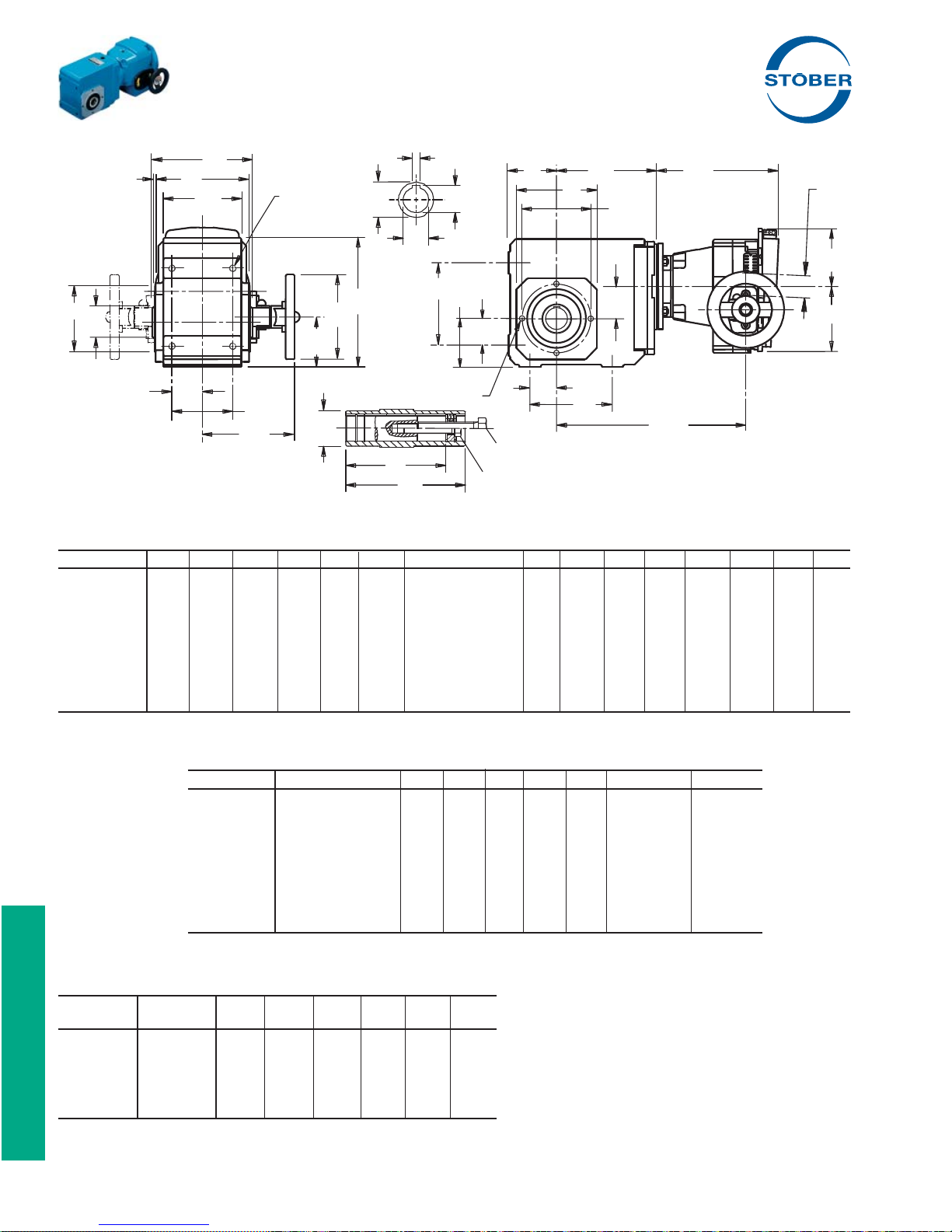
"K" Series – MGS® Adjustable Speed Drives
Dimensional Data
B
P
BP
J
R
2 Dia x
DP deep
8 Places
UC
1)
UA
UB
S
T
A
TL
X
BC
U
Z
M
UC
GA
DH
2
H
J
G
D
HL
UC
F
H
1 Dia x DP deep
CD
Y
FA
FA
F
I
1
Drawing for Units
UL
B
2
K102AG — K403AG
Table No. 1 "K" Series – Tapped Hole Unit Dimensions (Inches) – "G" Housing Style
Base Module A B D F G H M Tolerance P R S Z1 BC BP FA GA
K102 4.13 4.72 6.30 3.54 2.76 2.36 2.953 +.0007/-.0005 .12 3.54 2.36 — 3.54 4.41 1.18 1.38
K202/203 4.57 5.83 7.48 4.53 3.54 2.56 3.228 +.0007/-.0005 .12 4.53 2.56 — 3.94 5.28 1.38 1.77
K302/303 5.20 6.30 8.39 5.12 4.13 2.95 3.740 +.0007/-.0005 .12 5.12 2.95 — 4.53 5.75 1.57 2.07
K402/403 5.98 7.40 9.45 6.10 4.72 3.54 4.331 +.0007/-.0005 .14 5.83 3.54 — 5.12 6.81 1.97 2.36
K513/514 5.71 7.87 10.24 5.51 4.92 6.30 4.331 +.0007/-.0005 .14 6.30 3.94 5.98 5.12 7.28 1.57 2.46
K613/614 7.09 8.46 12.20 6.30 5.12 7.48 5.512 +.0008/-.0006 .14 6.61 4.72 6.77 6.50 7.87 1.97 2.56
K713/714 7.68 9.53 13.46 7.09 5.71 8.35 6.102 +.0008/-.0006 .14 7.48 4.92 7.52 7.28 8.90 2.17 2.85
K813/814 8.90 11.81 16.14 9.45 7.28 10.43 7.283 +.0010/-.0007 .16 9.25 5.71 8.11 8.46 11.10 2.95 3.64
K913/914 11.02 13.78 19.49 11.02 8.86 12.40 9.055 +.0010/-.0007 .20 11.22 7.09 9.84 10.43 12.99 3.74 4.43
Table No. 2 "K" Series Bore Dimensions and Mounting Holes (Inches)
Base Module U Tolerance UA UB UC UL 1 J1×DP J2×DP
K102 1.0000 +.0008/-.0000 .250 1.11 1.57 3.86 1/2-13 4, M8×.51 M8×.51
K202/203 1.1875 +.0010/-.0000 .250 1.31 1.77 4.78 1/2-13 4, M8×.51 M10×.63
K302/303 1.3750 +.0010/-.0000 .312 1.52 1.97 4.92 5/8-11 4, M8×.51 M10×.63
K402/403 1.5000 +.0010/-.0000 .375 1.67 2.17 6.18 3/4-10 4, M10×.63 M12×.75
K513/514 2.0000 +.0012/-.0000 .500 2.13 2.56 6.46 3/4-10 8, M10×.63 M16×1.02
K613/614 2.0000 +.0012/-.0000 .500 2.23 2.76 7.05 3/4-10 8, M10×.63 M16×1.02
K713/714 2.3750 +.0012/-.0000 .625 2.66 3.35 8.43 1-8 8, M12×.75 M20×1.22
K813/814 2.7500 +.0012/-.0000 .625 3.03 3.94 10.35 1-8 8, M12×.75 M24×1.50
K913/914 3.2500 +.0014/-.0000 .750 3.59 4.33 11.89 1-8 8, M16×1.02 M30×1.89
1)
Table No. 3 "K" Series – Unit Dimensions (Inches)
ComTrac NEMA
Part No. C-Flange DH HL TL X Y Z
TD270K050 56C 4.92 5.67 7.87 2.09 5.55 4.41
TD270K140 143/145TC 4.92 5.67 7.87 2.09 5.55 4.41
TD370K140 143/145TC 4.92 5.91 8.50 2.17 5.67 4.37
TD470K180 182/184TC 6.30 6.81 8.94 2.80 7.20 5.59
TD570K180 182/184TC 7.87 8.31 11.89 3.11 8.11 6.30
(1)
Tapped hole are located on Side 2 of K1 units ONLY.
(2)
This dimension is a clearance hole. The mounting feet are
an integral part of the K10 housing.
Part No. Example
Hollow Output – Tapped Hole Unit with ComTrac
K402AG0350 TD470K180-300
64 STOBER Drives Inc. • ComTrac2012 • www.stober.com
Page 67
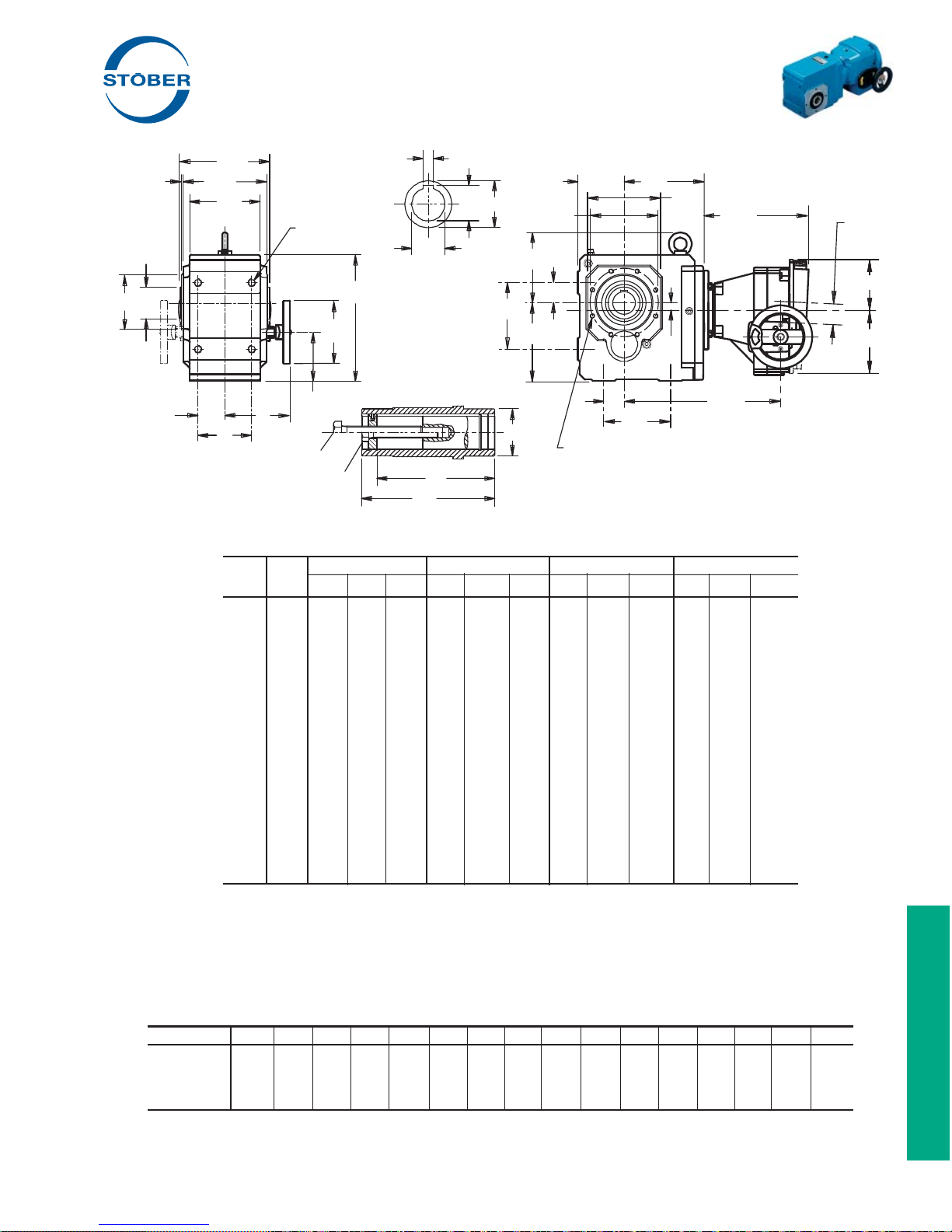
"K" Series – MGS® Adjustable Speed Drives
Dimensional Data
B
P
BP
R
2 × DP Deep
J
8 Holes as shown
M
UC
DH
2
GA
HL
H
G
1
2
UA
S
UB
UC
U
D
BC
Z
1
FA
T
A
TL
X
Z
F
H
CD
FA
UC
1 × DP Deep
J
F
UL
B
I
Drawing for Units
K513AG — K914AG
Y
Table No. 4 "K" Series – Tapped Hole Unit Dimensions (Inches) – "G" Housing Style
Base TD270K050
Module CD H
K102 1.42 2.20 7.87 5.04 1.73 8.50 5.04 — — — — — —
K202 1.81 2.80 11.97 5.79 2.32 12.64 5.79 1.17 12.76 5.87 — — —
K203 1.81 — — — — — — — — — — — —
K302 2.07 3.44 12.76 6.57 2.97 13.43 6.57 2.42 13.54 6.65 1.67 16.18 6.65
K303 .63 2.01 14.45 8.27 1.54 15.12 8.27 — — — — — —
K402 2.36 — — — 3.86 14.21 7.36 3.31 14.33 7.44 2.56 16.97 7.44
K403 .91 2.87 15.24 9.06 2.40 15.91 9.06 — — — — — —
K513 .59 — — — 3.66 13.62 6.77 3.11 13.74 6.85 2.36 16.38 6.85
K514 .59 4.13 14.65 8.46 3.66 15.31 8.46 — — — — — —
K613 .71 — — — — — — 4.17 14.49 7.60 3.43 17.13 7.60
K614 .71 5.20 15.39 9.21 4.72 16.06 9.21 — — — — — —
K713 .79 — — — — — — 4.96 15.59 8.70 4.21 18.23 8.70
K714 .79 5.98 16.54 10.35 5.51 17.20 10.35 4.96 18.03 11.14 4.21 20.67 11.14
K813 .94 — — — — — — — — — 6.14 19.25 9.72
K814 .94 — — — — — — 6.89 19.02 12.13 6.14 21.65 12.13
K913 .98 — — — — — — — — — — — —
K914 .98 — — — — — — 8.82 20.79 13.90 8.07 23.43 13.90
2 I T H2 I T H2 I T H2 I T
(3)
TD370K140 TD470K180 TD570K180
Table No. 5 "K" Series with ComTrac – Approximate Weight (lbs.)
Part Number K102 K202 K302 K303 K402 K403 K513 K514 K613 K614 K713 K714 K813 K814 K913 K914
TD270K050
TD370K140 82 91 118 124 144 151 157 160 — 228 — 285 — — — —
TD470K180 — 99 126 — 152 — 165 — 229 — 280 293 — 390 — 589
TD570K180 — — 155 — 181 — 184 — 258 — 309 322 397 410 — 618
(3)
Also available as TD270K140 for a NEMA 143TC frame motor.
STOBER Drives Inc. • ComTrac2012 • www.stober.com 65
(3)
64 73 100 106 — 133 — 142 — 210 — 267 — — — —
Page 68
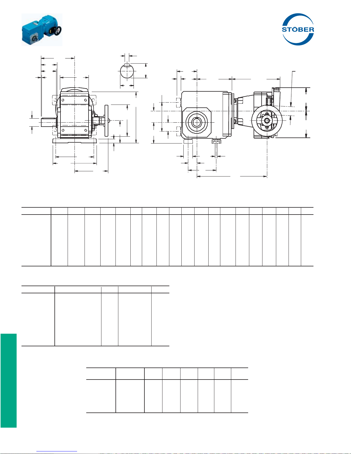
"K" Series – MGS® Adjustable Speed Drives
Dimensional Data
L
UA
P
V
Q
R
UB
N
SN
1
S
TTL
X
U
F
D
DH
U
2
H
G
N
B
HL
CD
H
FA
M
J
FA
F
Z
Y
I
Drawing for Units
K102VN — K403VN
Table No. 1 "K" Series – Foot Mounting Unit Dimensions (Inches) – "N" Housing Style
Base Module B D F G H J L M N O P Q R S Z1 BO FA N1 SN
K102 5.511) 6.97 3.54 4.53 2.95 .35 4.53 1.18 .51 — 2.34 .16 3.54 2.36 — — 1.18 .59 2.95
K202/203 7.28 8.39 4.53 6.10 3.46 .43 5.31 1.57 .79 — 2.56 .16 4.53 2.56 — — 1.38 .91 3.46
K302/303 7.87 9.29 5.12 6.69 3.86 .43 5.59 1.77 .79 — 2.60 .16 5.12 2.95 — — 1.57 .91 3.86
K402/403 9.06 10.43 6.10 7.87 4.53 .55 6.54 1.97 .87 — 3.39 .16 5.83 3.54 — — 1.97 .98 4.53
K513/514 9.45 11.42 5.51 7.87 7.48 .71 8.74 2.36 1.06 5.10 3.90 .16 6.30 3.94 5.98 7.28 1.57 1.18 5.12
K613/614 9.84 13.39 6.30 8.27 8.66 .71 9.29 2.56 1.06 5.35 4.31 .16 6.61 4.72 6.77 7.87 1.97 1.18 5.91
K713/714 11.42 14.96 7.09 9.45 9.84 .87 10.91 2.76 1.38 6.46 5.14 .16 7.48 4.92 7.52 8.90 2.17 1.50 6.42
K813/814 14.17 17.91 9.45 11.81 12.20 1.02 12.83 3.35 1.61 7.28 5.94 .20 9.25 5.71 8.11 11.10 2.95 1.77 7.48
K913/914 16.93 21.46 11.02 14.17 14.37 1.30 15.16 3.74 1.81 8.66 7.13 .31 11.22 7.09 9.84 12.99 3.74 1.97 9.06
Table No. 2 "K" Series – Shaft Dimensions (Inches)
Base Module U Tolerance V UA – Key UB
K102 1.0000 +.0000/-.0006 1.97 1/4 × 1/4 × 11/2 1.11
K202/203 1.2500 +.0000/-.0007 2.36 1/4 × 1/4 × 115/16 1.36
K302/303 1.2500 +.0000/-.0007 2.36 1/4 × 1/4 × 115/16 1.36
K402/403 1.3750 +.0000/-.0007 2.76 5/16 × 5/16 × 25/16 1.51
K513/514 1.7500 +.0000/-.0007 3.54 3/8 × 3/8 × 35/32 1.92
K613/614 1.7500 +.0000/-.0007 3.94 3/8 × 3/8 × 35/32 1.92
K713/714 2.3750 +.0000/-.0008 4.72 5/8 × 5/8 × 315/16 2.65
K813/814 2.8750 +.0000/-.0008 5.51 3/4 × 3/4 × 45/16 3.21
K913/914 3.6250 +.0000/-.0009 6.69 7/8 × 7/8 × 51/2 4.01
Table No. 3 "K" Series – Unit Dimensions (Inches)
ComTrac NEMA
Part No. C-Flange DH HL TL X Y Z
TD270K050 56C 4.92 5.67 7.87 2.09 5.55 4.41
TD270K140 143/145TC 4.92 5.67 7.87 2.09 5.55 4.41
TD370K140 143/145TC 4.92 5.91 8.50 2.17 5.67 4.37
TD470K180 182/184TC 6.30 6.81 8.94 2.80 7.20 5.59
TD570K180 182/184TC 7.87 8.31 11.89 3.11 8.11 6.30
66 STOBER Drives Inc. • ComTrac2012 • www.stober.com
(1)
Mounting feet can be bolted to Side 2 of K1 units ONLY.
Mounting feet are an integral part of the K10 housing.
Part No. Example
Foot Mounting Unit with ComTrac
K402VN0350 TD470K180-300
Page 69
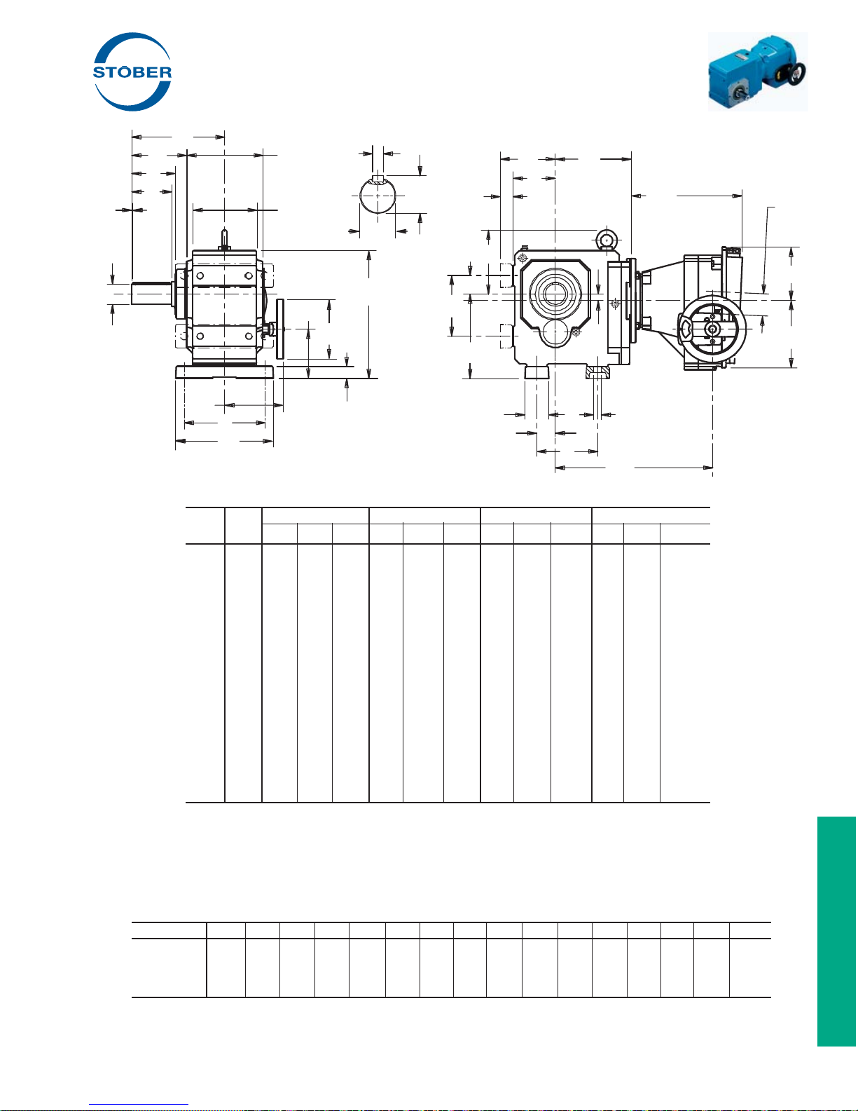
"K" Series – MGS® Adjustable Speed Drives
Dimensional Data
L
O
BO
P
V
Q
R
U
UA
SN
T
S
UB
1
N
TL
X
U
Z
1
D
2
H
DH
FA
F
CD
Z
Y
H
HL
G
B
N
Drawing for Units
K513VN — K914VN
M
J
FA
F
I
Table No. 4 "K" Series – Unit Dimensions (Inches) – "N" Housing Style
Base TD270K050
Module CD H2 I T H2 I T H2 I T H2 I T
K102 1.42 2.20 7.87 5.04 1.73 8.50 5.04 — — — — — —
K202 1.81 2.80 11.97 5.79 2.32 12.64 5.79 1.17 12.76 5.87 — — —
K203 1.81 — — — — — — — — — — — —
K302 2.07 3.44 12.76 6.57 2.97 13.43 6.57 2.42 13.54 6.65 1.67 16.18 6.65
K303 .63 2.01 14.45 8.27 1.54 15.12 8.27 — — — — — —
K402 2.36 — — — 3.86 14.21 7.36 3.31 14.33 7.44 2.56 16.97 7.44
K403 .91 2.87 15.24 9.06 2.40 15.91 9.06 — — — — — —
K513 .59 — — — 3.66 13.62 6.77 3.11 13.74 6.85 2.36 16.38 6.85
K514 .59 4.13 14.65 8.46 3.66 15.31 8.46 — — — — — —
K613 .71 — — — — — — 4.17 14.49 7.60 3.43 17.13 7.60
K614 .71 5.20 15.39 9.21 4.72 16.06 9.21 — — — — — —
K713 .79 — — — — — — 4.96 15.59 8.70 4.21 18.23 8.70
K714 .79 5.98 16.54 10.35 5.51 17.20 10.35 4.96 18.03 11.14 4.21 20.67 11.14
K813 .94 — — — — — — — — — 6.14 19.25 9.72
K814 .94 — — — — — — 6.89 19.02 12.13 6.14 21.65 12.13
K913 .98 — — — — — — — — — — — —
K914 .98 — — — — — — 8.82 20.79 13.90 8.07 23.43 13.90
(3)
Also available for a NEMA 143TC frame motor.
(3)
TD370K140 TD470K180 TD570K180
Table No. 5 "K" Series with ComTrac – Approximate Weight (lbs.)
Part Number K102 K202 K302 K303 K402 K403 K513 K514 K613 K614 K713 K714 K813 K814 K913 K914
TD270K050
TD370K140 82 91 118 124 144 151 157 160 — 228 — 285 — — — —
TD470K180 — 99 126 — 152 — 165 — 229 — 280 293 — 390 — 589
TD570K180 — — 155 — 181 — 184 — 258 — 309 322 397 410 — 618
(2)
Also available as TD270K140 for a NEMA 143TC frame motor.
STOBER Drives Inc. • ComTrac2012 • www.stober.com 67
(2)
64 73 100 106 — 133 — 142 — 210 — 267 — — — —
Page 70
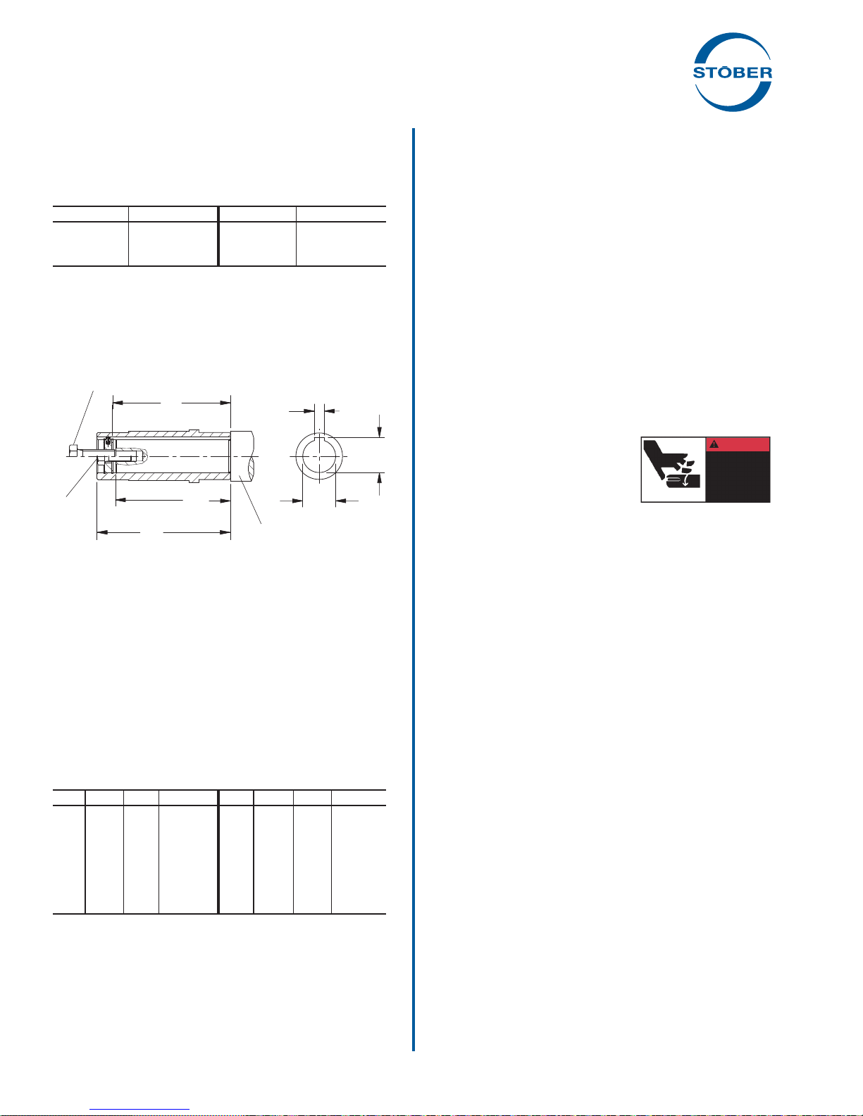
MGS® Adjustable Speed Drives
Lubrication and Mounting Information
Mounting Hollow Output Reducers
A STOBER hollow output reducer can be mounted from either
side. The tolerance for the hollow bore is shown in Table No. 1
and the shaft should be toleranced to fi t this bore accordingly.
Table No. 1 Hollow Output Bore Tolerance
Bore Range Tolerance Bore Range Tolerance
.39 — .71 +.0007/-.0000 1.97 — 3.15 +.0012/-.0000
.71 — 1.18 +.0008/-.0000 3.15 & UP +.0014/-.0000
1.18 — 1.97 +.0010/-.0000
A keeper plate inside the quill is provided with each unit to prevent
axial movement. This keeper plate is held in place with snap rings
and can be easily removed for location on either end. A spring
pin in the keeper plate mounts into the keyway of the quill and
prevents rotation. The keeper plate center hole is tapped to fi t the
removal bolt.
Removal Bolt
Mounting
Bolt
"UL"
Length to Keeper Plate
"UL - .125"
Length of Shaft
"B"
Length Thru Quill
Keyway
Width
Keyway
Height
Output
Bore
Machine Shaft
with Shoulder
Before installation, brush the inside of the quill with rust inhibiting
grease. When mounting the unit onto the shaft, avoid hammering
as this may damage the bearings. Do not mount the reducer dry
as removal may be impossible.
The drawing above shows a mounting or fi xing bolt and a re-
moval bolt. The mounting/fi xing bolt should be smaller in size
than the removal bolt. See Table No. 4.
To use the keeper plate with a mounting/fi xing bolt, drill and tap
the end of the shaft that will be mounted into the reducer. Insert
the mounting/fi xing bolt through the keeper plate and thread into
the shaft end. The machine shaft length should not be longer than
the “UL” dimension. A shaft length of "UL minus .125" inches will
allow the shaft shoulder to pull against the face of the quill of the
reducer.
Table No. 2 "UL" Dimension and Removal Bolt Size
Unit Bore UL Bolt Unit Bore UL Bolt
F1 .750 2.67
F2 1.000 3.62
F3 1.250 4.06
F4 1.500 4.49
F6 2.000 5.63
K8 2.750 10.35 1-8 NC
K1 1.000 3.86
K2 1.187 4.78
3
/8-16 NC K3 1.375 4.92 5/8-11 NC
1
/2-13 NC K4 1.500 6.18 3/4-10 NC
1
/2-13 NC K5 2.000 6.46 3/4-10 NC
3
/4-10 NC K6 2.000 7.05 3/4-10 NC
3
/4-10 NC K7 2.375 8.43 1-8 NC
1
/2-13 NC K9 3.250 11.89 1-8 NC
1
/2-13 NC
Removal of Hollow Output Reducers
To dismantle the unit from the shaft, remove the mounting bolt.
Thread the removal bolt into the keeper plate to press against the
shaft and loosen the shaft from the unit. Removal of the reducer
will be easier if the quill is greased before installation.
See our web site (www.stober.com) for a parts breakdown of a
specifi c reducer or call STOBER Customer Service.
In order to obtain long life and trouble-free operation from your
MGS speed reducer, it is essential that recommended installation
and operating procedures be followed.
Included here are directions for mounting and start-up of the MGS
unit, as well as lubrication and maintenance instructions. Failure
to follow these instructions will void the drive's warranty.
The torque required by the application must not exceed the
reducer torque capacity shown on the nameplate. For safety purposes a safety coupling should be installed between the reducer
and the driven load. Otherwise, overload may cause damage to
the interior parts of the reducer which may result in breaking the
reducer housing. As a result, persons could be injured by fl ying
parts or splashing hot gear oil.
If you have questions about the installation, operation or maintenance of your MGS unit, please contact your local Stober distributor for assistance.
WARNING:
Safety is the most important consideration when operating any
type of drive. Through proper application, safe handling methods,
and wearing appropriate clothing, you can prevent accidents and
injury to yourself and fellow workers.
The shafts of MGS speed reducers
rotate at very high speeds and can cut
off or severely injure hands, fi ngers,
and arms. Use appropriate guards
for shafts and other rotating parts at
all times. Follow all directions in the
service instruction manual. Obey all federal, state and local safety
regulations when operating the drive.
• Always be sure electrical power is off while making electrical
connections and during installation and maintenance of the
unit.
• Keep clothing, hands, and tools away from ventilation openings on motors and from all rotating parts during operation.
• Lift drive with a double rope sling or other proper lifting equipment of adequate strength. Make sure load is secured and
balanced to prevent shifting when unit is being moved. Lifting
drives by hand may be dangerous and should be avoided.
• The intended use of lifting lugs is to handle the weight of the
unit only. Never use a lifting lug to lift attached assemblies.
• Never operate drive at speeds higher than those shown on
the nameplate, or personal injury may result. Contact Stober
Drives Inc., if there is any change of operating conditions from
those for which the unit was originally sold (as stamped on the
nameplate). Failure to comply could result in personal injury
and or machinery damage.
• Always follow good safety practices at all times.
Each drive is tested before delivery. Before installation, however,
it is advisable to examine the unit for possible damage which
might have occurred during transit. If damage is discovered, it
should be immediately reported to the transport agent.
If installation is delayed after receipt of the MGS speed reducer,
the drive should be stored in a clean, dry place until put into
service. Long term storage requires special procedures. If not
kept in a heated, dry area, consult Stober Drives, Inc. for storage
instructions.
NOTE: If it is necessary to clean drive shafts, take care to protect
the oil seals.
IMPORTANT: Do not use any device to hammer the unit onto the
output shaft during installation since the bearing races could be
damaged.
WARNING
Cover rotating
parts with safety
guard before
turning on
power.
68 STOBER Drives Inc. • ComTrac2012 • www.stober.com
Page 71
MGS® Adjustable Speed Drives
Lubrication and Mounting Information
Lubrication and Mounting Position
All STOBER units are shipped fi lled with the required amount
of lubrication. In order to provide the proper lubrication quantity
the mounting position required should be specifi ed at the time of
order. No unit will be shipped without the mounting position
specifi ed by the customer.
Vertical mounting may require different seals, bearings, etc. so it
is very important to mount the unit in the position for which it was
assembled.
Table No. 1 shows standard lubricant characteristics.
1
4
Table No. 1
Characteristic of STOBER Standard Lubricants
Exxon
Special Mist
MobilGear EP220 Mobilgear
XP600 Food Grade SHC630
Anti-Foaming Additives 4 4 Excellent
Corrosion Protection 4 4 Optimum
Extreme Pressure Additives 4 4 4
Friction and Wear
Reducing Characteristics 4 4 Superior
Oxidation Protection 4 4 Enhanced
Wide Temperature Range 4
If food grade or synthetic oil is requested, it will be Mobilgear Special
Mist EP220 food grade or Mobilgear SHC630 synthetic.
Maintenance
With STOBER reducers very little maintenance is required under
normal operating conditions.
Breathers are provided on the following units:
C612 through C913
K513 through K914
See Table No. 2 and 3 for location of drain and vent for each series
and mounting position.
We recommend that the lubrication be changed in units supplied
with breathers according to the following schedule:
Normal Operating Conditions after 5000 Hours
Wet Operating Conditions after 2000 Hours.
Units supplied without breathers are lubricated for life.
2
3
Table No. 2 Drain Plug and Vent Location
Mounting Position 1 2 2a 3 4
EL1 Vent Drain
EL2 Drain Vent
EL3 Vent Drain
EL4 Drain Vent
EL5(C612-C912) Drain Vent
EL5(C613-C913) Drain Vent
EL6 Vent Drain
Position 2a is on the opposite side of 2.
1
4
2
3
Table No. 3 Drain Plug and Vent Location
Mounting Position 1 2 2a 3 4
EL1 Vent Drain
EL2 Drain Vent
EL3 Vent Drain
EL4 Drain Vent
EL5(K513/K913) Drain Vent
EL5(K514/K914) Drain Vent
EL6(K513/K913) Vent Drain
EL6(K513/K914) Vent Drain
Position 2a is on the opposite side of 2.
Some motor manufacturers provide a drain hole in the
mounting face of washdown motors. Be sure this hole
is covered during washing or when the unit is used in a
wet environment.
STOBER Drives Inc. • ComTrac2012 • www.stober.com 69
Page 72
MGS® Adjustable Speed Drives
Mounting Information
Mounting position must be specifi ed when the order is placed.
ComTrac Location
The position of the ComTrac and the handwheel location can be specifi ed at the time of assembly.
Specify by ComTrac position I thru IV with handwheel L (left) or R (right).
IV is the standard position — with the handwheel on the left (L) as shown.
If no specifi cation is made, units will be shipped with the standard position.
Table No. 1 "C" Series – Mounting Position
EL1 EL2 EL3 EL4 EL5 EL6
Side 1 Side 2 Side 3 Side 4 Side 5 Side 6
III
II
L I
IV
"C" Series
Table No. 2 "F" Series – Mounting Position
EL1 EL2 EL3 EL4 EL5 EL6
Side 1 Side 2 Side 3 Side 4 Side 5 Side 6
III
II
L I
IV
"F" Series
70 STOBER Drives Inc. • ComTrac2012 • www.stober.com
Page 73
MGS® Adjustable Speed Drives
Mounting Information
Mounting position must be specifi ed when the order is placed.
Table No. 3 "K1-K4" Series – Mounting Position
EL1 EL2 EL3 EL4 EL5 EL6
Table No. 4 "K5-K9" Series – Mounting Position
EL1 EL2 EL3 EL4 EL5 EL6
Side 1 Side 2 Side 3 Side 4 Side 5 Side 6
III
II
L I
IV
"K" Series
STOBER Drives Inc. • ComTrac2012 • www.stober.com 71
Side 1 Side 2 Side 3 Side 4 Side 5 Side 6
Page 74

Terms and Conditions of Sale
1. GENERAL. All orders for products supplied by
STOBER DRIVES INC. (“STOBER”) shall be subject
to these terms and conditions of sales. All transactions
shall be governed by the laws of the Commonwealth
of Kentucky. No modifi cations hereto will be binding
unless agreed to in writing by STOBER.
2. CUSTOMER. The term “Customer,” as used
herein, means the distributor, resale dealer, original
equipment manufacturer or fi rst end-user customer
that purchases the STOBER products.
3. WARRANTY. STOBER products shall be free from
defects in material and workmanship for a maximum
of 5-years (single shift operation or 30 months multiple
shift operation) for ServoFit products and MGS Long
Life products; 3-years (single shift operation or 18
months multiple shift operation) for MGS products;
2-years (single shift operation or 12 months multiple
shift operation) for TD products, from the date of
shipment to the Customer. For ServoFit products, all
normal wear items, including oil seals and bearings,
shall be covered for a period of 2-years (single shift
operation or 12 months multiple shift operation). In the
event that a product proves to be defective, STOBER’s
sole obligation shall be, at its option, to repair or replace
the product. The repaired or replacement product will
be shipped F .O.B. STOBER’s facilities, freight prepaid
by STOBER.
No employee, agent or representative of STOBER
has the authority to waive, alter, vary or add to the
terms hereof without the prior written approval of an
offi cer of STOBER. It is expressly agreed that (a) this
section constitutes the fi nal expression of the parties’
understanding with respect to the warranty and (b)
this section is a complete and exclusive statement of
the terms of the warranty.
STOBER shall have no obligation under the warranty
set forth above in the event that:
(a) The Customer fails, within the warranty period to
notify STOBER in writing and provide STOBER
with evidence satisfactory to STOBER of the
alleged defect within fi ve (5) days after it becomes
known to the customer;
(b) After inspection of a product, STOBER determines,
in its sole discretion, that it is not defective in
material or workmanship;
(c) Repair or replacement of a product is required
through normal wear and tear;
(d) Any part in a product or any ingredient contained
in a product requires replacement or repair through
routine usage or normal wear and tear;
(e) A product is not maintained or used in accordance
with STOBER’s applicable operating and/or
maintenance manuals, whether by the Customer
or any third party;
(f) A product has been subject to misuse,
misapplication, negligence, neglect (including, but
not limited to, improper maintenance or storage),
accident, catastrophe, improper installation,
modifi cation, adjustment, repair or lubrication,
whether by the Customer or any third party, without
the prior written consent of STOBER. Misuse shall
include, but not be limited to, deterioration in a
product due to chemical action and wear caused
by the presence of abrasive materials;
(g) The system of connected rotating parts into
which the product becomes incorporated is not
compatible with the product, or it is not free from
critical speed or torsional or other type of vibration
within the specifi ed operating range, no matter
how induced; or
(h) The transmitted load and imposed torsional thrust
and overhung loads are not within the published
capacity limits for the unit sold.
Items manufactured by other parties but installed in
or affi xed to STOBER’s products are not warranted
by STOBER and bear only those warranties, express
or implied, which are given by the manufacturer of
such items, if any.
THE WARRANTY SET FORTH ABOVE IS INTENDED
SOLELY FOR THE BENEFIT OF THE Customer
AND DOES NOT APPLY TO ANY THIRD PARTY.
ALL CLAIMS MUST BE MADE BY THE Customer
AND MAY NOT BE MADE BY ANY THIRD PARTY.
THIS WARRANTY MAY NOT BE TRANSFERRED
OR ASSIGNED, IN WHOLE OR IN PART, BY THE
Customer FOR ANY REASON WHA TSOEVER. ANY
SUCH ATTEMPTED TRANSFER OR ASSIGNMENT
SHALL BE NULL AND VOID.
THIS WARRANTY TAKES THE PLACE OF ALL
OTHER WARRANTIES, EXPRESS OR IMPLIED,
WHICH ARE HEREBY DISCLAIMED AND EXCLUDED
BY STOBER, INCLUDING WITHOUT LIMITATION,
ANY WARRANTY OF MERCHANTABILITY OR
FITNESS FOR A PARTICULAR PURPOSE OF USE
AND ALL OBLIGATIONS OR LIABILITIES ON THE
PART OF STOBER FOR DAMAGES ARISING OUT
OF OR IN CONNECTION WITH THE USE, REPAIR
OR PERFORMANCE OF THE PRODUCTS.
4. MODIFICATIONS. STOBER reserves the right,
without notice to the Customer, to (a) change the
specifi cations of any product, (b) improve a product
in any manner that STOBER deems necessary or
appropriate and (c) discontinue the manufacture of
any product.
5. PURCHASE ORDERS. The Customer will
submit purchase orders for the products to STOBER
in writing, whether by mail or telefax, which shall set
forth, at a minimum: (a) an identifi cation of the products
ordered, (b) prices for such products, (c) quantities, (d)
requested delivery dates and (e) shipping instructions
and shipping addresses.
6. ACCEPT ANCE OF ORDERS. All purchase orders
received from the Customer are subject to acceptance
by STOBER in writing.
7. MODIFICATION OF ORDERS. No accepted
purchase order shall be modifi ed or canceled except
upon the written agreement of STOBER and the
Customer. Mutually agreed cancellations shall be
subject to reasonable charges based upon expenses
already incurred by STOBER and commitments made
by STOBER. Mutually agreed change orders shall be
subject to all provisions of these T erms and Conditions
of Sale.
8. PRICE INCREASES. STOBER may increase
its prices for the products by providing the original
purchaser of the products with at least thirty (30) days’
prior written notice. Increased prices for products
shall not apply to purchase orders accepted prior to
the effective date of the price increase unless such
orders provide for delivery more than thirty (30) days
after the date of acceptance of the order.
9. PRICING AND DELIVER Y TERMS. In accordance
with KRS 355.2-319(1)(b), all products are delivered
F.O.B. STOBER's warehouse facility in Maysville,
Kentucky, or such other facility as STOBER may
designate. Orders are then shipped per Customer's
shipping instructions as set forth in Customer's
purchase order. CATALOG PRICING DOES NOT
INCLUDE SHIPPING, HANDLING AND TAXES.
Once delivered to a common carrier of the Customer's
choosing [or of STOBER's choosing if Customer has
failed to specify a common carrier on or before fi ve
(5) days prior to the requested delivery date] STOBER
shall have no further responsibility for the products
and all risk of damage, loss or delay shall pass to the
Customer. A handling fee is added to freight costs by
STOBER to cover the cost of having to pay the carrier
within seven (7) days when the terms with the Customer
are net 30. The Customer has the option of shipping
collect with our carrier or the carrier of choice.
10. PAYMENT TERMS. Net 30 days. All orders
will be shipped either prepaid by the Customer or
C.O.D., at STOBER’s option, unless the Customer
has established a previously approved credit line. If
STOBER approves a credit line for the Customer, all
payments shall be due within thirty (30) days of the date
of the invoice. If any invoice is not paid in full within
such thirty (30) day period, then fi nance charges shall
be assessed at the rate of one and one-half percent
11/2%
) per month (eighteen percent (18%) per year).
(
If such rate is deemed to be usurious at any time,
it shall be reduced to the maximum rate permitted
by applicable law. STOBER may stop or withhold
shipment of products if the Customer does not fulfi ll
its payment obligations. If STOBER is insecure about
payment for any reason, STOBER may require full or
partial payment in advance and as a condition to the
continuation of its delivery of products.
11. SECURITY INTEREST. Unless and until the
products are paid for in full, STOBER reserves a
security interest in them to secure the unpaid balance
of the purchase price. The Customer hereby grants to
STOBER a power of attorney, coupled with an interest,
to execute and fi le on behalf of the Customer all
necessary fi nancing statements and other documents
required or appropriate to protect the security interest
granted herein.
12. ACCEPT ANCE OF PRODUCTS. The Customer
will conduct any incoming inspection tests as soon as
possible upon arrival of the products, but in no event
later than ten (10) days after the date of receipt. Any
products not rejected by written notice to STOBER
within such period shall be deemed accepted by
the Customer. STOBER shall not be liable for any
additional costs, expenses or damages incurred by
the Customer, directly or indirectly, as a result of any
shortage, damage or discrepancy in a shipment.
13. LIMITATION OF REMEDIES.
(a) STOBER SHALL NOT BE LIABLE FOR ANY
LOSS OR DAMAGE CAUSED BY DELAY
IN FURNISHING THE CUSTOMER WITH
PRODUCTS.
(b) IN NO EVENT SHALL STOBER’S LIABILITY
INCLUDE ANY SPECIAL, INDIRECT,
INCIDENTAL OR CONSEQUENTIAL
LOSSES OR DAMAGES, EVEN IF STOBER
HAS BEEN ADVISED OF THE POSSIBILITY
OF SUCH POTENTIAL LOSS OR DAMAGE.
14. MADE-TO-ORDER PRODUCTS. STOBER
reserves the right to revoke and amend any price
quotations offered to the Customer for made-to-order
products, provided that such price quotations have not
been accepted by the Customer prior to the date of
revocation or amendment.
15. DIES, TOOLS AND EQUIPMENT. Charges
incurred by the Customer for dies, tools and other
equipment shall not confer ownership or the right to
possession therein by the Customer. All such dies,
tools and equipment shall remain the property of
STOBER, and STOBER shall have the exclusive right
to possession thereof. STOBER shall maintain such
tools and equipment in good working order.
16. REGULATORY LAWS AND STANDARDS.
STOBER makes no representation that its products
conform to state or local laws, ordinances, regulations,
codes or standards except as may be otherwise agreed
to in writing by STOBER.
17. SIZES AND WEIGHTS. STOBER’s products
are made only in the sizes and to the specifi cations
set forth in its catalogs and other literature. If any
alteration is requested, such altered product will be
treated as a made-to-order item. STOBER assumes
no responsibility for typographical errors which may
appear in its catalogs or literature, and cannot accept
alteration charges caused by such errors. Since
weights shown in STOBER’s catalogs are approximate,
they cannot be used in determining freight allowances
set forth in its catalogs and other literature. Freight
allowances will be determined at the time of shipment
and shall be based on actual shipping weight.
18. SYSTEM DESIGN. Responsibility for system
design to ensure proper use and application
of STOBER’s products within their published
specifications and ratings rests solely with the
Customer. This includes, but is not limited to, an
analysis of loads created by torsional vibrations within
the entire system, regardless of how induced.
72 STOBER Drives Inc. • ComTrac2012 • www.stober.com
Page 75

Page 76
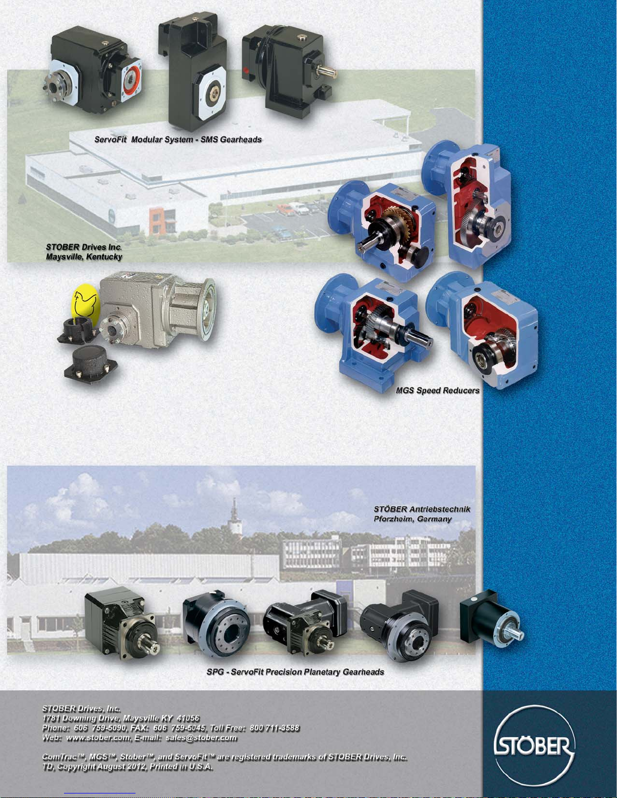
 Loading...