

Page 1

UM2669
User manual
Getting started with X-CUBE-SUBG2, Sub-1 GHz RF software expansion for
STM32Cube
Introduction
X-CUBE-SUBG2 is an expansion software package for STM32Cube. The software runs on the STM32 and includes drivers that
recognize the Sub-1 GHz RF communication for S2-LP.
The expansion is built on STM32Cube software technology to ease portability across dif
The software comes with sample applications of P2P and 6LoWPAN communication protocols, running on an X-NUCLEO-
S2868A2 or X-NUCLEO-S2915A1 expansion board when connected to a compatible STM32 Nucleo development board.
RELATED LINKS
Visit the STM32Cube ecosystem web page on www.st.com for further information
ferent STM32 microcontrollers.
UM2669 - Rev 3 - December 2020
For further information contact your local STMicroelectronics sales of
fice.
www.st.com
Page 2

1 Acronyms and abbreviations
Table 1. List of acronyms
Acronym Description
GHz Giga Hertz
AMR Automatic Meter Reading
EEPROM Electrically erasable programmable read-only memory
GUI Graphical User Interface
P2P Point-to-Point communication
RF Radio frequency
MCU Microcontroller unit
P2P Point-to-Point communication
HAL Hardware Abstraction Layer
SPI Serial peripheral interface
USB Universal Serial Bus
NVIC Nested Vectored Interrupt Controller
WSN Wireless sensors network
BSP Board support package
LED Light emitting diode
IPv6 Internet Protocol vers. 6
UDP User Datagram Protocol
TCP Transmission Control Protocol
6LoWPAN IPv6 over Low -Power Wireless Personal Area Networks
RPL Routing Protocol for Low-Power and Lossy Networks
MAC Medium Access Control
CSMA Carrier-sense multiple access
DMA Direct Memory Access
USART Universal Synchronous Asynchronous Receiver Transmitter
wM-Bus Wireless metering bus
UM2669
Acronyms and abbreviations
UM2669 - Rev 3
page 2/39
Page 3

X-CUBE-SUBG2 software expansion for STM32Cube
2 X-CUBE-SUBG2 software expansion for STM32Cube
2.1 Overview
X-CUBE-SUBG2 software package expands STM32Cube
The key features of the package are:
• Firmware package to start developing using S2-LP expansion boards
• Point-to-point communication sample application for simple buffer transmission and acknowledgement
implementation
• Contiki-NG based applications for 6LoWPAN connectivity
• Low-power optimizations for the STM32 MCU family
• Easy portability across different MCU families thanks to STM32Cube
• Package compatible with STM32CubeMX, can be downloaded from and installed directly into
STM32CubeMX
• Free user-friendly license terms
• Sample implementation available on X-NUCLEO-S2868A1, X-NUCLEO-S2868A2 or X-NUCLEO-S2915A1
expansion boards when connected to NUCLEO-F401RE, NUCLEO-L053R8 or NUCLEO-L152RE
development boards
Starting from this software, it is possible to develop other applications, such as:
• automatic meter reading
• home and building automation
• industrial monitoring and control
• wireless fire and security alarm systems
The firmware partitioning among the STM32 microcontroller on the STM32 Nucleo development boards and the
S2-LP is:
• STM32 MCU
– P2P and 6LowPAN applications implementation
– low power mode handling
– interrupt services
• S2-LP role
– basic/stack modes
– header, sync and trailer fields
– encoding/decoding
– sync detection
– RX and TX 128 bytes FIFO buffers
– IEEE 802.15.4g hardware packet support with whitening, FEC, CRC and dual sync word detection.
functionality .
UM2669
2.2 Architecture
This software is fully compliant with and expands STM32Cube
NUCLEO-S2868A1, X-NUCLEO-S2868A2 or X-NUCLEO-S2915A1 expansion board hosting the S2-LP devices.
The software is based on the STM32CubeHAL hardware abstraction layer for the STM32 microcontroller. The
package extends STM32Cube by providing a board support package (BSP) for the S2-LP expansion board and
firmware examples for P2P communication.
UM2669 - Rev 3
to enable development of applications using X-
page 3/39
Page 4
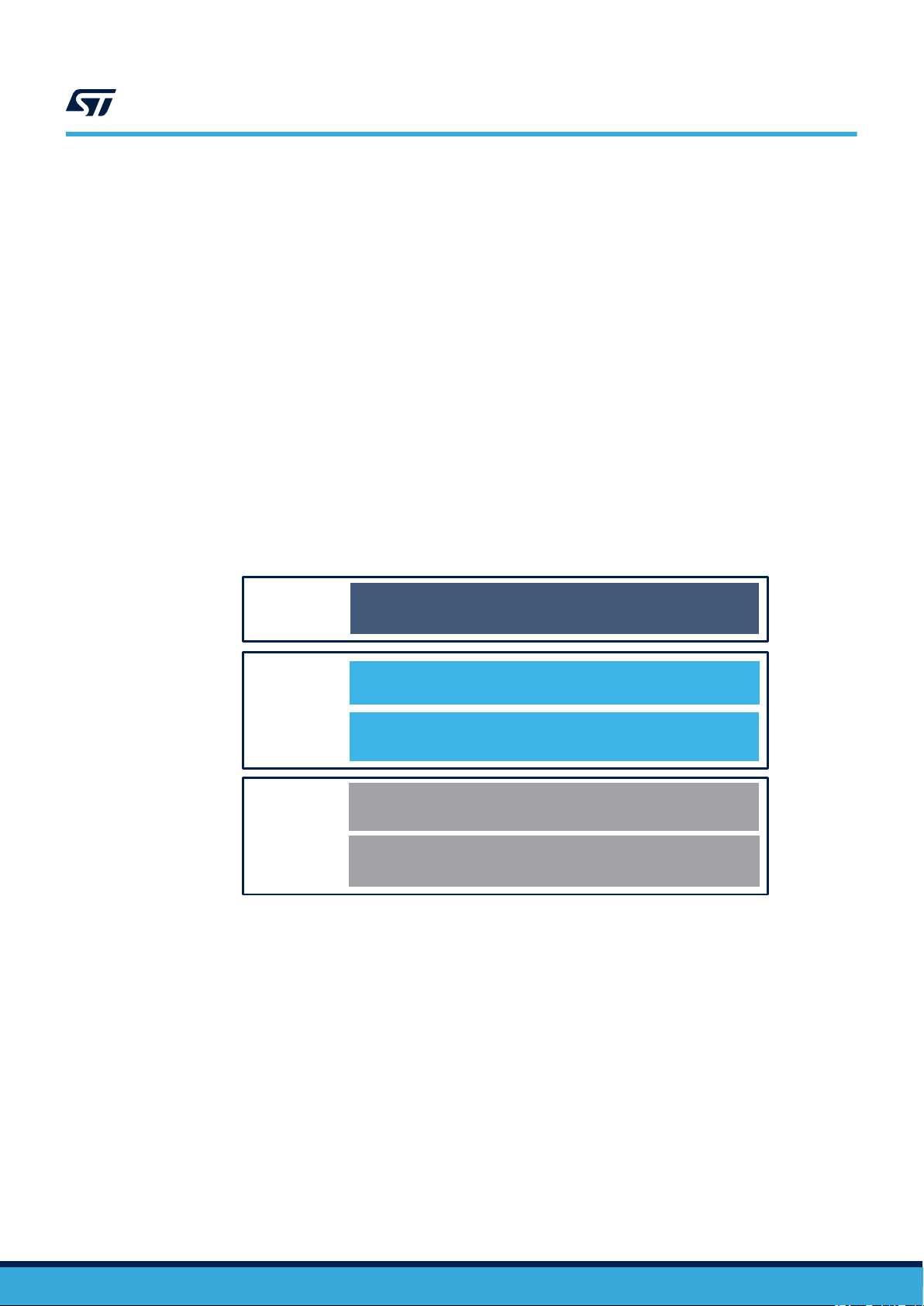
STM32Cube Hardware Abstraction Layer (HAL)
STM32 Nucleo development board
6LoWPAN
Hardware
Middleware
Hardware
Abstraction
Application
Examples
STM32 Nucleo expansion boards
X-NUCLEO-S2868A2/X-NUCLEO-S2915A1 (Connect)
UM2669
Architecture
The software layers used by the application software to access and use the S2-LP expansion board are:
STM32Cube HAL layer: provides a generic, multi-instance set of APIs to interact with the upper layers
•
(the application, libraries and stacks). It consists of generic and extension APIs based on a common
architecture which allows other layers like the middleware layer to function without specific Microcontroller
Unit (MCU) hardware configurations. This structure improves library code reusability and guarantees easy
device portability.
• Board support package (BSP) Layer: includes the software to support the peripherals on the STM32
Nucleo board (apart from the MCU). It is a set of APIs which provides a programming interface for certain
board-specific peripherals (LED, user button etc.). The X-NUCLEO-S2868A1, X-NUCLEO-S2868A2 or X-
NUCLEO-S2915A1 expansion board BSP firmware layer contains APIs for the hardware components and
consists of:
– Component driver: related to the on-board device (not related to the STM32). The S2-LP BSP driver
is known as the firmware component. The S2-LP component driver provides specific APIs and can be
ported to and used on any board.
– BSP driver: enables the component driver to be linked to a specific board and provides a set of
user-friendly APIs.
• Application layer: provides a Point-to-Point communication example for sending a buffer from one node to
another and acknowledgments using the S2-LP link layer features.
• Application layer for Contiki-NG based applications: provides 6LoWPAN communication for mesh-network
as well as featured examples for UDP Client/Server, Serial Sniffer and Border Router.
Figure 1. X-CUBE-SUBG2 software architecture
UM2669 - Rev 3
page 4/39
Page 5
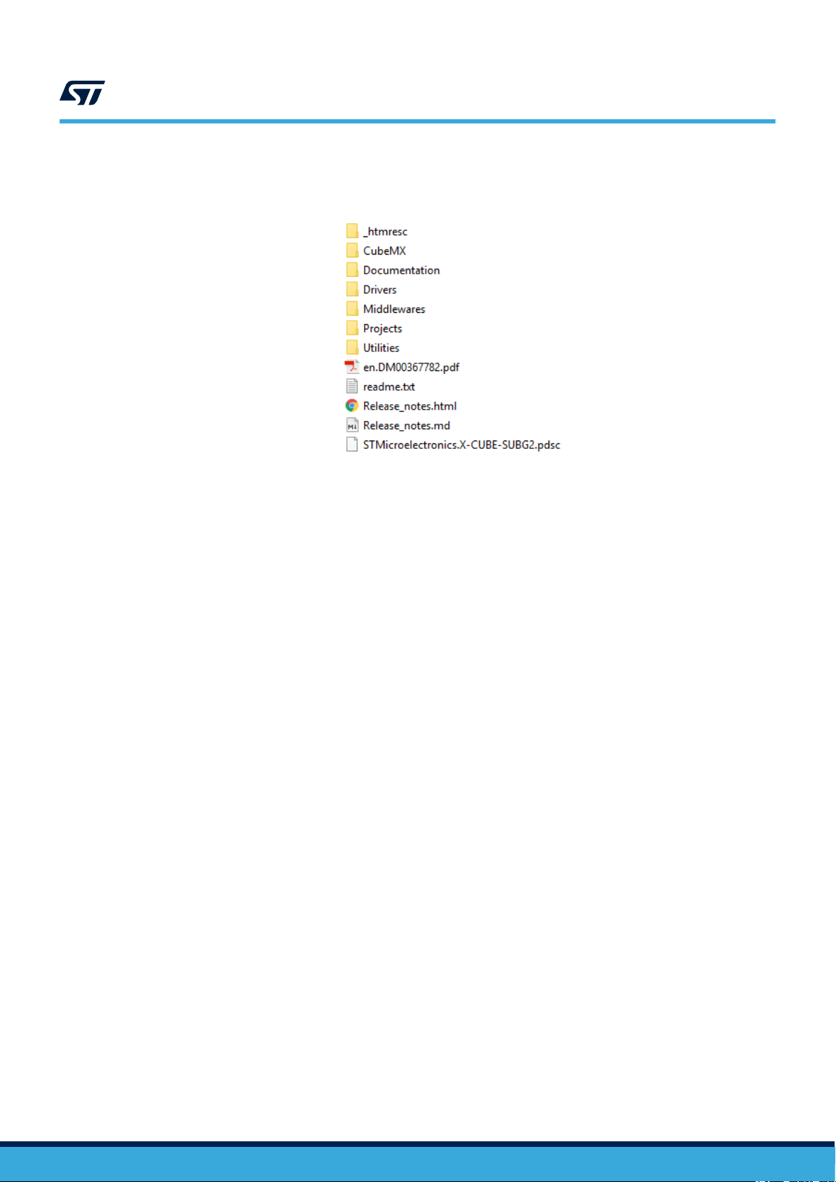
2.3 Folder structure
The software package includes the following folders:
•
‘CubeMX’: contains the meta data files for the package support in the STM32CubeMX tool.
• ‘Documentation’: contains a compiled HTML file generated from the source code and detailed
documentation of the software components and APIs
• ‘Drivers’: contains the HAL drivers and the board-specific drivers for supported board and hardware
platforms, including those for the on-board components and the CMSIS vendor-independent hardware
abstraction layer for the Cortex-M processor series
• ‘Middlewares’: contains Contiki-NG source code for 6LoWPAN communication over S2-LP radio
• ‘Projects’: contains a sample application used for P2P firmware examples and 6LoWPAN communication for
the NUCLEO-L053R8 (P2P only), NUCLEO-F401RE or NUCLEO-L152RE platforms with three development
environments (IAR Embedded Workbench for ARM (IAR-EWARM), RealView Microcontroller Development
Kit (MDK-ARM-STR) and STM32CubeIDE)
• ‘Utilities’: contains tools to be used on a host PC to interact with Serial Sniffer and Border Router firmware
applications (6LoWPAN)
UM2669
Folder structure
Figure 2. X-CUBE-SUBG2 package folder structure
2.4 APIs
Detailed descriptions of all the functions and parameters of the user APIs user can be found in a compiled HTML
file located inside the ‘Documentation’ folder
UM2669 - Rev 3
.
page 5/39
Page 6
1
2
UM2669
Point-to-Point (P2P) demo firmware description
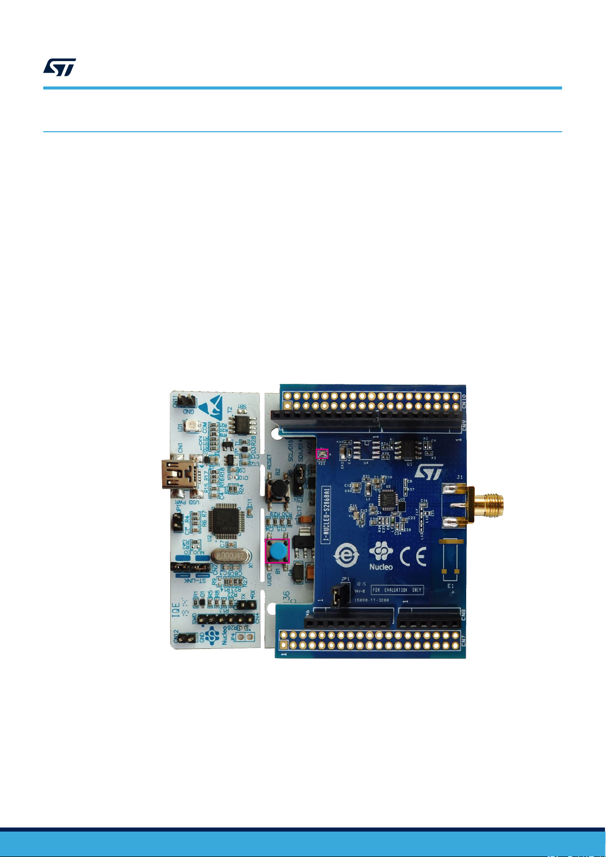
3 Point-to-Point (P2P) demo firmware description
3.1 P2P application details
The P2P application operates using two nodes (STM32 Nucleo development board plus S2-LP expansion board)
as follows:
1.
by pressing the STM32 Nucleo board user button (shown in the picture below), each node can transmit a
buffer to the other node
2. on receiving the signal, the receiver node LED lights up and an acknowledgment (ACK) signal is returned to
the transmitter node
3. on reception of the ACK signal, the transmitter node LED flashes four times and switches off after a delay
period
Figure 3. X-NUCLEO-S2868A1 plus STM32 Nucleo used as a node (transmitter/receiver) in P2P
communication
1. STM32 Nucleo user button
2. X-NUCLEO-S2868A1 expansion board LED
Note: The LED on the expansion board is mounted but not connected: only the STM32 Nucleo LED blinks during P2P
communication.
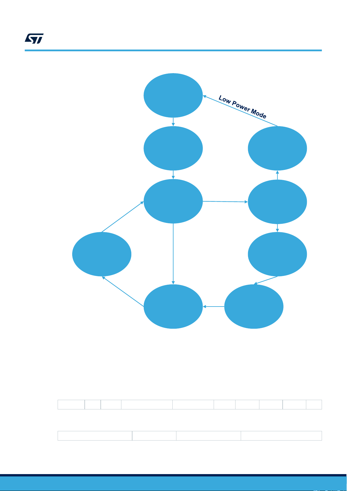
3.2 Application state diagram
When running the demo sample with the STM32 Nucleo boards, S2-LP remains by default in receive mode but
changes to transmit mode when the user button is pressed.
Once transmission stops, the transceiver returns to its default receive mode. On successful completion of the
two-way communication (Command/ Ack), the MCU enters low-power mode.
T
o limit low-power mode current consumption, the LED is switched off by default.
P2P nodes have the same functionality; the address of each node is set in the firmware by the user.
UM2669 - Rev 3
page 6/39
Page 7
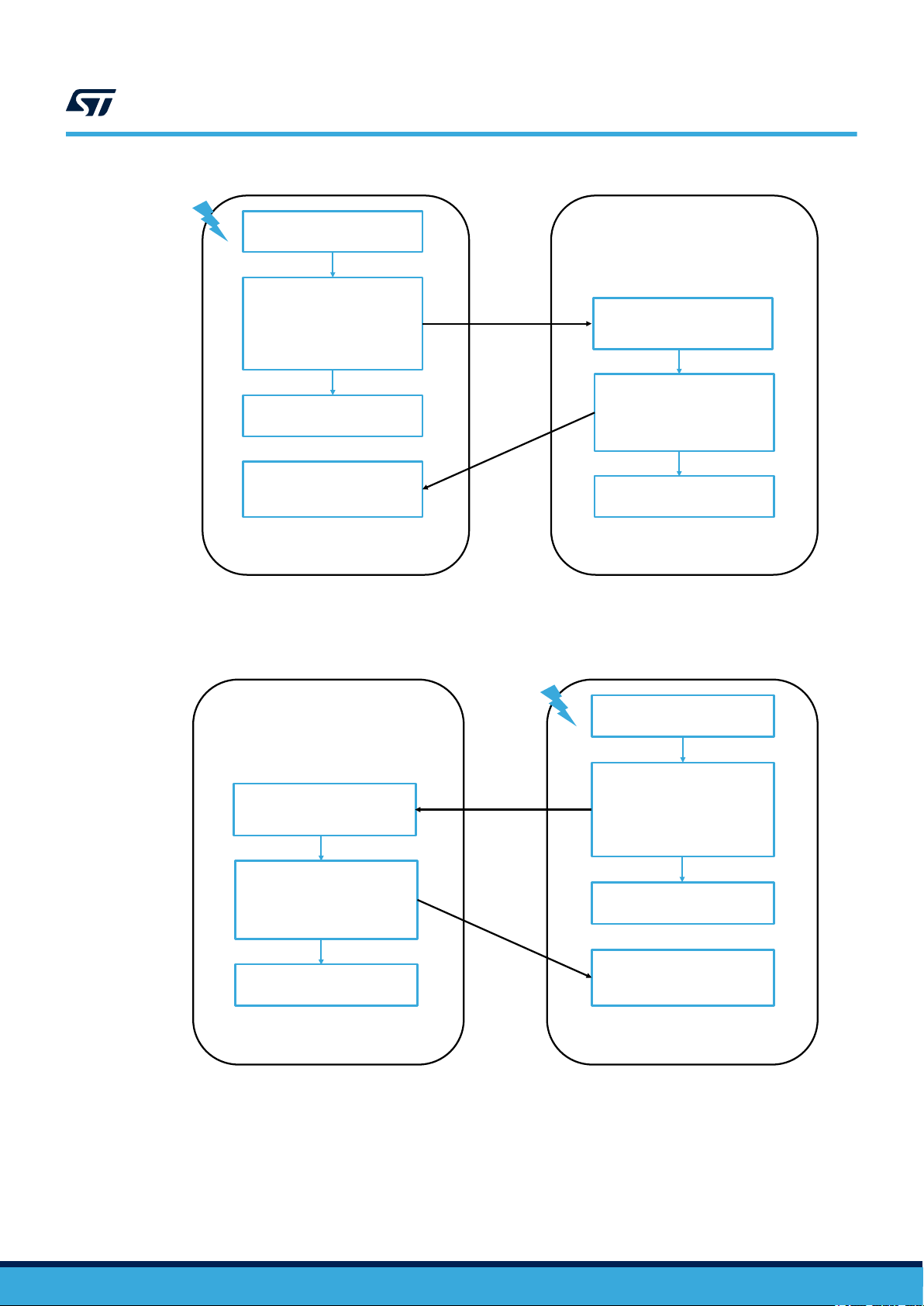
Node 1
Press SW on Nucleo
Prepared the Command
Change S2-LP mode to
Transmit and transmit the
Command Packet
Switch the S2-LP back to
Receiver mode
ACK Received
Toggle LED and Switch OFF
Node 2
Command Received
Switch ON the LED
Prepared the ACK for
Command
Change S2-LP mode to
Transmit and send ACK Packet
Switch the S2-LP back to
Receiver mode
Application state diagram
Figure 4. Application state diagram when Node 1 user button is pressed
UM2669
If the user presses the other node user button, the functionality is the same: Node 2 wakes up from low-power
mode, prepares the command for transmission, sends the data packet and waits for acknowledgment.
The following diagram shows data communication in low-power mode.
Figure 5. Application state diagram when Node 2 user button is pressed
UM2669 - Rev 3
page 7/39
Page 8
Idle mode
Power
Saving
Mode
(if enabled)
S2-LP RX
mode
(Prepare to
Receive)
Wait for
Command
Send
S2-LP TX
mode
Prepare to
send ACK
Command
Received
Process
Received
data
ACK
Received
Button
Press
Event
Data
received
If Command,
send ACK
UM2669
SPIRIT1 packet handler overview
Figure 6. Application state diagram (low-power mode): data communication transmit and receive states
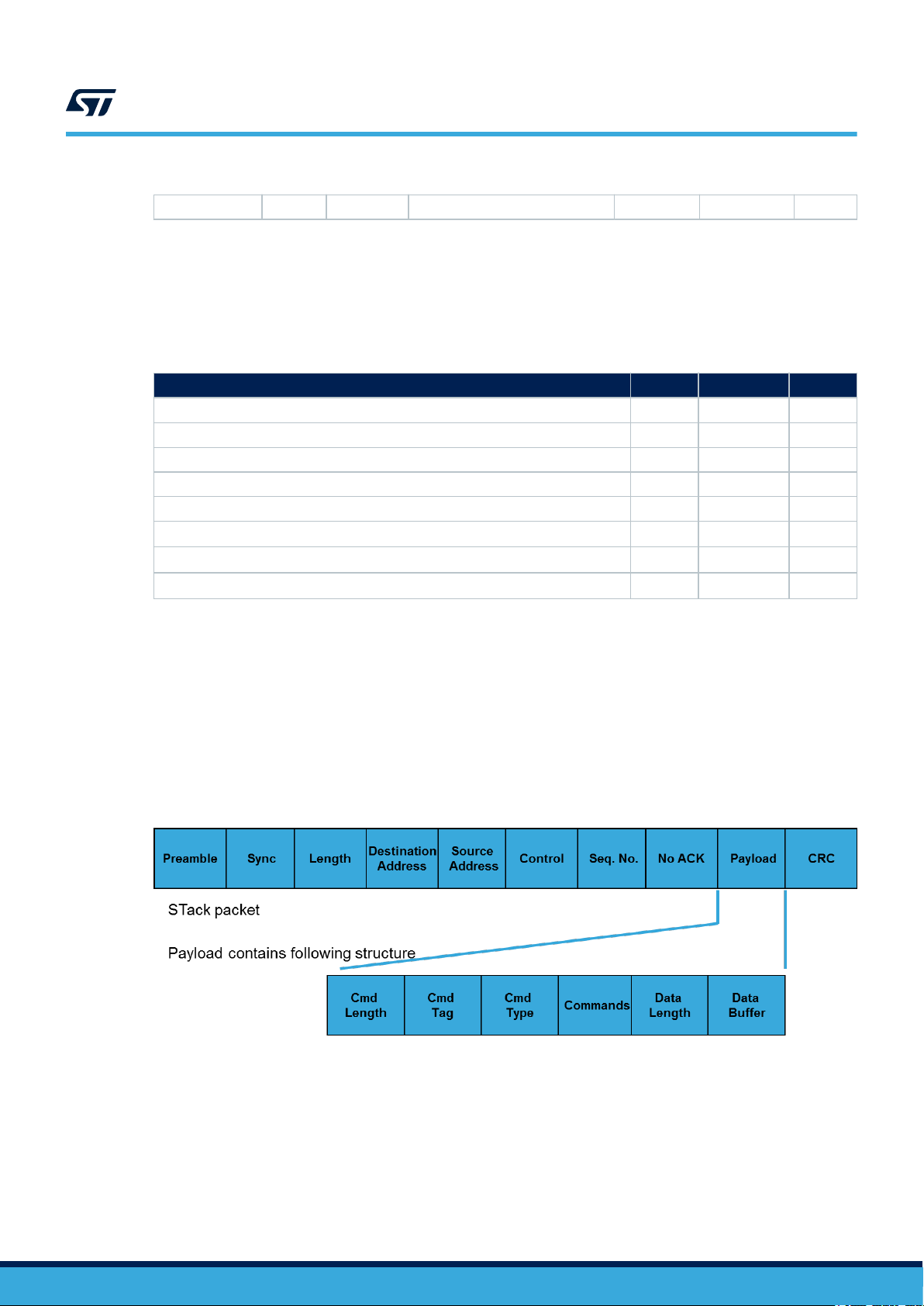
3.3 S2-LP packet handler overview
Before on-air transmission, raw data is arranged in a packet structure. S2-LP offers a highly flexible and fully
programmable packet which lets you configure the structure of the packet, the number, the type, and the
dimension of the fields inside the packet.
Through a register, the user can choose from one of the formats shown in the tables below.
Preamble Sync Length Destination address Source address Control Seq. no. No ACK Payload CRC
Table 2. Stack
Table 3. wM-Bus
UM2669 - Rev 3
Preamble Sync Payload Postamble
page 8/39
Page 9
UM2669
Transmit and receive (command and response) packet structure
Table 4. Basic
Preamble Sync Length Destination address Control Payload CRC
See S2-LP
datasheet for further details on the embedded packet handler.
Since P2P communication requires the receiving node destination address, the P2P demo is based on stack and
basic packet handlers.
Note: The wM-Bus packet format is not used in this sample demonstration.
Table 5. Packet handler feature comparison
Features Stack wM-Bus Basic
Destination address filtering Yes No Yes
Broadcast and multicast addressing Yes No Yes
Source address filtering Yes No No
Custom filtering Yes No Yes
CRC filtering Yes No Yes
LLP: automatic acknowledgment
LLP: automatic acknowledgment with piggybacking
LLP: automatic retransmission
1. Link layer protocol
(1)
(1)
(1)
Yes No No
Yes No No
Yes No No
3.4 Transmit and receive (command and response) packet structure
Command packet features:
command with data sent at the same time
•
• S2-LP can handle 65535 bytes of data
• customizable command structure
• customizable data packet maximum size
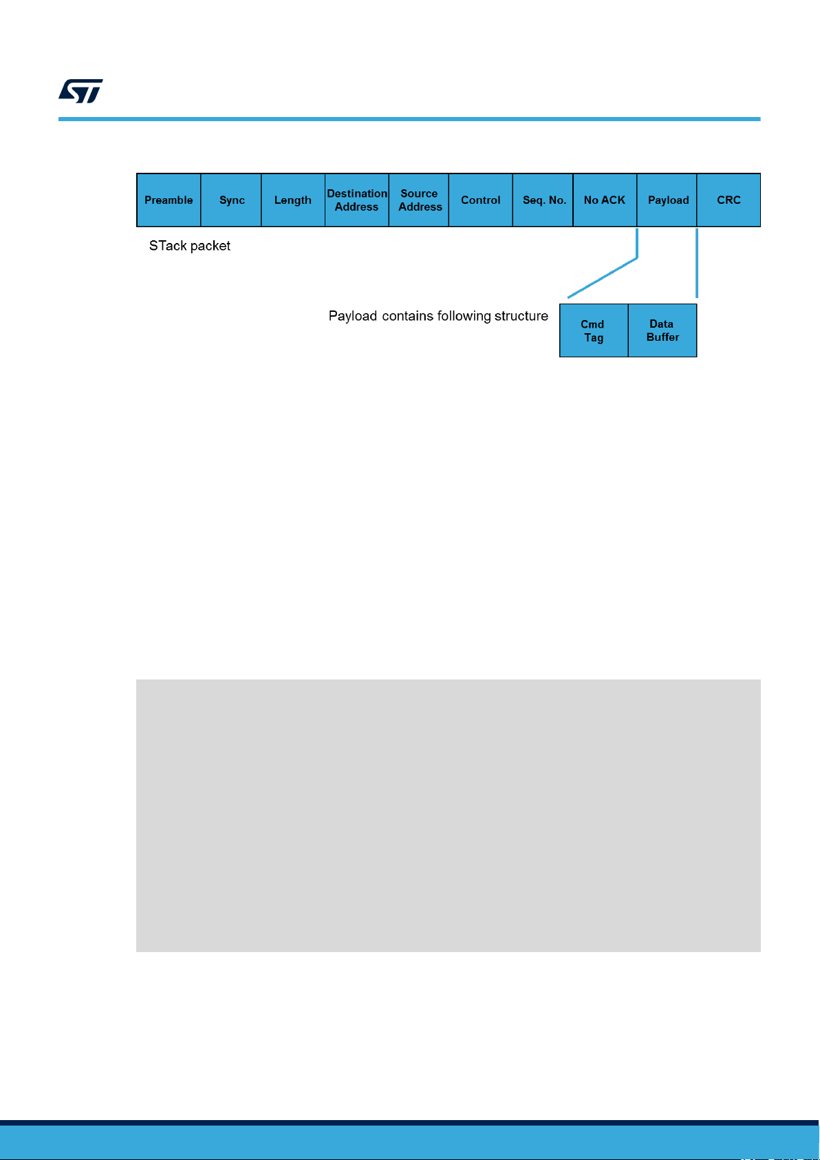
Figure 7. Command data packet structure
Response packet features:
•
data buffer is replied from the node
• tag contains the number associated with the command so the receiver can associate the response with the
specific command
UM2669 - Rev 3
page 9/39
Page 10
3.4.1 Packet field description
• Cmd Length: the basic command is 1 byte long, but you can set multiple command bytes
• Cmd T
• Cmd Type: flag to identify application level or network command
• Commands: the actual command set sent from the source to destination (it may include parameters)
• Data Length: the data packet length
• Data buffer: the actual data associated with the command
ag: a unique tag number is linked to each command issued from the node and the response must
replicate the same number
UM2669
User configuration
Figure 8. Response packet structure
3.5 User configuration
You can modify the configuration file s2868A1_conf.h (or s2868a2_conf.h, s2915a1_conf.h depending on the
expansion board) according to the application used.
3.5.1 Selecting packet handler
The user can select the desired features by setting the relevant macros:
#define USE_BASIC_PROTOCOL
#define USE_BASIC_PROTOCOL_ADDRESS /* to activate Basic protocol with Address field, to be
activated with USE_BASIC_PROTOCOL */
#define USE_RADIO_868MHz
/*...*/
#define EN_AUTOACK S_DISABLE
#define EN_PIGGYBACKING S_DISABLE
#define MAX_RETRANSMISSIONS PKT_DISABLE_RETX
#if defined(USE_STack_PROTOCOL)
//#define USE_STack_LLP /*Uncomment if LLP featured need to be used*/
#endif
#ifdef USE_BASIC_PROTOCOL
#define CSMA_ENABLE /* Comment this line to disable the CSMA */
#endif
UM2669 - Rev 3
By default, S2-LP
works with the basic packet handler.
S2-LP uses the STack packet handler only if the link layer features (such as auto-ack, piggybacking and auto-
retransmission) are defined.
page 10/39
Page 11

3.5.2 Setting low-power mode
The P2P application supports low-power mode (disabled by default). It allows the MCU to either enter stop or
sleep mode (check app_x-cube-subg2.c file for these settings).
Optional Low Power modes for the S2-LP
#if defined (USE_LOW_POWER_MODE)
//#define MCU_SLEEP_MODE
#define MCU_STOP_MODE
#endif
/*Possible Low Power modes for the S2-LP: */
//#define RF_STANDBY
//#define RF_SHUTDOWN
//#define RF_SLEEP
can also be activated (RF_* macros).
3.5.3 Setting radio configuration parameters
You can set the radio parameters in the configuration file, even though it is not recommended to change them.
/* Radio configuration parameters */
#define XTAL_OFFSET_PPM 0
#define INFINITE_TIMEOUT 0.0
UM2669
User configuration
#ifdef USE_RADIO_868MHz
#define BASE_FREQUENCY 868.0e6
#endif
#define CHANNEL_SPACE 100e3
#define CHANNEL_NUMBER 0
#define DATARATE 38400
#define FREQ_DEVIATION 20e3
#define BANDWIDTH 100E3
#define POWER_INDEX 7
#define RECEIVE_TIMEOUT 2000.0 /*change the value for required timeout
period*/
#define RSSI_THRESHOLD -120 /* Default RSSI at reception, more
than noise floor */
#define CSMA_RSSI_THRESHOLD -90 /* Higher RSSI to Transmit.
If it's lower, the Channel will be seen as busy */
/* Packet configuration parameters */
#define MODULATION_SELECT MOD_2FSK
#define POWER_DBM 12.0
3.5.4 Setting packet configuration parameters
You can set the packet configuration, even though it is not recommended to change default settings.
*/ Packet configuration parameters */
#define SYNC_WORD 0x88888888
#define LENGTH_WIDTH 7
#define CRC_MODE PKT_CRC_MODE_8BITS
#define EN_FEC S_DISABLE
#define EN_WHITENING S_ENABLE
UM2669 - Rev 3
#define PREAMBLE_LENGTH PREAMBLE_BYTE(4)
#define SYNC_LENGTH SYNC_BYTE(4)
#define CONTROL_LENGTH 0x00
#define VARIABLE_LENGTH S_ENABLE
#define EXTENDED_LENGTH_FIELD S_DISABLE
#define PREAMBLE_BYTE(v) (4*v)
#define SYNC_BYTE(v) (8*v)
page 11/39
Page 12

3.5.5 Setting node address
Node adresses parameters can be set in following section of the system setup guide.
*/ Addresses configuration parameters */
#define EN_ADDRESS S_DISABLE
#define EN_FILT_MY_ADDRESS S_DISABLE
#define EN_FILT_MULTICAST_ADDRESS S_DISABLE
#define EN_FILT_BROADCAST_ADDRESS S_DISABLE
#define EN_FILT_SOURCE_ADDRESS S_DISABLE
#define SOURCE_ADDR_MASK 0xf0
#define SOURCE_ADDR_REF 0x37
#define MULTICAST_ADDRESS 0xEE
#define BROADCAST_ADDRESS 0xFF
3.5.6 User defined commands and macros
/* User Command */
#define APPLI_CMD 0x11
#define NWK_CMD 0x22
#define LED_TOGGLE 0xff
#define ACK_OK 0x01
#define MAX_BUFFER_LEN 96
#define TIME_TO_EXIT_RX 3000
#define DELAY_RX_LED_TOGGLE 100
#define DELAY_TX_LED_GLOW 100
#define LPM_WAKEUP_TIME 100
UM2669
User configuration
UM2669 - Rev 3
page 12/39
Page 13
4 6LoWPAN applications
4.1 Contiki-NG
Contiki-NG is an OS for embedded systems providing 6LoWPAN stack on top of 802.15.4-like radio transceivers.
Contiki-NG is included as a third-party middleware library in X-CUBE-SUBG2 (starting from version 3.0.0).
The software includes samples to send messages via UDP over 6LoWP
transceiver. The key features are:
• Middleware library with Contiki-NG OS protocol stack 4.5
• Support for mesh networking technology via the standard RPL protocol (lite, with default support for nonstoring mode, and classic versions are available)
• Sample applications (such as UPD Client and UDP Server, Serial Sniffer and RPL Border Router)
• Nodes can be monitored and controlled using the embedded Serial Shell and the flexible logging system
• Link-Layer encryption using AES128
• 802.15.4 MAC ACK packets
• Optional end-to-end security using TinyDTLS
• Samples available for NUCLEO-F401RE and NUCLEO-L152RE
• Easy portability across different MCU families, thanks to STM32Cube
• Free and user-friendly license terms
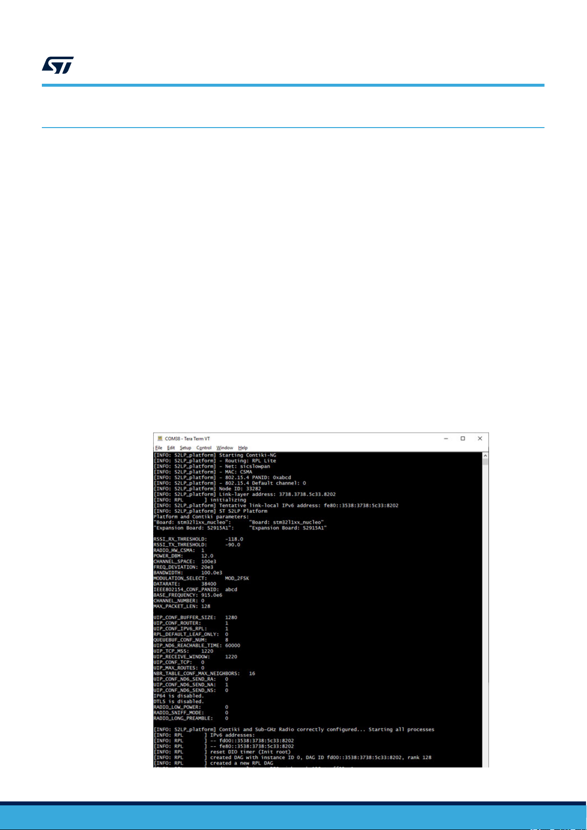
At boot time, the firmware based on Contiki-NG prints a set of information regarding the system identification and
chosen parameters as shown below.
UM2669
6LoWPAN applications
AN, using the S2-LP sub-1GHz radio
Figure 9. System configuration and parameters print at boot time (example)
UM2669 - Rev 3
page 13/39
Page 14
For the Contiki-NG firmware, interaction with a Serial Terminal utility is available. The utility has to be configured
with the following parameters: 115200 bps, 8 bit, No Parity
, 1 stop bit.
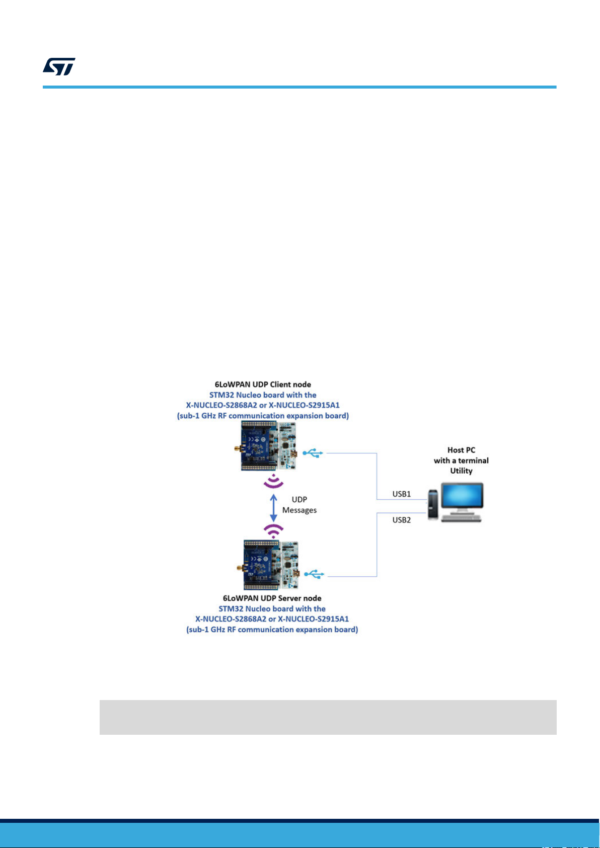
4.1.1 UDP Client and UDP Server sample application overview
UDP Client and UDP Server sample application workflow can be summarized as follows:
1. the UDP Client node periodically creates a message, prints it on the terminal window along with the IPv6
address of the UDP Server it is going to transmit to (usually the RPL root) and sends it via UDP packets over
the air
the UDP Server node is indefinitely listening for UDP packets, until it receives the data packets from the
2.
UDP Client node
3. the UDP Server node sends back a UDP packet with a reply and outputs the received message packet
content in the terminal window
4. the UDP Client node receives the answer from the UDP Server and prints the received message in the
terminal window
If more than one UDP Client node is used, the UDP Server receives messages from and send back replies to all
of them.
By default, the UDP Server firmware is setup as root of the RPL tree and by default the UDP Client firmware
sends messages to the IPv6 address of the RPL root (i.e. the root of the tree is also the UDP Server, no additional
configuration is required).
UM2669
Contiki-NG
Figure 10. UDP Client and UDP Server node communication with a PC
UM2669 - Rev 3
Contiki-NG provides a flexible log system that can be controlled using the Serial Shell (enabled by default).
The UDP Client and UDP Server firmware starts with a verbose log level for RPL, MAC and FRAMER layers, as
per the following configuration (that can be found in the project-conf.h file at application level):
#define LOG_CONF_LEVEL_MAC LOG_LEVEL_DBG
#define LOG_CONF_LEVEL_RPL LOG_LEVEL_DBG
#define LOG_CONF_LEVEL_FRAMER LOG_LEVEL_ERR
The following figures show the terminal outputs.
page 14/39
Page 15

Figure 11. UDP Server console output
UM2669
Contiki-NG
Figure 12. UDP Client console output
This logging level can be useful to debug a new developed application. The built-in Shell provides a list of useful
commands that can be listed by selecting the
[help] command as shown below.
UM2669 - Rev 3
page 15/39
Page 16

UM2669
Contiki-NG
Figure 13. List of commands available in the Serial Shell
Different commands are available to show routes and neighbors, and to ping other nodes or to control and
manipulate the status of the RPL tree.
The log level can be controlled as well: for any layer/module, a specific log level can be set from 0 up to the level
set at compilation time for each layer/module. For example, the log all 0 command disables the messages
from lower layers (FRAMER, MAC and RPL in this case), leaving only the Applicative messages as shown in the
following figures.
Figure 14. Shell before and after
log all 0 command
UM2669 - Rev 3
page 16/39
Page 17

UM2669
Serial Sniffer sample application overview
Figure 15. UDP Client (left) and UDP Server (right) console output after
4.2 Serial Sniffer sample application overview
The Serial Sniffer application allows the user to capture RF packets and send them to an analysis tool (like
Wireshark) to see and analyze the messages exchanged among the nodes in a 6LoWP
To be connected to Wireshark, the Serial Sniffer firmware needs some tools, to be launched on a host PC, located
in the X-CUBE-SUBG2 Utilities/PC_Software/SerialSniffer folder. A pre-requisite for using the tools is the use of
Perl and, of course, Wireshark.
If running under Microsoft Windows, another pre-requisite is the Cygwin emulator of the Linux environment (in this
case, Perl can be installed using the Cygwin setup).
log all 0 command
AN network.
4.2.1 How to use the Serial Sniffer application under Linux
Step 1. Compile serialdump-linux utility from X-CUBE-SUBG2 package.
cd Utilities/PC_Software/SerialSniffer/serialdump-src
make
(or gcc –o serialdump-linux serialdump.c)
mv serialdump-linux ..
cd ..
Step 2. From the Serial Snif
fer folder, run the following command chain (one line command made up of three
commands in line, separated by “|”):
> sudo serialdump-linux -b115200 /dev/ttyACMx | ./convert-to-binary |wireshark -k
-i -
4.2.2 How to use the Serial Sniffer application under Windows
Step 1. Run Cygwin as administrator
Step 2. The serialdup-windows.exe utility is provided pre-compiled, but if you need to recompile it, from the
X-CUBE-SUBG2 package root, run:
cd Utilities/PC_Software/SerialSniffer/serialdump-src
make
(or gcc –o serialdump-windows.exe serialdump.c)
mv serialdump-windows.exe ..
cd ..
UM2669 - Rev 3
page 17/39
Page 18

Step 3. Run the following command chain (one line command made up of three commands in line, separated
by “|”):
>serialdump-windows.exe -b115200 /dev/ttySz | ./convert-to-binary |wireshark.exe -k
-i -
4.2.3 Important additional information
• In the commands mentioned in the previous sections, mind the trailing dash (-): it is mandatory
The ttySz / ttyACMx numbers depend on the device enumeration of the STM32 Nucleo development
•
board running the Serial Sniffer firmware: to this aim, you can use the auto-completion tab under Linux and
Cygwin
• It is mandatory to invoke the above commands from the Serial Sniffer folder (actually, the header.pcap file
should be in the same folder of the convert-to-binary script)
• Wireshark application is required: it is recommended to use the application latest version to have the
state-of-the-art protocol dissectors
• In the above commands, Wireshark is supposed to be in the system shell path, otherwise you must provide
the full command path or create a proper link
• Under Windows, if you need to use the full path for wireshark.exe and this contains spaces, use '' as escape
character before spaces and parenthesis
• Serial Sniffer firmware must be compiled with the same radio (channel, modulation, etc.) settings as the
network under investigation
• On some Windows PCs, you may need to hardcode the baudrate (115200) in the serialdump.c code and
recompile
• Also, on some Windows PCs, if you get the “could not get options: Invalid argument” error
message, it is required to open a terminal utility (like Tera Term) on the console of the Serial Sniffer node,
reset it (see the figure below), close the terminal and then run the command chain again in the Cygwin shell.
UM2669
Serial Sniffer sample application overview
Figure 16. Serial Sniffer output in Tera Term
The Serial Sniffer firmware uses the User Button on the node to start/stop acquisition. It boots up in stop mode.
This can be seen on the console (as shown in the figures above and below).
UM2669 - Rev 3
page 18/39
Page 19

UM2669
Serial Sniffer sample application overview
Figure 17. Cygwin shell: command line to interact with Serial Sniffer
The sequence of commands will launch the Wireshark application through which the RF packets can be seen,
analyzed and saved.
UM2669 - Rev 3
page 19/39
Page 20

UM2669
Serial Sniffer sample application overview
Important:
In X-CUBE-SUBG2, the default configuration of the Contiki-NG based application comes with Link Layer security enabled. In
this case, the Serial Sniffer captures RF packets and shows them encrypted in W
Figure 18. Message exchange flow between UDP Server and UDP Client (capture of Link Layer encrypted
packets)
ireshark.
UM2669 - Rev 3
Link Layer security can be disabled by editing the contiki-conf.h file (located in the Inc/ folder of each application)
for all the network node (UDP Client and UDP Server in this case) firmware and changing the value of the
following macro from:
/* Enable Link Layer security */
#define LLSEC802154_CONF_ENABLED 1
to:
#define LLSEC802154_CONF_ENABLED 0
page 20/39
Page 21

UM2669
Border Router sample application overview
The firmware applications must now be recompiled and re-flashed on the nodes.
By disabling the Link Layer security
Wireshark.
Figure 19. Message exchange flow between UDP Server and UDP Client (capture of Link Layer plain text
, the UDP messages exchanged by the two applications are visible in clear in
packets)
4.3 Border Router sample application overview
This example lets the user configure an “RPL Border Router” node between a 6LoWPAN network and a host
system, such as a PC, typically connected to the Wide Area Network. The following sections describe how to
integrate this border router into a system.
4.3.1 System overview
The Border Router application system architecture consists of:
an IPv6 host device that runs the client application (e.g., a web browser) over an IPv6-based protocol stack.
•
This device can also provide Wide Area Network connectivity
UM2669 - Rev 3
page 21/39
Page 22

UM2669
Border Router sample application overview
• an edge (or border) router device that creates a 6LowPAN network and is connected to the wireless nodes
on one side and to the IPv6 host on the other
board with a sub-1 GHz RF communication expansion board. To generate the firmware for this device, you
have to select the “Border Router” project folder and compile the project with one of the supported IDEs or
use the sample binary firmware provided in the same project folder
• a low-power wireless node connected to the 6LoWPAN network. In our case, this device is an STM32
Nucleo development board with a sub-1 GHz RF communication expansion board. To generate the firmware
for this device, you have to select the “UDP Client” project folder and compile the project with one of the
supported IDEs or use the sample binary firmware provided in the same project folder.
Figure 20. System architecture for Border Router application
. In our case, this device is an STM32 Nucleo development
4.3.2 IPv6 host setup
4.3.2.1 IPv6 packet bridging - Windows setup
This setup information is for a Windows (version 7 and later) host PC; the host side implements a standard IPv6based networking stack. The “wpcapslip6” application exchanges IPv6 packets over the serial line between the
host PC stack and the border router IPv6 stack.
UM2669 - Rev 3
page 22/39
Page 23

UM2669
Border Router sample application overview
Step 1. Install the Microsoft loopback network adapter by selecting
Manager.
Figure 21. Adding the network adapter in Windows
[Add legacy hardware] in the Device
Step 2. Follow the Installer instructions by selecting the following entries:
[Add legacy
hardware]>[Next]>[Install the hardware manually selected from a list]>[Next]>[Select Networks
Adapters]>[Next]>[Select Microsoft from the Manufacturer list then Microsoft KM-TEST
Loopback Adapter from the Network Adapter list ]>[Next] → then finish the installation by clicking
[Next] again.
Step 3. Reboot your PC.
Step 4. Install the WinPcaP Windows packet capture library. The installer and setup information can be found
at https://www.winpcap.org/install/
UM2669 - Rev 3
page 23/39
Page 24

UM2669
Border Router sample application overview
Step 5. Launch the Command prompt shell and run the wpcaslip6 utility with a node running the Border Router
firmware connected to the host PC.
cd [X-CUBE-SUBG2]\Utilities\PC_Software\wpcapslip6
wpcapslip6.exe –s /dev/ttyS14 –b aaaa:: -a aaaa::1/128 [addr]
ou can obtain the serial device number to be used (in this example, “ttyS14”) by looking for the
Y
Virtual COM Port number associated with the STM32 Nucleo board. The value to use when running the
“wpcapslip6.exe” command is the COM Port number minus 1. In our example, the COM Port number is
15 (hence the “ttyS14” device parameter).
Figure 22. STM32 Nucleo board virtual COM Port value
The [addr] parameter is the MAC address of the local network adapter (Microsoft KM-TEST Loopback
Adapter). This information can be found by launching the ipconfig /all command shown below
.
Figure 23. Reading the MAC address of the Microsoft KM-TEST loopback adapter
UM2669 - Rev 3
page 24/39
Page 25

Figure 24. wpcapslip6 utility terminal window (snapshot)
4.3.2.2 IPv6 packet bridging - Linux setup
This setup information is for a Linux host PC; the host side implements a standard IPv6-based networking stack.
Note:
If you use the same Linux PC for firmware development, note that only the projects provided with the
STM32CubeIDE are available for this platform.
Step 1. Install the tunslip6 software module to exchange IPv6 packets over the serial line between the host PC
stack and the border router IPv6 stack. To compile it, from the root directory of the X-CUBE-SUBG2
package, run:
UM2669
Border Router sample application overview
cd Utilities/PC_Software/Contiki-NG/serial-io
make tunslip6
Step 2. Assuming that the border router device set up in the previous section is connected to the Linux host,
launch the tunslip6 application by providing the parameter for the virtual communication port to which
the border router device is connected (located in “/dev/ttyACMx” where “x” is the corresponding port
number, here we assume x=0):
sudo ./tunslip6 –s /dev/ttyACM0 aaaa::1/64
This command creates a new virtual interface in the Linux host, called “tun0”.
UM2669 - Rev 3
page 25/39
Page 26

UM2669
Border Router sample application overview
Step 3. Reset the STM32 Nucleo board on which the border router is implemented by pressing the black
[RESET] button which triggers the system initialization and the exchange of configuration information
with the tunslip6 application. A snapshot of the terminal running the tunslip6 utility is shown below
Figure 25. tunslip6 terminal window (snapshot)
.
4.3.2.3 IPv6 Host setup troubleshooting
• The tunslip6 application does not work properly with Ubuntu kernel 3.13.0-65-generic (part of the Ubuntu
14.04 L
TS)
• The Cygwin library used by the wpcapslip6 tool limits the “/dev/ttyS*” number to 100. If you have a device
with a higher number, either:
1. a. Recompile Cygwin DLL library as suggested at
2. Remove allocated COM ports (you can find some help at http://superuser.com/questions/408976/
howdo-i-clean-up-com-ports-in-use)
• Disable your firewall
• Ensure IPv6 is enabled:
1. in the properties of the Loopback Adapter
2. by setting (if present) registry key HKEY_LOCAL_MACHINE\SYSTEM\CurrentControlSet\services
\TCPIP6\Parameters\DisabledComponents to the value 0x8E
3. You may need to change the default name of the network connection associated with the Microsoft
loopback adapter to a name that does not contain spaces
• Under Windows the functionality of wpcapslip6 utility depends on the level of administrative rights of the user
4.3.3 Contiki server access and connectivity test
Step 1. Open a web browser to access the Contiki-NG border router web server
neighbors and routes.
, which returns the RPL
UM2669 - Rev 3
page 26/39
Page 27

UM2669
Border Router sample application overview
Step 2. Access it via the first address listed in the “wpcapslip6” (Windows) or “tunslip6” (Linux) terminal
window
The following figure shows the web browser page after inserting the IPv6 address of the server in
the URL (the IPv6 address must be enclosed in square brackets). Assuming that a wireless node is
running, the IPv6 address of the wireless node should be in the “Neighbors” list.
, after the “Server IPv6 addresses:” line.
Figure 26. Contiki-NG border router web server
Step 3. Run a simple ping6 command to check the end-to-end IPv6 connectivity between the Linux IPv6 host
and the wireless sensor node using the full 128-bit IPv6 address in the “Routes” list. In this specific
example, the ping6 command (or “ping -6” in Windows) is ping6 aaaa::3532:3230:6b36:700d.
The following figure is a snapshot of the ping6 command execution showing the ping from the Linux
host replied by the remote wireless sensor node.
Figure 27. ping6 command window snapshot
UM2669 - Rev 3
page 27/39
Page 28
UM2669
Border Router sample application overview
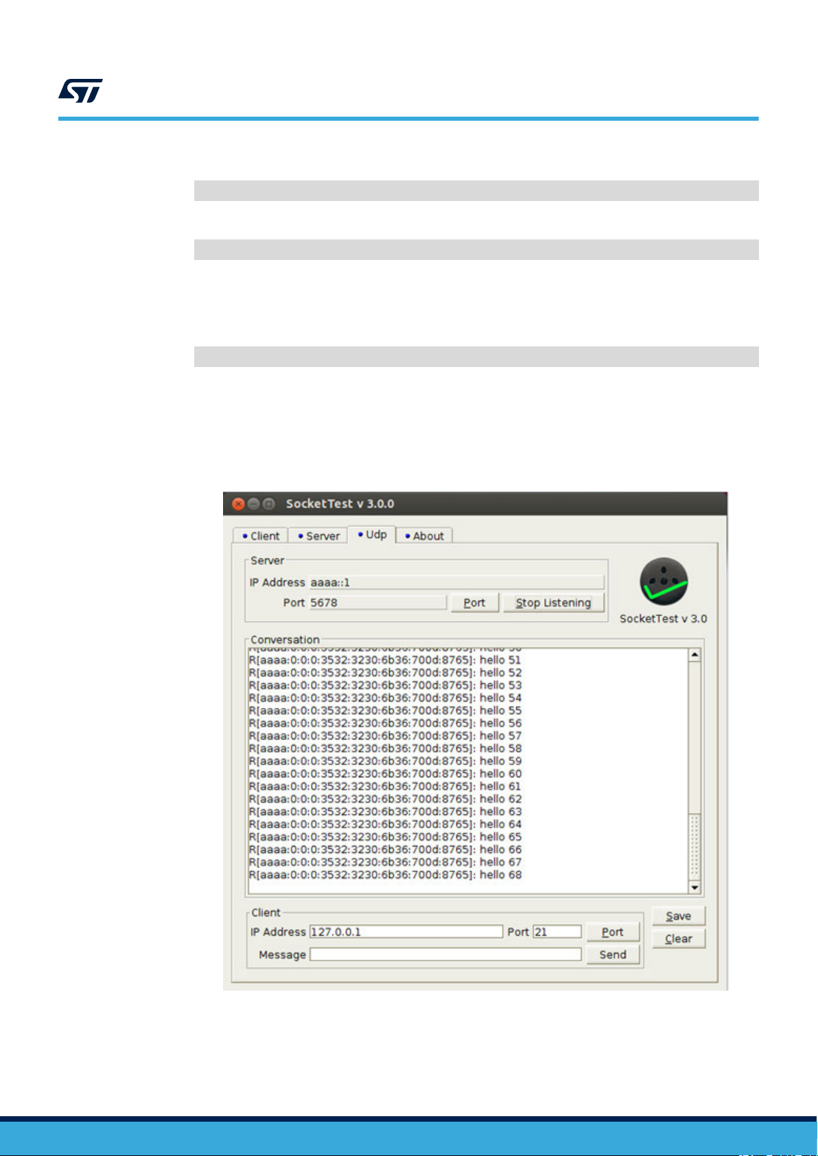
Step 4. T
o perform another test, recompile the UDP Client application by changing the macro
#define BORDER_ROUTER_SCENARIO 0
to
#define BORDER_ROUTER_SCENARIO 1
in the udp-client.c file.
By doing this, the UDP Client will not send the packets to the address of the root of the RPL tree, like
in the default configuration (this setup is thought to work with the UDP Server firmware), but to another
hardcoded address specified in the code, i.e.
#define BORDER_ROUTER_SCENARIO_ADDRESS "aaaa::1"
that must match the address passed to tunslip6 or wpcapslip6 tools. This address is the one taken
by the virtual network interface of the host PC, so, by running any UDP Server application on it and
setting it to listen to proper address and port, you will be able to receive the UDP messages sent by the
UDP Client node on the host PC (as they are routed from the wireless 6LoWP
AN network to the IPv6
protocol stack of the PC by the Border Router firmware) as shown below.
Figure 28. UDP Server running behind the Border Router
UM2669 - Rev 3
page 28/39
Page 29

5 System setup
5.1 Hardware description
5.1.1 STM32 Nucleo
STM32 Nucleo development boards provide an af
prototypes with any STM32 microcontroller line.
The Arduino™ connectivity support and ST morpho connectors make it easy to expand the functionality of the
STM32 Nucleo open development platform with a wide range of specialized expansion boards to choose from.
The STM32 Nucleo board does not require separate probes as it integrates the ST-LINK/V2-1 debugger/
programmer.
The STM32 Nucleo board comes with the comprehensive STM32 software HAL library together with various
packaged software examples for different IDEs (IAR EWARM, Keil MDK-ARM, STM32CubeIDE, mbed and GCC/
LLVM).
All STM32 Nucleo users have free access to the mbed online resources (compiler, C/C++ SDK and developer
community) at www.mbed.org to easily build complete applications.
UM2669
System setup
fordable and flexible way for users to test solutions and build
Figure 29. STM32 Nucleo board
Information regarding the STM32 Nucleo board is available at www
5.1.2 X-NUCLEO-S2868A1 expansion board
The X-NUCLEO-S2868A1 expansion board is based on the S2-LP radio and operates in the 868 MHz ISM
frequency band.
The expansion board is compatible with ST morpho and Arduino UNO R3 connectors.
The X-NUCLEO-S2868A1 interfaces with the STM32 Nucleo microcontroller via SPI connections and GPIO pins.
Y
ou can change some of the GPIOs by mounting or removing the resistors.
UM2669 - Rev 3
.st.com/stm32nucleo
page 29/39
Page 30

Figure 30. X-NUCLEO-S2868A1 expansion board
UM2669
Hardware description
5.1.3 X-NUCLEO-S2868A2 and X-NUCLEO-S2915A1 expansion boards
The X-NUCLEO-S2868A2 expansion board is based on the S2-LP radio and operates in the 868 MHz ISM
frequency band.
The X-NUCLEO-S2915A1 expansion board is based on the S2-LP radio and operates in the 915 MHz ISM
frequency band.
The expansion boards are compatible with ST morpho and Arduino UNO R3 connectors, and interface with the
STM32 Nucleo microcontroller via SPI connections and GPIO pins.
Y
ou can change some of the GPIOs by mounting or removing the resistors.
Figure 31. X-NUCLEO-S2868A2 expansion board
UM2669 - Rev 3
page 30/39
Page 31

Figure 32. X-NUCLEO-S2915A1 expansion board
UM2669
Software description
5.2 Software description
To use STM32 Nucleo development boards with the X-NUCLEO-S2868A1, X-NUCLEO-S2868A2, X-NUCLEO-
S2915A1 expansion boards, the following software specification are required:
• X-CUBE-SUBG2 expansion for STM32Cube. The X-CUBE-SUBG2 firmware and related documentation is
available on www
• Development tool-chain and Compiler supported by the STM32Cube expansion software:
– IAR Embedded Workbench for ARM® toolchain + ST-LINK
– RealView Microcontroller Development Kit (MDK-ARM-STR) toolchain + ST-LINK
– STM32CubeIDE + ST-LINK
.st.com.
5.3 Hardware setup
The following hardware components are required:
•
an STM32 Nucleo development board (order code: NUCLEO-F401RE, NUCLEO-L152RE or NUCLEO-
L053R8)
• an S2-LP expansion board (order code: X-NUCLEO-S2868A1, X-NUCLEO-S2868A2 or X-NUCLEO-
S2915A1)
• a USB type A to Mini-B USB cable to connect the STM32 Nucleo to the PC
5.4 Board setup
Step 1. Check that the jumper on J1 is connected to provide the required voltage to the board devices
UM2669 - Rev 3
page 31/39
Page 32

UM2669
Board setup
Step 2. Connect the X-NUCLEO-S2868A1, X-NUCLEO-S2868A2 or X-NUCLEO-S2915A1 to the STM32
Nucleo
Figure 33. X-NUCLEO-S2868A1 expansion board plugged onto an STM32 Nucleo board
Step 3. Power the STM32 Nucleo
board using the Mini-B USB cable
Step 4. Program the firmware in the STM32 on the Nucleo development board using the firmware sample
provided
Step 5. Press the reset button on the STM32 Nucleo board
The demonstration kit is ready-to-use
UM2669 - Rev 3
page 32/39
Page 33

6 References
Freely available on www.st.com:
1. STM32 Nucleo development board datasheet
2.
UM2405: Getting started with the X-NUCLEO-S2868A1 Sub-1 GHz 868 MHz RF expansion board based on
S2-LP radio for STM32 Nucleo
3. UM2638: Getting started with the X-NUCLEO-S2868A2 Sub-1 GHz 868 MHz RF expansion board based on
S2-LP radio for STM32 Nucleo
4. UM2641: Getting started with the X-NUCLEO-S2915A1 Sub-1 GHz 915 MHz RF expansion board based on
S2-LP radio for STM32 Nucleo
5. S2-LP datasheet
UM2669
References
UM2669 - Rev 3
page 33/39
Page 34

Revision history
Date Revision Changes
12-Dec-2019 1 Initial release.
14-Feb-2020 2
02-Dec-2020 3
UM2669
T
able 6. Document revision history
Updated Figure 1. X-CUBE-SUBG2 software architecture and Section 4 References.
Added Section 3.6.3 X-NUCLEO-S2868A2 and X-NUCLEO-S2915A1 expansion boards.
Added X-NUCLEO-S2868A2 and X-NUCLEO-S2915A1 expansion board compatibility information.
Updated Section 1 Acronyms and abbreviations, Section 2.1 Overview, Section 2.2 Architecture
and Section 2.3 Folder structure.
Added Section 4 6LoWP
and UDP Server sample application overview, Section 4.2 Serial Sniffer sample application
overview, Section 4.2.1 How to use the Serial Sniffer application under Linux, Section 4.2.2 How
to use the Serial Sniffer application under Windows, Section 4.2.3 Important additional
information, Section 4.3 Border Router sample application overview, Section 4.3.1 System
overview, Section 4.3.2 IPv6 host setup, Section 4.3.2.1 IPv6 packet bridging - Windows
setup, Section 4.3.2.2 IPv6 packet bridging - Linux setup, Section 4.3.2.3 IPv6 Host setup
troubleshooting and Section 4.3.3 Contiki server access and connectivity test.
AN applications, Section 4.1 Contiki-NG, Section 4.1.1 UDP Client
UM2669 - Rev 3
page 34/39
Page 35

UM2669
Contents
Contents
1 Acronyms and abbreviations ......................................................2
2 X-CUBE-SUBG2 software expansion for STM32Cube ...............................3
2.1 Overview .....................................................................3
2.2 Architecture ...................................................................3
2.3 Folder structure ................................................................5
2.4 APIs .........................................................................5
3 Point-to-Point (P2P) demo firmware description ....................................6
3.1 P2P application details ..........................................................6
3.2 Application state diagram........................................................6
3.3 S2-LP packet handler overview...................................................8
3.4 T
ransmit and receive (command and response) packet structure ......................9
3.4.1 Packet field description ...................................................10
3.5 User configuration.............................................................10
3.5.1 Selecting packet handler..................................................10
3.5.2 Setting low-power mode ..................................................11
3.5.3 Setting radio configuration parameters .......................................11
3.5.4 Setting packet configuration parameters ...................................... 11
3.5.5 Setting node address ....................................................12
3.5.6 User defined commands and macros ........................................12
4 6LoWPAN applications ...........................................................13
4.1 Contiki-NG ...................................................................13
4.1.1 UDP Client and UDP Server sample application overview ........................14
4.2 Serial Sniffer sample application overview.........................................17
4.2.1 How to use the Serial Sniffer application under Linux ............................17
4.2.2 How to use the Serial Sniffer application under Windows .........................17
4.2.3 Important additional information ............................................18
4.3 Border Router sample application overview........................................21
4.3.1 System overview........................................................21
4.3.2 IPv6 host setup .........................................................22
4.3.3 Contiki server access and connectivity test....................................26
UM2669 - Rev 3
page 35/39
Page 36

UM2669
Contents
5 System setup.....................................................................29
5.1 Hardware description ..........................................................29
5.1.1 STM32 Nucleo .........................................................29
5.1.2 X-NUCLEO-S2868A1 expansion board.......................................29
5.1.3 X-NUCLEO-S2868A2 and X-NUCLEO-S2915A1 expansion boards.................30
5.2 Software description ...........................................................31
5.3 Hardware setup...............................................................31
5.4 Board setup ..................................................................31
6 References .......................................................................33
Revision history .......................................................................34
UM2669 - Rev 3
page 36/39
Page 37

UM2669
List of figures
List of figures
Figure 1. X-CUBE-SUBG2 software architecture ...................................................4
Figure 2. X-CUBE-SUBG2 package folder structure .................................................5
Figure 3. X-NUCLEO-S2868A1 plus STM32 Nucleo used as a node (transmitter/receiver) in P2P communication ...... 6
Figure 4. Application state diagram when Node 1 user button is pressed ...................................7
Figure 5. Application state diagram when Node 2 user button is pressed ...................................7
Figure 6. Application state diagram (low-power mode): data communication transmit and receive states .............8
Figure 7. Command data packet structure ........................................................9
Figure 8. Response packet structure ........................................................... 10
Figure 9. System configuration and parameters print at boot time (example) ............................... 13
Figure 10. UDP Client and UDP Server node communication with a PC ................................... 14
Figure 1
Figure 12. UDP Client console output ...........................................................15
Figure 13. List of commands available in the Serial Shell.............................................. 16
Figure 14. Shell before and after log all 0 command ................................................. 16
Figure 15. UDP Client (left) and UDP Server (right) console output after log all 0 command ...................... 17
Figure 16. Serial Sniffer output in Tera Term ...................................................... 18
Figure 17. Cygwin shell: command line to interact with Serial Sniffer...................................... 19
Figure 18. Message exchange flow between UDP Server and UDP Client (capture of Link Layer encrypted packets) .... 20
Figure 19. Message exchange flow between UDP Server and UDP Client (capture of Link Layer plain text packets) ..... 21
Figure 20. System architecture for Border Router application ........................................... 22
Figure 21. Adding the network adapter in Windows.................................................. 23
Figure 22. STM32 Nucleo board virtual COM Port value .............................................. 24
Figure 23. Reading the MAC address of the Microsoft KM-TEST loopback adapter............................ 24
Figure 24. wpcapslip6 utility terminal window (snapshot) ..............................................25
Figure 25. tunslip6 terminal window (snapshot) ....................................................26
Figure 26. Contiki-NG border router web server .................................................... 27
Figure 27. ping6 command window snapshot...................................................... 27
Figure 28. UDP Server running behind the Border Router ............................................. 28
Figure 29. STM32 Nucleo board .............................................................. 29
Figure 30. X-NUCLEO-S2868A1 expansion board ..................................................30
Figure 31. X-NUCLEO-S2868A2 expansion board ..................................................30
Figure 32. X-NUCLEO-S2915A1 expansion board ..................................................31
Figure 33. X-NUCLEO-S2868A1 expansion board plugged onto an STM32 Nucleo board ....................... 32
1. UDP Server console output .......................................................... 15
UM2669 - Rev 3
page 37/39
Page 38

UM2669
List of tables
List of tables
T
able 1. List of acronyms ....................................................................2
Table 2. Stack ............................................................................8
Table 3. wM-Bus ..........................................................................8
Table 4. Basic ............................................................................ 9
Table 5. Packet handler feature comparison .......................................................9
Table 6. Document revision history .............................................................34
UM2669 - Rev 3
page 38/39
Page 39

UM2669
IMPORTANT NOTICE – PLEASE READ CAREFULLY
STMicroelectronics NV and its subsidiaries (“ST”) reserve the right to make changes, corrections, enhancements, modifications, and improvements to ST
products and/or to this document at any time without notice. Purchasers should obtain the latest relevant information on ST products before placing orders. ST
products are sold pursuant to ST’
Purchasers are solely responsible for the choice, selection, and use of ST products and ST assumes no liability for application assistance or the design of
Purchasers’ products.
No license, express or implied, to any intellectual property right is granted by ST herein.
Resale of ST products with provisions different from the information set forth herein shall void any warranty granted by ST for such product.
ST and the ST logo are trademarks of ST. For additional information about ST trademarks, please refer to www
names are the property of their respective owners.
Information in this document supersedes and replaces information previously supplied in any prior versions of this document.
s terms and conditions of sale in place at the time of order acknowledgement.
.st.com/trademarks. All other product or service
© 2020 STMicroelectronics – All rights reserved
UM2669 - Rev 3
page 39/39
 Loading...