

Page 1
UM2262
User manual
Getting started with the X-CUBE-SBSFU
STM32Cube Expansion Package
Introduction
This user manual describes how to get started with the X-CUBE-SBSFU STM32Cube
Expansion Package.
The X-CUBE-SBSFU Secure Boot and Secure Firmware Update
of the STM32 microcontroller built-in program with new firmware versions, adding new
features and correcting potential issues. The update process is performed in a secure way
to prevent unauthorized updates and access to confidential on-device data.
The Secure Boot (Root of Trust services) is a
system reset, that checks STM32 static protections, activates STM32 runtime protections,
and then verifies the authenticity and integrity of user application code before every
execution to ensure that invalid or malicious code cannot be run.
The Secure Firmware Update application receives the
with the Ymodem protocol, checks its authenticity, and checks the integrity of the code
before installing it. The firmware update is done on the complete firmware image, or only on
a portion of the firmware image. Examples are provided for single-slot configuration to
maximize firmware image size, and for dual-slot configuration to ensure safe image
installation and enable over-the-air firmware update capability commonly used in IoT
devices. For a complex system, the firmware image configuration can be extended up to
three images. Examples can be configured to use asymmetric or symmetric cryptographic
schemes with or without firmware encryption.
The secure key management services provide cryptog
application through the PKCS #11 APIs (KEY ID-based APIs) that are executed inside a
protected and isolated environment. User application keys are stored in the protected and
isolated environment for their secured update: authenticity check, data decryption, and data
integrity check.
STSAFE-A110 is a tamper-resista
certified) used to host X509 certificates and keys and perform verifications that are used for
firmware image authentication during Secure Boot and Secure Firmware Update
procedures.
nt secure element (Hardware Common Criteria EAL5+
n immutable code, always executed after a
firmware image via a UART interface
raphic services to the user
solution allows the update
X-CUBE-SBSFU is built on top of STM32Cube software technology
across different STM32 microcontrollers easy. It is provided as a reference code to
demonstrate the best use of STM32 security protections.
X-CUBE-SBSFU is classified ECCN 5D002.
October 2020 UM2262 Rev 8 1/103
, making the portability
www.st.com
1
Page 2

Contents UM2262
Contents
1 General information . . . . . . . . . . . . . . . . . . . . . . . . . . . . . . . . . . . . . . . . . 9
1.1 Terms and definitions . . . . . . . . . . . . . . . . . . . . . . . . . . . . . . . . . . . . . . . . . 9
1.2 References . . . . . . . . . . . . . . . . . . . . . . . . . . . . . . . . . . . . . . . . . . . . . . . . .11
2 STM32Cube overview . . . . . . . . . . . . . . . . . . . . . . . . . . . . . . . . . . . . . . . 12
3 Secure Boot and Secure Firmware Update (SBSFU) . . . . . . . . . . . . . . 14
3.1 Product security introduction . . . . . . . . . . . . . . . . . . . . . . . . . . . . . . . . . . 14
3.2 Secure Boot . . . . . . . . . . . . . . . . . . . . . . . . . . . . . . . . . . . . . . . . . . . . . . . 14
3.3 Secure Firmware Update . . . . . . . . . . . . . . . . . . . . . . . . . . . . . . . . . . . . . 15
3.4 Cryptography operations . . . . . . . . . . . . . . . . . . . . . . . . . . . . . . . . . . . . . 16
4 Key management services . . . . . . . . . . . . . . . . . . . . . . . . . . . . . . . . . . . 18
5 Protection measures and security strategy . . . . . . . . . . . . . . . . . . . . . 20
5.1 STM32L4 Series and STM32L0 Series . . . . . . . . . . . . . . . . . . . . . . . . . . 21
5.2 STM32F4 Series, STM32F7 Series, and STM32L1 Series . . . . . . . . . . . 24
5.3 STM32G0 Series, STM32G4 Series, and STM32H7 Series . . . . . . . . . . 26
5.4 STM32WB Series . . . . . . . . . . . . . . . . . . . . . . . . . . . . . . . . . . . . . . . . . . . 30
5.5 STM32L4 Series combined with STSAFE-A110 . . . . . . . . . . . . . . . . . . . 32
6 Package description . . . . . . . . . . . . . . . . . . . . . . . . . . . . . . . . . . . . . . . . 35
6.1 General description . . . . . . . . . . . . . . . . . . . . . . . . . . . . . . . . . . . . . . . . . 35
6.2 Architecture . . . . . . . . . . . . . . . . . . . . . . . . . . . . . . . . . . . . . . . . . . . . . . . 37
6.2.1 STM32CubeHAL . . . . . . . . . . . . . . . . . . . . . . . . . . . . . . . . . . . . . . . . . . 37
6.2.2 Board support package (BSP) . . . . . . . . . . . . . . . . . . . . . . . . . . . . . . . . 37
6.2.3 Cryptographic Library . . . . . . . . . . . . . . . . . . . . . . . . . . . . . . . . . . . . . . 38
6.2.4 Secure Engine (SE) middleware . . . . . . . . . . . . . . . . . . . . . . . . . . . . . . 38
6.2.5 Key management services (KMS) middleware . . . . . . . . . . . . . . . . . . . 38
6.2.6 STSAFE-A middleware . . . . . . . . . . . . . . . . . . . . . . . . . . . . . . . . . . . . . 38
6.2.7 Secure Boot and Secure Firmware Upgrade (SBSFU) application . . . . 39
6.2.8 User application . . . . . . . . . . . . . . . . . . . . . . . . . . . . . . . . . . . . . . . . . . . 40
6.3 Folder structure . . . . . . . . . . . . . . . . . . . . . . . . . . . . . . . . . . . . . . . . . . . . 41
2/103 UM2262 Rev 8
Page 3

UM2262 Contents
6.4 APIs . . . . . . . . . . . . . . . . . . . . . . . . . . . . . . . . . . . . . . . . . . . . . . . . . . . . . 42
6.5 Application compilation process with IAR™ toolchain . . . . . . . . . . . . . . . 43
7 Hardware and software environment setup . . . . . . . . . . . . . . . . . . . . . 45
7.1 Hardware setup . . . . . . . . . . . . . . . . . . . . . . . . . . . . . . . . . . . . . . . . . . . . 45
7.2 Software setup . . . . . . . . . . . . . . . . . . . . . . . . . . . . . . . . . . . . . . . . . . . . . 45
7.2.1 Development toolchains and compilers . . . . . . . . . . . . . . . . . . . . . . . . . 45
7.2.2 Software tools for programming STM32 microcontrollers . . . . . . . . . . . 45
7.2.3 Terminal emulator . . . . . . . . . . . . . . . . . . . . . . . . . . . . . . . . . . . . . . . . . 46
7.2.4 X-CUBE-SBSFU firmware image preparation tool . . . . . . . . . . . . . . . . 46
8 Step-by-step execution . . . . . . . . . . . . . . . . . . . . . . . . . . . . . . . . . . . . . . 47
8.1 STM32 board preparation . . . . . . . . . . . . . . . . . . . . . . . . . . . . . . . . . . . . 48
8.2 Application compilation . . . . . . . . . . . . . . . . . . . . . . . . . . . . . . . . . . . . . . . 51
8.3 Tera Term connection . . . . . . . . . . . . . . . . . . . . . . . . . . . . . . . . . . . . . . . . 52
8.3.1 ST-LINK disable . . . . . . . . . . . . . . . . . . . . . . . . . . . . . . . . . . . . . . . . . . . 52
8.3.2 Tera Term launch . . . . . . . . . . . . . . . . . . . . . . . . . . . . . . . . . . . . . . . . . . 52
8.3.3 Tera Term configuration . . . . . . . . . . . . . . . . . . . . . . . . . . . . . . . . . . . . . 52
8.3.4 Welcome screen display . . . . . . . . . . . . . . . . . . . . . . . . . . . . . . . . . . . . 54
8.4 SBSFU application execution . . . . . . . . . . . . . . . . . . . . . . . . . . . . . . . . . . 54
8.4.1 Download request . . . . . . . . . . . . . . . . . . . . . . . . . . . . . . . . . . . . . . . . . 54
8.4.2 Send firmware . . . . . . . . . . . . . . . . . . . . . . . . . . . . . . . . . . . . . . . . . . . . 54
8.4.3 File transfer completion . . . . . . . . . . . . . . . . . . . . . . . . . . . . . . . . . . . . . 56
8.4.4 System restart . . . . . . . . . . . . . . . . . . . . . . . . . . . . . . . . . . . . . . . . . . . . 57
8.5 User application execution . . . . . . . . . . . . . . . . . . . . . . . . . . . . . . . . . . . . 57
8.5.1 Download a new firmware image . . . . . . . . . . . . . . . . . . . . . . . . . . . . . . 57
8.5.2 Test protections . . . . . . . . . . . . . . . . . . . . . . . . . . . . . . . . . . . . . . . . . . . 59
8.5.3 Test Secure Engine user code . . . . . . . . . . . . . . . . . . . . . . . . . . . . . . . . 59
8.6 Programming a new software when the securities are activated . . . . . . . 60
9 Understanding the last execution status message at boot-up . . . . . . 61
Appendix A Secure Engine protected environment . . . . . . . . . . . . . . . . . . . . . . 63
A.1 Firewall-based Secure Engine Isolation . . . . . . . . . . . . . . . . . . . . . . . . . . 64
A.1.1 SE core call gate mechanism . . . . . . . . . . . . . . . . . . . . . . . . . . . . . . . . . 64
A.1.2 SE interface . . . . . . . . . . . . . . . . . . . . . . . . . . . . . . . . . . . . . . . . . . . . . . 65
UM2262 Rev 8 3/103
5
Page 4

Contents UM2262
A.2 MPU-based Secure Engine Isolation . . . . . . . . . . . . . . . . . . . . . . . . . . . . 66
A.2.1 Principle . . . . . . . . . . . . . . . . . . . . . . . . . . . . . . . . . . . . . . . . . . . . . . . . . 66
A.2.2 Constraints . . . . . . . . . . . . . . . . . . . . . . . . . . . . . . . . . . . . . . . . . . . . . . . 69
Appendix B Dual-slot configuration . . . . . . . . . . . . . . . . . . . . . . . . . . . . . . . . . . . 70
B.1 Elements and roles . . . . . . . . . . . . . . . . . . . . . . . . . . . . . . . . . . . . . . . . . . 70
B.2 Mapping definition . . . . . . . . . . . . . . . . . . . . . . . . . . . . . . . . . . . . . . . . . . . 72
Appendix C Single-slot configuration. . . . . . . . . . . . . . . . . . . . . . . . . . . . . . . . . . 73
C.1 Elements and roles . . . . . . . . . . . . . . . . . . . . . . . . . . . . . . . . . . . . . . . . . . 73
C.2 Mapping definition . . . . . . . . . . . . . . . . . . . . . . . . . . . . . . . . . . . . . . . . . . . 73
Appendix D Cryptographic schemes handling . . . . . . . . . . . . . . . . . . . . . . . . . . 74
D.1 Cryptographic schemes contained in this package. . . . . . . . . . . . . . . . . . 74
D.2 Asymmetric verification and symmetric encryption schemes . . . . . . . . . . 75
D.2.1 Cryptographic schemes with full software implementation . . . . . . . . . . . 75
D.2.2 AES CTR decryption with OTFDEC peripheral . . . . . . . . . . . . . . . . . . . 76
D.3 Symmetric verification and encryption scheme. . . . . . . . . . . . . . . . . . . . . 77
D.4 X509 certificate-based asymmetric scheme without firmware encryption. 78
D.5 Asymmetric verification and symmetric encryption schemes . . . . . . . . . . 79
D.6 Secure Boot and Secure Firmware Update flow . . . . . . . . . . . . . . . . . . . . 80
Appendix E Firmware image preparation tool . . . . . . . . . . . . . . . . . . . . . . . . . . . 82
E.1 Tool location . . . . . . . . . . . . . . . . . . . . . . . . . . . . . . . . . . . . . . . . . . . . . . . 82
E.2 Inputs . . . . . . . . . . . . . . . . . . . . . . . . . . . . . . . . . . . . . . . . . . . . . . . . . . . . 82
E.3 Outputs . . . . . . . . . . . . . . . . . . . . . . . . . . . . . . . . . . . . . . . . . . . . . . . . . . . 83
E.4 IDE integration. . . . . . . . . . . . . . . . . . . . . . . . . . . . . . . . . . . . . . . . . . . . . . 83
E.5 Partial Image . . . . . . . . . . . . . . . . . . . . . . . . . . . . . . . . . . . . . . . . . . . . . . . 84
Appendix F KMS. . . . . . . . . . . . . . . . . . . . . . . . . . . . . . . . . . . . . . . . . . . . . . . . . . . 85
F.1 Key update process description . . . . . . . . . . . . . . . . . . . . . . . . . . . . . . . . 85
F.2 SBSFU static keys generation. . . . . . . . . . . . . . . . . . . . . . . . . . . . . . . . . . 86
F.3 Using KMS & X509 cryptographic scheme . . . . . . . . . . . . . . . . . . . . . . . . 87
F.4 UserApp menu . . . . . . . . . . . . . . . . . . . . . . . . . . . . . . . . . . . . . . . . . . . . . 88
4/103 UM2262 Rev 8
Page 5

UM2262 Contents
Appendix G SBSFU with STM32 and STSAFE-A110 . . . . . . . . . . . . . . . . . . . . . . 90
G.1 Introduction to STSAFE-A110 . . . . . . . . . . . . . . . . . . . . . . . . . . . . . . . . . . 90
G.2 Certificate generation . . . . . . . . . . . . . . . . . . . . . . . . . . . . . . . . . . . . . . . . 92
G.3 STSAFE-A110 provisioning. . . . . . . . . . . . . . . . . . . . . . . . . . . . . . . . . . . . 93
G.4 STM32 and firmware image provisioning . . . . . . . . . . . . . . . . . . . . . . . . . 93
G.5 STSAFE-A110 ordering. . . . . . . . . . . . . . . . . . . . . . . . . . . . . . . . . . . . . . . 94
Appendix H STM32WB Series specificities . . . . . . . . . . . . . . . . . . . . . . . . . . . . . 95
H.1 Compilation process . . . . . . . . . . . . . . . . . . . . . . . . . . . . . . . . . . . . . . . . . 95
H.2 Key provisioning . . . . . . . . . . . . . . . . . . . . . . . . . . . . . . . . . . . . . . . . . . . . 95
Appendix I STM32H7 Series specificities . . . . . . . . . . . . . . . . . . . . . . . . . . . . . . 96
I.1 JTAG connection capability with configured secure memory . . . . . . . . . . 96
I.2 External Flash on STM32H7B3 devices . . . . . . . . . . . . . . . . . . . . . . . . . . 96
Appendix J Validation of the new firmware image . . . . . . . . . . . . . . . . . . . . . . . 99
Revision history . . . . . . . . . . . . . . . . . . . . . . . . . . . . . . . . . . . . . . . . . . . . . . . . . . . 101
UM2262 Rev 8 5/103
5
Page 6

List of tables UM2262
List of tables
Table 1. List of acronyms . . . . . . . . . . . . . . . . . . . . . . . . . . . . . . . . . . . . . . . . . . . . . . . . . . . . . . . . . . 9
Table 2. List of terms . . . . . . . . . . . . . . . . . . . . . . . . . . . . . . . . . . . . . . . . . . . . . . . . . . . . . . . . . . . . 10
Table 3. Cryptographic scheme comparison . . . . . . . . . . . . . . . . . . . . . . . . . . . . . . . . . . . . . . . . . . 17
Table 4. MPU regions in the STM32F4 Series, STM32F7 Series, and STM32L1 Series. . . . . . . . . 26
Table 5. MPU regions in the STM32G0 Series, STM32G4 Series, and STM32H7 Series. . . . . . . . 28
Table 6. Error messages at boot-up . . . . . . . . . . . . . . . . . . . . . . . . . . . . . . . . . . . . . . . . . . . . . . . . . 61
Table 7. MPU regions for Secure Engine isolation . . . . . . . . . . . . . . . . . . . . . . . . . . . . . . . . . . . . . . 67
Table 8. Cryptographic scheme list . . . . . . . . . . . . . . . . . . . . . . . . . . . . . . . . . . . . . . . . . . . . . . . . . 74
Table 9. Document revision history . . . . . . . . . . . . . . . . . . . . . . . . . . . . . . . . . . . . . . . . . . . . . . . . 101
6/103 UM2262 Rev 8
Page 7

UM2262 List of figures
List of figures
Figure 1. Secure Boot Root of Trust . . . . . . . . . . . . . . . . . . . . . . . . . . . . . . . . . . . . . . . . . . . . . . . . . 15
Figure 2. Typical in-field device update scenario . . . . . . . . . . . . . . . . . . . . . . . . . . . . . . . . . . . . . . . . 15
Figure 3. KMS functions overview . . . . . . . . . . . . . . . . . . . . . . . . . . . . . . . . . . . . . . . . . . . . . . . . . . . 19
Figure 4. SBSFU security IPs vs. STM32 Series (1 of 2). . . . . . . . . . . . . . . . . . . . . . . . . . . . . . . . . . 20
Figure 5. SBSFU security IPs vs. STM32 Series (2 of 2). . . . . . . . . . . . . . . . . . . . . . . . . . . . . . . . . . 21
Figure 6. STM32L4 and STM32L0 protection overview during SBSFU execution . . . . . . . . . . . . . . 22
Figure 7. STM32F4, STM32F7 and STM32L1 protection overview during SBSFU execution . . . . . 24
Figure 8. STM32G0, STM32G4, and STM32H7 protection overview during SBSFU execution . . . . 26
Figure 9. STM32G0, STM32G4, and STM32H7 protection overview
during user application execution . . . . . . . . . . . . . . . . . . . . . . . . . . . . . . . . . . . . . . . . . . . . 29
Figure 10. STM32WB protection overview during SBSFU execution . . . . . . . . . . . . . . . . . . . . . . . . . 30
Figure 11. STM32L4 / STSAFE-A110 protection overview during SBSFU execution . . . . . . . . . . . . . 32
Figure 12. Software architecture overview. . . . . . . . . . . . . . . . . . . . . . . . . . . . . . . . . . . . . . . . . . . . . . 37
Figure 13. Project folder structure (1 of 2) . . . . . . . . . . . . . . . . . . . . . . . . . . . . . . . . . . . . . . . . . . . . . . 41
Figure 14. Project folder structure (2 of 2) . . . . . . . . . . . . . . . . . . . . . . . . . . . . . . . . . . . . . . . . . . . . . . 42
Figure 15. Application compilation steps . . . . . . . . . . . . . . . . . . . . . . . . . . . . . . . . . . . . . . . . . . . . . . . 44
Figure 16. Firmware image preparation tool IDE integration . . . . . . . . . . . . . . . . . . . . . . . . . . . . . . . . 46
Figure 17. Step-by-step execution . . . . . . . . . . . . . . . . . . . . . . . . . . . . . . . . . . . . . . . . . . . . . . . . . . . . 47
Figure 18. STM32 board preparation . . . . . . . . . . . . . . . . . . . . . . . . . . . . . . . . . . . . . . . . . . . . . . . . . . 48
Figure 19. STM32CubeProgrammer connection menu . . . . . . . . . . . . . . . . . . . . . . . . . . . . . . . . . . . . 49
Figure 20. STM32CubeProgrammer Option bytes screen. . . . . . . . . . . . . . . . . . . . . . . . . . . . . . . . . . 50
Figure 21. STM32CubeProgrammer erasing . . . . . . . . . . . . . . . . . . . . . . . . . . . . . . . . . . . . . . . . . . . . 50
Figure 22. STM32CubeProgrammer connection menu . . . . . . . . . . . . . . . . . . . . . . . . . . . . . . . . . . . . 51
Figure 23. Tera Term connection screen . . . . . . . . . . . . . . . . . . . . . . . . . . . . . . . . . . . . . . . . . . . . . . . 52
Figure 24. Tera Term setup screen . . . . . . . . . . . . . . . . . . . . . . . . . . . . . . . . . . . . . . . . . . . . . . . . . . . 53
Figure 25. SBSFU welcome screen display. . . . . . . . . . . . . . . . . . . . . . . . . . . . . . . . . . . . . . . . . . . . . 54
Figure 26. SBSFU encrypted firmware transfer start . . . . . . . . . . . . . . . . . . . . . . . . . . . . . . . . . . . . . . 55
Figure 27. SBSFU encrypted firmware transfer in progress . . . . . . . . . . . . . . . . . . . . . . . . . . . . . . . . 55
Figure 28. SBSFU reboot after encrypted firmware transfer . . . . . . . . . . . . . . . . . . . . . . . . . . . . . . . . 56
Figure 29. User application execution . . . . . . . . . . . . . . . . . . . . . . . . . . . . . . . . . . . . . . . . . . . . . . . . . 57
Figure 30. Encrypted firmware download via a user application . . . . . . . . . . . . . . . . . . . . . . . . . . . . . 58
Figure 31. User application test protection menu . . . . . . . . . . . . . . . . . . . . . . . . . . . . . . . . . . . . . . . . 59
Figure 32. Option Bytes menu . . . . . . . . . . . . . . . . . . . . . . . . . . . . . . . . . . . . . . . . . . . . . . . . . . . . . . . 60
Figure 33. FLASH mass deletion . . . . . . . . . . . . . . . . . . . . . . . . . . . . . . . . . . . . . . . . . . . . . . . . . . . . . 60
Figure 34. Firewall call gate mechanism . . . . . . . . . . . . . . . . . . . . . . . . . . . . . . . . . . . . . . . . . . . . . . . 64
Figure 35. Secure Engine call-gate mechanism . . . . . . . . . . . . . . . . . . . . . . . . . . . . . . . . . . . . . . . . . 65
Figure 36. Secure Engine interface . . . . . . . . . . . . . . . . . . . . . . . . . . . . . . . . . . . . . . . . . . . . . . . . . . . 66
Figure 37. SBSFU running in the unprivileged level of software execution for standard operations . . 67
Figure 38. SBSFU requesting a Secure Engine service . . . . . . . . . . . . . . . . . . . . . . . . . . . . . . . . . . . 68
Figure 39. Exiting a Secure Engine service . . . . . . . . . . . . . . . . . . . . . . . . . . . . . . . . . . . . . . . . . . . . . 69
Figure 40. Internal user Flash mapping: Example of the NUCLEO-L476RG with 512-byte headers . 71
Figure 41. User application vector table (example of the STM32L4 Series) . . . . . . . . . . . . . . . . . . . . 72
Figure 42. Asymmetric verification and symmetric encryption . . . . . . . . . . . . . . . . . . . . . . . . . . . . . . . 75
Figure 43. AES CTR decryption with OTFDEC peripheral. . . . . . . . . . . . . . . . . . . . . . . . . . . . . . . . . . 76
Figure 44. Symmetric verification and encryption . . . . . . . . . . . . . . . . . . . . . . . . . . . . . . . . . . . . . . . . 77
Figure 45. X509 asymmetric verification . . . . . . . . . . . . . . . . . . . . . . . . . . . . . . . . . . . . . . . . . . . . . . . 78
Figure 46. Certificate chain . . . . . . . . . . . . . . . . . . . . . . . . . . . . . . . . . . . . . . . . . . . . . . . . . . . . . . . . . 79
Figure 47. SBSFU dual-slot boot flows . . . . . . . . . . . . . . . . . . . . . . . . . . . . . . . . . . . . . . . . . . . . . . . . 80
UM2262 Rev 8 7/103
8
Page 8

List of figures UM2262
Figure 48. SBSFU single-slot boot flows . . . . . . . . . . . . . . . . . . . . . . . . . . . . . . . . . . . . . . . . . . . . . . . 81
Figure 49. Encrypted object creation . . . . . . . . . . . . . . . . . . . . . . . . . . . . . . . . . . . . . . . . . . . . . . . . . . 85
Figure 50. Secure update procedure . . . . . . . . . . . . . . . . . . . . . . . . . . . . . . . . . . . . . . . . . . . . . . . . . . 86
Figure 51. KMS key storage . . . . . . . . . . . . . . . . . . . . . . . . . . . . . . . . . . . . . . . . . . . . . . . . . . . . . . . . 87
Figure 52. Certificate chain overview . . . . . . . . . . . . . . . . . . . . . . . . . . . . . . . . . . . . . . . . . . . . . . . . . . 88
Figure 53. KMS menu . . . . . . . . . . . . . . . . . . . . . . . . . . . . . . . . . . . . . . . . . . . . . . . . . . . . . . . . . . . . . 89
Figure 54. Certificate chain overview . . . . . . . . . . . . . . . . . . . . . . . . . . . . . . . . . . . . . . . . . . . . . . . . . . 91
Figure 55. Pairing key and certificate provisioning overview . . . . . . . . . . . . . . . . . . . . . . . . . . . . . . . . 92
Figure 56. Batch files using openssl . . . . . . . . . . . . . . . . . . . . . . . . . . . . . . . . . . . . . . . . . . . . . . . . . . 93
Figure 57. Provisioning in STM32 and firmware image . . . . . . . . . . . . . . . . . . . . . . . . . . . . . . . . . . . . 94
Figure 58. Compile with Loader integration . . . . . . . . . . . . . . . . . . . . . . . . . . . . . . . . . . . . . . . . . . . . . 95
Figure 59. JTAG connection capability on STM32H7B3 Series and STM32H753 Series . . . . . . . . . . 96
Figure 60. STM32H7B3: MPU isolation + secure user memory, with external Flash . . . . . . . . . . . . . 97
Figure 61. Memory mapping for STM32H7B3 devices with external Flash . . . . . . . . . . . . . . . . . . . . . 98
Figure 62. Image state handling . . . . . . . . . . . . . . . . . . . . . . . . . . . . . . . . . . . . . . . . . . . . . . . . . . . . . 99
8/103 UM2262 Rev 8
Page 9
UM2262 General information
1 General information
The X-CUBE-SBSFU Expansion Package comes with examples running on the STM32L4
Series, STM32F4 Series, STM32F7 Series, STM32G0 Series, STM32G4 Series, STM32H7
Series, STM32L0 Series, STM32L1 Series, and STM32WB Series. An example combining
STM32 microcontroller and STSAFE-A110 is also provided for the STM32L4 Series.
X-CUBE-SBSFU is provided as a reference code
examples demonstrating the best use of STM32 protections to protect assets against
unauthorized external and internal access. X-CUBE-SBSFU proposes also a system
solution example combining STM32 and STSAFE-A110, which demonstrates Hardware
Secure Element protections for secure authentication services and secure data storage.
X-CUBE-SBSFU is a starting point for OEMs to develop
product security requirement levels.
The X-CUBE-SBSFU Secure Boot and Secure
on STM32 32-bit microcontrollers based on the Arm
1.1 Terms and definitions
Tabl e 1 presents the definition of acronyms that are relevant for a better understanding of
this document.
Acronym Description
AAD Additional authenticated data
AES Advanced encryption standard
CBC AES cipher block chaining
for standalone STM32 system solution
their SBSFU as a function of their
Firmware Update Expansion Package runs
®(a)
Cortex®-M processor.
Table 1. List of acronyms
CKS Customer key storage
CTR AES counter-based cipher mode
DMA Direct memory access
DSA Digital signature algorithm
ECC Elliptic curve cryptography
ECCN Export control classification number
ECDSA Elliptic curve digital signature algorithm
FSM Finite-state machine
GCM AES Galois/counter mode
GUI Graphical user interface
HAL Hardware abstraction layer
a. Arm is a registered trademark of Arm Limited (or its subsidiaries) in the US and/or elsewhere.
UM2262 Rev 8 9/104
102
Page 10

General information UM2262
Table 1. List of acronyms (continued)
Acronym Description
IDE Integrated development environment
IV Initialization vector
IWDG Independent watchdog
FW Firmware
FWALL Firewall
KMS Key management services
MAC Message authentication code
MCU Microcontroller unit
MPU Memory protection unit
NONCE Number used only once
OTFDEC On-the-fly decryption
PCROP Proprietary code read-out protection
PEM Privacy enhanced mail
RDP Read protection
SB Secure Boot
SE Secure Engine
SFU Secure Firmware Update
SM State machine
UART Universal asynchronous receiver/transmitter
UUID Universally unique identifier
WRP Write protection
Tabl e 2 presents the definition of terms that are relevant for a better understanding of this
document.
Term Description
Firmware image A binary image (executable) is run by the device as a user application.
Firmware header
mbedTLS
Bundle of meta-data describing the firmware image to be installed. It contains
firmware information and cryptographic information.
mbed implementation of the TLS and SSL protocols and the respective
cryptographic algorithms.
sfb file Binary file packing the firmware header and the firmware image.
Table 2. List of terms
10/104 UM2262 Rev 8
Page 11

UM2262 General information
1.2 References
STMicroelectronics related documents
Public documents are available online from the STMicroelectronics website at www.st.com.
Contact STMicroelectronics when more information is needed.
1. Application note Integration guide for the X-CUBE-SBSFU STM32Cube Expansion
Package (AN5056)
2. Application note Introduction to STM32 microcontrollers security (AN5156)
3. User manual STM32CubeProgrammer software description (UM2237)
4. Data sheet Authentication, state-of-the-art security for peripherals and IoT devices
(DS12911)
Other documents
5. PKCS #11 Cryptographic Token Interface Base Specification Version 2.40 Plus Errata
http://docs.oasis-open.org/pkcs11/pkcs11-curr/v2.40/os/pkcs11-curr-v2.40-os.html
UM2262 Rev 8 11/104
102
Page 12

STM32Cube overview UM2262
2 STM32Cube overview
What is STM32Cube?
STM32Cube is an STMicroelectronics original initiative to significantly improve designer's
productivity by reducing development effort, time, and cost. STM32Cube covers the whole
STM32 portfolio.
STM32Cube includes:
• A set of user-friendly software development tools to cover project development from
the conception to the realization, among which:
– STM32CubeMX, a graphical software configuration tool that allows the automatic
generation of C initialization code using graphical wizards
– STM32CubeIDE, an all-in-one development tool with peripheral configuration,
code generation, code compilation, and debug features
– STM32CubeProgrammer (STM32CubeProg), a programming tool available in
graphical and command-line versions
– STM32CubeMonitor-Power (STM32CubeMonPwr), a monitoring tool to measure
and help in the optimization of the power consumption of the MCU
• STM32Cube MCU & MPU Packages, comprehensive embedded-software platforms
specific to each microcontroller and microprocessor series (such as STM32CubeL4 for
the STM32L4 Series), which include:
– STM32Cube hardware abstraction layer (HAL), ensuring maximized portability
across the STM32 portfolio
– STM32Cube low-layer APIs, ensuring the best performance and footprints with a
high degree of user control over the hardware
– A consistent set of middleware components such as FAT file system, RTOS, USB
Host and Device, TCP/IP, Touch library, and Graphics
– All embedded software utilities with full sets of peripheral and applicative
examples
• STM32Cube Expansion Packages, which contain embedded software components
that complement the functionalities of the STM32Cube MCU & MPU Packages with:
– Middleware extensions and applicative layers
– Examples running on some specific STMicroelectronics development boards
How does this software complement STM32Cube?
The proposed software is based on the STM32CubeHAL, the hardware abstraction layer for
the STM32 microcontroller. The package extends STM32Cube by providing middleware
components:
• Secure Engine for managing all critical data and operations, such as cryptography
operations accessing firmware encryption key and others
• Key management services offering cryptographic services via PKCS #11 APIs
• STSAFE-A for managing Hardware Secure Element features
12/104 UM2262 Rev 8
Page 13

UM2262 STM32Cube overview
The package includes different sample applications to provide a complete SBSFU solution:
• SE_CoreBin application: provides a binary including all the ‘trusted’ code.
• Secure Boot and Secure Firmware Upgrade (SBSFU) application:
– Secure Boot (Root of Trust)
– Local download via UART Virtual COM
– FW installation management
• User application:
– Downloads a new firmware in the dual-slot mode of operation
– Provides examples of testing protection mechanisms
– Provides examples using KMS APIs
The sample applications are delivered in dual-slot and single-slot modes of operation and
can be configured in different cryptographic schemes.
Note: The single-slot configuration is demonstrated in examples named 1_Image.
The dual-slot configuration is demonstrated in examples named 2_Images.
This user manual describes the typical use of the package:
• Based on the NUCLEO-L476RG board
• With sample applications operating in dual-slot mode and configured with asymmetric
authentication and symmetric FW encryption
More information about the configuration options and the single-slot mode of operation are
provided in the appendices of this document.
Note: The KMS feature is available on the STM32L4 Series with the example provided on the B-
L475E-IOT01A and B-L4S5I-IOT01A boards.
Note: The STSAFE-A110 feature is available on the STM32L4 Series with an example provided
on the B-L4S5I-IOT01A board.
UM2262 Rev 8 13/104
102
Page 14

Secure Boot and Secure Firmware Update (SBSFU) UM2262
3 Secure Boot and Secure Firmware Update (SBSFU)
3.1 Product security introduction
A device deployed in the field operates in an untrusted environment and it is therefore
subject to threats and attacks. To mitigate the risk of attack, the goal is to allow only
authentic firmware to run on the device. Allowing the update of firmware images to fix bugs,
or introduce new features or countermeasures, is commonplace for connected devices, but
it is prone to attacks if not executed securely.
Consequences may be damaging such as firmware cloning, malicious software download,
or device corruption. Security solutions have to be designed to protect sensitive data
(potentially even the firmware itself) and critical operations.
Typical countermeasures are based on cryptography (with an associated secret key) and
memory protections:
• Cryptography ensures integrity (the assurance that data has not been corrupted),
authentication (the assurance that a certain entity is who it claims to be) and
confidentiality (the assurance that only authorized users can read sensitive data)
during firmware transfer.
• Memory protection mechanisms prevent external attacks (for example by accessing
the device physically through JTAG) and internal attacks from other embedded
processes.
The following chapters describe solutions implementing confidentiality, integrity, and
authentication services to address the most common threats for an IoT end-node device.
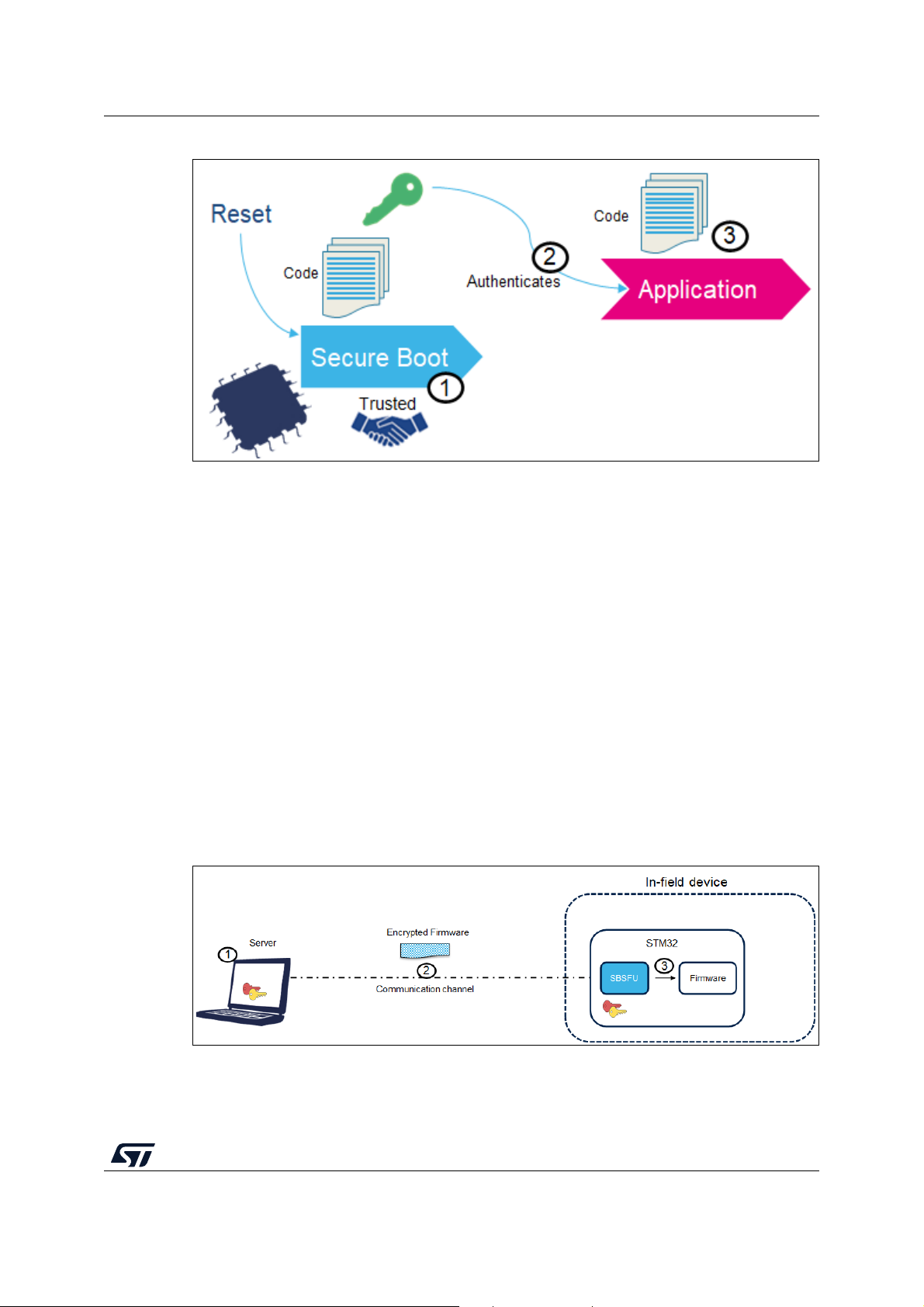
3.2 Secure Boot
Secure Boot (SB) asserts the integrity and authenticity of the user application image that is
executed: cryptographic checks are used to prevent any unauthorized or maliciously
modified software from running. The Secure Boot process implements a Root of Trust (refer
to Figure
authenticated (2) before its execution (3).
The integrity is verified to be sure that the image that is going to be executed has not been
corrupted or maliciously modified.
An authenticity check aims to verify that the firmware image is coming from a trusted and
known source to prevent unauthorized entities to install and execute code.
1): starting from this trusted component (1), every other component is
14/104 UM2262 Rev 8
Page 15
UM2262 Secure Boot and Secure Firmware Update (SBSFU)
Figure 1. Secure Boot Root of Trust
3.3 Secure Firmware Update
Secure Firmware Update (SFU) provides a secure implementation of in-field firmware
updates, enabling the download of new firmware images to a device in a secure way.
As shown in Figure 2, two entities are typically involved in a firmware update process:
• Server
– OEM manufacturer server/web service
– Stores the new version of device firmware
– Communicates with the device and sends the new image version in an encrypted
form if it is available
• Device
– Deployed in the field
– Embeds a code running firmware update process.
– Communicates with the server and receives a new firmware image.
– Authenticates decrypts and installs the new firmware image then executes it.
Figure 2. Typical in-field device update scenario
UM2262 Rev 8 15/104
102
Page 16

Secure Boot and Secure Firmware Update (SBSFU) UM2262
Firmware update runs through the following steps:
1. If a firmware update is needed, a new encrypted firmware image is created and stored
in the server.
2. The new encrypted firmware image is sent to the device deployed in the field through
an untrusted channel.
3. The new image is downloaded, checked, and installed.
The firmware update can be done on the complete firmware image, or only on a portion of
the firmware image (only for dual-slot configuration).
The firmware update is vulnerable to the threats presented in Section 3.1: Product security
introduction: cryptography is used to ensure confidentiality, integrity, and authentication.
The confidentiality is implemented to protect the firmware image, which may be a key
asset for the manufacturer. The firmware image sent over the untrusted channel is
encrypted so that only devices having access to the encryption key can decrypt the firmware
package.
The integrity is verified to be sure that the received image is not corrupted.
The authenticity check aims to verify that the firmware image is coming from a trusted and
known source, to prevent unauthorized entities to install and execute code.
3.4 Cryptography operations
The X-CUBE-SBSFU STM32Cube Expansion Package is delivered with four cryptographic
schemes using both asymmetric and symmetric cryptography.
The default cryptographic scheme demonstrates ECDSA asymmetric cryptography for
firmware verification and AES-CBC symmetric cryptography for firmware decryption.
Thanks to asymmetric cryptography, the firmware verification can be performed with publickey operations so that no secret information is required in the device.
The alternative cryptographic schemes provided in the X-CUBE-SBSFU Expansion
Package are:
• ECDSA asymmetric cryptography for firmware verification with AES-CBC or AES-CTR
symmetric cryptography for firmware encryption
• ECDSA asymmetric cryptography for firmware verification without firmware encryption
• X509 certificate-based ECDSA asymmetric cryptography for firmware verification
without firmware encryption
• AES-GCM symmetric cryptography for both firmware verification and encryption.
Tabl e 3 presents the various security features associated with each of the cryptographic
schemes.
16/104 UM2262 Rev 8
Page 17

UM2262 Secure Boot and Secure Firmware Update (SBSFU)
Features
Asymmetric
with AES encryption
Table 3. Cryptographic scheme comparison
Asymmetric
without encryption
X509 certificate-based
asymmetric without
encryption
Symmetric
(AES-GCM)
(1)
AES-CBC encryption,
or AES-CTR
Confidentiality
encryption for STM32
MCUs supporting
No, the user FW is in a clear format.
AES-GCM encryption
(FW binary)
OTFDEC processing
(FW binary)
Integrity SHA256 (FW header and FW binary)
Authentication
Cryptographic
keys in device
1. For the symmetric cryptographic scheme, it is highly recommended to configure a unique symmetric key for each product.
– SHA256 of the FW header is ECDSA signed
– SHA256 of the FW binary stored in FW header
Private AES-CBC /
AES-CTR key (secret)
Public ECDSA key
Public ECDSA key
Public ECDSA key in
X509 certificate chain
(stored in STSAFE-A or
KMS)
AES-GCM Tag
(FW header and FW
binary)
Private AES-GCM
key (secret)
UM2262 Rev 8 17/104
102
Page 18

Key management services UM2262
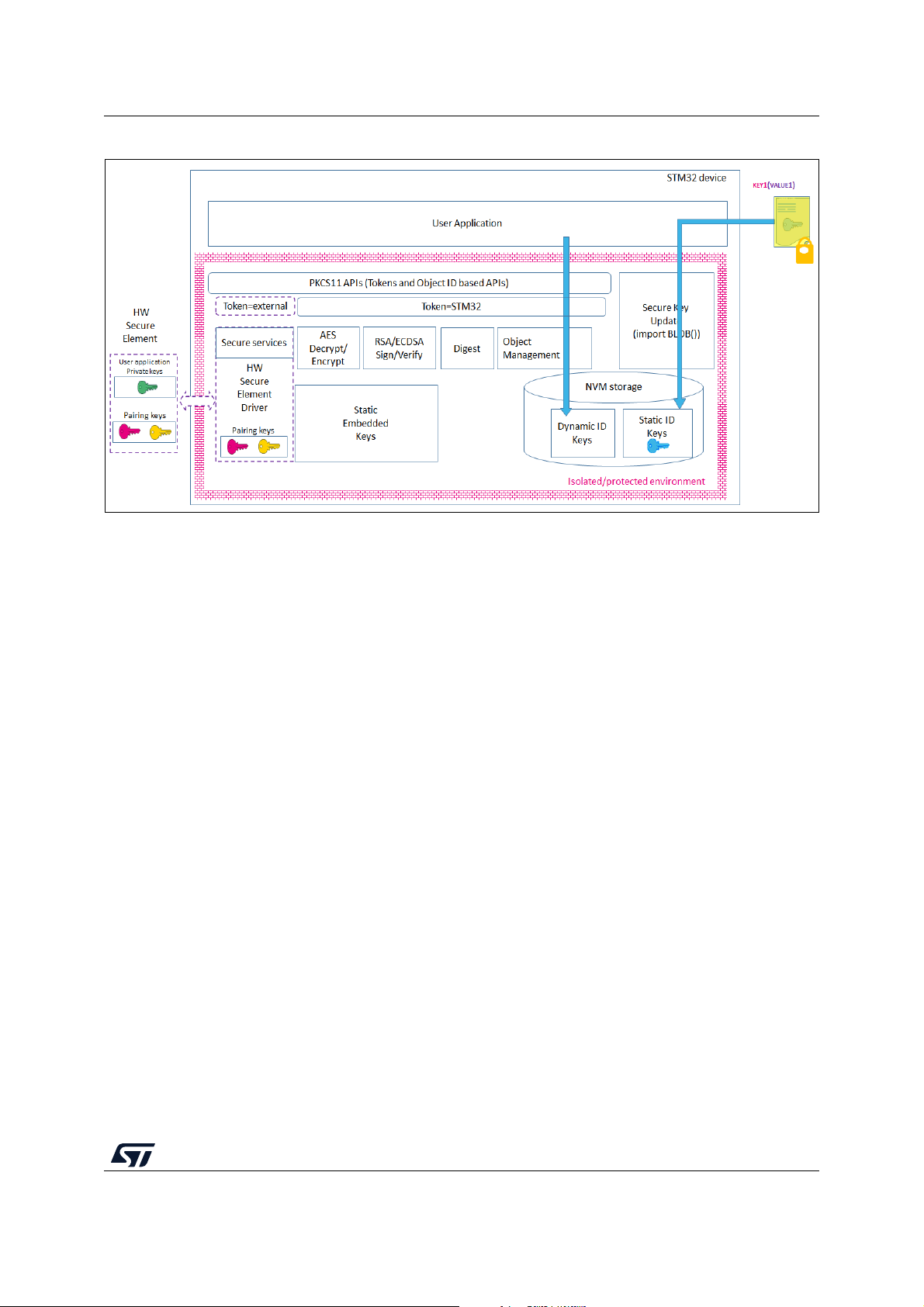
4 Key management services
Key management services (KMS) middleware provides cryptographic services through the
standard PKCS #11 APIs (specified by OASIS) allowing to abstract the key value to the
caller (using object ID and not directly the key-value). KMS is executed inside a
protected/isolated environment to ensure that key value cannot be accessed by an
unauthorized code running outside the protected/isolated environment.
KMS also offers the possibility to use cryptographic services with keys that are managed
securely outside the STM32 microcontroller, such as by an STSAFE-A110 Secure Element
for example (rooting based on token ID).
KMS only supports a subset of PKCS #11 APIs:
• Object management functions: creation / update / deletion
• AES encryption functions
• AES decryption functions
• Digesting functions
• RSA and ECDSA Signing/Verifying functions
• Key management functions: key generation/derivation
KMS manages three types of keys:
• Static Embedded keys:
– Predefined keys are embedded within the code. Such keys can't be modified.
• Updatable keys with Static ID:
– Keys IDs are predefined in the system
– The key value can be updated in an NVM storage via a secure procedure using
static embedded root keys (authenticity check, data integrity check, and data
decryption)
– Key cannot be deleted
• Updatable keys with dynamic ID:
– Key IDs are defined when creating the keys
– The key value is created using internal functions. Typically, the DeriveKey()
function creates dynamic objects.
– Key can be deleted
18/104 UM2262 Rev 8
Page 19
UM2262 Key management services
Figure 3. KMS functions overview
For more details regarding the OASIS PKCS #11 standard, refer to [5].
UM2262 Rev 8 19/104
102
Page 20
Protection measures and security strategy UM2262
5 Protection measures and security strategy
Cryptography ensures integrity, authentication, and confidentiality. However, the use of
cryptography alone is not enough: a set of measures and system-level strategies are
needed for protecting critical operations and sensitive data (such as a secret key), and the
execution flow, to resist possible attacks.
Secure software coding techniques such as doubling critical tests, doubling critical actions,
checking parameters values, and testing a flow control mechanism, are implemented to
resist basic fault-injection attacks.
The security strategy is based on the following concepts:
• Ensure single entry point at reset: force code execution to start with Secure Boot code
• Make SBSFU code and SBSFU secrets immutable: no possibility to modify or alter
them once security is fully activated
• Create a protected enclave isolated from SBSFU application and user applications to
store secrets such as keys, and to run critical operations such as cryptographic
algorithms
• Limit surface execution to SBSFU code during SBSFU application execution
• Remove JTAG access to the device
• Monitor the system: intrusion detection and SBSFU execution time
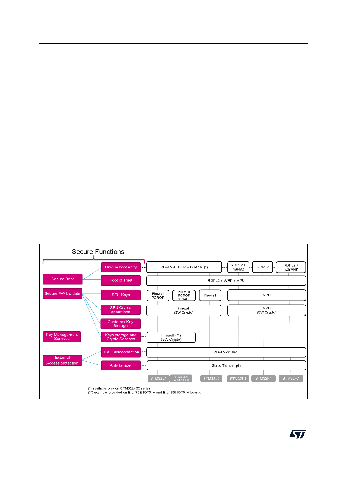
Figure 4 and Figure 5 give a high-level view of the security mechanisms activated on each
STM32 Series.
Figure 4. SBSFU security IPs vs. STM32 Series (1 of 2)
20/104 UM2262 Rev 8
Page 21
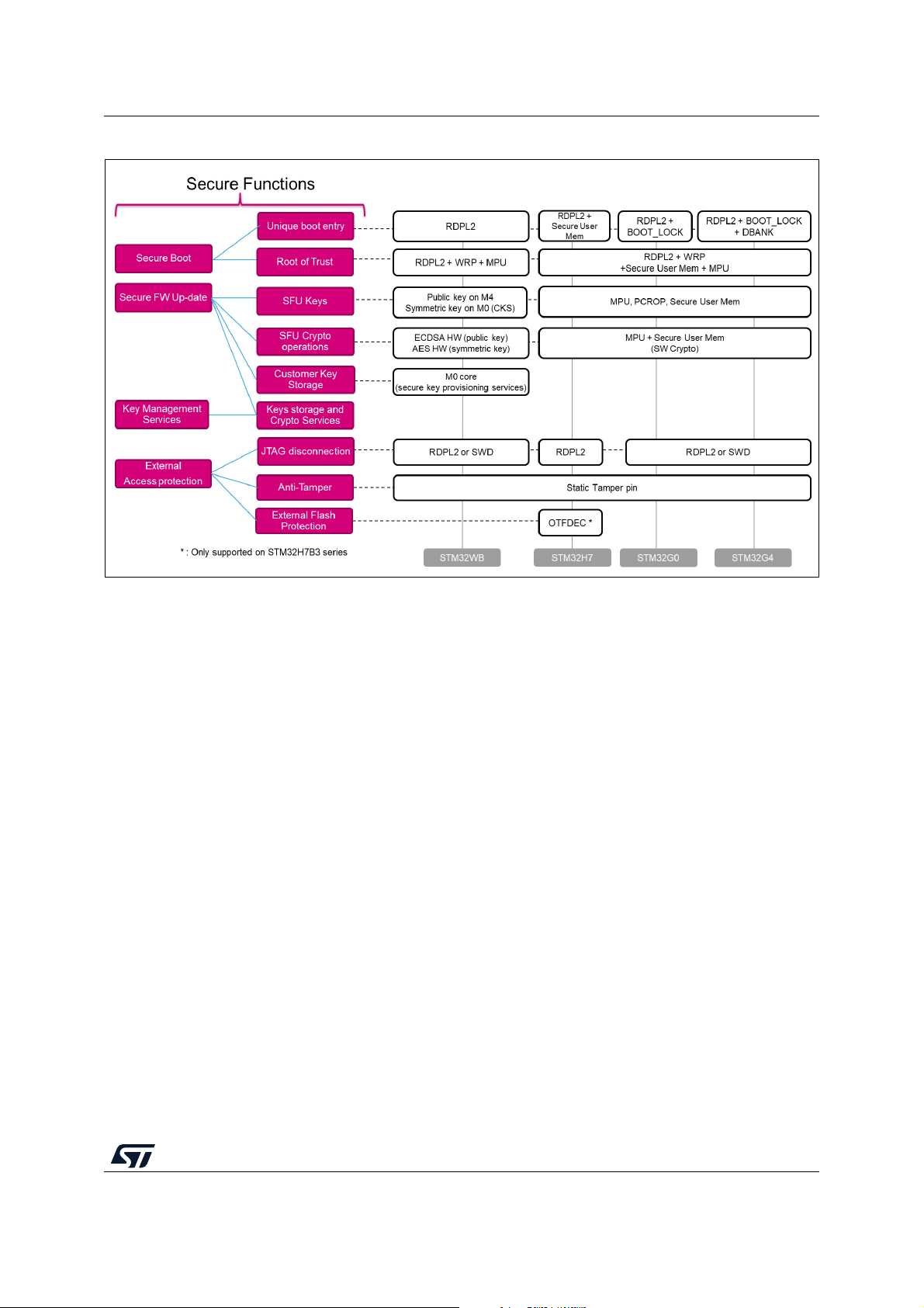
UM2262 Protection measures and security strategy
Figure 5. SBSFU security IPs vs. STM32 Series (2 of 2)
5.1 STM32L4 Series and STM32L0 Series
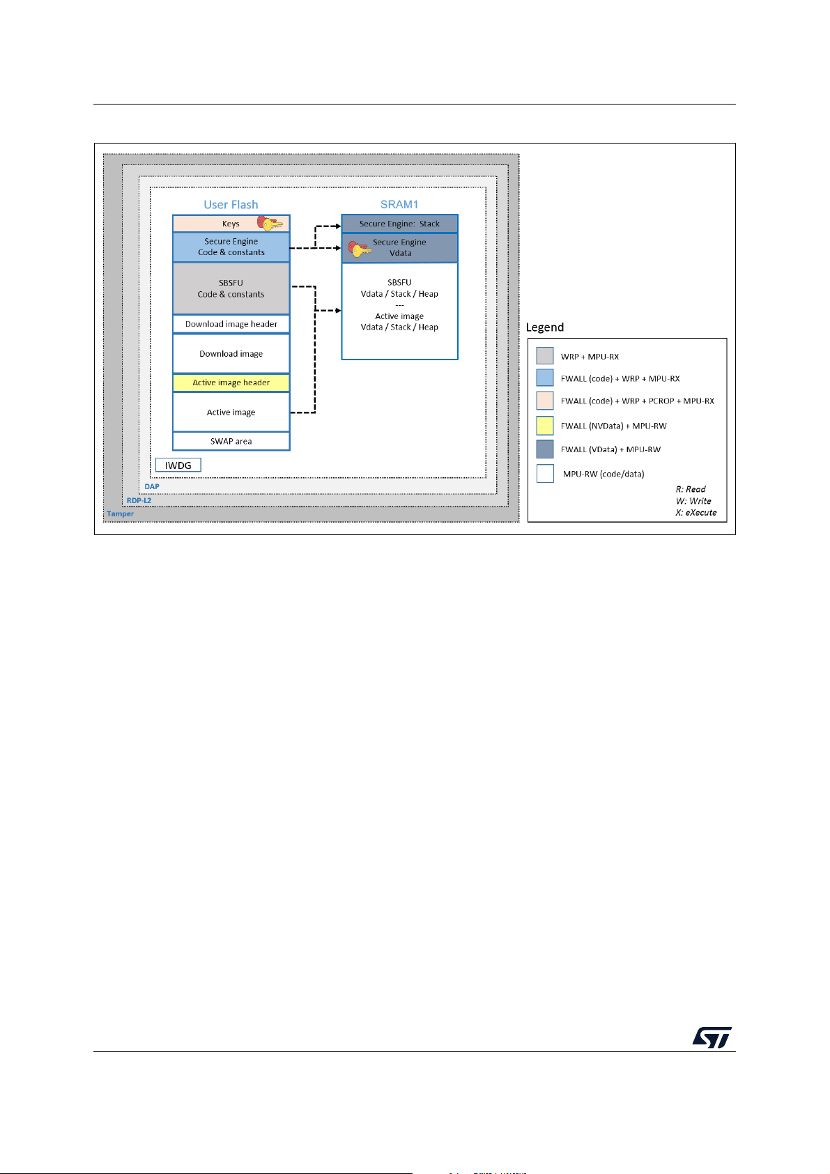
Figure 6 illustrates how the system, the code, and the data are protected in the
X-CUBE-SBSFU application example for the STM32L4 Series and STM32L0 Series.
UM2262 Rev 8 21/104
102
Page 22
Protection measures and security strategy UM2262
Figure 6. STM32L4 and STM32L0 protection overview during SBSFU execution
22/104 UM2262 Rev 8
Page 23

UM2262 Protection measures and security strategy
Protections against outer attacks
Outer attacks refer to attacks triggered by external tools such as debuggers or probes,
trying to access the device. In the SBSFU application example, RDP, tamper, DAP, and
IWDG protections are used to protect the product against outer attacks:
• RDP (Read Protection): Read Protection Level 2 is mandatory to achieve the highest
level of protection and to implement a Root of Trust:
– External access via the JTAG hardware interface to RAM and Flash is forbidden.
This prevents attacks aiming to change SBSFU code and therefore mining the
Root of Trust.
– Option bytes cannot be changed. This means that other protections such as WRP
and PCROP cannot be changed anymore.
Caution - RDP level 1 is not proposed for the following reasons:
1. Secure Boot / Root of Trust (single entry point and immutable code) cannot be
ensured, because Option bytes (WRP) can be modified in RDP L1.
2. Device internal flash can be fully reprogrammed (after flash mass erase via RDP L0
regression) with a new FW without any security.
3. Secrets in RAM protected by the firewall can be accessed by attaching the debugger
via the JTAG hardware interface on a system reset.
In case JTAG hardware interface access is not possible at customer product, and in
case the customer uses a trusted and reliable user application code, then the abovehighlighted risks are not valid.
• Tam p e r : the anti-tamper protection is used to detect physical tampering actions on the
device and to take related countermeasures. In the case of tampering detection, the
SBSFU application example forces a reboot.
• DAP (Debug Access Port): the DAP protection consists of de-activating the DAP
(Debug Access Port). Once de-activated, JTAG pins are no longer connected to the
STM32 internal bus. DAP is automatically disabled with RDP Level 2.
• IWDG (Independent Watchdog): IWDG is a free-running down-counter. Once running,
it cannot be stopped. It must be refreshed periodically before it causes a reset. This
mechanism allows the control of SBSFU execution duration.
Protections against inner attacks
Inner attacks refer to attacks triggered by code running in the STM32. Attacks may be due
to either malicious firmware exploiting bugs or security breaches, or unwanted operations.
In the SBSFU application example, WRP, firewall, PCROP, and MPU protections preserve
the product from inner attacks:
• FWALL (firewall): the firewall is configured to protect the code, volatile and non-volatile
data. Protected code is accessible through a single entry point (the call gate
mechanism is described in Appendix A). Any attempt to jump and try to execute any of
the functions included in the code section without passing through the entry point
generates a system reset.
In the KMS example, keys and cryptographic services are executed inside the isolated
environment under firewall protection.
UM2262 Rev 8 23/104
102
Page 24
Protection measures and security strategy UM2262
• PCROP
(1)
(proprietary code readout protection): a section of Flash memory is defined
as execute-only through PCROP protection. It is not possible to access this section in
reading nor writing. Being an execute-only area, a key is protected with PCROP only if
it is ‘embedded’ in a piece of code: executing this code moves the key to a specific
pointer in RAM. Placed behind the firewall, its execution is not possible from outside.
• WRP (write protection): write protection is used to protect trusted code from external
attacks or even internal modifications such as unwanted writings/erase operations on
critical code/data.
• MPU (memory protection unit): the MPU is used to make an embedded system more
robust by splitting the memory map for Flash and SRAMs into regions having their
access rights. In the SBSFU application example, MPU is configured to ensure that no
other code is executed from any memories during SBSFU code execution. When
leaving the SBSFU application, the MPU configuration is updated to authorize also the
execution of the user application code.
1. Read protection is tightly coupled with write protection for the STM32L0 Series: when activated, any readprotected sector is also write-protected. For this reason, read protection cannot be activated.
5.2 STM32F4 Series, STM32F7 Series, and STM32L1 Series
Figure 7 illustrates how the system, the code, and the data are protected in the
X-CUBE-SBSFU application example for the STM32F4 Series, STM32F7 Series, and
STM32L1 Series.
Figure 7. STM32F4, STM32F7 and STM32L1 protection overview during SBSFU execution
24/104 UM2262 Rev 8
Page 25

UM2262 Protection measures and security strategy
Protections against outer attacks
Outer attacks refer to attacks triggered by external tools such as debuggers or probes,
trying to access the device. In the SBSFU application example, RDP, tamper, DAP, and
IWDG protections are used to protect the product against outer attacks:
• RDP (Read Protection): Read Protection Level 2 is mandatory to achieve the highest
level of protection and to implement a Root of Trust:
– External access via the JTAG hardware interface to RAM and Flash is forbidden.
This prevents attacks aiming to change SBSFU code and therefore mining the
Root of Trust.
– Option bytes cannot be changed. This means that other protections such as WRP
and PCROP cannot be changed anymore.
Caution - RDP level 1 is not proposed for the following reasons:
1. Secure Boot / Root of Trust (single entry point and immutable code) cannot be
ensured, because Option bytes (WRP) can be modified in RDP L1.
2. Device internal flash can be fully reprogrammed (after flash mass erase via RDP L0
regression) with a new FW without any security.
3. Secrets in RAM protected by the firewall can be accessed by attaching the debugger
via the JTAG hardware interface on a system reset.
In case JTAG hardware interface access is not possible at customer product, and in
case the customer uses a trusted and reliable user application code, then the abovehighlighted risks are not valid.
• Tam p e r : the anti-tamper protection is used to detect physical tampering actions on the
device and to take related countermeasures. In the case of tampering detection, the
SBSFU application example forces a reboot.
• DAP (Debug Access Port): the DAP protection consists of de-activating the DAP
(Debug Access Port). Once de-activated, JTAG pins are no longer connected to the
STM32 internal bus. DAP is automatically disabled with RDP Level 2.
• IWDG (Independent Watchdog): IWDG is a free-running down-counter. Once running,
it cannot be stopped. It must be refreshed periodically before it causes a reset. This
mechanism allows the control of SBSFU execution duration.
Protections against inner attacks
Inner attacks refer to attacks triggered by code running in the STM32. Attacks may be due
to either malicious firmware exploiting bugs or security breaches, or unwanted operations.
In the SBSFU application example, WRP and MPU protections preserve the product from
inner attacks:
• WRP (write protection): write protection is used to protect trusted code from external
attacks or even internal modifications such as unwanted writing or erase operations on
critical code or data.
• MPU (memory protection unit): the protected environment managing all critical data
and operations (Secure Engine) is isolated from the other software components by
leveraging the MPU. The Secure Engine code and data can be accessed only through
a privileged level of software execution. Therefore, software running at a non-privileged
level cannot call the Secure Engine services nor access the critical data. This strict
access control to Secure Engine services and resources is implemented by defining
specific MPU regions as described in Table 4 .
UM2262 Rev 8 25/104
102
Page 26
Protection measures and security strategy UM2262
Table 4. MPU regions in the STM32F4 Series, STM32F7 Series, and STM32L1 Series
Region content Privileged permission Unprivileged permission
Secure Engine code & constants
Secure Engine stack & VDATA
Read Only
(execution allowed)
Read Write
(not executable)
No access
No access
Besides, the MPU also ensures that only authorized code is granted execution permission
when the Secure Boot and Secure Firmware Update processes are running. This is the
reason why the MPU configuration is updated before launching the user application to
authorize its execution. Nevertheless, the Secure Engine isolation settings and supervisor
call mechanisms still apply when running the user application (not only when running the
SBSFU code).
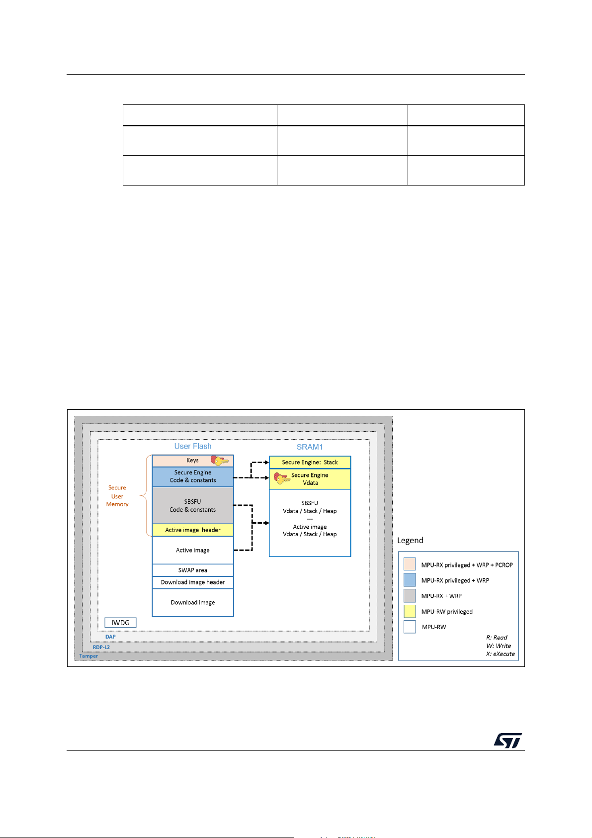
5.3 STM32G0 Series, STM32G4 Series, and STM32H7 Series
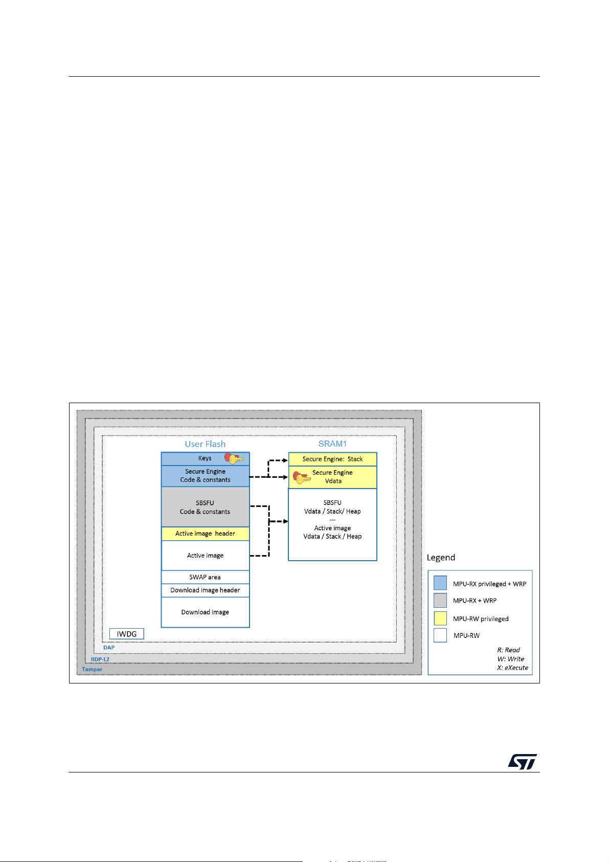
Figure 8 illustrates how the system, the code, and the data are protected in the
X-CUBE-SBSFU application example for the STM32G0 Series, STM32G4 Series, and
STM32H7 Series.
For the specificities of STM32H7B3 devices, refer to appendix I.2: External Flash on
STM32H7B3 devices.
Figure 8. STM32G0, STM32G4, and STM32H7 protection overview during SBSFU execution
26/104 UM2262 Rev 8
Page 27

UM2262 Protection measures and security strategy
Protections against outer attacks
Outer attacks refer to attacks triggered by external tools such as debuggers or probes,
trying to access the device. In the SBSFU application example, RDP, tamper, DAP, and
IWDG protections are used to protect the product against outer attacks:
RDP (Read Protection):
• Read Protection Level 2 allows achieving the highest level of protection and to
implement a Root of Trust.
– External access via the JTAG HW interface to RAM and Flash is forbidden. This
prevents attacks aiming to change SBSFU code and therefore mining the Root of
Trust.
– Option bytes cannot be changed. This means that other protections such as WRP
and PCROP cannot be changed anymore.
• Read Protection level 1 allows achieving a lower level of protection than RDP level 2
for the following reasons:
– Code / Data stored in internal Flash can be modified (removing immutability), once
Option bytes (WRP) is reset (not possible in RDP Level 2).
– Device internal flash can be fully reprogrammed in RDP level 1 (after Flash mass
erase via RDP L0 regression) with a new FW without any security.
– Secrets in RAM can be accessed by attaching the debugger via the JTAG HW
interface on a system reset
• Read Protection Level 0 does not support any protection and full product access is
allowed.
(1)
.
Secure Boot / Root of Trust: After reset, that part of the customer code is forced to run first
using the BOOT_Lock configuration. It is isolated from the rest of the runtime FW using the
Securable memory area protection.
Tamper: The anti-tamper protection is used to detect physical tampering actions on the
device and to take related countermeasures. In the case of tampering detection, the SBSFU
application example forces a reboot.
DAP (Debug Access Port): The DAP protection consists of de-activating the DAP (Debug
Access Port). Once de-activated, JTAG pins are no longer connected to the STM32 internal
bus. DAP is automatically disabled with RDP Level 2.
IWDG (Independent Watchdog): IWDG is a free-running down-counter. Once running, it
cannot be stopped. It must be refreshed periodically before it causes a reset. This
mechanism allows the control of SBSFU execution duration.
1. Not possible on the STM32H7 Series. Refer to Appendix If or more details.
UM2262 Rev 8 27/104
102
Page 28
Protection measures and security strategy UM2262
Protections against inner attacks: Inner attacks refer to attacks triggered by code
running in the STM32. Attacks may be due to either malicious firmware exploiting bugs or
security breaches, or unwanted operations.
In the SBSFU application example, PCROP, WRP, and MPU protections preserve the
product from inner attacks:
• PCROP (proprietary code readout protection): a section of Flash is defined as execute-
only through PCROP protection. It is not possible to access this section in reading nor
writing. Being an execute-only area, a key is protected with PCROP only if it is
‘embedded’ in a piece of code: executing this code moves the key to a specific pointer
in RAM. Placed behind the firewall, its execution is not possible from outside.
• WRP (write protection): write protection is used to protect trusted code from external
attacks or even internal modifications such as unwanted writings/erase operations on
critical code/data.
• MPU (memory protection unit): the protected environment managing all critical data
and operations (Secure Engine) is isolated from the other software components by
leveraging the Memory Protection Unit (MPU). The Secure Engine code and data can
be accessed only through a privileged level of software execution. Therefore, software
running at a non-privileged level cannot call the Secure Engine services nor access the
critical data. This strict access control to Secure Engine services and resources is
implemented by defining specific MPU regions described in Table 5.
Table 5. MPU regions in the STM32G0 Series, STM32G4 Series, and STM32H7 Series
Region content Privileged permission Unprivileged permission
Secure Engine code & constants
Secure Engine stack & VDATA
Read Only
(execution allowed)
Read Write
(not executable)
No access
No access
Besides, the MPU also ensures that only authorized code is granted execution
permission when the Secure Boot and Secure Firmware Update processes are
running.
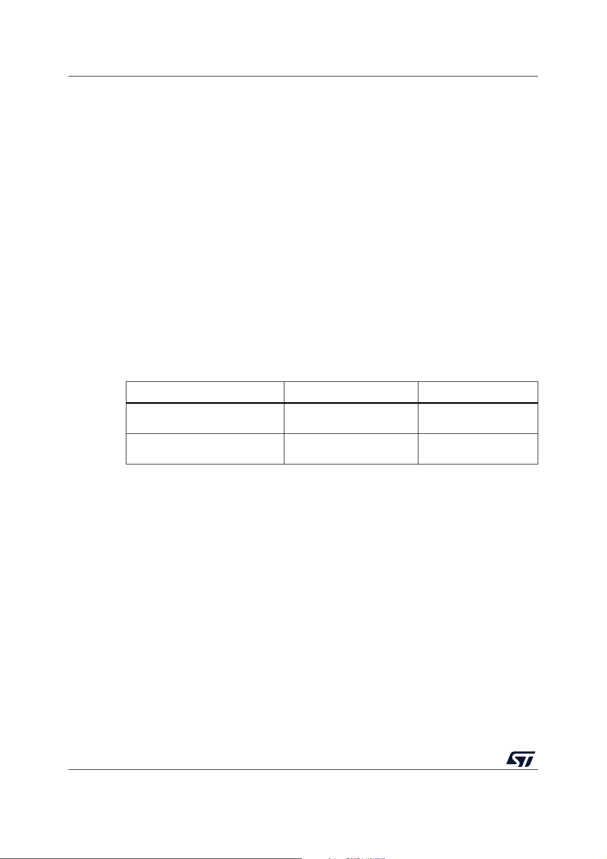
Before launching the user application, the MPU protection is disabled but the secure
user memory protection is activated.
• Secure user memory: when the secure user memory protection is activated, any
access to securable memory area (fetch, read, programming, erase) is rejected,
generating a bus error. All the code and secrets located inside the secure user memory
(a protected environment) is fully hidden. Secure Engine stack and data are cleared
when launching the user application as not under secure user memory protection.
Figure 9 illustrates the closure of secure user memory when starting the user application.
28/104 UM2262 Rev 8
Page 29
UM2262 Protection measures and security strategy
Figure 9. STM32G0, STM32G4, and STM32H7 protection overview
during user application execution
UM2262 Rev 8 29/104
102
Page 30
Protection measures and security strategy UM2262
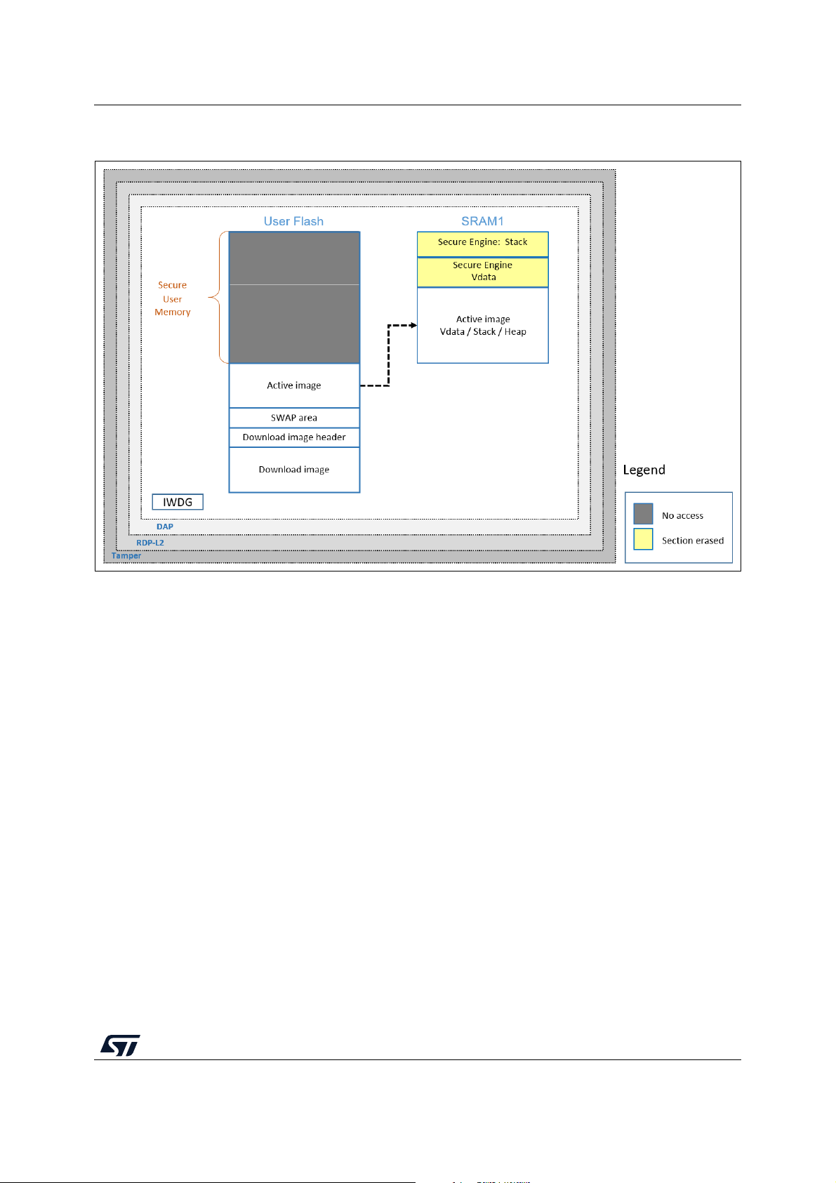
5.4 STM32WB Series
Figure 10 illustrates how the system, the code, and the data are protected in the
X-CUBE-SBSFU application example for the STM32WB Series.
Figure 10. STM32WB protection overview during SBSFU execution
30/104 UM2262 Rev 8
Page 31

UM2262 Protection measures and security strategy
Protections against outer attacks
Outer attacks refer to attacks triggered by external tools such as debuggers or probes,
trying to access the device. In the SBSFU application example, RDP, tamper, DAP, and
IWDG protections are used to protect the product against outer attacks:
• RDP (Read Protection): Read Protection Level 2 is mandatory to achieve the highest
level of protection and to implement a Root of Trust:
– External access via the JTAG hardware interface to RAM and Flash is forbidden.
This prevents attacks aiming to change SBSFU code and therefore mining the
Root of Trust.
– Option bytes cannot be changed. This means that other protections such as WRP
and PCROP cannot be changed anymore.
Caution - RDP level 1 is not proposed for the following reasons:
1. Secure Boot / Root of Trust (single entry point and immutable code) cannot be
ensured, because Option bytes (WRP) can be modified in RDP L1.
2. Device internal flash can be fully reprogrammed (after flash mass erase via RDP L0
regression) with a new FW without any security.
3. Secrets in RAM protected by the firewall can be accessed by attaching the debugger
via the JTAG hardware interface on a system reset.
In case JTAG hardware interface access is not possible at customer product, and in
case the customer uses a trusted and reliable user application code, then the abovehighlighted risks are not valid.
• Tam p e r : the anti-tamper protection is used to detect physical tampering actions on the
device and to take related countermeasures. In the case of tampering detection, the
SBSFU application example forces a reboot.
• DAP (Debug Access Port): the DAP protection consists of de-activating the DAP
(Debug Access Port). Once de-activated, JTAG pins are no longer connected to the
STM32 internal bus. DAP is automatically disabled with RDP Level 2.
• IWDG (Independent Watchdog): IWDG is a free-running down-counter. Once running,
it cannot be stopped. It must be refreshed periodically before it causes a reset. This
mechanism allows the control of SBSFU execution duration.
Protections against inner attacks
Inner attacks refer to attacks triggered by code running in the STM32. Attacks may be due
to either malicious firmware exploiting bugs or security breaches, or unwanted operations.
In the SBSFU application example, CKS, WRP, and MPU protections preserve the product
from inner attacks:
• CKS (customer key storage): the SBSFU symmetric key is isolated in the Cortex®-M0+
core secure Flash and therefore cannot be accessed from the Cortex
each AES cryptographic decryption/encryption, the Cortex
®
Cortex
accessible from the Cortex
-M0+ code to load the key into the AES hardware accelerator key register (only
®
-M0+ core).
®
-M4 core requests the
• WRP (write protection): write protection is used to protect trusted code from external
attacks or even internal modifications such as unwanted writings/erase operations on
critical code/data. Moreover, WRP allows protecting the SBSFU public key.
• MPU (memory protection unit): the MPU is used to make an embedded system more
robust by splitting the memory map for Flash and SRAMs into regions having their
access rights. In the SBSFU application example, the MPU is configured to ensure that
no other code is executed from any memory during SBSFU code execution. When
UM2262 Rev 8 31/104
®
-M4 core. Before
102
Page 32

Protection measures and security strategy UM2262
leaving the SBSFU application, the MPU configuration is updated to authorize also the
execution of the user application code.
5.5 STM32L4 Series combined with STSAFE-A110
Figure 10 illustrates how the system, the code, and the data are protected in the
X-CUBE-SBSFU application example featuring the STM32L4 Series combined with
STSAFE-A110.
Figure 11. STM32L4 / STSAFE-A110 protection overview during SBSFU execution
32/104 UM2262 Rev 8
Page 33

UM2262 Protection measures and security strategy
STM32 microcontroller protections against outer attacks
Outer attacks refer to attacks triggered by external tools such as debuggers or probes,
trying to access the device. In the SBSFU application example, RDP, tamper, DAP, and
IWDG protections are used to protect the product against outer attacks:
• RDP (Read Protection): Read Protection Level 2 is mandatory to achieve the highest
level of protection and to implement a Root of Trust:
– External access via the JTAG hardware interface to RAM and Flash is forbidden.
This prevents attacks aiming to change SBSFU code and therefore mining the
Root of Trust.
– Option bytes cannot be changed. This means that other protections such as WRP
and PCROP cannot be changed anymore.
Caution - RDP level 1 is not proposed for the following reasons:
1. Secure Boot / Root of Trust (single entry point and immutable code) cannot be
ensured, because Option bytes (WRP) can be modified in RDP L1.
2. Device internal flash can be fully reprogrammed (after flash mass erase via RDP L0
regression) with a new FW without any security.
3. Secrets in RAM protected by the firewall can be accessed by attaching the debugger
via the JTAG hardware interface on a system reset.
In case JTAG hardware interface access is not possible at customer product, and in
case the customer uses a trusted and reliable user application code, then the abovehighlighted risks are not valid.
• Tam p e r : the anti-tamper protection is used to detect physical tampering actions on the
device and to take related countermeasures. In the case of tampering detection, the
SBSFU application example forces a reboot.
• DAP (Debug Access Port): the DAP protection consists of de-activating the DAP
(Debug Access Port). Once de-activated, JTAG pins are no longer connected to the
STM32 internal bus. DAP is automatically disabled with RDP Level 2.
• IWDG (Independent Watchdog): IWDG is a free-running down-counter. Once running,
it cannot be stopped. It must be refreshed periodically before it causes a reset. This
mechanism allows the control of SBSFU execution duration.
STM32 microcontroller protections against inner attacks
Inner attacks refer to attacks triggered by code running in the STM32. Attacks may be due
to either malicious firmware exploiting bugs or security breaches, or unwanted operations.
In the SBSFU application example, WRP, firewall, PCROP, and MPU protections preserve
the product from inner attacks:
• FWALL (firewall): the firewall is configured to protect the code, volatile and non-volatile
data. Protected code is accessible through a single entry point (the call gate
mechanism is described in Appendix A). Any attempt to jump and try to execute any of
the functions included in the code section without passing through the entry point
generates a system reset.
UM2262 Rev 8 33/104
102
Page 34

Protection measures and security strategy UM2262
• PCROP (proprietary code readout protection): a section of Flash is defined as execute-
only through PCROP protection. It is not possible to access this section in reading nor
writing. Being an execute-only area, a key is protected with PCROP only if it is
‘embedded’ in a piece of code: executing this code moves the key to a specific pointer
in RAM. Placed behind the firewall, its execution is not possible from outside.
• WRP (write protection): write protection is used to protect trusted code from external
attacks or even internal modifications such as unwanted writings/erase operations on
critical code/data.
• MPU (memory protection unit): the MPU is used to make an embedded system more
robust by splitting the memory map for Flash and SRAMs into regions having their
access rights. In the SBSFU application example, MPU is configured to ensure that no
other code is executed from any memories during SBSFU code execution. When
leaving the SBSFU application, the MPU configuration is updated to authorize also the
execution of the user application code.
STSAFE-A Secure Element protections
The STSAFE-A110 is a highly secure solution with a secure operating system running on
the latest generation of secure microcontrollers:
• Security features: The chip is CC EAL5+ AVA_VAN5 Common Criteria certified and
provides the following protections.
– Active shield
– Monitoring of environmental parameters
– Protection mechanism against faults
– Unique serial number on each die
– Protection against side-channel attacks
• Secure operating system: STSAFE-A110 runs a secure operating system offering
protection against logical and physical attacks.
• Secure channel and device binding: STSAFE-A110 allows a secure channel to be
set up with the STM32 to prevent eavesdropping of sensitive information on the I²C line
and to ensure pairing of a specific STM32 with a specific STSAFE-A110 (to prevent
cloning).
The secure channel is based on symmetric cryptography: two AES 128-bit keys (the socalled host pairing keys) are used to implement services such as command authorization,
command data encryption, response data encryption, and response authentication.
34/104 UM2262 Rev 8
Page 35

UM2262 Package description
6 Package description
This section details the X-CUBE-SBSFU package content and the way to use it.
6.1 General description
X-CUBE-SBSFU is a software package for STM32 microcontrollers.
It provides a complete solution to build Secure Boot and Secure Firmware Update
applications:
• Support of symmetric and asymmetric cryptography approaches with the AES-GCM,
AES-CBC, and ECDSA algorithms for decryption, verification, or both with the use of
X-CUBE-CRYPTOLIB
• Support of X509 certificate chain verification of firmware image and firmware
updates
• Two modes of operation:
– The dual-slot configuration with one active slot and one download slot, which
– The single-slot configuration with one active slot, which maximizes the user
• Integration of security peripherals and mechanisms to implement an SBSFU The Root
of Trust: RDP, WRP, PCROP, firewall, MPU, secure user memory, tamper, and IWDG
are combined to achieve the highest security level
• Use of a Secure Engine (SE) module as part of the middleware to provide a protected
environment managing all critical data and operations such as secure key storage,
cryptographic operations, and others
• Integration of secure key management services (KMS) offering symmetric and
asymmetric cryptographic services via the PKCS #11 APIs and offering secure key
storage, update services
• Integration of the STSAFE-A110 secure element to provide the system with a tamperresistant Root of Trust (CC EAL5+ AVA_VAN5 Common Criteria certified), to offload
(a)
enables safe image programming, with resume capability in the case of an
interruption of the installation procedure
application size
(b)
a. Specific to the STSAFE-A110.
b. The availability of security IPs depends on the STM32 Series.
UM2262 Rev 8 35/104
102
Page 36

Package description UM2262
the host MCU of ECDSA cryptographic operations. More information about STSAFEA110 can be found at www.st.com/stsafe-a110.
• Availability of the user application example source code.
• The firmware image configuration can be extended up to three images for a complex
system with multiple firmware (such as protocol stack, middleware, and user
application.)
• User application can validate the installation of the new active image(s) in case of
successful validation of new image through “self-test”.
• Management of interruption during code execution inside the firewall is now supported
for applications requiring low latency on interruption handling.
• Availability of the firmware image preparation tool provided both as executable and
source code.
X-CUBE-SBSFU is ported on the STM32F4 Series, STM32F7 Series, STM32G0 Series,
STM32G4 Series, STM32H7 Series, STM32L0 Series, STM32L1 Series, STM32L4 Series,
and STM32WB Series. X-CUBE-SBSFU is also ported on the STM32L4 Series combined
with STSAFE-A110 mounted on the B-L4S5I-IOT01A board.
The package includes sample applications that the developer can use to start experimenting
with the code.
The package is provided as a zip archive containing the source code.
The following integrated development environments are supported:
• STM32CubeIDE and System Workbench for STM32 (SW4STM32)
• IAR Embedded Workbench
• Keil
®
Microcontroller Development Kit (MDK-ARM)
®
for Arm® (EWARM)
Note: The KMS feature is available on the STM32L4 Series with an example provided on the B-
L475E-IOT01A and B-L4S5I-IOT01A boards.
The STSAFE-A110 feature is available on the STM32L4 Series with an example provided
on the B-L4S5I-IOT01A board.
36/104 UM2262 Rev 8
Page 37

UM2262 Package description
MSv46855V6
Application level
Middleware level
Drivers
User
application
SBSFU sample application
Hardware abstraction layer
(HAL)
Board support package
(BSP)
Utilities
CMSIS
PC
software
Secure
Engine
Cryptography
Secure Boot
Root of Trust
Secure
firmware
loader
Firmware
image
programming
Key
management
services
STSAFE-A
6.2 Architecture
This section describes the software components of the X-CUBE-SBSFU package illustrated
in Figure
12.
Figure 12. Software architecture overview
6.2.1 STM32CubeHAL
6.2.2 Board support package (BSP)
The HAL driver layer provides a generic multi-instance simple set of APIs (application
programming interfaces) to interact with the upper layers (application, libraries and
stacks). It is composed of generic and extension APIs. It is directly built around a
generic architecture and allows the layers that are built upon, such as the middleware
layer, implementing their functionalities without dependencies on the specific hardware
configuration for a given microcontroller unit (MCU).
This structure improves the library code re-usability and guarantees an easy portability
onto other devices.
The software package needs to support the peripherals on the STM32 boards apart
from the MCU. This software is included in the board support package (BSP). This is a
limited set of APIs which provides a programming interface for certain board-specific
peripherals such as the LED and the User button.
UM2262 Rev 8 37/104
102
Page 38

Package description UM2262
6.2.3 Cryptographic Library
Three different cryptographic middleware are supported:
• X-CUBE-CRYPTOLIB supports symmetric and asymmetric key approaches (AESGCM, AES-CBC, ECDSA) as well as hash computation (SHA256) for decryption and
verification. Software cryptographic functions are used to avoid storing secret keys in
hardware Crypto IP registers that are not protected.
• mbedTLS: cryptographic services delivered as open-source code. Similarly as for
X-CUBE-CRYPTOLIB, the symmetric and asymmetric key approaches (AES-GCM,
AES-CBC, ECDSA), as well as hash computation (SHA256) for decryption and
verification are supported. Examples are provided for the 32L496GDISCOVERY,
B-L475E-IOT01A, STM32F413H-Discovery, STM32F769I-Discovery,
P-NUCLEO-WB55.Nucleo, and NUCLEO-H753ZI boards under the folder
2_images_OSC.
• mbed-crypto: cryptographic services delivered as open-source code. This middleware
provides a PSA cryptography API implementation. Examples are provided for B-L4S5IIOT01A board, under the folders 2_Images_KMS and 2_Images_STSAFE.
6.2.4 Secure Engine (SE) middleware
The Secure Engine middleware provides a protected environment to manage all critical data
and operations (such as cryptography operations accessing firmware encryption key and
others). Protected code and data are accessible through a single entry point (call gate
mechanism) and it is therefore not possible to run or access any SE code or data without
passing through it, otherwise, a system reset is generated (refer to Appendix A to get details
about call gate mechanism).
Note: Secure Engine critical operations can be extended with other functions depending on user
application needs. Only trusted code is to be added to the Secure Engine environment
because it has access to the secrets.
6.2.5 Key management services (KMS) middleware
The secure key management services provide cryptographic services to the user
application through the PKCS #11 APIs (KEY ID-based APIs) that are executed inside the
secure enclave. User application keys are stored in the secure enclave and can be updated
securely (authenticity check, decryption, and integrity check before the update).
6.2.6 STSAFE-A middleware
STSAFE-A middleware provides a complete set of APIs to access all the STSAFE-A110
device features from STM32 microcontrollers.
It integrates both low-level communication drivers to interface with the STSAFE-A110
hardware, and higher-level processing exporting a set of command APIs to easily access
the device features from the STM32 microcontroller.
38/104 UM2262 Rev 8
Page 39

UM2262 Package description
6.2.7 Secure Boot and Secure Firmware Upgrade (SBSFU) application
Secure Boot (Root of Trust)
• Checks and applies the security mechanisms of the STM32 platform to protect critical
operations and secrets from attacks
• Authenticates and verifies the user application before each execution
Local download via UART Virtual COM
• Detects firmware download requests
• Downloads in STM32 Flash memory the new encrypted firmware image (header +
encrypted firmware) via the UART Virtual COM using Ymodem protocol and the Tera
Term tool (see Note)
FW installation management
• Detects new FW version to install
– From local download service via the UART interface
– Downloaded via the user application (dual-slot variant only)
• Secures FW upgrade:
– Authentication and integrity check
– FW decryption
– FW installation
– Anti-rollback mechanisms to avoid re-installation of previous firmware version
• Supports multiple images:
– Up to three active slots and three download slots for a complex system with
multiple firmware, such as protocol stack, middleware, and user application
– Specific cryptographic keys per slot
– Simultaneous image installation to ensure compatibility between firmware
• Supports single-slot configuration for maximizing the user application size
• Supports dual-slot configuration for safe image programming
– Installation process with firmware image validation. A rollback on the previous
firmware image is triggered at the next reset if the new firmware image is not
validated by the user application. The option is available under compilation switch
ENABLE_IMAGE_STATE_HANDLING. Refer to Appendix J to get details about
firmware image validation.
– Resume firmware installation: in the case of power off during the installation
process, installation is resumed at the next power on.
– Installation with the SWAP area to limit needed memory overhead. The rollback
option is then possible. (Refer to Appendix B to get details about multiple slots
management).
– Installation without the SWAP area to keep the download area encrypted. This is
required when the download slot is located in external Flash memory without
OTFDEC IP as for 2_Images_ExtFlash of B-L475E-IOT01A board.
– Partial update: flexibility to update the complete firmware image or a portion of it.
UM2262 Rev 8 39/104
102
Page 40

Package description UM2262
Note For applications delivered for the P-NUCLEO-WB55 Nucleo board, and 2_Images_ExtFlash
application on the STM32H7B3I-DK board, an example of a standalone loader is provided.
Refer to Appendix H for details.
6.2.8 User application
• Provides an example for downloading the user application via Ymodem protocol over a
UART (Over The Air download mechanisms, such as BLE, Wi-Fi
®
or others, can be
implemented in the user application but are not provided as examples in the
X-CUBE-SBSFU application example).
• Provides examples testing the protection mechanisms.
• Provides an example for using some of the functionalities exported by SE such as
getting information about the current firmware image.
• Provides examples using KMS exported services through a standard PKCS #11
interface: AES-GCM/CBC encryption/decryption, RSA signature/verification, key
provisioning, AES ECB key derivation, ECDSA key pair generation, and ECDH DiffieHellman key derivation.
• Provides examples to demonstrate STSAFE-A exported services through a standard
PKCS #11 interface: ECDSA signature generation using a device-unique private key,
device certificate reading, signature verification, ECDSA key pair generation, ECDH
Diffie-Hellman key derivation. These services are typically used in the context of a TLS
exchange and are candidate building blocks for the development of an IoT node
connected with a cloud-based service.
40/104 UM2262 Rev 8
Page 41

UM2262 Package description
6.3 Folder structure
A top-level view of the folder structure is shown in Figure 13 and Figure 14.
Figure 13. Project folder structure (1 of 2)
UM2262 Rev 8 41/104
102
Page 42
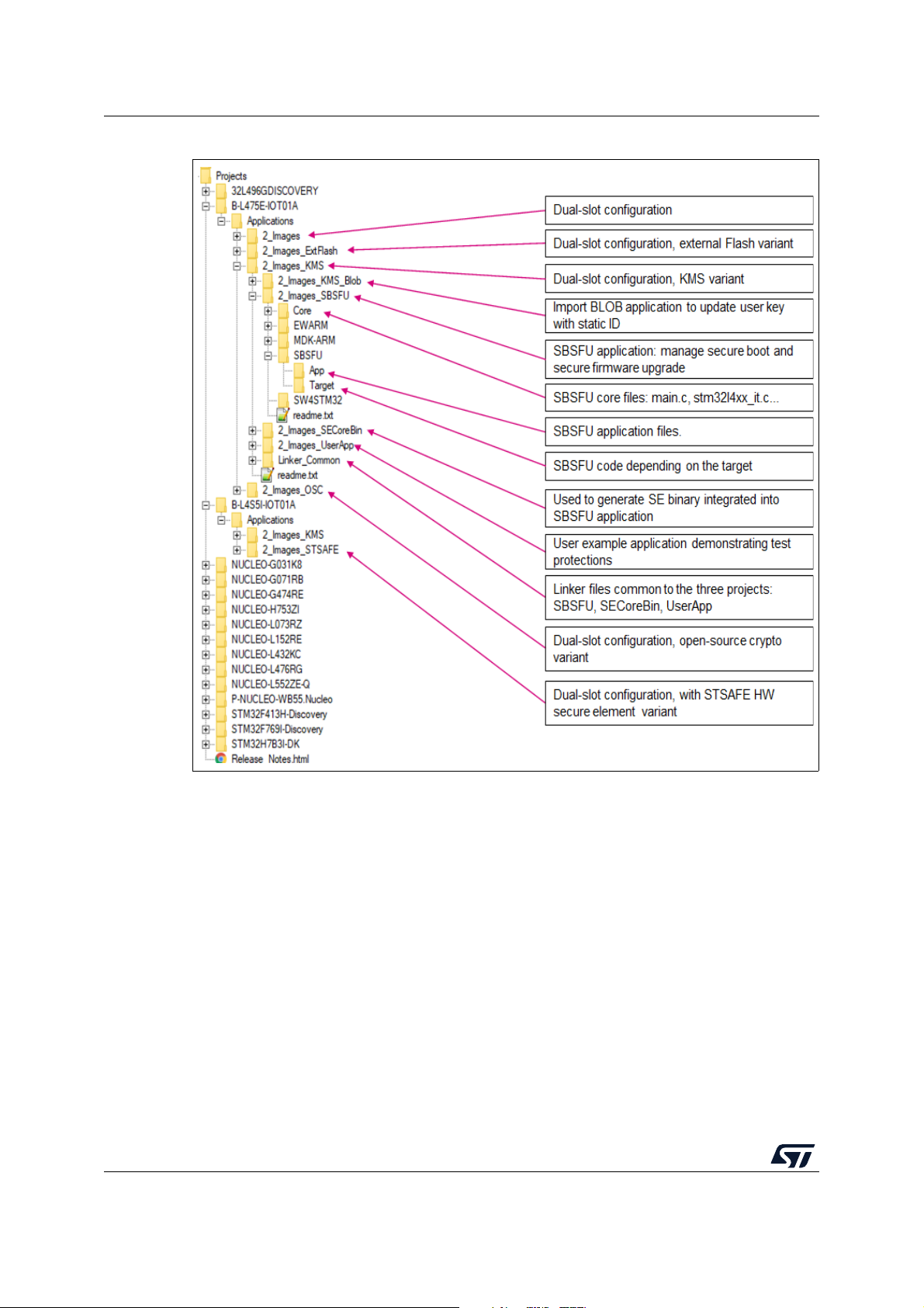
Package description UM2262
Figure 14. Project folder structure (2 of 2)
Note: Single-slot configuration is demonstrated in the application named 1_Image.
Dual slots configuration is demonstrated in examples named 2_Images.
6.4 APIs
Detailed technical information about the APIs is provided in a compiled HTML file located in
the STM32_Secure_Engine, STM32_Key_Management_Services, and STSAFE_A1xx
folders of the software package where all the functions and parameters are described.
42/104 UM2262 Rev 8
Page 43

UM2262 Package description
6.5 Application compilation process with IAR™ toolchain
Figure 15 outlines the steps needed to build the application and to demonstrate Secure
Boot and Secure Firmware Update:
• Step 1: Core binaries preparation
This step is needed to create the Secure Engine core binary including all the ‘trusted’
code and keys mapped in the firewall code section. The SE Callgate function is
specified as the entry point for the binary. The binary is linked with the SBSFU code in
step 2.
• Step 2: SBSFU
This step compiles the SBSFU source code implementing the state machine and
configuring the protections. It also links the code with the SECore binary generated at
step 1 to generate a single SBSFU binary including the SE trusted code. It also
generates a file including symbols for the user application to call the SE interface
methods, a set of user-friendly APIs wrapping the single SE call gate API.
• Step 3: user application example
It generates:
– The user application binary file that is uploaded to the device using the Secure
Firmware Update process (UserApp.sfb).
– A binary file concatenating the SBSFU binary, the user application binary in clear
format, and the corresponding FW header.
These three elements are placed properly for both the SBSFU and user
application to run when the binary file is flashed into the device with a flasher tool.
Hence, no FW installation procedure is required for SBSFU to start and boot the
user application. This is a convenient way to test the user application with a single
flashing stage.
Note: Refer to Appendix H for specificities of the STM32WB Series.
UM2262 Rev 8 43/104
102
Page 44

Package description UM2262
Figure 15. Application compilation steps
44/104 UM2262 Rev 8
Page 45

UM2262 Hardware and software environment setup
7 Hardware and software environment setup
This section describes the hardware and software setup procedures.
7.1 Hardware setup
To set up the hardware environment, one of the supported boards introduced in Section 6.1:
General description on page
cable. This connection with the PC allows the user:
• Flashing the board
• Interacting with the board via a UART console
• Debugging when the protections are disabled
7.2 Software setup
This section lists the minimum requirements for the developer to set up the SDK, run the
sample scenario, and customize applications.
36 must be connected to a personal computer via a USB
7.2.1 Development toolchains and compilers
Select one of the Integrated Development Environments supported by the STM32Cube
Expansion Package.
Take into account the system requirements and setup information provided by the selected
IDE provider.
7.2.2 Software tools for programming STM32 microcontrollers
ST-LINK utility
STM32 ST-LINK Utility (STSW-LINK004) is a full-featured software interface for
programming STM32 microcontrollers. It provides an easy-to-use and efficient environment
for reading, writing, and verifying a memory device.
Refer to the STSW-LINK004 STM32 ST-LINK Utility software on www.st.com.
Caution: Make sure to use an up-to-date version of ST-LINK.
STM32CubeProgrammer
STM32CubeProgrammer (STM32CubeProg) is an all-in-one multi-OS software tool for
programming STM32 microcontrollers. It provides an easy-to-use and efficient environment
for reading, writing, and verifying device memory through both the debug interface (JTAG
and SWD) and the bootloader interface (UART and USB).
STM32CubeProgrammer offers a wide range of features to program STM32 microcontroller
internal memories (such as Flash, RAM, and OTP) as well as external memories.
STM32CubeProgrammer also allows option programming and upload, programming
content verification, and microcontroller programming automation through scripting.
STM32CubeProgrammer is delivered in GUI (graphical user interface) and CLI (commandline interface) versions.
UM2262 Rev 8 45/104
102
Page 46
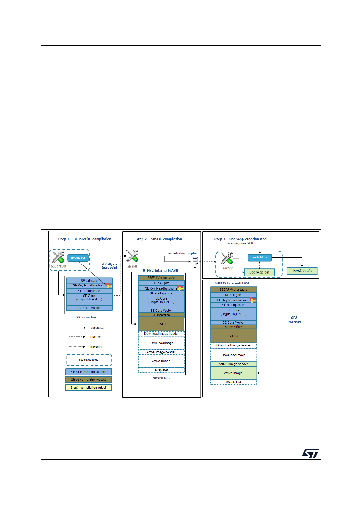
Hardware and software environment setup UM2262
Refer to the STM32CubeProgrammer software (STM32CubeProg) on www.st.com.
7.2.3 Terminal emulator
A terminal emulator software is needed to run the demonstration.
The example in this document is based on Tera Term, an open-source free software
terminal emulator that can be downloaded from the https://osdn.net/projects/ttssh2/ web
page. Any other similar tool can be used instead (Ymodem protocol support is required).
7.2.4 X-CUBE-SBSFU firmware image preparation tool
The X-CUBE-SBSFU Expansion Package for STM32Cube is delivered with the
prepareimage tool handling the cryptographic keys and firmware image preparation.
The prepareimage tool is delivered in two formats:
• Windows® executable: the standard Windows® command interpreter is required
• Python™ scripts: a Python™ interpreter as well as the elements listed in
Middlewares\ST\STM32_Secure_Engine\Utilities\KeysAndImages\readme.txt are
required
The Windows® executable is fully integrated into the supported IDEs and compilation
process as shown in Figure
16.
Figure 16. Firmware image preparation tool IDE integration
More information about the preparation tool is provided in Appendix E: Firmware image
preparation tool on page
46/104 UM2262 Rev 8
83.
Page 47
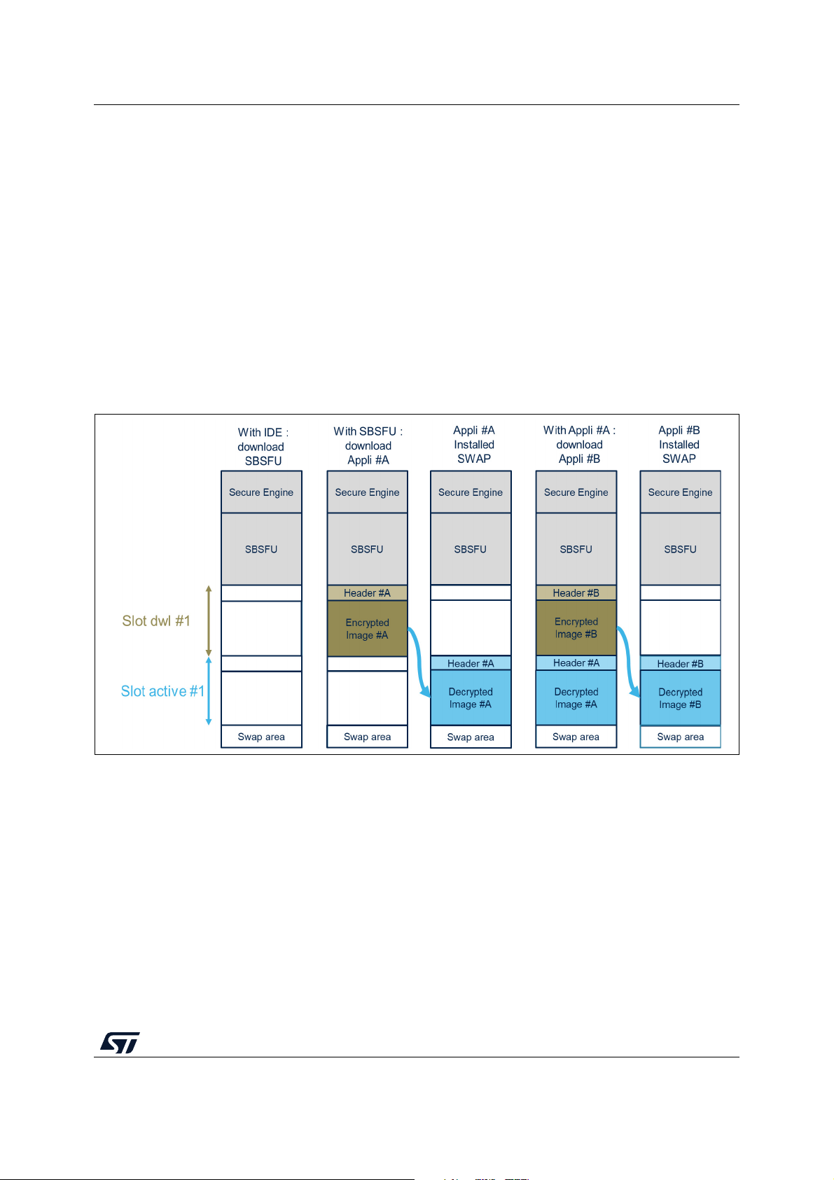
UM2262 Step-by-step execution
8 Step-by-step execution
The following steps describe a dual-slot SBSFU scenario executed on the NUCLEOL476RG board with the default cryptographic scheme, further illustrated in Figure
1. Download SBSFU application
2. SBSFU is running: download UserApp #A
3. UserApp #A is installed
4. UserApp #A is running, download UserApp #B
5. UserApp #B is installed then running
The UserApp#A and UserApp#B binaries are generated based on the user application
example project. Defining the application as #A or #B is done by changing the value of the
UserAppId variable declared in the main.c of the application.
Figure 17. Step-by-step execution
17:
UM2262 Rev 8 47/104
102
Page 48

Step-by-step execution UM2262
8.1 STM32 board preparation
The target Option bytes setting is the following for the NUCLEO-L476RG board:
• RDP Level 0 is set
• Write protection is disabled on all Flash pages
• PCROP protection is disabled
• BFB2 bit disabled
• Chip is erased
(b)
Option bytes setting can differ from one STM32 Series to another as illustrated in Figure 18.
Figure 18. STM32 board preparation
(a)
a. Automatically done when switching from RDP level 1 to RDP level 0 except on STM32H7 Series.
b. Automatically done when switching from RDP level 1 to RDP level 0.
48/104 UM2262 Rev 8
Page 49

UM2262 Step-by-step execution
Option bytes setting is verified using the STM32CubeProgrammer through the following four
steps:
1. Connect the board in ‘Under reset’ mode (refer to Figure 19)
Figure 19. STM32CubeProgrammer connection menu
It is recommended to upgrade the firmware version of ST-LINK through the button
‘Firmware upgrade’
UM2262 Rev 8 49/104
102
Page 50

Step-by-step execution UM2262
2. Verify ‘Option bytes’ configuration (refer to Figure 20)
Figure 20. STM32CubeProgrammer Option bytes screen
The STM32CubeProgrammer Option bytes screen is specific to the STM32 microcontroller
series.
3. Erase chip: Menu Target / Erase Chip
Figure 21. STM32CubeProgrammer erasing
50/104 UM2262 Rev 8
Page 51

UM2262 Step-by-step execution
4. Disconnect
Figure 22. STM32CubeProgrammer connection menu
8.2 Application compilation
With the selected toolchain (IAR, Keil, System Workbench, or STM32CubeIDE) rebuild all
the projects as explained in Section
toolchain on page
Download the SB SFU project software to the target without starting a debug session
(Security protections managed by SBSFU forbid JTAG connection as it is interpreted as an
external attack).
44.
6.5: Application compilation process with IAR™
UM2262 Rev 8 51/104
102
Page 52

Step-by-step execution UM2262
8.3 Tera Term connection
Tera Term connection is achieved by applying in sequence the steps described from
Section
8.3.1 ST-LINK disable
The security mechanisms managed by SBSFU forbid JTAG connection (interpreted as an
external attack). The ST-LINK must be disabled to establish a Tera Term connection. The
following procedure applies from ST-LINK firmware version V2J29 onwards
8.3.2 Tera Term launch
The Tera Term launch requires that the port is selected as COMxx: STMicroelectronics
STLink Virtual COM port.
8.3.1 to Section 8.3.4.
(a)
:
a) Power cycle the board after flashing SBSFU (unplug/plug the USB cable).
b) The SBSFU application starts and configures the security mechanisms in
development mode. In product mode, security mechanisms are only checked to
be at the correct values.
c) Power cycle the board a second time (unplug/plug the USB cable): the SBSFU
application starts with the configured securities turned on and the Tera Term
connection is possible.
Figure 23 illustrates an example based on the selection of port COM54.
Figure 23. Tera Term connection screen
8.3.3 Tera Term configuration
The Tera Term configuration is performed through the General and Serial port setup menus.
Figure 23 illustrates the General setup and Serial port setup menus.
a. Make sure the ST-LINK debugger/programmer embedded on the board runs the proper firmware version
(V2J29 or higher). If this is not the case, please upgrade this firmware first.
52/104 UM2262 Rev 8
Page 53

UM2262 Step-by-step execution
Figure 24. Tera Term setup screen
A configuration is saved using Menu Setup / Save Setup.
Caution: After each plug / unplug of the USB cable, the Tera Term Serial port setup menu may have
to be validated again to restart the connection. Press the Reset button to display the
welcome screen.
UM2262 Rev 8 53/104
102
Page 54

Step-by-step execution UM2262
8.3.4 Welcome screen display
The welcome screen is displayed on the Tera Term as illustrated in Figure 25
Figure 25. SBSFU welcome screen display
8.4 SBSFU application execution
At each reboot, the application checks if the user has requested a new firmware download
by keeping the User button pressed.
If there is no download request, the application checks the status of the user firmware
• Since the board was erased, no firmware is available.
• The application cannot jump to firmware and goes back to check if there is a download
request.
8.4.1 Download request
When no user firmware is present, SBSFU automatically waits for the download procedure
to start. Otherwise, the download request is obtained by holding the User button on the
STM32 Nucleo board.
8.4.2 Send firmware
For sending the firmware (*.sfb), use the File > Transfer > YMODEM > Send menu in Tera
Term as shown in Figure
26.
54/104 UM2262 Rev 8
Page 55

UM2262 Step-by-step execution
Figure 26. SBSFU encrypted firmware transfer start
Once the UserApp.sfb file is selected, the Ymodem transfer starts. Transfer progress is
reported as shown in Figure
27.
Figure 27. SBSFU encrypted firmware transfer in progress
The progress gauge stalls for a short time at the beginning of the procedure while SBSFU
verifies the firmware header validity and erases the Flash slot where the firmware image is
downloaded.
UM2262 Rev 8 55/104
102
Page 56

Step-by-step execution UM2262
8.4.3 File transfer completion
After the file transfer is completed, the system forces a reboot as shown in Figure 28.
Figure 28. SBSFU reboot after encrypted firmware transfer
The system status that is printed as shown in Figure 28 consequently provides the following
information:
• There is no firmware to download.
• The firmware is detected as encrypted. The user firmware is decrypted.
• If the decryption is OK, the user firmware is installed.
• If the installation is OK, the user firmware signature is verified.
• If the verification is OK, the user firmware is executed.
56/104 UM2262 Rev 8
Page 57

UM2262 Step-by-step execution
8.4.4 System restart
Pressing the Reset button forces the system to restart: the user application is started by
SBSFU.
Note: Holding the User button during reset, triggers the forced download state instead of the user
application execution.
8.5 User application execution
The user application is executed according to the selection illustrated in Figure 29 and
further described from Section
8.5.1 to Section 8.5.3.
Figure 29. User application execution
8.5.1 Download a new firmware image
The download of a new firmware image is performed through the same steps as those
presented for SBSFU in Section
1. Send firmware
– In Ter a Ter m, cl i ck on File>Transfer>YMODEM>Send
–Select UserApp.sfb (compiled as UserApp#B)
2. The system reboots
3. The Secure Boot state machine handles the new image
– Firmware header is verified
– Firmware is decrypted
– Firmware is installed
– Firmware signature is verified
– Firmware is executed
8.4 on page 55:
UM2262 Rev 8 57/104
102
Page 58
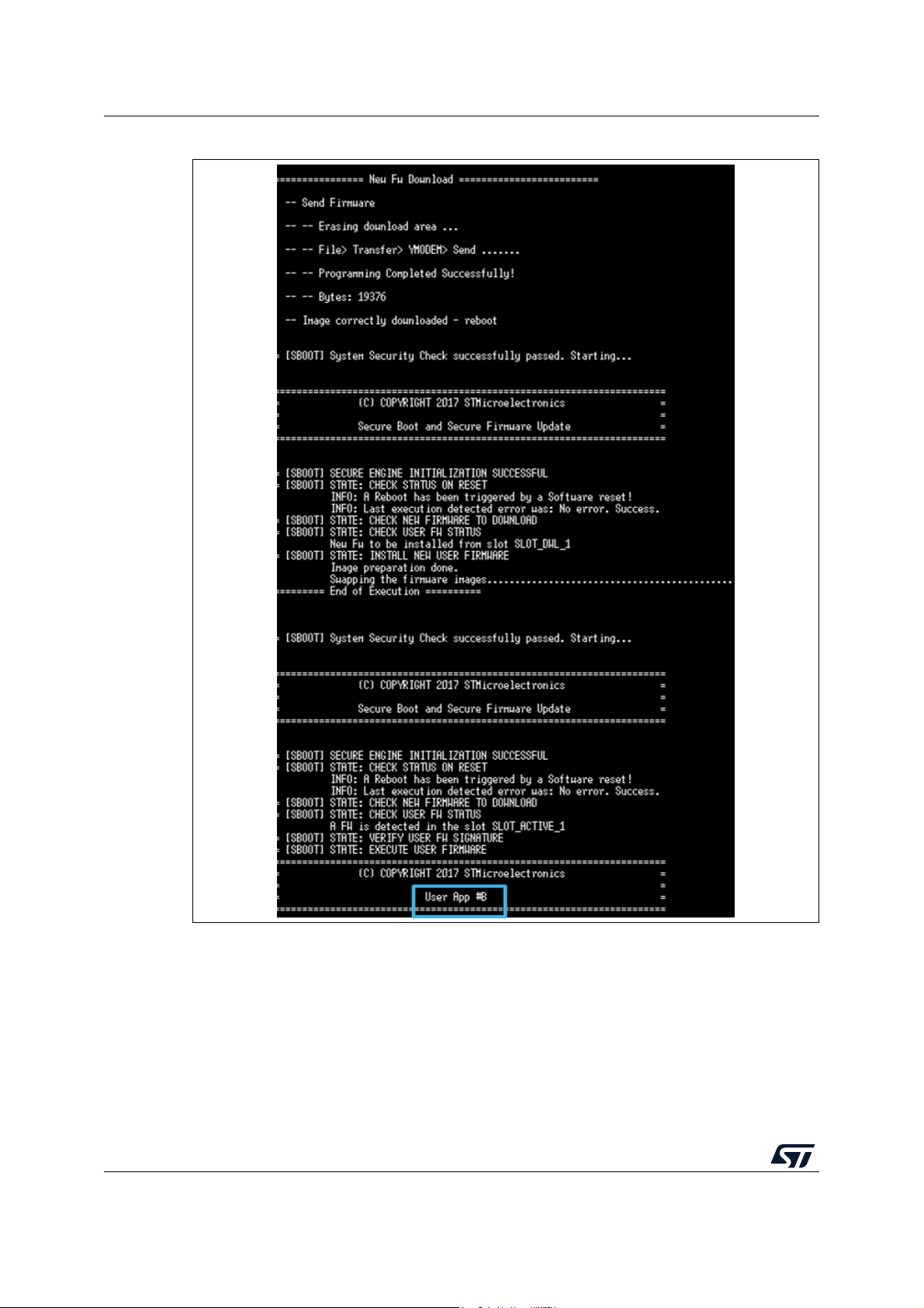
Step-by-step execution UM2262
Figure 30. Encrypted firmware download via a user application
58/104 UM2262 Rev 8
Page 59

UM2262 Step-by-step execution
8.5.2 Test protections
An example of the test protection menu is shown in Figure 31. The actual menu depends on
the STM32 Series.
Figure 31. User application test protection menu
The test protection menu is printed at each test attempt of a prohibited operation or error
injection as a function of the test run:
• CORRUPT IMAGE test (#1)
– Causes a signature verification failure at the next boot.
• Firewall tests (#2, #3)
– Causes a reset trying to access protected code or data (either in RAM or Flash)
• PCROP test (#4)
– Causes an error trying to access the PCROP region protecting the keys
• WRP test (#5)
– Causes an error trying to erase write protected code
• IWDG test (#6)
– Causes a reset simulating a deadlock by not refreshing the watchdog
• TAM P E R t e st (#7)
– Causes a reset if a tamper event is detected
– to generate a tamper event, the user must connect PA0 (CN7.28) to GND (It may
be enough to put a finger close to CN7.28).
Returning to the previous menu is obtained by pressing the x key.
8.5.3 Test Secure Engine user code
The version and size of the current user firmware are retrieved using a Secure Engine
service and printed in the console.
UM2262 Rev 8 59/104
102
Page 60
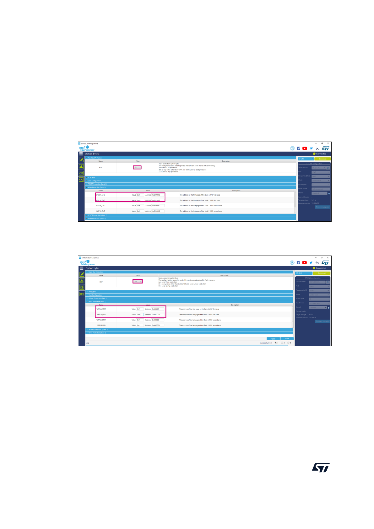
Step-by-step execution UM2262
8.6 Programming a new software when the securities are activated
After flashing binary in Flash with all securities enabled it is not possible anymore to update
SBSFU directly. You need first to disable the securities preventing the erasure of the SBSFU
software.
Launch the Cube Programmer application, and open the Option Bytes menu.
The Option Bytes menu looks like this (RDP Level 1 and WRP protection):
Figure 32. Option Bytes menu
Update the fields as follows. Set RDP to level 0 and set the WRP size to 0 and the start
address as 0xff. Then click on Apply for mass deletion of the FLASH to occur:
Figure 33. FLASH mass deletion
After this step, your FLASH is fully erased and you can program the software again.
60/104 UM2262 Rev 8
Page 61

UM2262 Understanding the last execution status message at boot-up
9 Understanding the last execution status message at
boot-up
Tabl e 6 lists the main error messages together with their explanation.
Error message Meaning
No error. Success. No problem is encountered.
Firewall error.
Table 6. Error messages at boot-up
A firewall exception occurred: some code or data protected by the firewall
has been addressed out of the Secure Engine context.
Watchdog error.
Memory fault. Memory fault is reported by the MPU fault handler.
Hard fault. Arm
Tampering fault. TAMPER-detection report.
Check protections error.
Check status on reset error. Error encountered while checking the status at boot (generic error).
Check new user FW to download
error.
Download new user FW error. Error encountered while performing a local download (generic error).
Verify user FW status error.
Decrypt user FW error.
Install user FW error. Error encountered during the installation of new firmware (generic error).
Verify user FW signature.
Resume FW installation error. Error encountered during the firmware installation procedure.
Execute user FW error. Error encountered while trying to launch the active firmware (generic error).
Watchdog expiry: the processing is too long and the watchdog has not been
reloaded in due time.
®
Cortex®-M hard fault exception.
Not used in the example code. This can be used to log errors when doing
the periodic verification of applied protection mechanisms.
Error encountered while checking if there is a local download request
(generic error).
Error encountered while verifying the status of the user firmware. This error
is reached when the Flash state does not allow determining the firmware
status (generic error).
Not used in the current example code. This can be used to log generic errors
related to the decrypt of a firmware. In the example, a more specific error is
used: “Decrypt failure.”
Error encountered while verifying the signature of the active firmware. In the
example code, the signature is already checked during the firmware status
check so this error is not supposed to be reported.
SE lock cannot be set.
FW too big.
Ymodem com failure.
Header authentication failed.
Error encountered while trying to configure Secure Engine in “Firmware
execution” mode (unprivileged mode) before starting the active firmware.
This error means that during a local download procedure the header
indicated a firmware size bigger than the capacity of the download slot.
During a local download procedure, the download operation did not
complete successfully (Ymodem protocol issue).
During a local download procedure, the header could not be authenticated
successfully. This error is reached only if the header stored in RAM is altered
(otherwise the download is bypassed without triggering a critical failure).
UM2262 Rev 8 61/104
102
Page 62

Understanding the last execution status message at boot-up UM2262
Table 6. Error messages at boot-up (continued)
Error message Meaning
Error encountered while decrypting the content of the download slot. This
Decrypt failure.
Signature check failure.
Flash error. Flash error is encountered during an installation procedure.
FWIMG pattern issue.
error reports a decryption or authentication issue as the final stage of the
decryption is a check of the signature.
Error encountered while verifying the signature of the decrypted firmware
during an installation procedure. In the example code, this error may not be
reached as a signature issue may be captured at the decrypt stage
(reporting “
Error encountered during an installation procedure: internal issue while
writing some SBSFU patterns.
Decrypt failure.”).
Error while swapping the images in
active and download slots.
Rollback process failure: Error
encountered during the rollback
installation process to the previous
firmware image
Firmware version rejected by antirollback check.
Unknown error.
Error encountered during an installation procedure: failure while swapping
the images (previous firmware and decrypted firmware).
Backed-up firmware not identified: the fingerprint of the previous firmware
image is not correct.
Error encountered during an installation procedure: the firmware version
cannot be accepted (newer firmware already installed or lower version than
min. allowed version).
Undocumented error (unexpected exception or unexpected state machine
issue).
62/104 UM2262 Rev 8
Page 63

UM2262 Secure Engine protected environment
Appendix A Secure Engine protected environment
The Secure Engine (SE) concept defines a protected enclave exporting a set of secure
functions executed in a trusted environment.
The following functionalities are provided by SE to the SBSFU application example:
• Secure Engine initialization function
• Secure cryptographic functions
– AES-GCM and AES-CBC decryption
– SHA256 hash and ECDSA verification
– Sensitive data (secret key, AES context) never leaves the protected environment
and cannot be accessed from unprotected code
• Secure read/write access to firmware image Information
– Read and write operation on a protected Flash area
– Access to this area is allowed only to protected code
• Secure image state handling
• Secure service to lock some functions in Secure Engine
– One-way lock mechanism: once locked, no way to unlock it except via a system
reset
– Once locked, functions execution is no more possible via the call gate mechanism
– Functionalities that are locked via the lock mechanism in Secure Engine example:
- Secure Engine initialization function
- Secure Encryption functions with OEM key
- Secure read/write access to firmware image Information
- Secure service to lock some functions in Secure Engine
Note: Functionalities exported by SE can be extended depending on final user applications needs
In the KMS variant, SE functionalities are extended with the secure key management
services providing cryptographic services to the user application through the PKCS #11
APIs (KEY ID-based APIs) are executed inside the Secure Engine protected environment.
User application keys are stored in this protected/isolated environment.
In the STSAFE-A variant, KMS is extended with STSAFE-A middleware, to provide access
to keys and services provided by the Secure Element through a standard interface.
Communication with the STSAFE-A110 is secured with symmetric keys stored in the
protected/isolated environment.
to deal with the firewall call gate mechanism and to provide the user with a set of secure
APIs, SE is designed with a two-level architecture, composed of SE Core and SE Interface.
The call gate concept and the two-level architecture apply also when using the MPU to
protect the Secure Engine, as described in Section
Isolation.
UM2262 Rev 8 63/104
A.2: MPU-based Secure Engine
102
Page 64

Secure Engine protected environment UM2262
A.1 Firewall-based Secure Engine Isolation
A.1.1 SE core call gate mechanism
The firewall is opened or closed using a specific ‘call gate’ mechanism: a single entry point
(placed at the 2nd word of the Code segment base address) must be used to open the gate
and to execute the code protected by the firewall. If the protected code is accessed without
passing through the call gate mechanism then a system reset is generated.
As the only way to respect the call gate sequence is to pass through the single call gate
entry point, therefore, if the application requires to have multiple functions protected by the
firewall and called from unprotected code outside it (e.g. encrypt and decrypt functions), a
way to select which of the internal functions to execute is needed. A solution is to use a
parameter to specify which function to execute, for instance, CallGate(F1_ID),
CallGate(F2_ID), and so on. According to the parameter, the right function is internally
called.
Figure 34. Firewall call gate mechanism
Caution: The code section must include all the code executed when the firewall is open. For instance,
if the call sequence is callgate->f1()->f1a()->f1b(), all the three functions f1(), f1a() and f1b()
must be included in the code section.
Figure 35 shows the steps to perform cryptographic operations (that require access to the
key) to respect the call gate mechanism.
For the cryptographic functions:
64/104 UM2262 Rev 8
Page 65

UM2262 Secure Engine protected environment
1. The SBSFU code calls the call gate function to open the firewall and to execute
protected code
2. The call gate function check parameters and securities and then calls the requested
Crypto function
3. The SE Crypto function calls an internal ReadKey function that moves the keys into the
protected section of SRAM1 and then uses them in the cryptographic operations.
Figure 35. Secure Engine call-gate mechanism
A.1.2 SE interface
Code protected by the firewall must be non-interruptible and it is up to the user code to
disable interrupts before opening the firewall.
SE interface provides a user-friendly wrapper handling the entrance and exit to a protected
enclave where the actual SE call gate function is executed as illustrated in Figure
36.
UM2262 Rev 8 65/104
102
Page 66

Secure Engine protected environment UM2262
Figure 36. Secure Engine interface
SE interface mechanism simplifies the control access to the call gate independent from user
implementation. SE interface APIs are shared with the user application, which therefore
executes sensitive operations (if not locked via the Secure Engine lock service) in a secure
way using the services provided by SE.
Interruption management inside the firewall isolated environment can be activated when low
latency on interruption handling is required. Examples are provided in the 2_Images_OSC
variant for 32L496GDISCOVERY and B-L475E-IOT01A boards. Section 7.3 of the
application note How to activate interruption management inside firewall isolated
environment (AN5056) describes in detail all the steps required to activate this option.
A.2 MPU-based Secure Engine Isolation
A.2.1 Principle
The MPU-based Secure Engine isolation relies on the concept of privileged and
unprivileged levels of software execution. The software must run in an unprivileged level of
execution by default (when SBSFU or the User application is running), except for very
specific actions like platform initialization or interrupt handling. This is described in
Figure
37.
66/104 UM2262 Rev 8
Page 67

UM2262 Secure Engine protected environment
Figure 37. SBSFU running in the unprivileged level of software execution for standard operations
When the software runs in an unprivileged mode, any attempt to access the Secure Engine
code or data results in an MPU fault: this ensures the isolation of the critical assets.
This isolation of the Secure Engine is implemented thanks to specific MPU regions as
shown in Tab le
Secure Engine code & constants
Secure Engine stack & VDATA
7.
Table 7. MPU regions for Secure Engine isolation
Region content Privileged permission Unprivileged permission
Read Only
(execution allowed)
Read Write
(not executable)
No access
No access
To run a Secure Engine service, the caller must first enter the privileged level of software
execution through a controlled access point. This is done using the concept of SE interface
(refer to Section
A.1.2: SE interface, keeping in mind that MPU protection replaces the
Firewall protection). It abstracts the request to get the privileged level of software execution:
this request consists of triggering a supervisor (SVC) call.
In the SBSFU example delivered in the X-CUBE-SBSFU Expansion Package, the SBSFU
application implements an SVC handler to catch this SVC call and process it with another
SE interface service to enter the Secure Engine via its call gate as shown in Figure
38.
Note: The SVC handler must be trusted because it is a key element of the Secure Engine access
control.
UM2262 Rev 8 67/104
102
Page 68
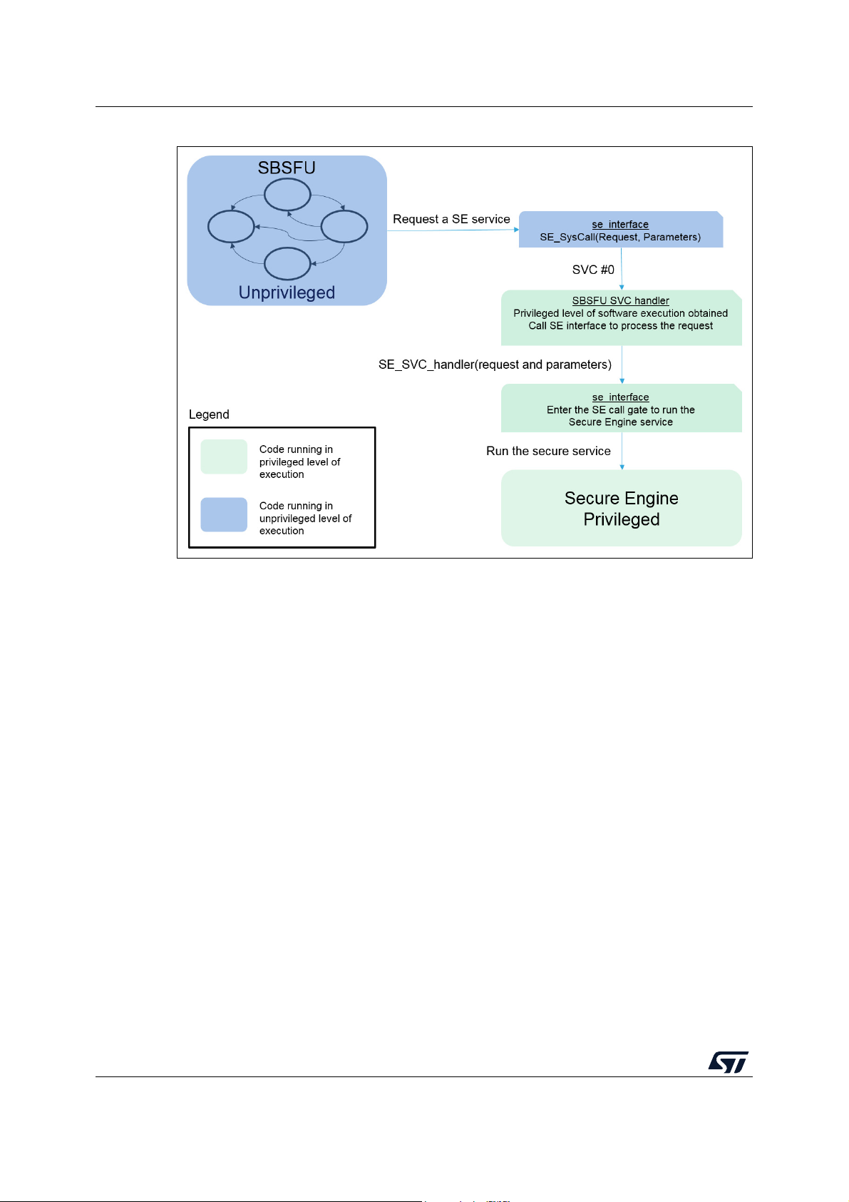
Secure Engine protected environment UM2262
Figure 38. SBSFU requesting a Secure Engine service
The SE call gate mechanism uses the concepts described in Section A.1.1: SE core call
gate mechanism to provide a unique entry point to the Secure Engine services. The
difference with Section
A.1.1 is that the MPU protection replaces the Firewall protection; the
constraints for the placement of the call gate code are only the MPU region constraints (the
call gate must be located in the privileged code region).
When the Secure Engine processing ends, the call gate concept provides a single exit point
and the SVC call return sequence applies. This return sequence brings the software back to
the unprivileged level of execution. Then, any further direct access to the Secure Engine
code and data generates an MPU fault.
The Secure Engine service exit is described in Figure 39.
68/104 UM2262 Rev 8
Page 69
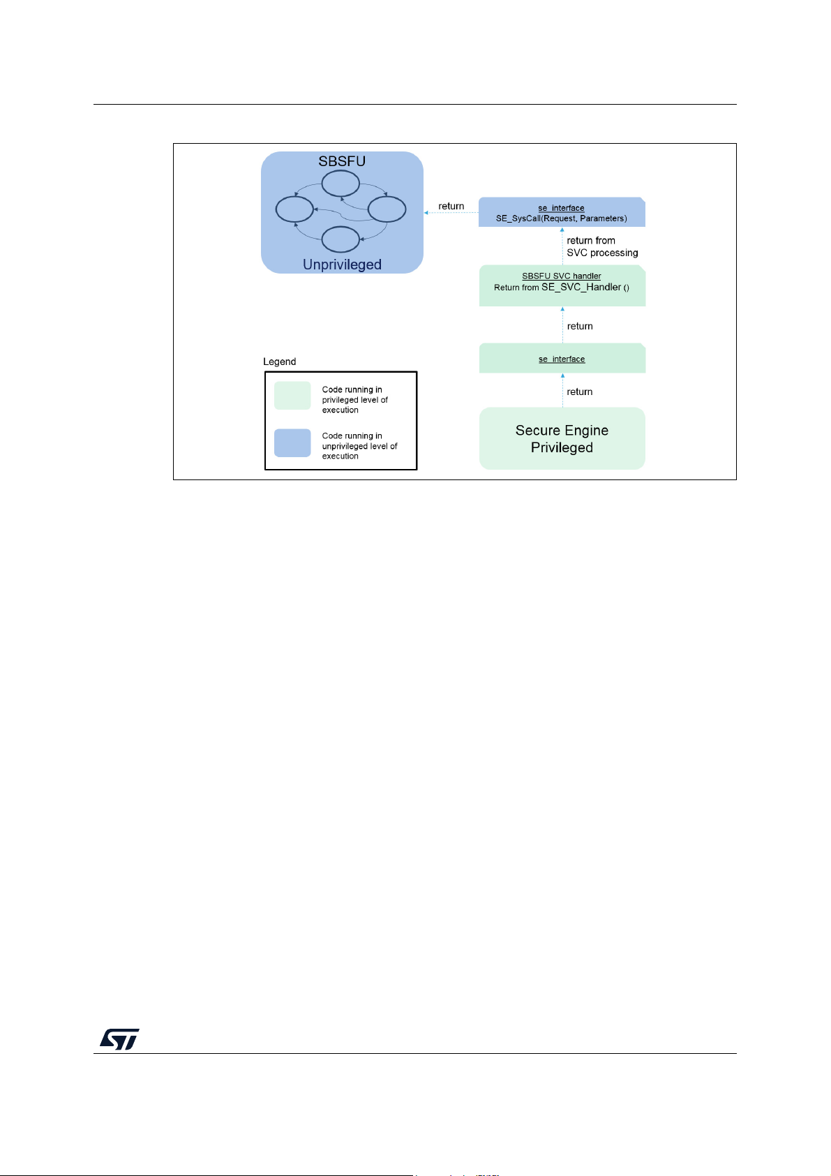
UM2262 Secure Engine protected environment
Figure 39. Exiting a Secure Engine service
A.2.2 Constraints
The MPU-based Secure Engine isolation relies fully on the fact that a privileged level of
software execution is required to access the Secure Engine services. The SVC handler is
the controlled access point to a privileged level of execution (this must be trusted code).
Additionally, any piece of code running in privileged mode must be trusted also (interrupt
routines, initialization code, and others) so that the controlled access point is not bypassed.
It is key to partition the software very carefully and avoid granting a privileged level of
execution when not required (the software must run in an unprivileged mode as much as
possible).
The MPU controls the Cortex®-M access to the memory. Any peripheral acting as a master
on the bus may access the Secure Engine code and data without triggering an MPU fault
(for instance a DMA peripheral). It is therefore required to make sure that only trusted code
can program these peripherals. For instance, in the X-CUBE-SBSFU example for
32F413HDISCOVERY, an MPU region covers the DMA registers to make sure it is not
possible to program these peripherals in the unprivileged mode of execution: only the
privileged code can configure the DMAs.
Last but not least, for the STM32F4 Series and the STM32F7 Series, the Secure Engine
protection is ensured only as long as the required MPU settings are maintained. If the userapplication code is not fully trusted or if a bug can be exploited by a hacker, the MPU
configuration must be maintained during User application execution.
This latter constraint does not exist for the STM32 Series with secure user memory. Before
launching the user application, the MPU protection is disabled and the secure user memory
protection is activated. When secured, any access to the securable memory area (fetch,
read, programming, erase) is rejected, generating a bus error. All the code and secrets
located inside secure user memory (a protected environment) is fully hidden.
UM2262 Rev 8 69/104
102
Page 70

Dual-slot configuration UM2262
Appendix B Dual-slot configuration
Some SBSFU application examples handle two slots located in internal Flash memory.
B.1 Elements and roles
• Active slot:
– This slot contains the active firmware (Firmware header + firmware). This is the
user application that is launched at boot time by SBSFU (after verifying its
validity).
• Download slot:
– This slot is used to store the downloaded firmware (Firmware header + encrypted
firmware) to be installed at the next reboot.
– In the case of a partial image, the size of this slot can be lower than the size of the
active slot (which contains the full image). The download slot can be sized
according to the maximum possible partial image.
• Swap region:
– This is a Flash area used to swap the content of active and download slots.
– Nevertheless, this area is not a buffer used for every swap of the Flash sector. It is
used to move the first sector, hence creating a shift in Flash allowing swapping the
two slots sector by sector.
Figure 40 represents the mapping on NUCLEO-L476RG. The mapping order for slots and
swap elements depends on the STM32 Series:
• For The STM32 Series with secure user memory, the active slot header must be
mapped just after the SBSFU code to be protected by the secure user memory.
• For the STM32L4 Series, the firewall code and data (active slot header) segments
must be located at the same offset from the base address in each bank (ensuring that
secrets are always protected even if the banks are swapped).
70/104 UM2262 Rev 8
Page 71

UM2262 Dual-slot configuration
Figure 40. Internal user Flash mapping: Example of the NUCLEO-L476RG with 512-byte headers
UM2262 Rev 8 71/104
102
Page 72
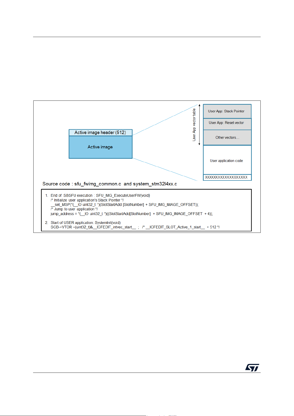
Dual-slot configuration UM2262
B.2 Mapping definition
The mapping definition is located in the Linker_Common folder for each example. Figure 41
shows how to find information such as slot size and SBSFU code size in the NUCLEOL476RG example.
To start the application, SBSFU initializes the SP register with the user application stack
pointer value, then jumps to the user application reset vector (refer to Figure
Figure 41. User application vector table (example of the STM32L4 Series)
41).
72/104 UM2262 Rev 8
Page 73

UM2262 Single-slot configuration
Appendix C Single-slot configuration
Some SBSFU application examples handle one single slot located in internal Flash memory.
This mode of operation allows maximizing the user firmware size by:
• Reducing the SBSFU footprint in Flash
• Allocating more Flash space for the user application
These benefits come at the cost of some features:
• Safe firmware image programming cannot be ensured: as soon as the installation is
interrupted (power off), the firmware update process must be restarted from the
beginning (including the download phase).
• No rollback is possible if the new firmware image is not correct.
• The user application cannot download a new firmware image: the local download
procedure is the only way to update the active user code.
C.1 Elements and roles
Active slot:
• This slot contains the active firmware (Firmware header + firmware). This is the user
application that is launched at boot time by SBSFU (after verifying its validity).
• This slot is directly updated when a new firmware image is downloaded and installed
(after firmware header verification)
C.2 Mapping definition
The mapping definition is located in the Linker_Common folder for each example. Figure 41
shows how to find information such as slot size and SBSFU code size in the NUCLEOL432KC example.
To start the application, SBSFU initializes the SP register with the user application stack
pointer value, then jumps to the user application reset vector (refer to Figure
application vector table (example of the STM32L4 Series)).
41: User
UM2262 Rev 8 73/104
102
Page 74

Cryptographic schemes handling UM2262
Appendix D Cryptographic schemes handling
Four cryptographic schemes are provided as examples to illustrate the cryptographic
operations. The default cryptographic scheme uses both symmetric (AES-CBC) and
asymmetric (ECDSA) cryptography. So, it handles a private key (AES128 private key) as
well as a public key (ECC key).
Two alternate schemes are provided. They are selected using a SECoreBin compiler switch
(named ‘SECBOOT_CRYPTO_SCHEME’).
The X509 certificate-based asymmetric scheme is configured in the STSAFE-A variant and
the KMS variant for the B-L4S5I-IOT01A board.
D.1 Cryptographic schemes contained in this package
Tabl e 8 shows the cryptographic scheme selected with the SECBOOT_CRYPTO_SCHEME
compiler switch.
SECBOOT_CRYPTO_SCHEME value Authentication Confidentiality Integrity
Table 8. Cryptographic scheme list
SECBOOT_ECCDSA_WITH_AES128_CBC_SHA256 (default) ECDSA AES128-CBC SHA256
SECBOOT_ECCDSA_WITH_AES128_CTR_SHA256
SECBOOT_ECCDSA_WITHOUT_ENCRYPT_SHA256 ECDSA None
SECBOOT_AES128_GCM_AES128_GCM_AES128_GCM
SECBOOT_X509_ECDSA_WITHOUT_ENCRYPT_SHA256 ECDSA
1. This cryptographic scheme is selected for products with external Flash and OTFDEC support.
2. The SBSFU project must also be configured to deal with a clear firmware image by setting the compiler switch
SFU_IMAGE_PROGRAMMING_TYPE to the value SFU_CLEAR_IMAGE.
3. For the symmetric cryptographic scheme, it is highly recommended to configure a unique symmetric key for each product.
(1)
(3)
ECDSA AES128-CTR SHA256
AES-GCM
None
(2)
(2)
SHA256
SHA256
74/104 UM2262 Rev 8
Page 75

UM2262 Cryptographic schemes handling
D.2 Asymmetric verification and symmetric encryption schemes
D.2.1 Cryptographic schemes with full software implementation
These schemes (SECBOOT_ECCDSA_WITH_AES128_CBC_SHA256,
SECBOOT_ECCDSA_WITHOUT_ENCRYPT_SHA256) are implemented for firmware
decryption and verification as illustrated in Figure
Figure 42. Asymmetric verification and symmetric encryption
42.
UM2262 Rev 8 75/104
102
Page 76

Cryptographic schemes handling UM2262
D.2.2 AES CTR decryption with OTFDEC peripheral
The OTFDEC peripheral embedded in the STM32H7B3 Series offers the possibility to
decrypt the content directly with a low latency penalty and without the need for SRAM
allocation. The OTFDEC is a hardware block that decrypts on-the-fly bus (AHB) traffic
based on the read-request address information.
Scheme SECBOOT_ECCDSA_WITH_AES128_CTR_SHA256 is implemented for firmware
decryption and verification as illustrated in Figure
Figure 43. AES CTR decryption with OTFDEC peripheral
43.
76/104 UM2262 Rev 8
Page 77
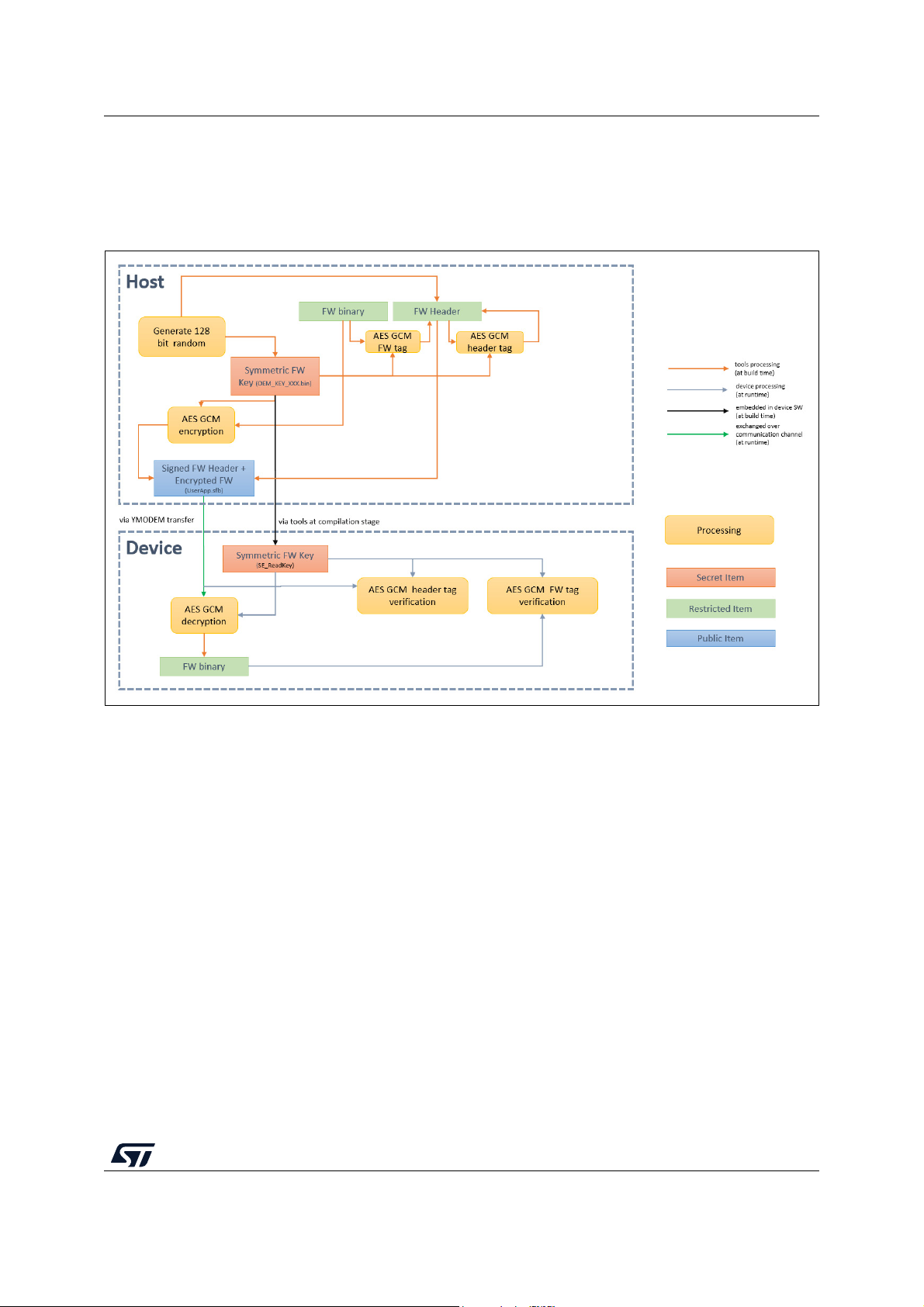
UM2262 Cryptographic schemes handling
D.3 Symmetric verification and encryption scheme
This scheme (SECBOOT_AES128_GCM_AES128_GCM_AES128_GCM) is implemented
for firmware decryption and verification as illustrated in Figure
Figure 44. Symmetric verification and encryption
44.
UM2262 Rev 8 77/104
102
Page 78
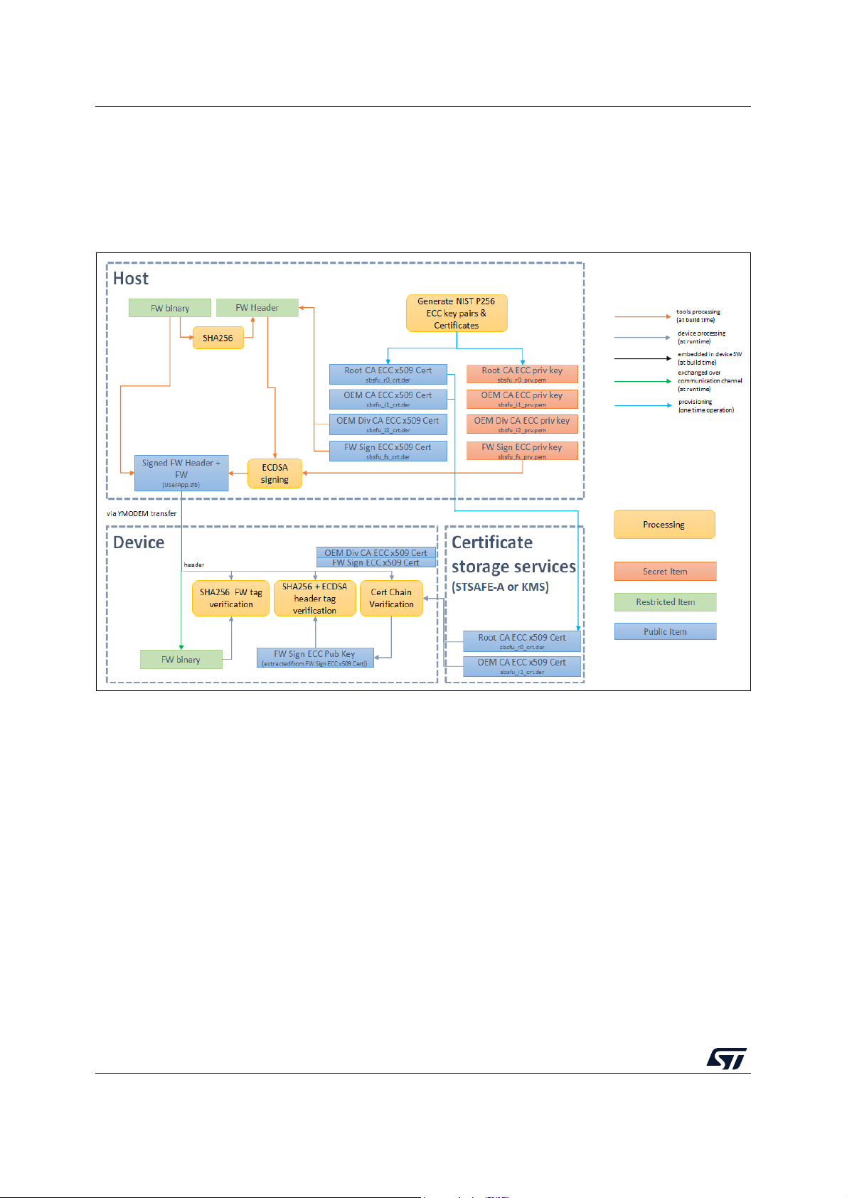
Cryptographic schemes handling UM2262
D.4 X509 certificate-based asymmetric scheme without firmware
encryption
This scheme (SECBOOT_X509_ECDSA_WITHOUT_ENCRYPT_SHA256) is implemented
for firmware verification as illustrated in Figure
Figure 45. X509 asymmetric verification
45.
The X509 certificate-based asymmetric scheme makes use of a chain of X509 certificates to
deliver the public key used to verify the firmware header signature.
In the example provided, two certificates (the Root CA and OEM CA (first intermediate CA))
are embedded in secure element STSAFE-A110, or KMS non-volatile memory, while the
second intermediate CA and leaf certificate (firmware signing certificate) are delivered as
part of the firmware header.
78/104 UM2262 Rev 8
Page 79
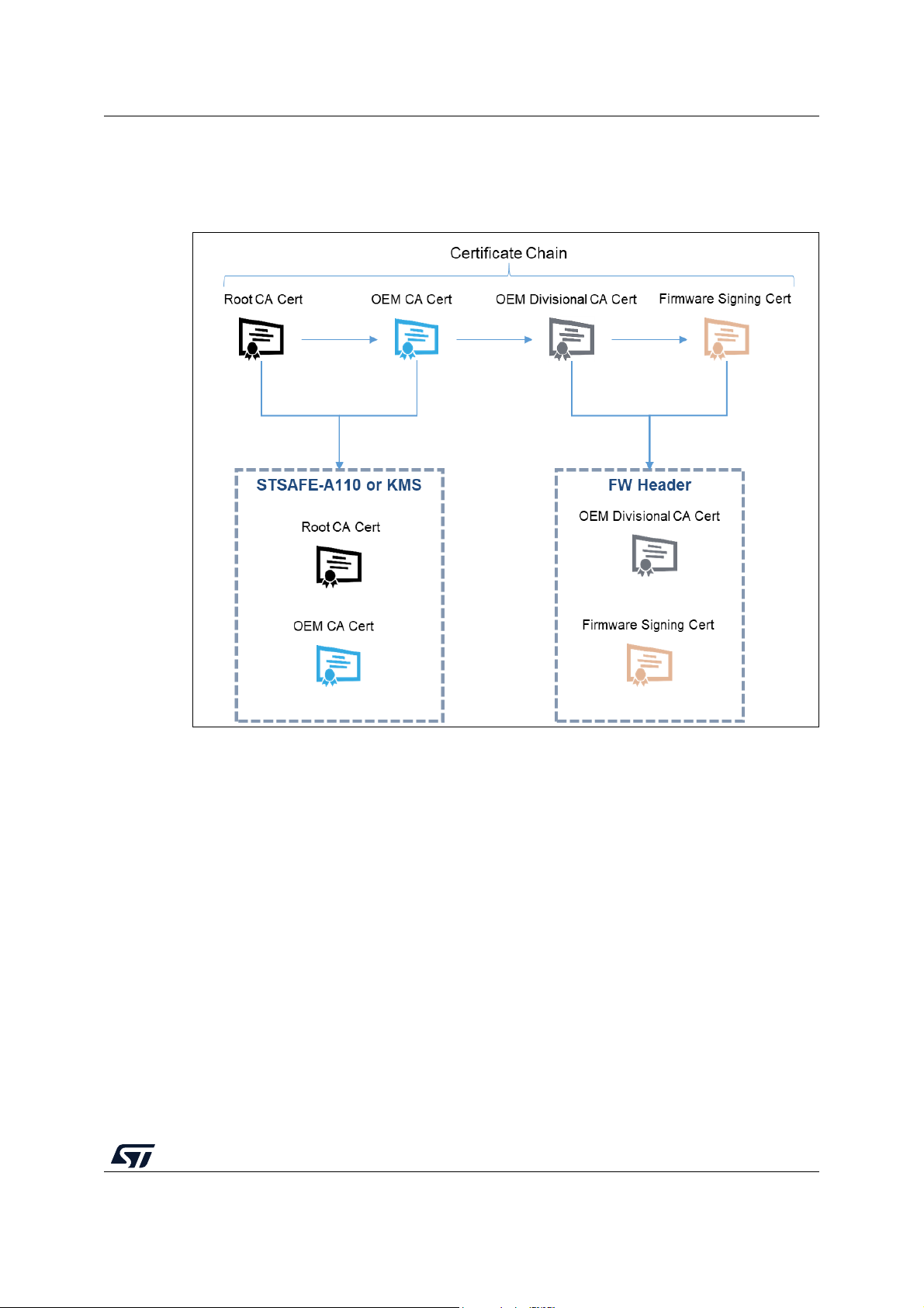
UM2262 Cryptographic schemes handling
D.5 Asymmetric verification and symmetric encryption schemes
Figure 46. Certificate chain
to use the public key contained in the leaf certificate, the certificate chain is first verified by
the SBSFU code to ensure that the delivered firmware signing public key is authentic. Once
the certificate chain is verified, the firmware signing public key is used to verify the firmware
header signature.
UM2262 Rev 8 79/104
102
Page 80

Cryptographic schemes handling UM2262
D.6 Secure Boot and Secure Firmware Update flow
Figure 47 and Figure 48 indicate how the cryptographic operations (asymmetric
cryptographic scheme with FW encryption) are integrated into the SBSFU execution boot
flows.
Figure 47. SBSFU dual-slot boot flows
80/104 UM2262 Rev 8
Page 81

UM2262 Cryptographic schemes handling
Figure 48. SBSFU single-slot boot flows
UM2262 Rev 8 81/104
102
Page 82

Firmware image preparation tool UM2262
Appendix E Firmware image preparation tool
The X-CUBE-SBSFU STM32Cube Expansion Package is delivered with the prepareimage
firmware image preparation tool allowing:
• Taking into account the selected cryptographic scheme and keys
• Encrypting the firmware image when required
• Generating partial firmware image, by extracting binary differences between two full
images
• Generating the firmware header with all the data required for the authentication and
integrity checks
The prepareimage tool is delivered in two formats:
• Windows® executable: the standard Windows® command interpreter is required
• Python™ scripts: a Python™ interpreter as well as the elements listed in
Middlewares\ST\STM32_Secure_Engine\Utilities\KeysAndImages\readme.txt are
required
The Windows® executable enables quick and easy use of the package with all three
predefined cryptographic schemes. The Python™ scripts, delivered as source code, offer
the possibility to define additional cryptographic schemes flexibly.
Note: Refer to Appendix F and Appendix G for KMS and STSAFE-A specificities.
E.1 Tool location
The Python™ scripts as well as the Windows® executable are located in the Secure Engine
component, in folder Middlewares\ST\STM32_Secure_Engine\Utilities\KeysAndImages.
E.2 Inputs
The package is delivered with some default keys and cryptography settings in folder
Applications\2_Images\2_Images SECoreBin\Binary.
Each of the following files can be used as such, or modified to take the user settings into
account:
• ECCKEY1.txt: private ECC key in PEM format. It is used to sign the firmware header.
This key is not embedded in the SECoreBin, only the corresponding public key is
generated by the tools in the se_key.s file
• nonce.bin: this is either a nonce (when AES-GCM is used) or an IV (when AES-CBC is
used). This value is added automatically by the tools to the firmware header.
• OEM_KEY_COMPANY1_key_AES_CBC.bin: symmetric AES-CBC key. This key is
used for the AES-CBC encryption and decryption operations and is embedded in the
se_key.s file. This file is exclusive with OEM_KEY_COMPANY1_key_AES_GCM.bin
• OEM_KEY_COMPANY1_key_AES_GCM.bin: symmetric AES-GCM key. This key is
used for all AES-GCM operations and is embedded in the se_key.s file. This file is
exclusive with OEM_KEY_COMPANY1_key_AES_CBC.bin
82/104 UM2262 Rev 8
Page 83

UM2262 Firmware image preparation tool
The tool uses the appropriate set of files based on the cryptographic scheme selected using
SECBOOT_CRYPTO_SCHEME in
Applications\2_Images\2_Images SECoreBin\Inc\se_crypto_config.h.
E.3 Outputs
The tool generates:
• The se_key.s file compiled in the SECoreBin project: this file contains the keys (private
symmetric key and public ECC key when applicable) embedded in the device and the
code to access them. When running the tool from the IDE, this file is located in
Applications\2_Images \2_Images SECoreBin\EWARM\. In the case of multiple images
configuration, one set of keys is generated per image.
• An sfb file packing the user firmware header and the encrypted user firmware image
(when the selected cryptographic scheme enables user firmware encryption). When
running the tool from the IDE, this file is generated in
Applications\2_Images\2_Images UserApp\Binary\.
• A bin file concatenating the SBSFU binary, UserApp binary, and active FW image
header. Flashing this file into the device with a flasher tool makes the UserApp
installation process simple since the FW header and FW image are already correctly
installed. It is not needed to use the SBSFU application for installing the UserApp.
For STM32 devices with OTFDEC support and external Flash, two separate binary files
are generated:
– A first binary concatenating SBSFU binary and active FW image header
(SBSFU_UserApp_Header.bin) to be programmed into the internal Flash memory.
– A second binary (UserApp.sfb) to be Programmed into the external memory at the
active slot start address.
Caution:
– Before programming the bin file into the device, a mass deletion must be
performed. to detect any malicious software, SBSFU verifies at startup that there
is no additional code after UserApp in the active slot.
– When the active slot is located in external Flash, the active slot must be erased
before programming the bin file.
• Two log files, output.txt, located in
Applications\2_Images \2_Images SECoreBin\EWARM\
and in
Applications\2_Images\2_Images UserApp\EWARM
to trace the executions of prebuild.bat and postbuild.bat.
E.4 IDE integration
The prepareimage tool is integrated with the IDEs as Windows® batch files for:
• Pre-build actions for the SECoreBin application: at this stage, the cryptographic keys
are managed
• Post-build actions for the UserApp application: at this stage, the firmware image is built
UM2262 Rev 8 83/104
102
Page 84

Firmware image preparation tool UM2262
When compiling with the IDE, the keys and the firmware image are handled. No extra action
is required from the user. At the end of the compilation steps:
• The required keys are embedded in the SECoreBin binary
• The firmware image to be installed is generated in the proper format, with the
appropriate firmware header, as an sfb file. This sfb file can be transferred over the
Ymodem protocol for installation by SBSFU.
• The bin file that can be flashed for the test of UserApp (SBFU_UserApp.bin).
The batch files integrating the tool in the IDE are located in the folder
Applications\2_Images\2_Images SECoreBin\EWARM:
• prebuild.bat: invoking the tool to perform the pre-build actions when compiling the
SECoreBin project
• postbuild.bat: invoking the tool to perform the post-build actions when compiling the
UserApp project
These batch files allow seamless switching from the Windows® executable variant to the
Python™ script variant of the prepareimage tool. The procedure is described in the files
themselves.
E.5 Partial Image
A partial image contains only the binary portion of the new firmware image to install, versus
the active firmware image.
Partial-image usage presents various benefits:
• Smaller firmware image to download (reduced download duration)
• Faster firmware image installation
• Memory mapping optimization, with possibly smaller download slot (maximum size of
partial image) and bigger active slot (maximum size of the full image)
This feature is available on the dual-slot variant only (not available on the single-slot
variant).
For the partial-image feature, the header structure includes two instances of the FW tag:
• Partial FW tag: tag of the partial image only. This tag is checked by SBSFU during the
image installation phase.
• FW tag: tag of the full image (after the installation of the partial image). This tag is
checked by SBSFU during the image boot phase.
The prepareimage tool can be used to generate partial firmware image, starting from the
active image and the new firmware image to install:
1. Perform first a binary comparison between the two full images in clear
2. Then apply the usual image preparation procedure
Refer to the detailed procedure Example for partial update described in the readme.txt file of
the prepareimage tool
(Middlewares\ST\STM32_Secure_Engine\Utilities\KeysAndImages\readme.txt).
84/104 UM2262 Rev 8
Page 85
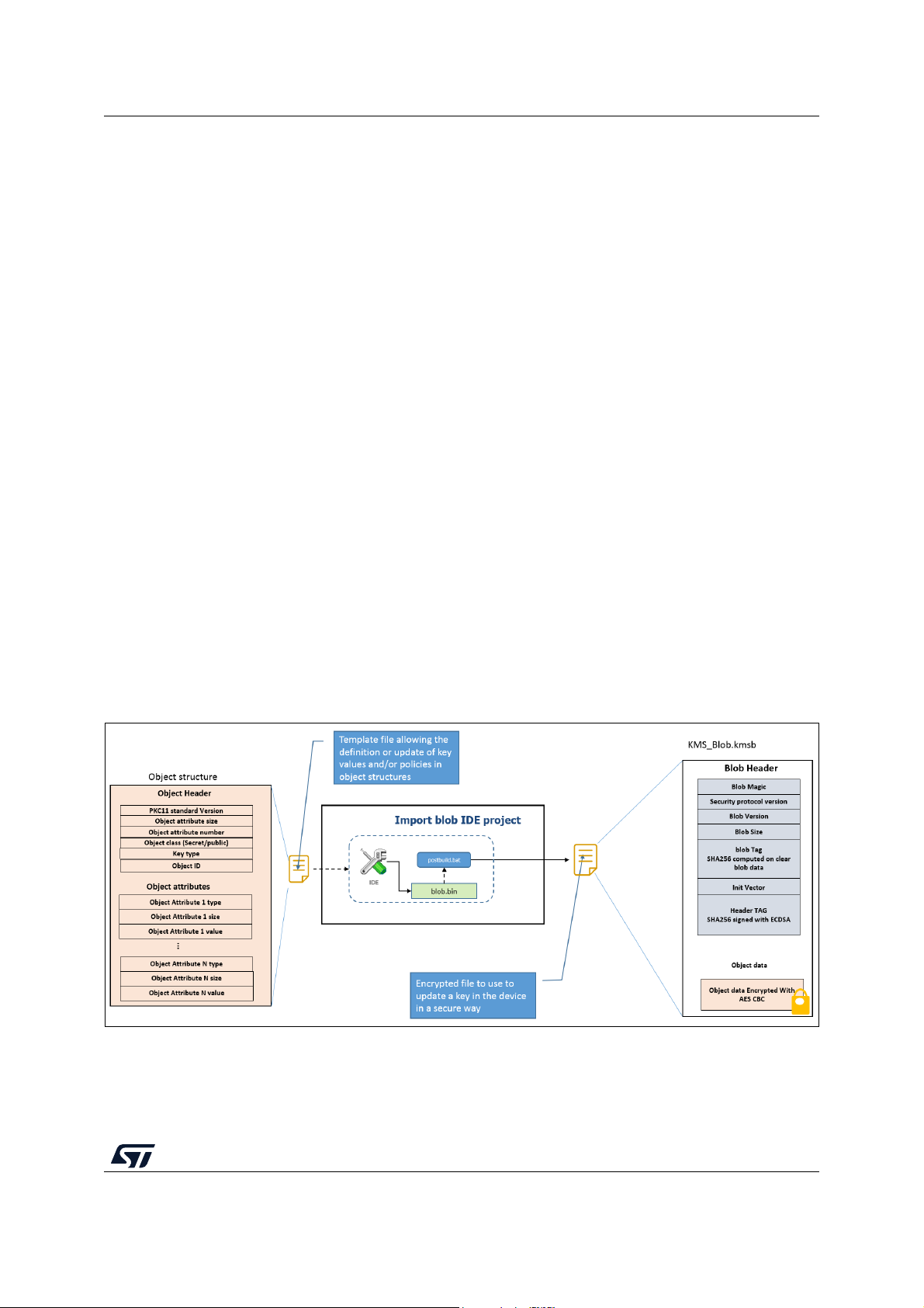
UM2262 KMS
Appendix F KMS
F.1 Key update process description
PKCS #11 APIs manage keys through objects containing a different type of information:
• Object header: giving information about the object itself, such as attribute size, number
of attributes and object ID
• Object attributes: such as type, size, and value
Static embedded keys are embedded in the code and cannot be modified. On the contrary,
updatable keys can be modified in an NVM storage located inside the protected/isolated
environment:
• An updatable key with dynamic ID can be created via a secure object creation
procedure running inside the protected/isolated environment ensuring that the key
remains inside the protected/isolated environment (key value is stored in the NVM
storage and only the object ID is returned to the application).
• An updatable key with static ID can be updated in the NVM storage via a secure update
procedure using static embedded root keys (authenticity check, data integrity check
and data decryption). It means that the key must be provided to KMS in a specific
format to ensure key authenticity, integrity, and confidentiality. KMS example is
provided with a tool allowing to automatically generate the encrypted object based on
ECDSA asymmetric cryptography for data authenticity/integrity verification and based
on AES-CBC symmetric cryptography for data confidentiality. Once an encrypted
object is downloaded into the device, the SBSFU application detects it at the next
system reset and SBSFU application processes it via the KMS secure update
procedure (C_STM_ImportBlob() function).
Figure 49 and Figure 50 illustrate the key creation and update procedure.
Figure 49. Encrypted object creation
UM2262 Rev 8 85/104
102
Page 86
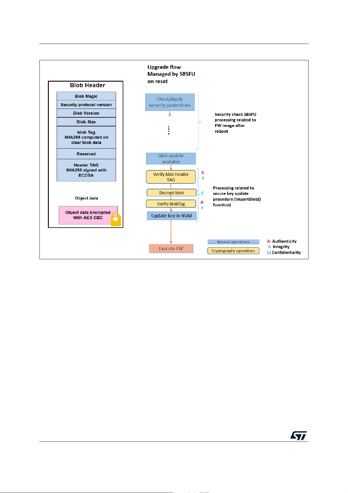
KMS UM2262
Figure 50. Secure update procedure
F.2 SBSFU static keys generation
With KMS middleware integration, SBSFU keys are no more stored in a section under
PCROP protection but inside the KMS code running in the secure enclave as shown in
Figure
51. During the SECoreBin compilation stage, prebuild.bat updates SBSFU static
embedded keys inside kms_platf_objects_config.h located in Applications\2_Images
\2_Images SECoreBin\EWARM\ (instead of the se_key.s file update done in the standard
variant).
86/104 UM2262 Rev 8
Page 87
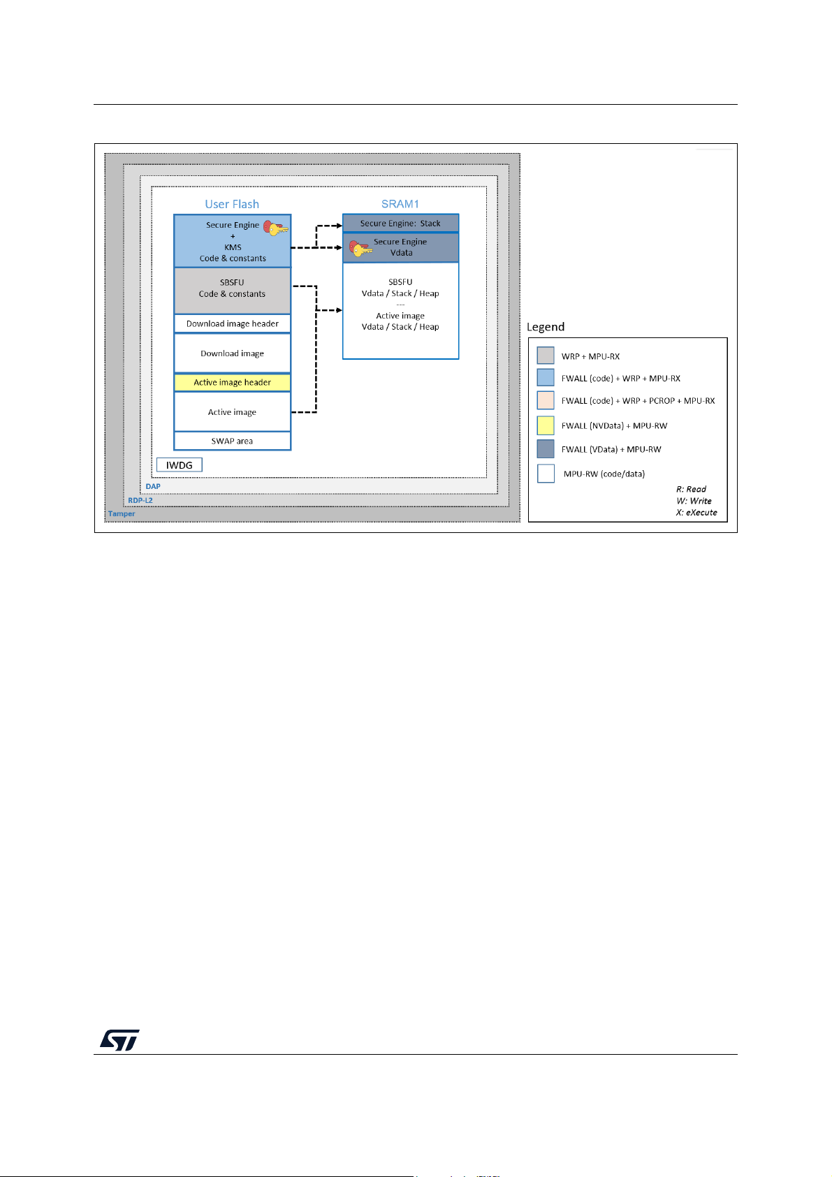
UM2262 KMS
Figure 51. KMS key storage
F.3 Using KMS & X509 cryptographic scheme
This cryptographic scheme shown in Figure 52 is based on a four-certificate chain principle:
1. Root CA certificate: root certificate to be provisioned once inside KMS embedded keys
(as described in Section
2. OEM CA certificate: first intermediate certificate from the OEM to be provisioned once
inside KMS embedded keys (as described in Section
3. OEM Divisional CA certificate: second intermediate certificate from the OEM to be
inserted inside the header of each new firmware image
4. Firmware Signing certificate: firmware signing certificate from the OEM to be inserted
inside the header of each new firmware image
F. 2 )
F. 2 )
UM2262 Rev 8 87/104
102
Page 88

KMS UM2262
Figure 52. Certificate chain overview
Note: For certificates generation details, refer to Section G.2.
F.4 UserApp menu
A specific menu is added providing examples using KMS services exported services
through a standard PKCS #11 interface: AES-GCM/CBC encryption/decryption, RSA
signature/verification, key provisioning, AES ECB key derivation, ECDSA key pair
generation, and ECDH Diffie-Hellman key derivation.
88/104 UM2262 Rev 8
Page 89

UM2262 KMS
Figure 53. KMS menu
UM2262 Rev 8 89/104
102
Page 90

SBSFU with STM32 and STSAFE-A110 UM2262
Appendix G SBSFU with STM32 and STSAFE-A110
G.1 Introduction to STSAFE-A110
STSAFE-A110 is a tamper-resistant secure element (Hardware Common Criteria EAL5+
certified) used to host X509 certificates and keys and perform verifications that are used for
firmware image authentication during Secure Boot and Secure Firmware Update
procedures.
STSAFE-A110 is connected to STM32 using the I2C hardware interface. Paring keys must
be provisioned inside STSAFE-A110 and STM32 to secure the system:
• Host_Mac_Key: a symmetric key used to pair a specific STM32 with a specific
STSAFE-A110 to establish secure communication between STM32 and STSAFE-A110
using CMAC calculation (block-cipher-based MAC)
• Host_Cipher_Key: a symmetric key used to encrypt I
STM32 and STSAFE-A110 to establish a secure communication channel
To combine an STSAFE-A110 with an STM32 for an SBSFU application, cryptographic
scheme X509 certificate-based asymmetric scheme without firmware encryption is used
(refer to Appendix D: Cryptographic schemes handling for more details). This cryptographic
scheme is based on a four-certificate chain principle:
• Root CA Cert: root certificate to be provisioned once inside the STSAFE-A110
• OEM CA Cert: first intermediate certificate from the OEM to be provisioned once inside
the STSAFE-A110
• OEM Divisional CA Cert: second intermediate certificate from the OEM to be inserted
inside the header of each new firmware image
• Firmware Signing Cert: firmware signing certificate from the OEM to be inserted inside
the header of each new firmware image
2
C communication between
90/104 UM2262 Rev 8
Page 91

UM2262 SBSFU with STM32 and STSAFE-A110
Figure 54. Certificate chain overview
As explained above, the STM32, STSAFE-A110, and firmware image must be provisioned
with some keys and or certificates:
• STM32: pairing keys must be inserted inside the SBSFU application code (inside the
part that is executed inside the protected environment) to be able to communicate
securely with an STSAFE-A110 component
(a)
.
• STSAFE-A110:
– Pairing keys must be provisioned inside the STSAFE-A110 to be able to
communicate securely with an STM32 component
(a)
. Pairing keys are stored in
se_key.s (section SE_ReadKey), as executable code, located in the project
2_Images_STSAFE\2_Images_SECoreBin.
– Root CA Cert and OEM CA Cert must be provisioned inside the STSAFE-A110 to
be able to verify OEM Divisional CA Cert and Firmware Signing Cert that are
received as part of the header of the new firmware image to be installed on the
STM32
• Firmware image: OEM Divisional CA Cert and Firmware Signing Cert must be inserted
in the header of the new firmware image to be installed on the STM32
(a)
.
(a)
.
a. A full code example for the provisioning of keys and certificates inside STSAFE-A110 is
provided. The project is called ‘STSAFE-A Provisioning’. More information in
Section G.3.
UM2262 Rev 8 91/104
102
Page 92

SBSFU with STM32 and STSAFE-A110 UM2262
Figure 55. Pairing key and certificate provisioning overview
G.2 Certificate generation
Generation of the certificates is done using openssl via a set of batch files provided in the
STSAFE-A110 project example variant as shown in Figure
• GEN_SBSFU_SAMPLE_ROOT_CA_ECC_NIST_P256.bat: generates the Root CA
public and private ECC keys and a self-signed root certificate.
• GEN_SBSFU_SAMPLE_INTER1_OEM1_CA_ECC_NIST_P256.bat: generates the
First Intermediate CA (OEM CA) ECC key pair and a certificate signed by the RootCA.
• GEN_SBSFU_SAMPLE_INTER2_OEM1_CA_ECC_NIST_P256.bat: generates the
Second Intermediate CA (OEM Divisional CA) ECC key pair and a certificate signed by
the OEM CA.
• GEN_SBSFU_SAMPLE_FWSIGN_OEM1_CA_ECC_NIST_P256.bat: generates the
Firmware Signing ECC key pair and a certificate signed by the OEM Divisional CA.
56:
92/104 UM2262 Rev 8
Page 93
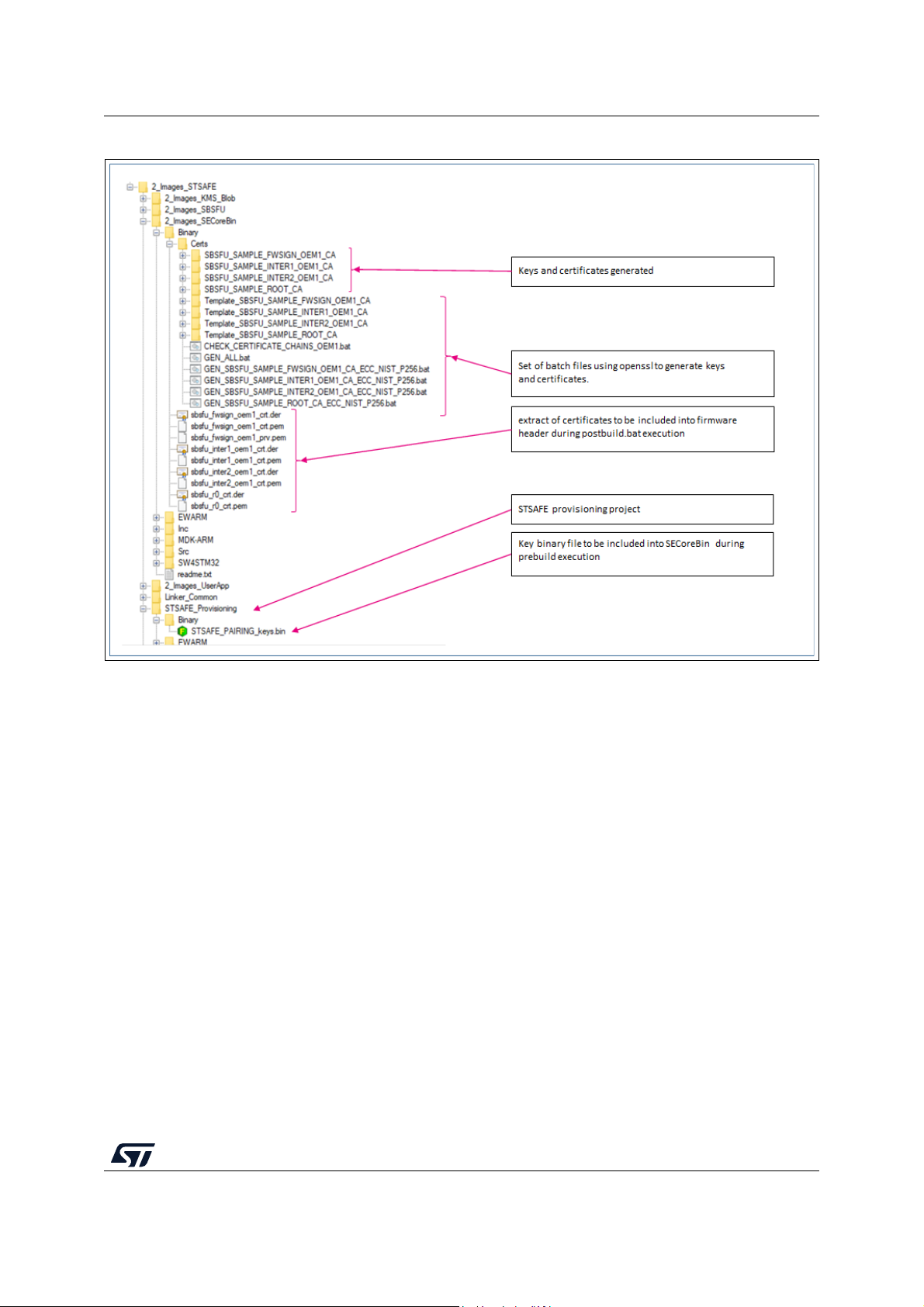
UM2262 SBSFU with STM32 and STSAFE-A110
Figure 56. Batch files using openssl
G.3 STSAFE-A110 provisioning
To provision STSAFE-A110 with pairing keys and certificates that are used in the context of
the SBSFU application example, a provisioning tools application project is provided as an
example in the X-CUBE-SBSFU package (2_Images_STSAFE\STSAFE_Provisioning).
STSAFE_PAIRING_keys.bin must be updated to provide the same keys in the STM32.
Refer to the readme file in this project to get details on the procedure and the steps
executed by this project.
G.4 STM32 and firmware image provisioning
To provision the STM32 with the pairing keys and insert the certificates in the firmware
image headers, the prepare image tool concept of the X-CUBE-SBSFU Expansion Package
is used (refer to Appendix E: Firmware image preparation tool for more details):
• IDE pre-build script is used to insert pairing keys inside the SBSFU code
• IDE post-build script is used to insert certificated inside the firmware image header
UM2262 Rev 8 93/104
102
Page 94

SBSFU with STM32 and STSAFE-A110 UM2262
Figure 57. Provisioning in STM32 and firmware image
G.5 STSAFE-A110 ordering
To use the STSAFE-A110 in the context of the SBSFU application example, the STSAFEA110 must be personalized at the STMicroelectronics manufacturing stage with some
specific data (such as private keys for instance) corresponding to a profile called ‘Generic
sample profile or SPL2’. This profile of personalization is described inside the application
note STSAFE-A110 generic sample profile description (AN5435) that can be found at
https://www.st.com/en/secure-mcus/stsafe-a110.html#resource.
Board B-L4S5I-IOT01A (https://www.st.com/en/evaluation-tools/b-l4s5i-iot01a.html) already
contains STSAFE-A110 soldered onboard and loaded with generic sample profile as
described in AN5435.
SPL02 profile contains:
The order codes (sales references) for the STSAFE-A110, which are:
- STSAFA110S8SPL02 (SO8N package)
- STSAFA110DFSPL02 (UFDFPN8 package).
94/104 UM2262 Rev 8
Page 95

UM2262 STM32WB Series specificities
Appendix H STM32WB Series specificities
H.1 Compilation process
A specific project (Loader) implementing the firmware download feature (over the Ymodem
protocol) is provided to make easier the integration of over-the-air download capability
(Bluetooth
Figure 58 outlines the additional step 0 to compile then integrate the Loader into SBSFU
during the compilation process.
®
Low Energy protocol for STM32WB Series).
Figure 58. Compile with Loader integration
H.2 Key provisioning
Before the first execution of the SBSFU example, the symmetric key used for AES
cryptographic functions must be provisioned into the Cortex
from the SECoreBin readme.txt file.
®
M0+. Follow the instruction list
UM2262 Rev 8 95/104
102
Page 96

STM32H7 Series specificities UM2262
Appendix I STM32H7 Series specificities
I.1 JTAG connection capability with configured secure memory
Figure 59 shows that, when a secure memory is configured, the JTAG pins are disabled
during SBSFU execution. Connecting the STM32CubeProgrammer tool (STM32CubeProg)
is not possible. The connection becomes possible once UserApp is started (the hotplug
mode must be selected in the ST-LINK configuration panel).
There is no way to connect the STM32CubeProgrammer tool (STM32CubeProg) if the user
application cannot be executed nor started because of any potential problem during the
SBSFU application execution. To mitigate this risk, the switch
SFU_SECURE_USER_PROTECT_ENABLE is enabled only after the development phase
with the activation of the SFU_FINAL_SECURE_LOCK_ENABLE switch.
Figure 59. JTAG connection capability on STM32H7B3 Series and STM32H753 Series
I.2 External Flash on STM32H7B3 devices
The STM32H7B3xxx microcontrollers offer the possibility to store the firmware images in
external memory in case the user application requires more memory size than what it is
available in internal Flash memory.
OTFDEC write-only key registers are configured by Secure Engine protected enclave
before starting user application as illustrated in Figure
96/104 UM2262 Rev 8
60.
Page 97
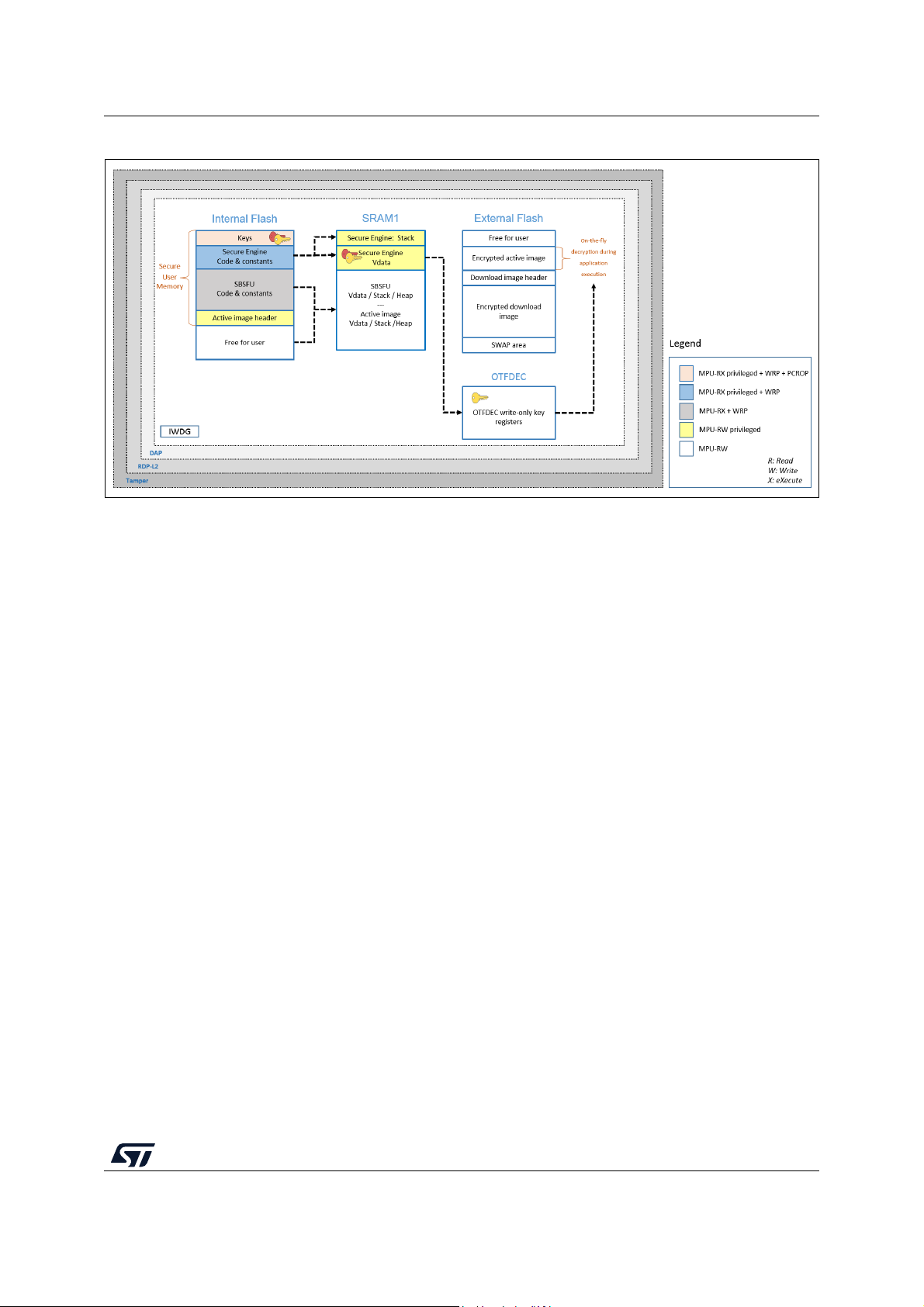
UM2262 STM32H7 Series specificities
Figure 60. STM32H7B3: MPU isolation + secure user memory, with external Flash
During the installation process, active slot firmware remains encrypted to ensure
confidentiality. On-the-fly decryption is performed by OTFDEC peripheral during the
execution of the user application from the external Flash memory.
A specific cryptographic scheme (SECBOOT_ECCDSA_WITH_AES128_CTR_SHA256) is
provided to illustrate the cryptographic operations required for this configuration: This
cryptographic scheme uses AES-CTR encryption and asymmetric (ECDSA) cryptography.
To offer the same level of security as other STM32 microcontrollers, the header of the active
slot must not be accessible during user application execution. For this reason, the header of
the active slot is stored in the internal Flash to be protected through the secure user
memory.
To illustrate this capability, an application called 2 images ExtFlash is provided for the
STM32H7B3I-DK board in the X-CUBE-SBSFU Expansion Package. Figure
61 shows the
typical memory mapping for such a configuration.
UM2262 Rev 8 97/104
102
Page 98

STM32H7 Series specificities UM2262
Figure 61. Memory mapping for STM32H7B3 devices with external Flash
98/104 UM2262 Rev 8
Page 99

UM2262 Validation of the new firmware image
Appendix J Validation of the new firmware image
Before the completion of the firmware update process, the user may need to control the
validity of the new image via the execution of the self-test. To enable this mechanism, the
switch ENABLE_IMAGE_STATE_HANDLING must be activated.
This feature can be activated only on a dual-slot configuration example with Secure Engine
runtime services available and the swap installation process selected. This is not the case
for series with secure memory.
A parameter called FwImageState is stored in the header of the image to indicate the state
of the firmware image and is updated according to the process of installation and validation
of the new image.
At the first user application start-up, if the execution is correct (for example after self-tests
execution) the user application must call a running service SE_APP_Validate(slot_id) to
validate the firmware image. If not done a rollback on the previous firmware image will be
performed by SBSFU at the next reset.
The flow is described in Figure 62.
Figure 62. Image state handling
In a multiple image configuration, the slot identification parameter can be either 1,2,3 or 255.
The value 255 indicates that all new firmware images will be validated through a single
UM2262 Rev 8 99/104
102
Page 100

Validation of the new firmware image UM2262
request. The objective is to ensure the firmware compatibility between all new images in
case of interruption during the validation phase.
100/104 UM2262 Rev 8
 Loading...