

Page 1

UM2277
User manual
Getting started with MotionTL tilt measurement library in X-CUBE-MEMS1
expansion for STM32Cube
Introduction
The MotionTL middleware library is part of the X-CUBE-MEMS1 software and runs on STM32. It provides real-time information
about the tilt angles of the user device, i.e. cell phone. The library is also able to perform accelerometer 6-position calibration.
This library is intended to work with ST MEMS only.
The algorithm is provided in static library format and is designed to be used on STM32 microcontrollers based on the ARM
Cortex®-M0+, ARM® Cortex®-M3, ARM® Cortex®-M4 or ARM® Cortex®-M7 architecture.
It is built on top of STM32Cube software technology to ease portability across different STM32 microcontrollers.
The software comes with a sample implementation running on an X-NUCLEO-IKS01A2, X-NUCLEO-IKS01A3 or X-NUCLEO-
IKS02A1 expansion board on a NUCLEO-F401RE, NUCLEO-L476RG, NUCLEO-L152RE or NUCLEO-L073RZ development
board.
®
UM2277 - Rev 8 - April 2021
For further information contact your local STMicroelectronics sales office.
www.st.com
Page 2
1 Acronyms and abbreviations
Table 1. List of acronyms
Acronym Description
API Application programming interface
BSP Board support package
GUI Graphical user interface
HAL Hardware abstraction layer
IDE Integrated development environment
UM2277
Acronyms and abbreviations
UM2277 - Rev 8
page 2/20
Page 3

UM2277
MotionTL middleware library in X-CUBE-MEMS1 software expansion for STM32Cube
2 MotionTL middleware library in X-CUBE-MEMS1 software expansion
for STM32Cube
2.1 MotionTL overview
The MotionTL library expands the functionality of the X-CUBE-MEMS1 software.
The library acquires data from the accelerometer and provides real-time tilt information with multi-mode support
for 3-axis accelerometer. This library is suitable for static inclinometer where system acceleration is negligible,
such as in industrial applications, leveling, satellite antennas, solar panels, and automotive.
The library is also able to perform accelerometer 6-position calibration.
The library is designed for ST MEMS only. Functionality and performance when using other MEMS sensors are
not analyzed and can be significantly different from what described in the document.
A sample implementation is available for X-NUCLEO-IKS01A2, X-NUCLEO-IKS01A3 and X-NUCLEO-IKS02A1
expansion boards, mounted on a NUCLEO-F401RE, NUCLEO-L476RG, NUCLEO-L152RE or NUCLEO-L073RZ
development board.
2.2 MotionTL library
Technical information fully describing the functions and parameters of the MotionTL APIs can be found in the
MotionTL_Package.chm compiled HTML file located in the Documentation folder.
2.2.1 MotionTL library description
The MotionTL pedometer library manages the data acquired from the accelerometer; it features:
• calculation of pitch, roll and gravity inclination angles (Pitch-Roll-Gravity-Inclination mode)
• calculation of theta, psi and phi tilt angles (Theta-Psi-Phi mode)
• accelerometer 6-position calibration
• measurement based on the accelerometer data only
• configure knobs to mitigate vibration noise
• output: tilt angles, validity flag, expected error
• recommended sensor data sampling frequency of 100 Hz and support for all Full Scale ranges
• resources requirements:
– Cortex-M0+: 4.1 kB of code and 0.2 kB of data memory
– Cortex-M3: 3.6 kB of code and 0.2 kB of data memory
– Cortex-M4: 3.3 kB of code and 0.2 kB of data memory
– Cortex-M7: 3.3 kB of code and 0.2 kB of data memory
•
available for ARM® Cortex®-M0+, ARM® Cortex®-M3 and ARM® Cortex®-M4 and ARM® Cortex®-M7
architectures
2.2.2 MotionTL APIs
The MotionTL library APIs are:
• void MotionTL_Initialize(MTL_mcu_type_t mcu_type, const char *acc_orientation)
– performs MotionTL library initialization and setup of the internal mechanism
– the CRC module in STM32 microcontroller (in RCC peripheral clock enable register) has to be enabled
before using the library
• mcu_type is the type of MCU:
– MFX_CM0P_MCU_STM32 is a standard STM32 MCU
– MFX_CM0P_MCU_BLUE_NRG1 is BlueNRG-1
– MFX_CM0P_MCU_BLUE_NRG2 is BlueNRG-2
– MFX_CM0P_MCU_BLUE_NRG_LP is BlueNRG-LP
• *acc_orientation is the reference system of the accelerometer raw data
UM2277 - Rev 8
page 3/20
Page 4

Note: This function must be called before using the tilt library.
• void MotionTL_SetKnobs(MTL_knobs_t *knobs)
– sets the knobs
– the parameters for the structure type MTL_knobs_t are:
◦ fullscale is the full scale of accelerometer (in g). It is recommended to set full scale >1g for
the sensor. A lower full scale can be selected if the tilt variation is limited and higher resolution is
required for the application.
◦ k is the filtering coefficient. The range of k is [0.1 to ODR]. The lower value of k increases the
filtering and removes the noise. For systems with high vibration, it is recommended to reduce the
value of k.
◦ orn[3] is the accelerometer data orientation string of three characters indicating the direction
of each positive orientation of the reference frame used for the accelerometer data output, in the
sequence x, y, z. Valid values are: n (north) or s (south), w (west) or e (east), u (up) or d (down)
(see Figure 1). The orn is defined to bring the sensor into the X-NUCLEO-IKS01A3 frame.
◦ mode is the operational mode where:
• MODE_PITCH_ROLL_GRAVITY_INCLINATION enables angle representation in Euler
angles (Roll, Pitch and Phi) form
• MODE_THETA_PSI_PHI enables angle computation of theta, psi and phi angle which
measure the angle individually on each axis
Note: The API can be called after MotionTL_Initialize() but before MotionTL_Update()
UM2277
MotionTL library
• void MotionTL_GetKnobs(MTL_knobs_t *knobs)
– gets the knobs setting
– for the parameters for the structure type MTL_knobs_t refer to the MotionTL_SetKnobs() function
• void MotionTL_Update(MTL_input_t *data_in, uint64_t timestamp_ms, MTL_output_t
*data_out)
– executes the tilt algorithm
– *data_in parameter is a pointer to a structure with input data
– timestamp_ms is the time stamp in milliseconds
– *data_out parameter is a pointer to a structure with output data
– the parameters for the structure type MTL_input_t are:
◦ acc_x is the accelerometer sensor value in X axis in g
◦ acc_y is the accelerometer sensor value in Y axis in g
◦ acc_z is the accelerometer sensor value in Z axis in g
– the parameters for the structure type MTL_output_t are:
◦ theta_3x in Theta-Psi-Phi mode – the angle between X axis and the horizontal plane. The
range of angle is [-90, 90] degrees.
◦ psi_3x in Theta-Psi-Phi mode – the angle between Y axis and the horizontal plane. The range of
angle is [-90, 90] degrees.
◦ phi_3xin both modes – the angle between X-Y planes and the horizontal plane. The range of
angle is [0, 90] degrees.
◦ roll_3x in Pitch-Roll-Gravity-Inclination – the roll angle. The range of angle is [-180, 180]
degrees.
◦ pitch_3x in Pitch-Roll mode – the pitch angle. The range of angle is [-90, 90] degrees.
◦ err_deg in both modes – the predicted angle error. The range of error in angle is [0, 90]
degrees. The output can be used to accept/reject the tilt angle.
◦ valid in both modes, this flag is used to show if output is valid or not. If accelerometer reading is
showing high vibration or saturation at full scale, library will output ‘0’ in the valid field.
Note: In Pitch-Roll-Gravity-Inclination mode, the psi_3x value represents gravity_inclination_3x value.
UM2277 - Rev 8
page 4/20
Page 5

UM2277
MotionTL library
• uint8_t MotionTL_GetLibVersion(char *version)
– retrieves the library version
– *version is a pointer to an array of 35 characters
– returns the number of characters in the version string
• void MotionTL_CalibratePosition(float cal_data[][3], uint32_t num_records,
MTL_cal_position_t cal_position)
– calibrates accelerometer in a specific position
– calData parameter is a 2D array with accelerometer data for calibration (3 axes per record)
– nRecords parameter is the number of records
– calPosition parameter is an enumeration of the desired position
– the values for the enumeration type MTL_CalPosition_t are:
◦ X_UP
◦ X_DOWN
◦ Y_UP
◦ Y_DOWN
◦ Z_UP
◦ Z_DOWN
• MTL_CalResult_tMotionTL_GetCalValues(MTL_AccCal_t *accCal)
• – gets the calculated calibration values from the library to be used in the application
– the return value is an enumeration of the calibration result
– the values for the enumeration type MTL_CalResult_t are:
◦ CAL_PASS: Calibration passed
◦ CAL_NONE: Calibration not finished or not performed at all
◦ CAL_FAIL: Calibration failed
– accCal parameter is a pointer to a structure with calibration parameters
– the parameters for the structure type MTL_AccCal_t are:
◦ offset parameter is an array with calculated offset for all 3 axes
◦ gain parameter is an array with calculated gain for all 3 axes
• MTL_CalResult_t MotionTL_SetCalValues(MTL_AccCal_t *accCal)
– validates and sets the calibration values passed in the parameter
– the return value is an enumeration of the calibration result
– for the values for the enumeration type MTL_CalResult_t, see MotionTL_GetCalValues()
function
• void MotionTL_SetOrientation_Acc(const char *acc_orientation)
– this function is used to set the accelerometer data orientation
– configuration is usually performed immediately after the MotionTL_Initialize () function call
– *acc_orientation parameter is a pointer to a string of three characters indicating the direction of
each of the positive orientations of the reference frame used for accelerometer data output, in the
sequence x, y, z. Valid values are: n (north) or s (south), w (west) or e (east), u (up) or d (down).
As shown in the figure below, the X-NUCLEO-IKS01A2 accelerometer sensor has an NWU (x-North,
y-West, z-Up), so the string is: “nwu”.
UM2277 - Rev 8
page 5/20
Page 6
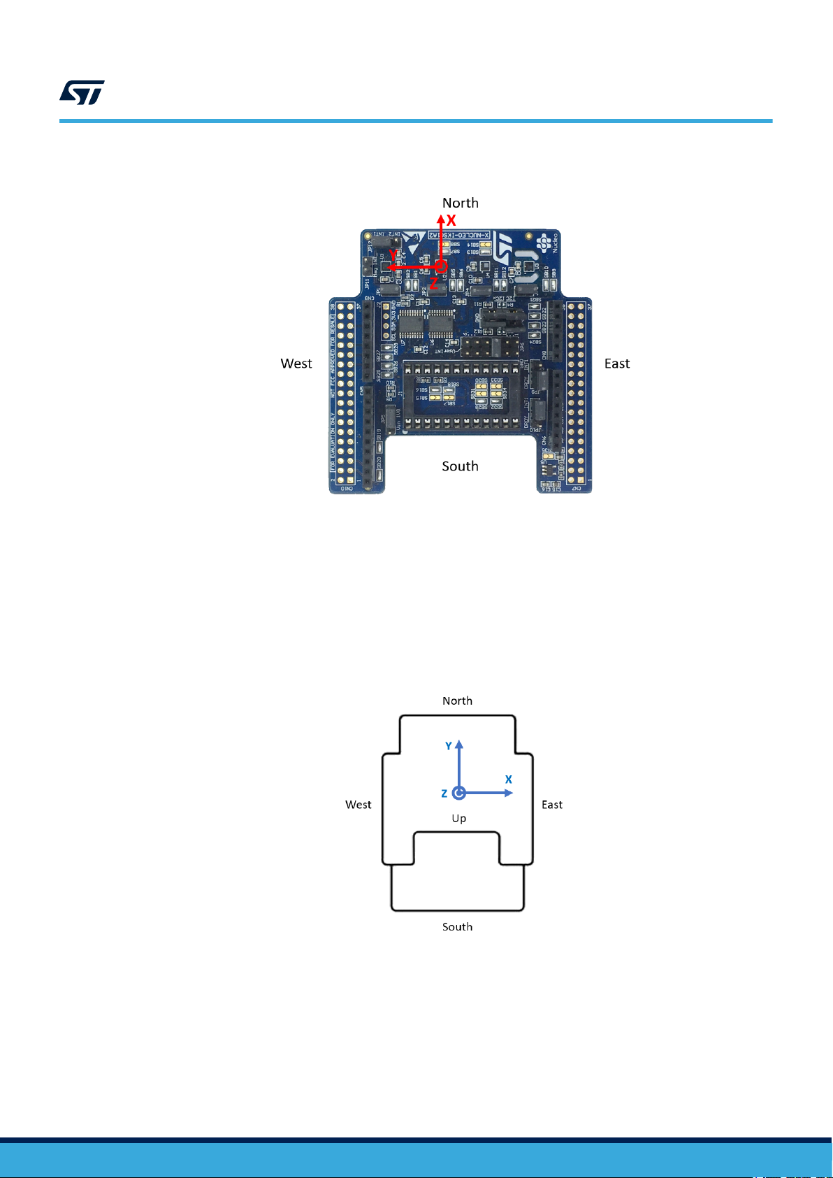
Figure 1. Example of sensor orientations
UM2277
MotionTL library
2.2.3 Orientation
The MotionTL library works with ENU orientation system, which means device X axis going to East, Y axis going
to North, Z axis going Up.
Any sensor orientation is internally transformed into device ENU orientation system. For this reason the sensor
orientation must be defined using MotionTL_SetOrientation_Acc() function. All the outputs (angels) are
then calculated relative to the ENU orientation system.
Figure 2. Device ENU orientation system
UM2277 - Rev 8
The MotionTL library has different types of outputs angles as detailed in the following tables.
page 6/20
Page 7

MotionTL library
Table 2. Pitch, Roll and Gravity Inclination output angles
Value Pitch Roll Gravity Inclination
Formula arctan2 (-Y/Z) arcsin (X) arccos (Z)
Range -180°, +180° -90°, +90° 0, 180°
Description
Sign
Angle between Y axis and horizontal
plane.
Top edge of the device going towards
ground generates positive pitch.
Angle between X axis and horizontal
plane.
Left edge of the device going towards
ground generates positive roll.
Angle between gravity vector
and Z axis.
Always positive.
Table 3. Theta, Psi and Phi output angles
Value Theta Psi Phi
Formula
Range -90°, +90° -90°, +90° -90°, +90°
Description
Sign
arctan (X/sqrt(Y2+Z2)) arctan (Y/sqrt(X2+Z2)) arctan (sqrt(X2+Y2)/Z)
Angle between X axis and
horizontal plane.
Left edge of the device going
towards ground generates positive
theta angle.
Angle between Y axis and
horizontal plane.
Bottom edge of the device going
towards ground generates positive
Psi angle.
Angle between Z axis and gravity
vector.
Positive if Z axis facing up, Negative
if Z axis facing down.
UM2277
Note: Calculation using tangent functions produces constant tilt sensitivity over measurement range.
UM2277 - Rev 8
page 7/20
Page 8

2.2.4 API flow chart
Wait Expiring Timer
Data Read Interrupt
Update
Read Accelerometer Data
Start
Initialize
Get Angles
GetLibVersion
Calculate calib. values in
the desired position
Collect calibration data
Store calibration values
If calibration
command received
UM2277
MotionTL library
Figure 3. MotionTL API logic sequence (main program)
Figure 4. MotionTL API logic sequence (calibration)
UM2277 - Rev 8
page 8/20
Page 9

2.2.5 Demo code
The following demonstration code reads data from the accelerometer sensor and gets the tilt angles.
[…]
#define VERSION_STR_LENG 35
[…]
/*** Initialization ***/
char lib_version[VERSION_STR_LENG];
char acc_orientation[3];
acc_orientation[0] = 'n';
acc_orientation[1] = 'w';
acc_orientation[2] = 'u';
/* Tilt API initialization function */
/* Note: Use MCU type according to target HW – in this example we use standard STM32 MCU */
MotionTL_Initialize(MTL_MCU_STM32, acc_orientation);
/* OPTIONAL */
/* Get library version */
lib_version_len = MotionTL_GetLibVersion(lib_version);
[…]
UM2277
MotionTL library
/*** Using tilt algorithm ***/
Timer_OR_DataRate_Interrupt_Handler()
{
MTL_input_t data_in;
MTL_output_t data_out;
uint64_t timestamp_ms;
/* Set the angle computation mode */
MTL_knobs_t knobs;
MotionTL_GetKnobs(&knobs);
knobs.mode = MODE_THETA_PSI_PHI;
MotionTL_SetKnobs(&knobs);
/* Get acceleration X/Y/Z in g */
MEMS_Read_AccValue(&data_in.acc_x, &data_in.acc_y, &data_in.acc_z);
/* Get timestamp in ms */
timestamp_ms = get_time_ms();
/* Run tilt sensing algorithm */
MotionTL_Update(&data_in, timestamp_ms, &data_out);
}
2.2.6 Algorithm performance
Table 4. Cortex -M4 and Cortex-M3: elapsed time (µs) algorithm
Cortex-M4 STM32F401RE at 84 MHz Cortex-M3 STM32L152RE at 32 MHz
STM32CubeIDE
1.2.0
Min Avg Max Min Avg Max Min Avg Max Min Avg Max Min Avg Max Min Avg Max
80 159 163 104 104 162 104 300 303 514 571 584 373 375 575 375 967 974
IAR EWARM
8.32.3
Keil µVision 5.27
STM32CubeIDE
1.2.0
IAR EWARM
8.32.3
Keil µVision 5.27
UM2277 - Rev 8
page 9/20
Page 10

Table 5. Cortex -M0+ and Cortex-M7: elapsed time (µs) algorithm
Cortex-M0+ STM32L073RZ at 32 MHz Cortex-M7 STM32F767ZI at 96 MHz
STM32CubeIDE
1.2.0
Min Avg Max Min Avg Max Min Avg Max Min Avg Max Min Avg Max Min Avg Max
233 1719 1744 856 860 1727 858 2607 2619 27 28 28 17 18 18 29 30 31
IAR EWARM
8.32.3
2.3 Sample application
The MotionTL middleware can be easily manipulated to build user applications; a sample application is provided
in the Application folder.
It is designed to run on a NUCLEO-F401RE, NUCLEO-L476RG, NUCLEO-L152RE or NUCLEO-L073RZ
development board connected to an X-NUCLEO-IKS01A2, X-NUCLEO-IKS01A3 or X-NUCLEO-IKS02A1
expansion board.
The tilt sensing algorithm only uses data from the accelerometer. It detects and provides real-time information
about the tilt angles of the user device. The library is also able to perform accelerometer 6-position calibration if
required. The data can be displayed through a GUI.
A USB cable connection is required to monitor real-time data. This allows the user to display in real-time
calculated tilt angles, accelerometer data, time stamp and eventually other sensor data using the Unicleo-GUI.
After pressing the Tilt Calibrate button in the Unicleo-GUI, the user is asked to hold the device still in each of the
six positions while the calibration data is collected. Then the calibration parameters (offset and gain for all 3 axes)
are calculated and sent to the Unicleo-GUI.
Keil µVision 5.27
STM32CubeIDE
1.2.0
IAR EWARM
8.32.3
UM2277
Sample application
Keil µVision 5.27
2.4 Unicleo-GUI application
The sample application uses the Windows Unicleo-GUI utility, which can be downloaded from www.st.com.
Step 1. Ensure that the necessary drivers are installed and the STM32 Nucleo board with appropriate
expansion board is connected to the PC.
Step 2. Launch the Unicleo-GUI application to open the main application window.
If an STM32 Nucleo board with supported firmware is connected to the PC, it is automatically detected
and the appropriate COM port is opened.
Figure 5. Unicleo main window
UM2277 - Rev 8
page 10/20
Page 11

Unicleo-GUI application
Step 3. Start and stop data streaming by using the appropriate buttons on the vertical tool bar.
The data coming from the connected sensor can be viewed in the User Messages tab.
Figure 6. User Messages tab
UM2277
UM2277 - Rev 8
page 11/20
Page 12

Unicleo-GUI application
Step 4. Click on the Motion Tilt icon in the vertical tool bar to open the dedicated application window.
Figure 7. Motion Tilt Sensing window 1
UM2277
You can switch between two angle modes. In the first mode the Pitch, Roll and Gravity Inclination
angles are displayed, in the second mode the Theta, Psi and Phi angles are displayed. The meaning of
the angles in the second mode is displayed right below each indicator:
Figure 8. Motion Tilt Sensing window 2
UM2277 - Rev 8
page 12/20
Page 13

UM2277
Unicleo-GUI application
Step 5. Click on the Tilt Calibration icon in the vertical toolbar to open the dedicated application window
Figure 9. Motion Tilt calibration window 1
This window first shows currently used calibration values calculated and stored during the previous
calibration or default values if the calibration has never been performed.
You can start a new calibration by clicking the Start button:
a. put the device in the first calibration position as displayed in the picture that shows up (see
Figure 8. Motion Tilt Sensing window 2)
b. click Next and hold the device still until the picture changes to another calibration position
c. repeat these steps for all 6 calibration positions.
The information about the estimated time necessary for taking all calibration data in the current position
is also displayed. Once the last position is calibrated, the new calibration parameters are calculated
and displayed in the window (see Figure 7. Motion Tilt Sensing window 1).
UM2277 - Rev 8
page 13/20
Page 14

Figure 10. Motion Tilt calibration window 2
UM2277
Unicleo-GUI application
Step 6. Click on the Datalog icon in the vertical tool bar to open the datalog configuration window:
you can select which sensor and activity data to save in files. You can start or stop saving by clicking
on the corresponding button.
You can also load the previously stored data.
Figure 11. Datalog window
UM2277 - Rev 8
page 14/20
Page 15

3 References
All of the following resources are freely available on www.st.com.
1. UM1859: Getting started with the X-CUBE-MEMS1 motion MEMS and environmental sensor software
expansion for STM32Cube
2. UM1724: STM32 Nucleo-64 boards (MB1136)
3. UM2128: Getting started with Unicleo-GUI for motion MEMS and environmental sensor software expansion
for STM32Cube
UM2277
References
UM2277 - Rev 8
page 15/20
Page 16

Revision history
Date Version Changes
22-Sep-2017 1 Initial release.
25-Jan-2018 2
21-Mar-2018 3 Updated Introduction and Section 2.1 MotionTL overview.
23-Oct-2018 4
20-Nov-2018 5
21-Feb-2019 6
25-Mar-2020 7
07-Apr-2021 8
UM2277
Table 6. Document revision history
Added references to NUCLEO-L152RE development board and Section 2.2.5 Algorithm
performance.
Removed references to X-NUCLEO-IKS01A1 throughout document.
Updated Figure 1. Example of sensor orientations and Section 2.2.5 Demo code.
Added Section 2.2.3 Orientation.
Added Table 5. Cortex -M0+: elapsed time (µs) algorithm.
Added references to ARM
Updated Table 4. Cortex -M4 and Cortex-M3: elapsed time (µs) algorithm and Table 5. Cortex -M0+:
elapsed time (µs) algorithm.
Added X-NUCLEO-IKS01A3 expansion board compatibility information.
Updated Introduction, Section 1.1 MotionTL library description and Section 2.2.6 Algorithm
performance.
Added ARM Cortex-M7 architecture compatibility information.
Updated Introduction, Section 2.1 MotionTL overview, Section 2.2.1 MotionTL library description,
Section 2.2.2 MotionTL APIs, Section 2.2.4 API flow chart, Section 2.2.5 Demo code and
Section 2.3 Sample application.
Added X-NUCLEO-IKS02A1 expansion board compatibility information.
®
Cortex®-M0+ and NUCLEO-L073RZ development board.
UM2277 - Rev 8
page 16/20
Page 17

UM2277
Contents
Contents
1 Acronyms and abbreviations ......................................................2
2 MotionTL middleware library in X-CUBE-MEMS1 software expansion for STM32Cube
....................................................................................3
2.1 MotionTL overview .............................................................3
2.2 MotionTL library................................................................3
2.2.1 MotionTL library description ................................................3
2.2.2 MotionTL APIs ..........................................................3
2.2.3 Orientation .............................................................6
2.2.4 API flow chart ...........................................................8
2.2.5 Demo code .............................................................9
2.2.6 Algorithm performance ....................................................9
2.3 Sample application ............................................................10
2.4 Unicleo-GUI application ........................................................10
3 References .......................................................................15
Revision history .......................................................................16
UM2277 - Rev 8
page 17/20
Page 18

UM2277
List of tables
List of tables
Table 1. List of acronyms ....................................................................2
Table 2. Pitch, Roll and Gravity Inclination output angles ...............................................7
Table 3. Theta, Psi and Phi output angles .........................................................7
Table 4. Cortex -M4 and Cortex-M3: elapsed time (µs) algorithm ......................................... 9
Table 5. Cortex -M0+ and Cortex-M7: elapsed time (µs) algorithm ....................................... 10
Table 6. Document revision history ............................................................. 16
UM2277 - Rev 8
page 18/20
Page 19

UM2277
List of figures
List of figures
Figure 1. Example of sensor orientations .........................................................6
Figure 2. Device ENU orientation system.........................................................6
Figure 3. MotionTL API logic sequence (main program)............................................... 8
Figure 4. MotionTL API logic sequence (calibration) .................................................8
Figure 5. Unicleo main window............................................................... 10
Figure 6. User Messages tab ................................................................ 11
Figure 7. Motion Tilt Sensing window 1 ......................................................... 12
Figure 8. Motion Tilt Sensing window 2 ......................................................... 12
Figure 9. Motion Tilt calibration window 1........................................................ 13
Figure 10. Motion Tilt calibration window 2........................................................ 14
Figure 11. Datalog window .................................................................. 14
UM2277 - Rev 8
page 19/20
Page 20

UM2277
IMPORTANT NOTICE – PLEASE READ CAREFULLY
STMicroelectronics NV and its subsidiaries (“ST”) reserve the right to make changes, corrections, enhancements, modifications, and improvements to ST
products and/or to this document at any time without notice. Purchasers should obtain the latest relevant information on ST products before placing orders. ST
products are sold pursuant to ST’s terms and conditions of sale in place at the time of order acknowledgement.
Purchasers are solely responsible for the choice, selection, and use of ST products and ST assumes no liability for application assistance or the design of
Purchasers’ products.
No license, express or implied, to any intellectual property right is granted by ST herein.
Resale of ST products with provisions different from the information set forth herein shall void any warranty granted by ST for such product.
ST and the ST logo are trademarks of ST. For additional information about ST trademarks, please refer to www.st.com/trademarks. All other product or service
names are the property of their respective owners.
Information in this document supersedes and replaces information previously supplied in any prior versions of this document.
© 2021 STMicroelectronics – All rights reserved
UM2277 - Rev 8
page 20/20
 Loading...