

Page 1

UM2178
User manual
Getting started with X-CUBE-AWS STM32Cube Expansion Package
for Amazon Web Services® IoT
Introduction
This user manual describes the content of the X-CUBE-AWS STM32Cube Expansion Package for AWS (Amazon Web
Services®) IoT (Internet of Things) Core.
The X-CUBE-AWS STM32Cube Expansion Package for AWS IoT Core
•
provides a qualified port of FreeRTOS™ to the supported boards (refer to the User Guide and FreeRTOS Qualification
Guide sections on the AWS website at docs.aws.amazon.com/freertos for details)
• offloads – wherever available – the security-critical operations to the on-board STSAFE-A110 Secure Element during
– the MCU boot process
–
the TLS device authentication towards the AWS IoT Core™ server
– the verification of the over-the-air (OTA) update firmware image integrity and authenticity.
It leverages the Secure Element provisioned certificate with the AWS IoT Core Multi-Account Registration feature
™
Refer to Section 1 General information for a presentation of AWS IoT Core™ and FreeRTOS™.
This user manual focuses on X-CUBE-AWS v2.x, which follows the v1.x versions, connecting to the same AWS IoT Core
services and therefore compatible with the same cloud services.
X-CUBE-AWS v2.x is a different solution from X-CUBE-AWS v1.x. It is based on the complete FreeRTOS™ software
distribution, which coexists with the STM32Cube environment, and not on the AWS IoT Device SDK for Embedded C single
middleware library anymore.
Both the aws_demos and aws_tests FreeRTOS™ reference applications are provided:
• aws_demos is configured to illustrate the usage of the FreeRTOS™OTA Update Manager service.
• aws_tests is the test application of the AWS Qualification Program for FreeRTOS™. It is provided as a possible comparison
point for the users who plan to get their product go through the qualification process. Its usage is beyond the scope of the
present document.
X-CUBE-AWS version v2.0.0 is available for the B-L4S5I-IOT01A Discovery kit.
™
UM2178 - Rev 4 - September 2020
For further information contact your local STMicroelectronics sales office.
www.st.com
Page 2

1 General information
The X-CUBE-AWS Expansion Package is dedicated to FreeRTOS™ projects running on STM32 32-bit
microcontrollers based on the Arm® Cortex®-M processor. The descriptions in the current revision of the user
manual are based on X-CUBE-AWS v2.0.0.
Note: Arm is a registered trademark of Arm Limited (or its subsidiaries) in the US and/or elsewhere.
UM2178
General information
1.1
Note: © 2020, Amazon Web Services, Inc. or its affiliates. All rights reserved.
1.2
Note: © 2020, Amazon Web Services, Inc. or its affiliates. All rights reserved.
1.3
What is AWS IoT Core™?
As described on the AWS website at docs.aws.amazon.com/iot,
AWS IoT Core is a managed cloud service that lets connected devices securely interact with cloud
applications and other devices. AWS IoT Core also makes it easy to use AWS and Amazon services like
AWS Lambda, Amazon Kinesis, Amazon S3, Amazon SageMaker, Amazon DynamoDB, Amazon
CloudWatch, AWS CloudTrail, Amazon QuickSight, and Alexa Voice Service to build IoT applications that
gather, process, analyze and act on data generated by connected devices.
What is FreeRTOS™?
As described on the AWS website at docs.aws.amazon.com/freertos,
FreeRTOS is an open source, real-time operating system for microcontrollers that makes small, low-power
edge devices easy to program, deploy, secure, connect, and manage. FreeRTOS includes a kernel and a
growing set of software libraries suitable for use across industry sectors and applications. This includes
securely connecting small, low-power devices to AWS cloud services like AWS IoT Core.
What is STM32Cube?
STM32Cube is an STMicroelectronics original initiative to significantly improve designer's productivity by reducing
development effort, time and cost. STM32Cube covers the whole STM32 portfolio.
UM2178 - Rev 4
page 2/31
Page 3

UM2178
How does X-CUBE-AWS complement STM32Cube?
STM32Cube includes:
• A set of user-friendly software development tools to cover project development from the conception to the
realization, among which are:
– STM32CubeMX, a graphical software configuration tool that allows the automatic generation of C
initialization code using graphical wizards
– STM32CubeIDE, an all-in-one development tool with peripheral configuration, code generation, code
compilation, and debug features
– STM32CubeProgrammer (STM32CubeProg), a programming tool available in graphical and command-
line versions
– STM32CubeMonitor (STM32CubeMonitor, STM32CubeMonPwr, STM32CubeMonRF,
STM32CubeMonUCPD) powerful monitoring tools to fine-tune the behavior and performance of STM32
applications in real-time
• STM32Cube MCU and MPU Packages, comprehensive embedded-software platforms specific to each
microcontroller and microprocessor series (such as STM32CubeL4 for the STM32L4 Series), which include:
– STM32Cube hardware abstraction layer (HAL), ensuring maximized portability across the STM32
portfolio
– STM32Cube low-layer APIs, ensuring the best performance and footprints with a high degree of user
control over the HW
– A consistent set of middleware components such as FAT file system, RTOS, USB Host and Device,
TCP/IP, Touch library, and Graphics
– All embedded software utilities with full sets of peripheral and applicative examples
• STM32Cube Expansion Packages, which contain embedded software components that complement the
functionalities of the STM32Cube MCU and MPU Packages with:
– Middleware extensions and applicative layers
– Examples running on some specific STMicroelectronics development boards
1.4
How does X-CUBE-AWS complement STM32Cube?
X-CUBE-AWS extends STM32CubeL4 by providing a qualified port of FreeRTOS™ to the B-L4S5I-IOT01A board,
with a pre-integrated secure bootloader derived from the X-CUBE-SBSFU Expansion Package and adapted to
offload the most sensitive cryptographic operations to the embedded STSAFE-A110 Secure Element.
By exception to the STM32Cube physical architecture, the whole FreeRTOS™ source tree, with its own
dependencies and third party libraries, is installed as a whole, as a third-party middleware in the STM32Cube
source tree.
UM2178 - Rev 4
page 3/31
Page 4

UM2178
Amazon Web Services® IoT Core
2
Amazon Web Services® IoT Core
Figure 1. Amazon Web Services® IoT Core ecosystem
2.1 Online documentation
The user application presented in this document relies on FreeRTOS™ and AWS (mostly the AWS IoT Core
services).
General documentation, user guide, developer guide, porting guide, OTA Firwmare Update guide, and others are
available on the AWS website.
Most of the documentation of the OTA demo application on the FreeRTOS™ web site (documentation of the OTA
library, Basic OTA Demo (with Code Signing) page) is also relevant – with differences in the Configuring the
Demo Project section, due to the usage of the multi-account device registration method on the B-L4S5I-IOT01A
board.
While Section 5.2.2 User application configuration provides a quick guide on how to get and authorize AWS
credentials, the information presented in this document cannot substitute for the Amazon™ information, which is
the reference.
2.2 Account configuration, device registration, device provisioning
The included B-L4S5I-IOT01A user applications use the Multi-Account Registration feature of the AWS IoT Core
service.
A unique immutable X.509 device certificate is stored in the physical device at production time, in the STSAFE-
A110 Secure Element. This certificate must be extracted from the physical device to be registered at AWS when
the logical device (called thing in AWS terminology) is created by the user.
The instructions of the present section must be followed through before proceeding to the operations in
Section 5.2.2 User application configuration and launch.
™
™
UM2178 - Rev 4
page 4/31
Page 5

Step 1. Extract the device certificate.
This is done in two steps (refer to Section 4.3 Programming a firmware image to the STM32 board
and Section 4.2 Virtual terminal setup)
a. Program and run the image Projects/<board_name>/Applications/BootLoader_STSAF
E/STSAFE_Provisioning/Binary/Provisioning.bin so that the STSAFE-A110 Secure
Element and the MCU bootloader are paired and may communicate securely with each other.
b. Build, program and run the image Projects\<board_name>\Applications\Cloud\aws_d
emos\<toolchain>\PostBuild\SBSFU_<board_name>_aws_demos.bin.(no need to
configure in the source code at this stage). Copy the PEM format certificate displayed on the
virtual terminal to a text file. It is referred to it as “my_extracted_cert.pem” in the next steps.
The .bin file above is automatically produced by the post-build stage of the aws_demos
application build project. Refer to Section 5.1.3 Building the whole firmware image for
information on the SBSFU build system.
Important: The .pem file must exactly contain the text block starting with (and including) -----BEGIN
CERTIFICATE----- and ending with -----END CERTIFICATE-----.
= [SBOOT] System Security Check successfully passed. Starting...
= [FWIMG] Slot #0 @: 8105000 / Slot #1 @: 8036000 / Swap @: 81d5000
======================================================================
= (C) COPYRIGHT 2017 STMicroelectronics =
= =
= Secure Boot and Secure Firmware Update =
======================================================================
= [SBOOT] STATE: WARNING: SECURE ENGINE INITIALIZATION WITH FACTORY DEFAULT VALUES!
= [SBOOT] STATE: CHECK STATUS ON RESET
INFO: A Reboot has been triggered by a Software reset!
Consecutive Boot on error counter = 0
INFO: Last execution detected error was:No error. Success.
= [SBOOT] STATE: CHECK NEW FIRMWARE TO DOWNLOAD
= [SBOOT] STATE: CHECK KMS BLOB TO INSTALL
= [SBOOT] STATE: CHECK USER FW STATUS
= [SBOOT] LOADING CERTS FROM SECURE ENGINEOK
= [SBOOT] Verifying the Certificate chain... OK
= [SBOOT] Verify Header Signature... OK A valid FW is installed in the active slot
- version: 1
= [SBOOT] STATE: VERIFY USER FW SIGNATURE
= [SBOOT] CHECKING IMAGE STATE = SFU_IMG_CheckImageState Image State = 1
= [SBOOT] IMAGE STATE OK = [SBOOT] STATE: EXECUTE USER FIRMWARE0 524 [Tmr Svc] WiFi
module initialized.
1 532 [Tmr Svc] Device Certificate (DER), size = 402
2 537 [Tmr Svc] Device Certificate (PEM), size = 600
-----BEGIN CERTIFICATE----MIIBjjCCATSgAwIBAgILAglQvgEhzCJbATkwCgYIKoZIzj0EAwIwTzELMAkGA1UE
BhMCTkwxHjAcBgNVBAoMFVNUTWljcm9lbGVjdHJvbmljcyBudjEgMB4GA1UEAwwX
U1RNIFNUU0FGRS1BIFBST0QgQ0EgMDEwIBcNMjAwMjI2MDAwMDAwWhgPMjA1MDAy
MjYwMDAwMDBaMEYxCzAJBgNVBAYTAkZSMRswGQYDVQQKDBJTVE1pY3JvZWxlY3Ry
b25pY3MxGjAYBgNVBAMMEVNUU0FGRS1BMTEwIEVWQUwyMFkwEwYHKoZIzj0CAQYI
KoZIzj0DAQcDQgAEv/XwIjVwhq0S9R1fCeQj8QXr6y3AcXMJIFOtV2GpGhxAkseK
QeIe2tMoAkzwwmDdixmFwT/pJuHYvZu6IY6n4TAKBggqhkjOPQQDAgNIADBFAiBq
1p9SL6sAXB1zKsgX9Pr68tKDjKbb2ZZTPcSQ5cU9oAIhAIWMVkv4wIL02v8JXzRN
HSRb1zUmb840Eo6c2rJKPG6a
-----END CERTIFICATE----3 595 [Tmr Svc] WiFi Firmware Version C3.5.2.5.STM.
UM2178
Account configuration, device registration, device provisioning
UM2178 - Rev 4
Step 2. Sign-in to or create an AWS account.
Set the required user, access rights and policies for the multi-account registration mechanism. Note
that the multi-account registration relieves from creating and provisioning the IoT device credentials.
For this specific point, refer to step 5. below. Possible references are:
– The Setting up your AWS account and permissions section of the FreeRTOS™ User Guide on
Amazon™ website
– The Getting started with AWS IoT Core section of the AWS IoT Developer Guide
page 5/31
Page 6

Step 3. Create an IoT thing policy.
This policy is called “my_iot_policy” in the next steps. Users having used AWS IoT Core™ in the past
(for instance with X-CUBE-AWS v1.x) can reuse their thing policy.
Step 4. Install and setup the AWS CLI.
In addition to the default section, set the profile adminuser section in ~/.aws/credentials
with
– region
– aws_access_key_id
– aws_secret_access_key
Users with personal AWS accounts given the required access rights may simply copy the [default]
settings to the [profile adminuser] section.
Step 5. Register the device.
– Register the X.509 certificate copied from the device console:
aws iot register-certificate-without-ca --certificate-pem file://
my_extracted_cert.pem --status ACTIVE
Note the contents of the certificateArn field that is returned by the command, called
“my_device_cert_arn” in the next steps. Its format is:
arn:aws:iot:<my_region>:<my_account_id>:cert/<my_extracted_cert_id>
– Create the thing:
aws iot create-thing --thing-name my_thing_name
– Empower the thing by granting its certificate with the access rights defined in the thing policy:
aws iot attach-policy --policy-name "my_iot_policy" --target
"my_device_cert_arn"
aws iot attach-thing-principal --thing-name my_thing_name --principal
my_device_cert_arn
– Retrieve the address of the IoT Core endpoint:
aws iot describe-endpoint --endpoint-type iot:Data-ATS
It is called “my_endpoint_name” in the next steps in the User application configuration section. Its
format is:
<account-specific_prefix>-ats.iot.<my_region>.amazonaws.com.
UM2178
Account configuration, device registration, device provisioning
UM2178 - Rev 4
page 6/31
Page 7

3 Package description
3.1 Logical software architecture
The top-level architecture of the X-CUBE-AWS Expansion Package is shown in Figure 2.
Figure 2. X-CUBE-AWS software architecture
Custom user application
Secure bootloader
Applications
FreeRTOS™
Demos
Platform abstraction port
Tests
UM2178
Package description
PC
software
Key management services
STSAFE-A
Middleware
Drivers
STM32 Wi-Fi
Hardware components
Development boards
Secure Engine
Libraries such as mbedTLS, tinycbor and others
STSAFE-A110
B-L4S5I-IOT01A
FreeRTOS™
Hardware abstraction layer (HAL)Board support package (BSP)
®
module
IoT SDKFreeRTOS kernel
Utilities
CMSIS
Sensors
The Expansion Package provides a FreeRTOS™ software distribution for STM32Cube. It is composed of:
• FreeRTOS™ standard user applications (aws_demos and aws_tests) and their platform abstraction port to
the B-L4S5I-IOT01A board by means of the STM32L4 Series HAL and ISM43362 eS-WiFi driver.
• FreeRTOS™ and its internal dependencies.
• STM32Cube HAL: this driver layer provides a generic multi-instance simple set of APIs (application
programming interfaces) to interact with upper layers (application, libraries and stacks). It is composed of
generic and extension APIs. It is directly built around a generic architecture and allows the layers that are
built upon, such as the middleware layer, to implement their functionalities without dependencies on the
specific hardware configuration for a given microcontroller unit (MCU). This structure improves the library
code reusability and guarantees an easy portability onto other devices. It includes:
– STM32L4 Series HAL
• Board support package (BSP) layer: the software package must support the peripherals on the STM32
boards apart from the MCU. This software is included in the board support package. This is a limited set of
APIs, which provides a programming interface for certain board-specific peripherals such as the LED and
user button. It includes:
– Low-layer driver for the Inventek ISM43362 eS-WiFi module
– Sensor drivers for the B-L4S5I-IOT01A board (not used by the applications provided)
UM2178 - Rev 4
page 7/31
Page 8

• Secure bootloader, key management and image state management application derived from the X-
CUBE-SBSFU Expansion Package, relying on its companion middleware components and on-board
STSAFE-A110 component.
The software is provided as a .zip archive containing source-code.
The following integrated development environments are supported:
• IAR Systems - IAR Embedded Workbench® (EWARM), version 8.32.3 or higher
• STMicroelectronics - STM32CubeIDE, version 1.3.0 or higher
3.2 Folder structure
3.2.1 STM32Cube view
Figure 3 presents the top folder structure of the X-CUBE-AWS Expansion Package. Figure 4, Figure 5, and
Figure 6 further detail the top folder contents.
UM2178
Folder structure
Figure 3. Top folders
Figure 4. Drivers folder
BSPv1 drivers for the bootloader applications.
BSPv2 drivers for the user applications.
Board component drivers,
for instance, the sensors of B-L475E-IOT01A / B-L4S5I-IOT01A.
UM2178 - Rev 4
page 8/31
Page 9

Figure 5. Middlewares folder
Wrapper to the mbed-crypto library
PKCS#11 implementation of the FreeRTOS™ PAL
Components of the secure bootloader applications
Software interface to the STSAFE-A110 secure element
UM2178
Folder structure
FreeRTOS™ software distribution, with its embedded set of
middleware components, demos and tests applications
Cryptographic and TLS libraries used by the bootloader
applications
UM2178 - Rev 4
page 9/31
Page 10

Figure 6. Projects and Utilities folders
Bootloader and Secure Firmware Update application, relying
on the soldered STSAFE-A110 secure element
UM2178
Folder structure
FreeRTOS™ demo application, set up for the over-the-air
firmware update use case
FreeRTOS™ configuration files
IDE project folders: 2 toolchains support
FreeRTOS™ platform abstractions implementation
UM2178 - Rev 4
page 10/31
Page 11

UM2178
Folder structure
The user applications aws_demos and aws_tests provide an implementation of the following FreeRTOS™ porting
abstractions:
• configPRINT_STRING()
• Wi‑Fi
• TCP/IP
• Secure Sockets
• PKCS#11
• TLS
• MQTT
• HTTPS
• Over-the-air (OTA) updates
The mbedTLS user configuration is also overloaded for OTA and STSAFE-A110.
®
3.2.2
FreeRTOS™ view
If for some reason the user needs to adopt the FreeRTOS™ folder tree (for instance cloned from github), the
recommended setup is to copy STM32CubeExpansion_Cloud_AWS_V2.x.y/* contents into the /vendors/s
t folder and remove /vendors/st/Middlewares/Third_Party/amazon-freertos to avoid source code
duplication.
The IAR Embedded Workbench® projects of the provided user applications can be easily adapted to the folder
structure by changing the AFR_DIR variable in Projects/<board_name>/Applications/Cloud/<applica
tion_name>/EWARM/Project.custom_argvars from $PROJ_DIR$\..\..\..\..\..\..\Middlewares
\Third_Party\amazon-freertos to $PROJ_DIR$\..\..\..\..\..\..\..\...
The STM32CubeIDE projects may be modified in an equivalent way by substituting the paths in the .project
and .cproject files.
UM2178 - Rev 4
page 11/31
Page 12
UM2178
Hardware and software environment setup
4 Hardware and software environment setup
4.1 Install STM32CubeProgrammer
The post-build of the user application requires that STM32CubeProgrammer (STM32CubeProg) is installed in C:
\Program Files\STMicroelectronics\STM32Cube\STM32CubeProgrammer. The version is specified in
the package release notes.
4.2 Virtual terminal setup
A serial terminal is required to:
• Extract the device certificate
• Monitor the application status
The example in this document is illustrated with the use of Tera Term. Any other similar tool can be used instead.
When the board is used for the first time, it must be programmed with connection string data:
• Determine the STM32 ST-LINK Virtual COM port used on the PC for the Discovery board. On a Windows
PC, open the Device Manager.
• Open a serial terminal on the PC and connect it to the above Virtual COM port.
A Tera Term initialization script is provided in the package utility directory (refer to Figure 1); this script sets the
correct parameters. To use it, open Tera Term, select [Setup] and then [Restore setup].
Note: The information provided below can be used to configure the UART terminal as an alternative to using the Tera
Term initialization script.
®
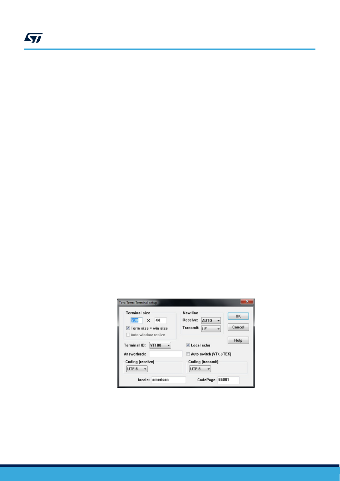
Terminal setup
Terminal setup is illustrated in Figure 7. The screenshot shows the Terminal setup and the New-line
recommended parameters.
The serial terminal New-line transmit configuration must be set to LineFeed (\n or LF) in order to allow copypaste from UNIX® type text files. The selection of the Local echo option makes copy-paste results visible on the
console.
Figure 7. Terminal setup
UM2178 - Rev 4
page 12/31
Page 13
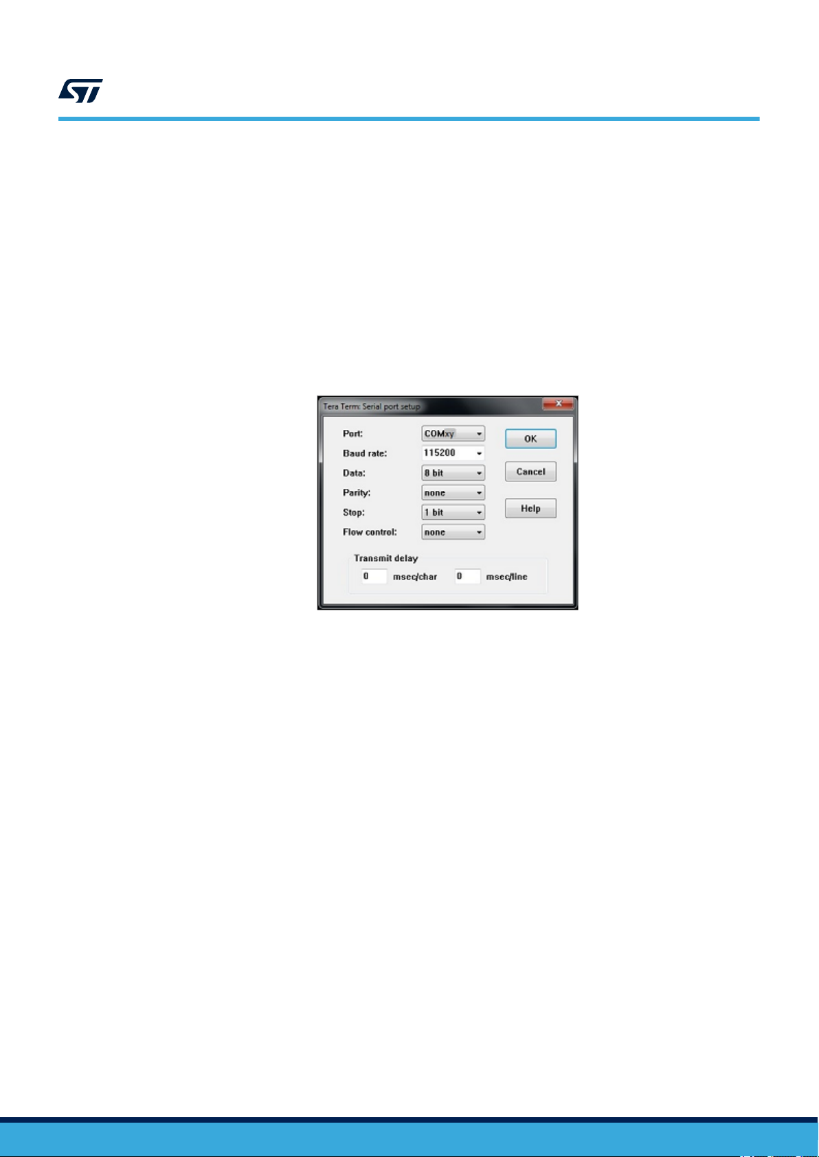
Serial port setup
The serial port must be configured with:
• COM port number
• 115200 baud rate
• 8-bit data
• No parity
• 1 stop bit
• No flow control
Serial port setup is illustrated in Figure 8.
UM2178
Programming a firmware image to the STM32 board
Figure 8. Serial port setup
4.3
Once the UART terminal and the serial port are set up, press the board reset button (black). Follow the indications
on the UART terminal to upload Wi‑Fi® and cloud configuration data. These data remain in the Flash memory and
are reused the next time the board boots.
Programming a firmware image to the STM32 board
Several options are available:
1. Copy (or drag and drop) the .bin file to the USB mass storage mount point created when the STM32 board
is connected to the computer. This is typically DIS_L4IOT, or /media/DIS_L4IOT on Linux®.
2. Program the STM32 board directly by means of one of the supported IDEs, STM32 ST-Link Utility (STSW-
LINK004), or STM32CubeProgrammer (STM32CubeProg).
If the application does not start automatically after the programming, the board must be reset (either with the IDE,
STM32 ST-LINK Utility, STM32CubeProgrammer, or black reset button).
UM2178 - Rev 4
page 13/31
Page 14

UM2178
Applications
5 Applications
5.1 Secure bootloader
5.1.1 Overview
The pre-integrated bootloader allows the update of the user application (initially, one of the standard FreeRTOS
user applications: aws_demos or aws_test), adding new features, and correcting potential issues. This is
performed in a secure way, which prevents any unauthorized update.
The secure bootloader enforces hardware security mechanisms on STM32. It guarantees a unique entry point
after reset, ensures immutable boot code, enforces security check and performs firmware image verification
(authenticity and integrity) before execution.
It takes advantage of hardware protection mechanisms present in STM32 devices:
• RDP-L2: read data protection (disables external access, protects boot options)
• WRP/PCROP: write data protection (protects code and keys from Flash dump, protects trusted code)
• MPU: execution allowed in a chain of trust
• Firewall: protects Flash memory and RAM at runtime (secure enclave for critical operations)
The secure bootloader is a standalone executable. It is delivered in the package both as a pre-built executable
file, and as source files, allowing advanced users to rebuild it with different settings.
Caution: The delivered pre-compiled bootloader does not enforce security, so that the user can still plug a debugger and
debug the application. It must not be used in a production context.
Pre-compiled bootloader settings:
• Dual-image mode
• Enable local loader
• Secure IP turned off
• X.509 ECDSA_SHA256 asymmetric authentication
• No firmware encryption
The dual-image mode enables safe image update, with firmware image backup and rollback capabilities. The
Flash memory is split in two areas named Slot #0 and Slot #1. The Slot #0 area contains the active firmware
(firmware header + firmware). The Slot #1 area can be written a downloaded firmware (firmware header +
encrypted firmware) to be decrypted and installed at next reboot. A specific Flash memory area is used to swap
the content of Slot #0 and Slot #1 during the installation process at boot time. Using those two slots, firmware
update supports a rollback mechanism if an error happens at first execution of a new installed firmware.
The bootloader integration is done in a seamless way, so that the user can keep using the IDE as used to, when
programming the board or debugging.
By contrast to the usual build flow (compile/link/program/debug), specific pre- and post-build phases are added to
the sample projects:
• The post-build phase combines the bootloader with the application, and overwrites the application
executable so that it can be programmed and run as usual.
• The pre-build phase deletes the .elf file to force the link and post-build, even if the user project sources
have not changed. It prevents post-build dependencies issues with STM32CubeIDE.
™
5.1.2 Application boot
The bootloader runs first. It enforces security and checks in Slot #1 if new firmware must be installed.
• If no new firmware must be installed, it starts the already installed application
• If new firmware must be installed, it decrypts if needed, and checks it before installing and running it
Bootloader messages are prefixed with [SBOOT].
In the log below, the bootloader does not find an application to install from Slot #1. Therefore, it checks the
firmware image in Slot #0, and runs it.
UM2178 - Rev 4
page 14/31
Page 15

Secure bootloader
= [SBOOT] System Security Check successfully passed. Starting...
= [FWIMG] Slot #0 @: 8105000 / Slot #1 @: 8036000 / Swap @: 81d5000
======================================================================
= (C) COPYRIGHT 2017 STMicroelectronics =
= =
= Secure Boot and Secure Firmware Update =
======================================================================
= [SBOOT] STATE: WARNING: SECURE ENGINE INITIALIZATION WITH FACTORY DEFAULT VALUES!
= [SBOOT] STATE: CHECK STATUS ON RESET
INFO: A Reboot has been triggered by a Software reset!
Consecutive Boot on error counter = 0
INFO: Last execution detected error was:No error. Success.
= [SBOOT] STATE: CHECK NEW FIRMWARE TO DOWNLOAD
= [SBOOT] STATE: CHECK KMS BLOB TO INSTALL
= [SBOOT] STATE: CHECK USER FW STATUS
= [SBOOT] LOADING CERTS FROM SECURE ENGINEOK
= [SBOOT] Verifying the Certificate chain... OK
= [SBOOT] Verify Header Signature... OK
A valid FW is installed in the active slot - version: 1
= [SBOOT] STATE: VERIFY USER FW SIGNATURE
= [SBOOT] CHECKING IMAGE STATE
= SFU_IMG_CheckImageState Image State = 1
= [SBOOT] IMAGE STATE OK
= [SBOOT] STATE: EXECUTE USER FIRMWARE0 524 [Tmr Svc] WiFi module initialized.
UM2178
5.1.3 Building the whole firmware image
Figure 9 describes the flow for building binary images.
Binary file
produces (1)
Linker
(first step)
produces (1)
Extension:
- .out for
IAR Embedded Workbench
- .elf for STM32CubeIDE
.elf format file
®
Figure 9. Image build flow
Post-build
input
bootloader
input
Modifies to produce a combined image file
(non encrypted user application and bootloader)
Encrypts the initial binary file
and creates the .sfb file for
firmware update
Modifies to produce a combined image file
(non encrypted user application and bootloader)
input
(3)
Post-build
Adds bootloader
to .elf format file
and to binary file
(3)
produces (2)
.sfb file
Legend
st
1
build step
nd
2
build step
Input to the
build flow
Image of 1
build step, then
combined with
nd
2
build step
st
UM2178 - Rev 4
The source files are compiled and linked as usual, which produces a binary file and an .elf format file.
After the link, a post-build script is run.
page 15/31
Page 16

UM2178
Secure bootloader
A file with the .sfb extension is created, which contains the standalone user application, optionally encrypted,
and prefixed with meta data, ready for being downloaded and written at runtime to the firmware update slot.
The script outputs modified .elf and raw binary files, which combine the non-encrypted bootloader and the user
application.
Detail of output files built
The combined image file (raw binary and .elf format) contains both the bootloader and user application. The
user application is placed in the executable slot in a non-encrypted form. The file location depends on the IDE:
• IAR Embedded Workbench
Project/<board_name>/Applications/Cloud/<app_name>/EWARM/<board_name>/Exe/<board
_name>.out
Project/<board_name>/Applications/Cloud/<app_name>/EWARM/<board_name>/<board_nam
e>_AWS.bin
• STM32CubeIDE
Project/<board_name>/Applications/Cloud/<app_name>/STM32CubeIDE/<board_name>/Deb
ug/<board_name>_<app_name>.elf
Project/<board_name>/Applications/Cloud/<app_name>/STM32CubeIDE/<board_name>/Deb
ug/<board_name>_<app_name>.bin
The .sfb file packs the firmware header and firmware image of the user application. This file is the one used
when performing firmware update. Its location depends on the IDE:
• IAR Embedded Workbench
Project/<board_name>/Applications/Cloud/<app_name>/EWARM/PostBuild /<board_name>
_<app_name>.sfb
• STM32CubeIDE
Project/<board_name>/Applications/Cloud/<app_name>/STM32CubeIDE/PostBuild/<board
_name>_<app_name>.sfb
®
®
The post-processing log file is useful to analyze the possible post-build issues. The most common issue is due to
an incorrect path to the STM32CubeProgrammer (STM32CubeProg) tool. The file location depends on the IDE:
• IAR Embedded Workbench
®
Project/<board_name>/Applications/Cloud/<app_name>/EWARM/output.txt
• STM32CubeIDE
Project/<board_name>/Applications/Cloud/<app_name>/STM32CubeIDE/output.txt
Post-processing log file example:
UM2178 - Rev 4
page 16/31
Page 17

UM2178
Secure bootloader
Loading cert: C:\STM32CubeExpansion_Cloud_AWS_V2.x.x\Projects\B-L4S5I-IOT01A\Applications
\BootLoader_STSAFE\2_Images_SECoreBin\EWARM\\\..\\..\\2_Images_SBSFU\\Certs\\sbsfu_fs_crt.der
Loading cert: C:\STM32CubeExpansion_Cloud_AWS_V2.x.x\Projects\B-L4S5I-IOT01A\Applications
\BootLoader_STSAFE\2_Images_SECoreBin\EWARM\\\..\\..\\2_Images_SBSFU\\Certs\\sbsfu_i2_crt.der
adding leaf cert of length 597
adding intermediate cert of length 498
Adding padding: 537
Loading cert: C:\STM32CubeExpansion_Cloud_AWS_V2.x.x\Projects\B-L4S5I-IOT01A\Applications
\BootLoader_STSAFE\2_Images_SECoreBin\EWARM\\\..\\..\\2_Images_SBSFU\\Certs\\sbsfu_fs_crt.der
Loading cert: C:\STM32CubeExpansion_Cloud_AWS_V2.x.x\Projects\B-L4S5I-IOT01A\Applications
\BootLoader_STSAFE\2_Images_SECoreBin\EWARM\\\..\\..\\2_Images_SBSFU\\Certs\\sbsfu_i2_crt.der
adding leaf cert of length 597
adding intermediate cert of length 498
Adding padding: 537
number of segment :1
number of segment :4
0x80001bc
0x801a5d9
0x801bdd4
Merging
SBSFU Base = 0x8000000
Writing header = 0x8105000
APPLI Base = 0x8105800
Writing to C:\STM32CubeExpansion_Cloud_AWS_V2.x.x\Projects\B-L4S5I-IOT01A\Applications\Cloud
\aws_demos\EWARM\\PostBuild\\\\SBSFU_B-L4S5I-IOT01_aws_demos.bin 1351616
"Generating the global elf file (SBSFU and userApp)"
------------------------------------------------------------------ STM32CubeProgrammer v2.4.0
-------------------------------------------------------------------
Warning: The ELF file will be overwritten
ELF file modified successfully
1 file(s) copied.
5.1.4 Rebuilding the bootloader
The bootloader is based on the technology of the X-CUBE-SBSFU Expansion Package. X-CUBE-AWS contains
some sub-modules of X-CUBE-SBSFU:
• Project/<board_name>/Applications/BootLoader_STSAFE/2_Images_SBSFU
• Project/<board_name>/Applications/BootLoader_STSAFE/2_Images_SECoreBin
• Project/<board_name>/Applications/BootLoader_STSAFE/Linker_Common
Refer to the release note in the X-CUBE-AWS Expansion Package for information about the related X-CUBESBSFU version.
The X-CUBE-SBSFU sub-module usage is as follows:
SECorebin contains the Secure Engine Core sources, a protected environment, where all critical data and
operations can be managed in a secure way.
SBSFU implements the Secure Boot and Secure Firmware Update with the support of the Secure Engine Core.
Linker_Common contains the linker files with the definition of the different Slot #0 and Slot #1 areas. The user
application is linked against Slot #0 definition.
The original X-CUBE-SBSFU package is slightly modified to support the FreeRTOS™ user applications (OTA
update image state management, offloading of PKCS#11 services to the STSAFE-A110 component) and to better
integrate with the IDEs. Post-script templates are adapted to help with IDE integration.
Updating the bootloader implies to rebuild, in this order:
1. The Secure Engine library. The project is located in the 2_Images_SE_CoreBin folder.
UM2178 - Rev 4
page 17/31
Page 18

UM2178
Secure bootloader
2. The Secure Boot / Secure Firmware Update executable. The result is called “bootloader” in this document.
Depending on the IDE, it is located in:
– IAR Embedded Workbench
Project/<board_name>/Applications/Bootloader_STSAFE/2_Images_SBSFU/EWARM/<bo
ardname>Exe/Project.out
– STM32CubeIDE
Project/<board_name>/Applications/Bootloader_STSAFE/2_Images_SBSFU/STM32Cube
IDE/<board_name>_2_Images_SBSFU/Debug/SBSFU.elf
Rebuilding the bootloader is required if the bootloader configuration or some linker script files are changed.
The configuration is defined by several files and is based on C preprocessor statements:
• 2_Images_SBSFU/SBSFU/App/app_sfu.h for SBSFU settings
• 2_Images_SECoreBin/Inc/se_crypto_config.h for the cryptography settings
The current bootloader is configured as follows:
• SECBOOT_ECCDSA_WITH_AES128_CBC_SHA256
• SFU_DEBUG_MODE
• SECBOOT_DISABLE_SECURITY_IPS
The secure firmware image is encrypted, but the hardware protections are not enforced. For instance, the JTAG
link is on, so that debugging remains possible. Read the documentation of the X-CUBE-SBSFU Expansion
Package for more information.
®
Programming the user application
From a user perspective, the application gets programmed as usual. Nevertheless, when security is enforced by
the bootloader, it may be necessary to reprogram the Option Bytes to clear some protections and revert to RDPL0 before reprogramming the Flash memory. This can be achieved with the STM32CubeProgrammer
(STM32CubeProg) or STM32 ST-LINK Utility (STSW-LINK004) tools.
Debugging the application
The debugger retrieves the debug information from the user application .elf file (aws_demos or aws_tests in the
present case). It has no access to the bootloader symbols. The debugger places a breakpoint on the main()
function of the user application.
Upon reset:
• In IAR Embedded Workbench®, the debugger starts the application at address 0x0800 0000 so that the
bootloader is executed. For this purpose, IAR Embedded Workbench® is given an extra option:
[Debugger]>[extra options]>[command line option] --drv_vector_table_base=0x0800 0000
• The STM32CubeIDE debugger requires a modification of the .elf file to be able to start at address
0x0800 0000. This modification is performed automatically at the post-build stage of the project (this is
specific to STM32CubeIDE). A tool named bigelftuner.exe changes the entry point of the global .elf
file (combining the bootloader and the application) and sets this entry point to address 0x0800 0000 to start
the bootloader. Still, the debugger places a breakpoint on the main() function of the user application.
5.1.5 Firmware update
The FreeRTOS™ OTA Agent running in the user application enables the AWS IoT Core™ OTA Service to deploy
remotely a new user application version.
UM2178 - Rev 4
OTA Agent and firmware image state
The bootloader implements the management of the firmware image states to be compliant with the OTA Agent
library (refer to the OTA Agent library user guide in FreeRTOS™ documentation).
A downloaded firmware image is received with its status set to “New”. Once the bootloader has installed the
image, the status is updated to “Self Test” and the new firmware image is booted.
Then, it is up to the user application to set the firmware image state to “Accepted” or “Rejected”. If the status is
“Rejected” or if a reset occurs while the image is still in “Self Test” state, a rollback is performed to the previous
firmware image (the one that downloaded the image under validation).
page 18/31
Page 19

The activity flow is summarized in Figure 10.
Figure 10. OTA firmware update activity flow
Firmware Update activity flow
Create the signed
image
Create the MQTT
image stream
Send the FreeRTOS
OTA job
· FW stream URL
· FW signature
· FW destination path
· Signing certificate path
User application SB/SFUAWS OTA Service
OTA Agent:
Subscribe & download
the image stream
OTA Agent / OTA PAL:
- Verify the image signature vs.
the signing certificate
- Store the fimage in the SB/SFU
update slot in Flash (Slot #1)
- Set image state: New
UM2178
Secure bootloader
SW reset
Install the new image
Job status report
Job status record
Demo app /
OTA PAL:
Set image
state: Valid
Job status report
success
Set image state:
version change
Demo app:
SelfTest
failure
Demo app /
OTA PAL:
Invalid
Demo app:
Invalid
Demo app:
Detect no
Legend:
Set image state: SelfTest
launch
HW watchdog
reset (timeout)
Set image state: Invalid
launch
SW reset
Revert the image
installation
launch
Self-test success path
Self-test error path
SB/SFU secure enclave
UM2178 - Rev 4
Step-by-step OTA update
Refer to Section 5.3 Running aws_demos: the MQTT OTA firmware update demonstration.
page 19/31
Page 20

User configuration
5.2 User configuration
5.2.1 Bootloader application configuration
By default, the secure bootloader is configured so that the security protections of the MCU are not enforced, and it
remains possible to attach a debugger.
Refer to Section 5.1.1 Overview and Projects/<board_name>/Applications/Cloud/aws_demos/boot
loader_readme.txt.
5.2.2 User application configuration
Once the registration described in Section 2.2 Account configuration, device registration, device provisioning is
completed, set the credentials in the aws_demos configuration file Middlewares/Third_Party/amazon-fre
ertos/demos/include/aws_clientcredentials.h:
• clientcredentialMQTT_BROKER_ENDPOINT is “my_endpoint_name”
• clientcredentialIOT_THING_NAME is “my_thing_name”
• clientcredentialWIFI_SSID is the WLAN name
• clientcredentialWIFI_PASSWORD is the WLAN password
• clientcredentialWIFI_SECURITY is the WLAN security mode
5.3 Running aws_demos: the MQTT OTA firmware update demonstration
UM2178
1. Re-build the application with the new configuration, program it, and launch it.
– aws_demos successively
◦ connects to the endpoint over TCP/IP and Wi‑Fi
◦ authenticates itself through TLS by means of its pre-provisioned device certificate
◦ enters the MQTT wait loop, pending on the reception of an OTA firmware update job
2. In order to test OTA update, further configuration is required:
a. Create a code signing certificate and profile on the AWS console (once for all) See the Creating a
code-signing certificate for the FreeRTOS Windows simulator page of the FreeRTOS™ user guide for
generating and registering your own ECDSA code signing certificate.
b. Copy the code signing certificate string to the pcClientCertificatePem[] static array in the
OTA PAL (Projects/<board_name>/Applications/Cloud/aws_demos/Src/ports/aws_ota
_pal.c).
Important: This code signing certificate is NOT the device certificate (“my_device_cert_arn”) previously
used for the device registration.
c. Build the application, program, and reset the board.
3. Prepare the application update file and upload it to AWS
a. Increment the application version in aws_application_version.h. This is mandatory to avoid that
the update is rejected by the demo self-test.
b. Build the application, but do NOT program it to the board.
c. Upload the resulting <toolchain_name>/PostBuild/<board_name>_aws_demos.sfb file to a
versioned Amazon S3 bucket listed in the IAM role for OTA update job.
4. Create a FreeRTOS™ OTA update job from the AWS console ([IoT Core]>[Manage]>[Jobs]>[Create]) and
select:
– the thing to update: my_thing_name
– the MQTT protocol for image transfer (HTTP is not supported)
– [Sign a new firmware for me]
– the code signing profile
– the .sfb firmware file, referenced from the S3 bucket where it is uploaded
– any non-empty destination pathname (such as firmware.bin)
– the role for OTA update jobs, which gives access to the S3 buckets and to the IoT Core services
– and finally choose a unique job ID.
®
UM2178 - Rev 4
page 20/31
Page 21

UM2178
Running aws_demos: the MQTT OTA firmware update demonstration
The application then automatically:
• receives and handles the job request
• downloads the .sfb file and stores it into the Slot #0 region of the system Flash memory
• verifies the integrity and the authenticity of the .sfb file against the file signature attached to the job
description, and of the AWS code signing certificate provisioned in the OTA PAL. If the file signature
verification fails (this message is displayed on the device console: [prvPAL_CloseFile] ERROR -
Failed to pass sig-sha256-ecdsa signature verification), the OTA update job is aborted
and reported FAILED to the AWS OTA update service.
• resets the MCU and lets the secure bootloader detect the new .sfb in Slot #0, verify the integrity and the
authenticity of the new user application against the secure bootloader certificate, install it into Slot #1, and
reset the MCU again
• launches the new application version, which then performs the self-test and informs the OTA update service
of the update success. In case of self-test error, the user application update is rejected and the previous
application version is restored. If the new application version cannot complete the self-test within about
90 seconds, a timer expiration resets the MCU, the secure bootloader reverts to the previous application
version, resets the MCU again, and the OTA update job is reported FAILED upon reconnection.
UM2178 - Rev 4
page 21/31
Page 22

6 References and documentation
6.1 References
STMicroelectronics documents providing complementary information about the topics presented in this user
manual are available from STMicroelectronics website at www.st.com.
• Getting started with the X-CUBE-SBSFU STM32Cube Expansion Package user manual (UM2262)
• Integration guide for the X-CUBE-SBSFU STM32Cube Expansion Package application note (AN5056)
• STSAFE-A110 generic sample profile description application note (AN5435)
UM2178
References and documentation
6.2
Acronyms, abbreviations and definitions
Table 1. Acronyms, abbreviations and definitions
Term Definition
API Application programming interface
AWS
CA Certificate authority
CLI Command-line interface
HAL Hardware abstraction layer
IAM Identity and access management
IDE Integrated development environment
IoT Internet of Things
JSON JavaScript Object Notation
MQTT Message queuing telemetry transport
OTA Over-the-air (firmware update)
PAL Platform abstraction layer
PKCS#11 Public-key cryptography standard
RAM Random access memory
RNG Random number generator
ROM Read-only memory
SB Secure Boot
SFU Secure Firmware Update
SPI Serial peripheral interface
TLS Transport layer security
USB Universal serial bus
X.509 Public key certificates format standard
1. Amazon is a trademark of Amazon in the United States and/or other countries.
Amazon Web Services
®(1)
UM2178 - Rev 4
page 22/31
Page 23

Appendix A Board specificities
A.1 B-L4S5I-IOT01A Discovery kit
A.1.1 Provisioning
B-L4S5I-IOT01A is specific in that it provides a unique device certificate provisioned in the soldered STSAFEA110 Secure Element at production time. The system and provisioning flow is depicted in Figure 11.
Figure 11. B-L4S5I-IOT01A system overview
UM2178
Board specificities
- OTA code signing key pair
5
Device provisioning
1
Certificate extraction
- Code signing certificate
- Device certificate
- SBSFU / STSAFE pairing keys
- SBSFU key
Code signing key registration
VT / USB
2
STM32
2
I
C
STSAFE
4
3
Device registration
SPI
ISM43362
Wi-Fi
®
Access
point
Legend:
Device communication
interface
Registration flow
Provisioning flow
A.1.2 GPIO settings
The user applications GPIO settings is provided in Figure 12.
The bootloader GPIO settings are not shown because they belong to a different application for instance for
addressing the STSAFE-A110 Secure Element.
UM2178 - Rev 4
Figure 12. B-L4S5I-IOT01A GPIO settings
page 23/31
Page 24

A.1.3 Security
In addition to the sensitive cryptographic data stored in the STSAFE-A110, the alternate entropy source of the
mbedTLS library is mapped to the STSAFE-A110 random number generator (RNG) through the PKCS#11
interface and the host RNG is not used.
A.1.4 Network connectivity
The FreeRTOS™ SecureSockets platform abstraction layer (PAL) is ported to the mbedTLS library and to the eswifi component driver. It gives access to the ISM43362 module, belonging to the Inventek eS-WiFi family, which
exposes a socket-level TCP/IP interface to the host through AT commands.
The hardware interface of this module in summarized in Table 2.
Name User label Comment
ISM43362_RST ES_WIFI_RESET
ISM43362_BOOT0 PB12 (unused) Enable the micro bootloader. Set to 0 by default.
ISM43362_WAKEUP ES_WIFI_WAKE_UP
ISM43362_SPI3_CSN ES_WIFI_NSS
ISM43362_DRDY_EXTI1 ES_WIFI_DATA_READY
INTERNAL_SPI3_SCK SPI3_SCK
INTERNAL_SPI3_MISO SPI3_MISO -
INTERNAL_SPI3_MOSI SPI3_MOSI -
UM2178
B-L4S5I-IOT01A Discovery kit
Table 2. Inventek ISM43362 module hardware interface
Active low. The module after power-up or reset raises the CMD/DATA
READY pin to signal that the first Data Phase has started. The CMD/
DATA READY pin is mapped to the ISM43362_DRDY_EXTI1 STM32
MCU pin.
Seen from the module, the wakeup pin is an external interrupt pin that
on the rising edge causes the module to exit stop mode. It is an edgetriggered input.
The STM32 host must set this output at low to initiate a communication
with the module.
Input GPIO, interrupt mode when rising The module sets this pin high
when ready to communicate.
Mode SPI3 Alternate Function, push-pull SPI interface to read and write
data to the module.
A.1.5 Sensors
The sensors present on the board are not used by the FreeRTOS™ standard applications provided.
A.1.6 Memory mapping and footprint
The figures presented in Table 3 and Table 4 are computed from the IAR Embedded Workbench® linker
configuration and output files of the SBSFU and aws_demos applications of the v2.0.0 package. The unused
heap size is returned by FreeRTOS™ xPortGetMinimumEverFreeHeapSize().
Area Reserved (Kbytes) Used (Kbytes)
Bootloader 215 183
Slot #0 748 183 (aws_demos)
Slot #1 748 185
Swap 44 44
Table 3. ROM footprint of the OTA demo
UM2178 - Rev 4
page 24/31
Page 25

Area Reserved (Kbytes) Linked (Kbytes) Used (Kbytes)
Bootloader 192 48 -
UserApp 384 226 (aws_demos) 91 (aws_demos has 135 Kbytes of unused heap)
A.1.7 Running the application
• Ensure that JP8 is open, JP5, JP6 and JP7 are closed, JP4 is set to 5V_ST_LINK
• Connect a USB Type-A or USB Type-C® to Micro-B cable from the board connector USB ST-LINK CN7 to a
personal computer
• LED 6 (ST-LINK COM - bi color) must be lit (red) and LED 5 (5 V power - green) must also be lit
UM2178
B-L4S5I-IOT01A Discovery kit
Table 4. RAM footprint of the OTA demo
UM2178 - Rev 4
page 25/31
Page 26

Revision history
Table 5. Document revision history
Date Version Changes
29-Mar-2017 1 Initial release.
Document entirely updated for:
• Support of the Secure Firmware Update using XCUBE-SBSFU
2-Jul-2019 2
10-Aug-2020 3
23-Sep-2020 4
• Integration of X-CUBE-CELLULAR and Connectivity middleware with
the support of LTE Cat M1/NB modem with 2G fallback
• Connection to STMicroelectronics AWS web dashboard
Entire document updated after X-CUBE-AWS v2.x major update, replacing the
IoT C SDK with FreeRTOS™.
Updated the ISM43362_BOOT0 entry in Table 2. Inventek ISM43362 module
hardware interface. Updated Figure 2. X-CUBE-AWS software architecture.
UM2178
UM2178 - Rev 4
page 26/31
Page 27

UM2178
Contents
Contents
1 General information ...............................................................2
1.1 What is AWS IoT Core™? .......................................................2
1.2 What is FreeRTOS™?...........................................................2
1.3 What is STM32Cube?...........................................................2
1.4 How does X-CUBE-AWS complement STM32Cube? ................................3
2 Google Cloud Platform ............................................................4
2.1 Online documentation...........................................................4
2.2 Account configuration, device registration, device provisioning ........................4
3 Package description ...............................................................7
3.1 Logical software architecture .....................................................7
3.2 Folder structure ................................................................8
3.2.1 STM32Cube view ........................................................8
3.2.2 FreeRTOS™ view .......................................................11
4 HW and SW environment setup ...................................................12
4.1 Install STM32CubeProgrammer .................................................12
4.2 Virtual terminal setup ..........................................................12
4.3 Programming a firmware image to the STM32 board ................................13
5 Application example ..............................................................14
5.1 Secure bootloader.............................................................14
5.1.1 Overview..............................................................14
5.1.2 Application boot ........................................................14
5.1.3 Building the whole firmware image ..........................................15
5.1.4 Rebuilding the bootloader .................................................17
5.1.5 Firmware update ........................................................18
5.2 User configuration .............................................................20
5.2.1 Bootloader application configuration .........................................20
5.2.2 User application configuration ..............................................20
5.3 Running aws_demos: the MQTT OTA firmware update demonstration .................20
6 Interacting with the boards .......................................................22
UM2178 - Rev 4
page 27/31
Page 28

UM2178
Contents
6.1 References...................................................................22
6.2 Acronyms, abbreviations and definitions ..........................................22
Appendix A Board specificities .......................................................23
A.1 B-L4S5I-IOT01A Discovery kit...................................................23
A.1.1 Provisioning ...........................................................23
A.1.2 GPIO settings ..........................................................23
A.1.3 Security ...............................................................24
A.1.4 Network connectivity .....................................................24
A.1.5 Sensors...............................................................24
A.1.6 Memory mapping and footprint .............................................24
A.1.7 Running the application...................................................25
Revision history .......................................................................26
UM2178 - Rev 4
page 28/31
Page 29

UM2178
List of tables
List of tables
Table 1. Acronyms, abbreviations and definitions .................................................. 22
Table 2. Inventek ISM43362 module hardware interface .............................................. 24
Table 3. ROM footprint of the OTA demo ......................................................... 24
Table 4. RAM footprint of the OTA demo ......................................................... 25
Table 5. Document revision history ............................................................. 26
UM2178 - Rev 4
page 29/31
Page 30

UM2178
List of figures
List of figures
Figure 1. Amazon Web Services® IoT Core ecosystem ...............................................4
Figure 2. X-CUBE-AWS software architecture ..................................................... 7
Figure 3. Top folders ....................................................................... 8
Figure 4. Drivers folder .....................................................................8
Figure 5. Middlewares folder .................................................................9
Figure 6. Projects and Utilities folders .......................................................... 10
Figure 7. Terminal setup ................................................................... 12
Figure 8. Serial port setup .................................................................. 13
Figure 9. Image build flow .................................................................. 15
Figure 10. OTA firmware update activity flow ......................................................19
Figure 11. B-L4S5I-IOT01A system overview...................................................... 23
Figure 12. B-L4S5I-IOT01A GPIO settings ....................................................... 23
UM2178 - Rev 4
page 30/31
Page 31

UM2178
IMPORTANT NOTICE – PLEASE READ CAREFULLY
STMicroelectronics NV and its subsidiaries (“ST”) reserve the right to make changes, corrections, enhancements, modifications, and improvements to ST
products and/or to this document at any time without notice. Purchasers should obtain the latest relevant information on ST products before placing orders. ST
products are sold pursuant to ST’s terms and conditions of sale in place at the time of order acknowledgement.
Purchasers are solely responsible for the choice, selection, and use of ST products and ST assumes no liability for application assistance or the design of
Purchasers’ products.
No license, express or implied, to any intellectual property right is granted by ST herein.
Resale of ST products with provisions different from the information set forth herein shall void any warranty granted by ST for such product.
ST and the ST logo are trademarks of ST. For additional information about ST trademarks, please refer to www.st.com/trademarks. All other product or service
names are the property of their respective owners.
Information in this document supersedes and replaces information previously supplied in any prior versions of this document.
© 2020 STMicroelectronics – All rights reserved
UM2178 - Rev 4
page 31/31
 Loading...