

Page 1
UM2812
User manual
Getting started with the X-CUBE-53L3A2 Time-of-Flight ranging sensor with
multi‑target detection expansion software for STM32Cube
Introduction
This document describes how to get started with the X-CUBE-53L3A2 software expansion for STM32Cube.
The VL53L3CX is the latest Time-of-Flight (ToF) product from STMicroelectronics and embeds ST’s third generation FlightSense
patented technology. It combines a high performance proximity and ranging sensor, with multi target distance measurements
and automatic smudge correction. The miniature reflowable package integrates a single photon avalanche diode (SPAD) array
and physical infrared filters to achieve the best ranging performance in various ambient lighting conditions, with a wide range of
cover glass windows.
The VL53L3CX combines the benefits of a high-performance proximity sensor, with excellent short distance linearity, together
with ranging capability up to 5 m.
With patented algorithms and ingenious module construction, the VL53L3CX is also able to detect different objects within the
field of view (FoV) with depth understanding. The ST histogram algorithms allow cover glass crosstalk immunity beyond 80 cm,
and dynamic smudge compensation.
X-CUBE-53L3A2 provides a complete software for STM32 to build applications using the VL53L3CX ToF sensor.
It is easily portable across different MCU families thanks to STM32Cube. This package contains a sample application to transmit
the ranging data to a PC.
The software provides an implementation example for STM32 Nucleo platforms equipped with the X-NUCLEO-53L3A2
expansion board, featuring the distance ranging sensor.
The software is based on STM32Cube technology and expands STM32Cube based packages.
UM2812 - Rev 1 - January 2021
For further information contact your local STMicroelectronics sales office.
www.st.com
Page 2
1 Acronyms and abbreviations
Acronym Definition
BSP board support package
GUI graphical user interface
HAL hardware abstration layer
I2C inter-integrated circuit
MCU microcontroller unit
SDK software development kit
SPAD single photon avalanche diode
ToF Time-of-Flight
UM2812
Acronyms and abbreviations
UM2812 - Rev 1
page 2/13
Page 3
2 What is STM32Cube?
2.1 STM32Cube overview
STMCube was originated by STMicroelectronics to ease developers’ life by reducing development effort, time and
cost. STM32Cube covers the STM32 portfolio.
STM32Cube includes:
• The STM32CubeMX, a graphical software configuration tool that allows to generate C initialization code
using graphical wizards.
• A comprehensive embedded software platform, delivered per series (such as STM32CubeF4 for STM32F4
series)
• The STM32Cube HAL, an STM32 abstraction layer embedded software, ensuring maximized portability
across STM32 portfolio
• A consistent set of middleware components such as RTOS, USB, TCP/IP, graphics
• A full set of examples for all embedded software utilities
Information about STM32Cube are available on www.st.com at: http://www.st.com/stm32cube
UM2812
What is STM32Cube?
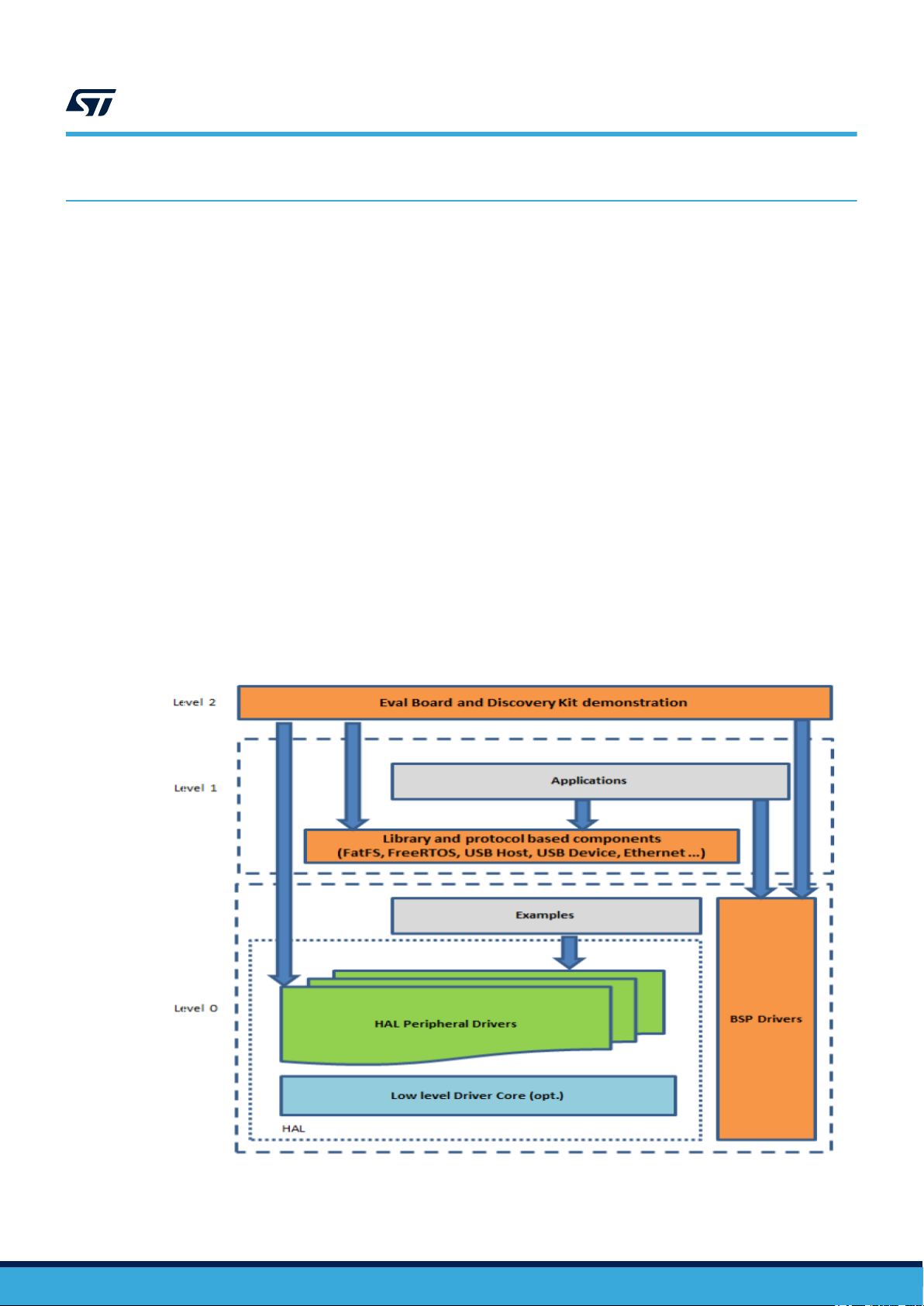
2.2 STM32Cube architecture
The STM32Cube firmware solution is built around three independent levels that can easily interact with each
other as illustrated in the figure below:
Figure 1. Firmware architecture
UM2812 - Rev 1
page 3/13
Page 4

UM2812
STM32Cube architecture
Level 0
This level is divided into three sublayers:
• Board Support Package (BSP): this layer offers a set of APIs relative to the hardware components in the
hardware boards (Audio codec, IO expander, Touchscreen, SRAM driver, LCD drivers. etc…) and composed
of two parts:
– Component: is the driver relative to the external device on the board and not related to the STM32, the
component driver provide specific APIs to the BSP driver external components and could be portable
on any other board.
– BSP driver: it permits to link the component driver to a specific board and provides a set of friendly
used APIs. The APIs naming rule is BSP_FUNCT_Action(): e.g. BSP_LED_Init(),BSP_LED_On()
It’s based on modular architecture allowing to port it easily on any hardware by justimplementing the
low level routines.
• Hardware Abstraction Layer (HAL): this layer provides the low level drivers and the hardware interfacing
methods to interact with the upper layers (application, libraries and stacks). It provides a generic, multi
instance and functionality oriented APIs which permit to offload the user application implementation by
providing ready to use process. For example, for the communication peripherals (I2S, UART…) it provides
APIs allowing to initialize and configure the peripheral, manage data transfer based on polling, interrupt or
DMA process, and manage communication errors that may raise during communication. The HAL drivers
APIs are split in two categories:
– generic APIs which provide common and generic functions to all the STM32 series
– extension APIs which provide specific and customized functions for a specific family or a specific part
number
• Basic peripheral usage examples: this layer encloses the examples build over the STM32 peripheral using
only the HAL and BSP resources.
Level 1
This level is divided into two sublayers:
• Middleware components: set of libraries covering USB host and device libraries, STemWin, FreeRTOS,
FatFS, LwIP, and PolarSSL. Horizontal interactions between the components of this layer is done directly by
calling the feature APIs, while the vertical interaction with the low level drivers is done through specific
callbacks and static macros implemented in the library system call interface. For example, the FatFs
implements the disk I/O driver to access microSD drive or the USB mass storage class.
• Examples based on the middleware components: each middleware component comes with one or more
example (called also applications) showing how to use it. Integration examples that use several middleware
components are provided as well.
Level 2
This level is composed of a single layer which is global real-time and graphical demonstration based on the
middleware service layer, the low level abstraction layer and the basic peripheral usage applications for board
based functionalities.
UM2812 - Rev 1
page 4/13
Page 5

X-CUBE-53L3A2 expansion software for STM32Cube
3 X-CUBE-53L3A2 expansion software for STM32Cube
3.1 Overview
X-CUBE-53L3A2 is a software package that expands the functionality provided by STM32Cube.
The key features of the package are:
• Complete software set to build the applications using the VL53L3CX ToF ranging sensor
• Easy portability across different MCU families
• Sample application to transmit real time sensor ranging data to a serial terminal
• Free user friendly license terms
• An implementation example available for the X-NUCLEO-53L3A2 running with a NUCLEOF401RE or
NUCLEO-L476RG
This software enables the ranging operation, running on STM32.
The package includes a sample application that the developer can use to start experimenting with the code. The
sample application performs the ranging operation and sends the ranging data to a PC.
UM2812
3.2 Architecture
This software is an expansion for STM32Cube, as such it fully complies with the architecture of STM32Cube and
it expands it in order to enable development of applications using ToF sensor. Refer to Section 2.2 STM32Cube
architecture for information regarding the STM32Cube architecture.
The software is based on the STM32CubeHAL, the hardware abstraction layer for the STM32 microcontroller. The
package extends STM32Cube by providing a Board Support Package (BSP) for the sensors expansion board and
some middleware components for serial communication with a PC.
The software layers used by the application software to access and use the sensors expansion board are the
following:
• STM32Cube HAL layer: The HAL driver layer provides a generic multi instance simple set of APIs
(application programming interfaces) to interact with the upper layers (application, libraries and stacks).
It is composed of generic and extension APIs. It is directly built around a generic architecture and allows
the layers that are built upon, such as the middleware layer, to implement their functionalities without
dependencies on the specific hardware configuration for a given microcontroller unit (MCU). This structure
improves the library code reusability and guarantees an easy portability on other devices.
• BSP layer: The software package needs to support the peripherals on the STM32 nucleo board apart from
the MCU. This software is included in the board support package (BSP). This is a limited set of APIs which
provides a programming interface for certain board specific peripherals, e.g. the LED, the user button etc.
This interface also helps identify the specific board version.
The following figure outlines the software architecture of the package:
UM2812 - Rev 1
page 5/13
Page 6

Figure 2. X-CUBE-53L3A2 software architecture
UM2812
Folder structure
3.3 Folder structure
This section provides an overview of the package folders structure.
The next figure illustrates the architecture of the package
The following folders are included in the software package:
• Documentation: this folder contains a compiled HTML file generated from the source code and
documentating in details the software components and APIs.
• Drivers: this folder contains the HAL drivers, the board specific drivers for each supported board or hardware
platform, including the on board components ones and the CMSIS layer which is a vendor independent
hardware abstraction layer for the Cortex-M processor series.
• Projects: this folder contains a sample application used to access sensors data, provided for the
NUCLEO-F401RE and NUCLEO-L476RG platforms with three development environments (IAR, Keil and
STM32CubeIDE).
Figure 3. X-CUBE-53L3A2 package folder structure
3.4
UM2812 - Rev 1
APIs
Detailed technical information about the APIs available to the user can be found in a compiled HTML file
located inside the Documentation folder of the software package where all the functions and parameters are fully
described.
page 6/13
Page 7

3.5 Sample application description
An example application using the X-NUCLEO-53L3A2 expansion board with either NUCLEOF401RE or
NUCLEO-L476RG boards is provided in the “Projects” directory. Ready to be built projects are available for
the three IDEs (IAR. Keil and STM32CubeIDE).
In the following sample application, real-time sensor ranging data is transmitted to a PC via serial port, using the
HAL_UART_Transmit() system call. Transmitted sensor data can be viewed using the Tera Term.
In the sample return above:
• Count = 128 is the ranging number
• #Objs = is the number of detected objets (in this case 2)
• status=0 indicates there are no errors
• D=117 mm is the distance of the first detected object
• D=1025 mm is the distance of the second detected objet
UM2812
Sample application description
Figure 4. Sample return
UM2812 - Rev 1
page 7/13
Page 8

4 System setup
4.1 Hardware description
This section describes the hardware components needed for developing a sensors based application.
The following sections describe the individual components.
4.1.1 STM32 Nucleo platform
The STM32 Nucleo boards provide an affordable and flexible way for users to try out new ideas and build
prototypes with any STM32 microcontroller lines. The Arduino® connectivity support and ST morpho headers
make it easy to expand the functionality of the STM32 Nucleo open development platform with a wide choice of
specialized expansion boards. The STM32 Nucleo board does not require any separate probe as it integrates the
ST-LINK/V2-1 debugger/programmer. The STM32 Nucleo board comes with the STM32 comprehensive software
HAL library together with various packaged software examples.
Information about the STM32 Nucleo boards is available on www.st.com at http://www.st.com/stm32nucleo
UM2812
System setup
Figure 5. STM32 Nucleo board
4.1.2 X-Nucleo-53L3A2 expansion board
The X-NUCLEO-53L3A2 is a ToF ranging sensor expansion board usable with a STM32 Nucleo development
board. It is also compatible with Arduino UNO R3 connector layout. The XNUCLEO-53L3A2 interfaces with the
STM32 MCU via I2C.
UM2812 - Rev 1
page 8/13
Page 9

Figure 6. X-Nucleo-53L3A2 expansion board
UM2812
Hardware description
Information about the X-NUCLEO-53L3A2 expansion board is available on www.st.com at http://www.st.com/xnucleo
Figure 7. X-NUCLEO-53L3A2 expansion board connected to STM32 Nucleo board
UM2812 - Rev 1
page 9/13
Page 10

4.2 Software description
The following software components are required in order to setup the suitable development environment to create
the applications running on the STM32 Nucleo and the ToF sensor expansion board:
• X-CUBE-53L3A2: a software expansion for STM32Cube dedicated to sensors applications development.
The X-CUBE-53L3A2 firmware and related documentation is available on st.com.
• Development tool chain and compiler: The STM32Cube expansion software supports the three following
environments:
– IAR + ST-Link
– KEIL + ST-LINK
– STM32CubeIDE + ST-LINK
4.3 Hardware and software setup
This section describes the hardware and software setup procedures. It also describes the system setup needed
for the above.
4.3.1 Hardware setup
The following hardware components are needed:
• a STM32 Nucleo development platform (suggested order code: either NUCLEOF401RE or NUCLEOL053R8)
• a sensor expansion board (order code: X-NUCLEO-53L3A2)
• a USB type A to Mini-B USB cable to connect the STM32 Nucleo to the PC
UM2812
Software description
4.3.2 Software setup
This section lists the minimum requirements for the developer to setup the SDK, run the sample testing scenario
based on the GUI utility and customize applications.
4.3.2.1 Development tool chain and compiler
Select one of the Integrated Development Environments supported by the STM32Cube expansion software.
Read the system requirements and setup information provided by the selected IDE provider.
4.3.2.2 PC utility
The Sensors_DataLog utility for PC has the following minimum requirements:
• PC with Intel or AMD processor running one of following Microsoft operating system:
– Windows 10
– Windows 7
• At least 128 MBs of RAM
• Two USB ports
• 40 MB of hard disk space
4.4
STM32 Nucleo and sensor expansion board setup
The STM32 Nucleo board integrates the ST-LINK/V2-1 debugger/programmer.
If Windows cannot install automatically the STLINK driver, the developer can download the ST-LINK/V2-1 USB
driver by looking at the STSW-LINK009 software on www.st.com.
The developer needs to unzip the file and run the "stlink_winusb_install.bat" to install the STLINK driver.
The sensors expansion board X-NUCLEO-53L3A2 can be easily connected to the STM32 Nucleo motherboard
through the Arduino UNO R3 extension connector (see X-NUCLEO-53L3A2 expansion board connected to
STM32 Nucleo board). The sensor expansion board can interface with the external STM32 microcontroller on
STM32 Nucleo using inter-integrated circuit (I2C) transport layer.
UM2812 - Rev 1
page 10/13
Page 11

Revision history
UM2812
Table 1. Document revision history
Date Version Changes
08-Jan-2021 1 Initial release
UM2812 - Rev 1
page 11/13
Page 12

UM2812
Contents
Contents
1 Acronyms and abbreviations ......................................................2
2 What is STM32Cube? ..............................................................3
2.1 STM32Cube overview ..........................................................3
2.2 STM32Cube architecture ........................................................3
3 X-CUBE-53L3A2 expansion software for STM32Cube...............................5
3.1 Overview .....................................................................5
3.2 Architecture ...................................................................5
3.3 Folder structure ................................................................6
3.4 APIs .........................................................................6
3.5 Sample application description ...................................................7
4 System setup......................................................................8
4.1 Hardware description ...........................................................8
4.1.1 STM32 Nucleo platform ...................................................8
4.1.2 X-Nucleo-53L3A2 expansion board...........................................8
4.2 Software description ...........................................................10
4.3 Hardware and software setup ...................................................10
4.3.1 Hardware setup.........................................................10
4.3.2 Software setup .........................................................10
4.4 STM32 Nucleo and sensor expansion board setup .................................10
Revision history .......................................................................11
Contents ..............................................................................12
UM2812 - Rev 1
page 12/13
Page 13

UM2812
IMPORTANT NOTICE – PLEASE READ CAREFULLY
STMicroelectronics NV and its subsidiaries (“ST”) reserve the right to make changes, corrections, enhancements, modifications, and improvements to ST
products and/or to this document at any time without notice. Purchasers should obtain the latest relevant information on ST products before placing orders. ST
products are sold pursuant to ST’s terms and conditions of sale in place at the time of order acknowledgement.
Purchasers are solely responsible for the choice, selection, and use of ST products and ST assumes no liability for application assistance or the design of
Purchasers’ products.
No license, express or implied, to any intellectual property right is granted by ST herein.
Resale of ST products with provisions different from the information set forth herein shall void any warranty granted by ST for such product.
ST and the ST logo are trademarks of ST. For additional information about ST trademarks, please refer to www.st.com/trademarks. All other product or service
names are the property of their respective owners.
Information in this document supersedes and replaces information previously supplied in any prior versions of this document.
© 2021 STMicroelectronics – All rights reserved
UM2812 - Rev 1
page 13/13
 Loading...