

Page 1

UM2600
User manual
Counting people with the VL53L1X long-distance ranging Time-of-Flight sensor
Introduction
This user manual explains how to use a VL53L1X long-distance ranging Time-of-Flight (ToF) sensor to count people crossing a
specific predefined area, like a meeting room entrance or a particular location in a corridor. It also describes an algorithm used
to count the people. The algorithm is provided as an example and can be downloaded from st.com, in the VL53L1X embedded
SW section, under the reference STSW-IMG010.
In addition, this document presents the details of a counting application where a sensor is set on the top, not the side, of the
area to be tracked.
UM2600 - Rev 2 - December 2020
For further information contact your local STMicroelectronics sales office.
www.st.com
Page 2

1 Acronyms and abbreviations
Table 1. Acronyms and abbreviations
Acronym/abbreviation Definition
FoV field of view
SPAD single photon avalanche diode
SW software
ToF Time-of-Flight
UM2600
Acronyms and abbreviations
UM2600 - Rev 2
page 2/15
Page 3
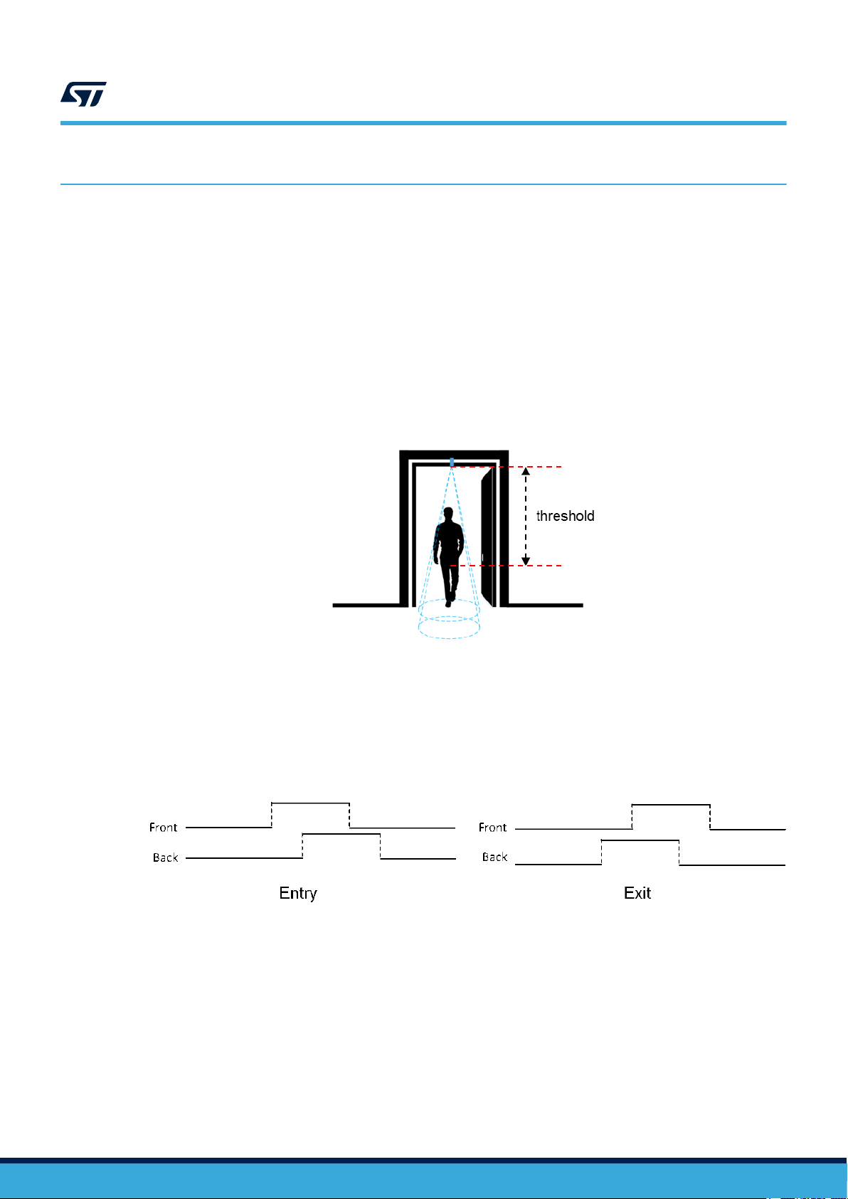
2 Overview
Counting people with the VL53L1X consists of using the multiple zones of the sensor receiving SPAD area,
and of configuring it with two distinct fields of view (FoV), to alternatively get a ranging distance from them
and consequently recognize the movements of a person. Using this method, the number of people occupying a
meeting room, accessible from a reasonably narrow access, is known at all times by detecting the entrances and
exits of the attendees.
By measuring and analyzing the distances of targets within the FoVs of a front and back zone (see figure below
and Figure 3. Front and back zones), a simple algorithm can detect the direction a person crosses the area
under the two FoVs. This algorithm "understands" that someone is under one of the FoV as long as the distance
measured by the sensor under this FoV is between 0 and a threshold value specified in mm.
UM2600
Overview
Figure 1. VL53L1X FoV divided in two subfields of view
From a timing perspective, the sensor alternatively ranges on each of the two zones, for a very short period of
time in milliseconds. It is possible to determine in which direction a person crosses the area, depending in which
order this person has been detected in the two zones, as shown in the figure below.
Figure 2. Person counting chronogram
UM2600 - Rev 2
page 3/15
Page 4
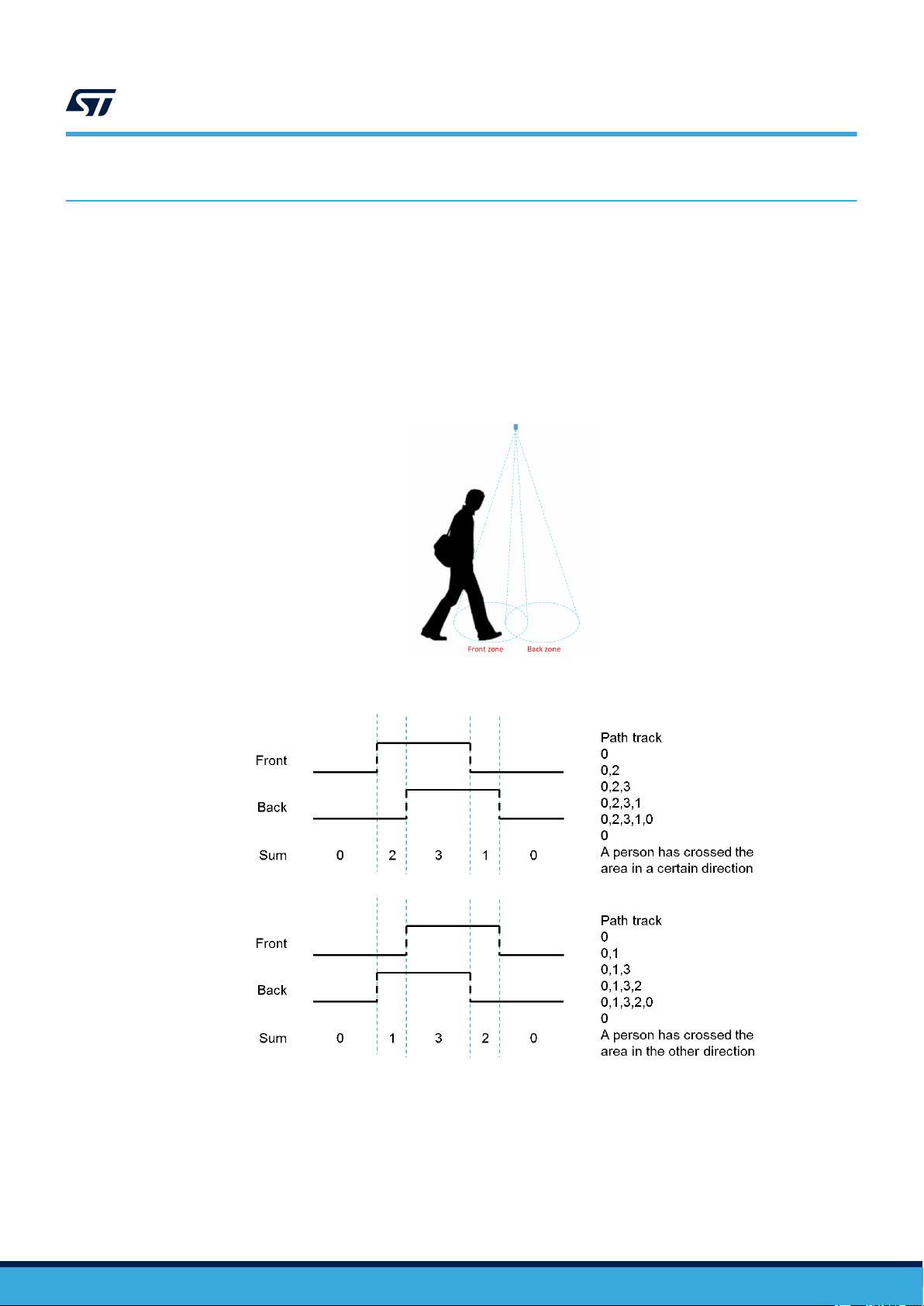
3 Algorithm description
The counting algorithm example relies on a list of states that have to occur in a certain order to detect if a person
has crossed the specified area and in which direction this area has been crossed. These states are stored in a
list and compared to two default lists of states that represent how the area is crossed in two different directions.
When no-one is seen in either of the two zones, the list of states is reset.
If we consider that a person detected in the front zone equals 2, and a person detected in the back zone equals 1,
the algorithm adds the value of the two states and stores the result as soon as it changes.
Eventually, if the consecutive states in the list are 0, 1, 3, 2, 0 or 0, 2, 3, 1, 0 this means a person has been
detected in one direction or the other, as described in Figure 4. List of status values.
UM2600
Algorithm description
Figure 3. Front and back zones
Figure 4. List of status values
UM2600 - Rev 2
page 4/15
Page 5
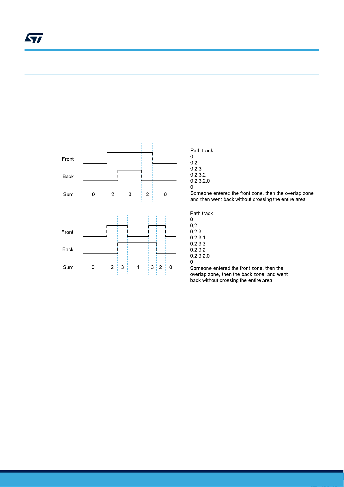
4 Hysteresis
The algorithm validates a crossing event only when a person has fully crossed the two zones. It does not validate
the event when the person remains for a long time under the FoV or when the person decides to return from the
place he came from.
This is illustrated in the figure below: the algorithm stops and the list of states is reset as soon as no-one is
detected in any of the two FoVs.
UM2600
Hysteresis
Figure 5. Hysteresis principle
UM2600 - Rev 2
page 5/15
Page 6

VL53L1X sensor and algorithm configuration
5 VL53L1X sensor and algorithm configuration
It is sufficient to set the two FoVs by dividing the 16*16 SPAD array of the VL53L1X sensor into two sub N*16
arrays. For example, N can be chosen within the interval [4, 8]. This means that it is not necessary to use the
same SPADs for front and back ranging. Alternatively enabling 7*16 SPADs is sufficient to see a person in the
two zones at the same time when this person stands directly under the sensor, in the middle of the two FoVs. It is
recommended to configure the sensor to range alternatively on the two zones every 20 ms.
Figure 6. Example of configuration of the SPAD array
UM2600
The figure below shows the captured distances from two zones, where the VL53L1X is set at 2600 mm from the
floor. The black arrows correspond to the times when a person was detected entering or exiting the area being
tracked. Three crossings are visible. The first two arrows correspond to two entries and the last one corresponds
to an exit. The red and blue dots are distances measured by the sensor from the front and back zones.
Figure 7. Example of captured distances
UM2600 - Rev 2
page 6/15
Page 7

UM2600
Setup reliability
6 Setup reliability
6.1 Ranging on the floor to determine the threshold
Reliability of the algorithm relies on the accuracy of the setup which detects the distance between the sensor
and the floor. This can be ensured only if nothing (e.g. no obstacle or static object) blocks the front and back
FoVs. To assess if a setup is reliable, a significant number of distances can be measured with the sensor. Then, a
histogram diagram can be established to confirm that the sensor is correctly set up and that no target is within its
FoVs.
A threshold needs to be defined, which is achieved after having ranged on the flooring material over a significant
number of samples. In fact, the threshold should be chosen so that all the measured distances (when ranging
the floor) are greater than this threshold. We recommend that at installation of the application, an autocalibration
routine is launched to calculate the threshold. This is because flooring material can be different in many locations.
Figure 9. Histogram of 3500 measured distances describes an example of such a calibration for the use case
illustrated in Figure 8. People counting at 2345 mm distance from the floor. The distance between the sensor and
the floor is 2345 mm, and as the minimum distance measured by the sensor is 2290 mm, the threshold is thus
less than 2290 mm.
Note: This calibration should be performed in the worst ambient light conditions, to maximize the jitter and obtain a
threshold that is relevant to all possible ambient lighting conditions the counting setup is exposed to.
Figure 8. People counting at 2345 mm distance from the floor
UM2600 - Rev 2
page 7/15
Page 8

Ranging on the floor to determine the threshold
Figure 9. Histogram of 3500 measured distances
UM2600
Note: The mean of the measured distances, in case it equals the real distance between the sensor and the floor, is an
indication of the reliability of the setup.
In Figure 10. Reliable setup, the mean of the measured distances from the two zones are the same and equals
the real distance between the sensor and the floor, which is 2600 mm. This indicates a reliable setup. Here, the
threshold is less than 1920 mm.
Figure 10. Reliable setup
UM2600 - Rev 2
page 8/15
Page 9

UM2600
Ranging on the floor to determine the threshold
A setup is considered good if the sensor detects only the floor in the two FoVs. Consequently, the verticality of the
FoV is ensured. However, the tracking area must not be too narrow. In situations where the verticality cannot be
fully ensured, or when the FoVs are narrow, it is advised to alternatively enable N*M SPADs as follows:
• N to be within the interval [4, 8] as described above and enabled SPADs should be centered
• M to be within the interval [8, 16] and the SPADs to remain centered for a narrow but non vertical setup. If
the verticality of the FoV cannot be ensured, the SPADs do not have to be centered.
Floor detection reliability can be checked by running a trimming procedure to adjust the width of the back and
front FoVs, by enabling the relevant SPADs. Analysis of the extracted histograms can help in detecting the SPADs
belonging to the parts of the FoVs that do not range on the floor and should never be enabled. Note that the
smaller the number of lines of SPADs used for this trimming, the larger the number of histogram values that have
to be computed.
The figure below shows a trimming procedure example in which a significant number of distances have been
extracted by ranging with the SPADs enabled within the red rectangle (10 SPADs lines). The red rectangle can be
moved by one line or more between each test.
Figure 11. Trimming procedure
UM2600 - Rev 2
page 9/15
Page 10

6.2 Ensure overlap in the two detection zones
The algorithm example relies on the fact that a person crossing an area being tracked must first be detected
in the first zone, then in both zones at the same time, and finally in the second zone. In Figure 7. Example
of captured distances, both tracking paths have a few dots corresponding to the moment when a person was
detected in both zones simultaneously. Increasing N, increases this number of dots, but could decrease the
number of dots corresponding to the time when a person is detected only in the first or second zone.
To optimize the behavior of the algorithm, it is advised to choose N as small as possible and to apply a
filter, on the detected distances, which consists of considering only the minimum distance value from the last
Z measurements, up to the time where a person is detected in the last zone. This significantly optimizes the
probability of detecting a person in each of the zones of the tracking path.
The figure below shows the well-defined detection of a person in each of the three zones.
Figure 12. Filter on the measured distances with Z = 10, N = 6, M = 16
UM2600
Ensure overlap in the two detection zones
UM2600 - Rev 2
page 10/15
Page 11

7 Example: long black hair
A long dark hair returns much less photons that a blond hair. Therefore, the reflected signal is lower and the
reported distance may be bigger than the real distance, since the device gets a mixed signal of photons that have
bounced on the hair of the tracked person and on the floor.
Figure 13. Example of a fast moving person with long black hairshows an example of a fast moving person
with long black hair. In this case, the algorithm does not count the person if the threshold is set with the value
corresponding to the red line. It is recommended to set a threshold at its maximum possible value, but still less
than the minimum value reported by the autocalibration, as described in Section 6.1 Ranging on the floor to
determine the threshold.
Figure 13. Example of a fast moving person with long black hair
UM2600
Example: long black hair
UM2600 - Rev 2
page 11/15
Page 12
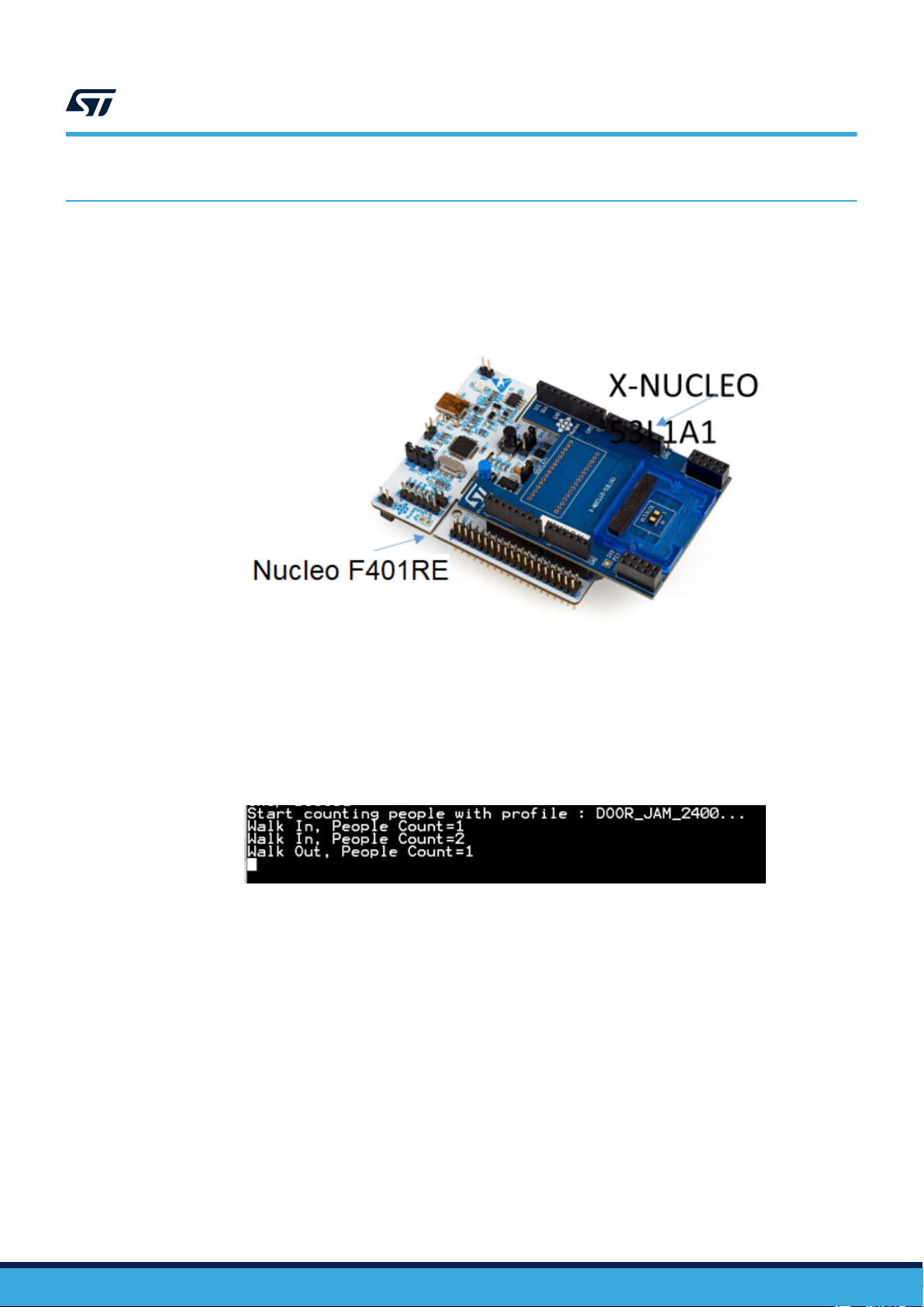
8 Software and board package
The software example runs a proof of concept, implementing the algorithm as described above. This software
runs on a NUCLEO F401RE board, accompanied by one X-NUCLEO-53L1A1 expansion board (see figure
below).
Figure 14. NUCLEO FR01RE board and X-NUCLEO-53L1A1 expansion board
UM2600
Software and board package
To operate,
• Place the device without any object within 2 m in front of the ToF sensor
• Wave your arm in front of the sensor from left to right and from right to left at a distance ~50 cm
• the people counting result displays as shown in the figure below (in Tera term)
• The serial baud rate is set at the 460800 bauds per second
Figure 15. Tera term
UM2600 - Rev 2
page 12/15
Page 13

Revision history
Table 2. Document revision history
Date Version Changes
26-Jun-2019 1 Initial release
Section 3 Algorithm description: updated cross references to figures.
Section 5 VL53L1X sensor and algorithm configuration: added content.
Section 6.1 Ranging on the floor to determine the threshold: added new
content and figures; removed original "reliable" and "unreliable" figures.
18-Dec-2020 2
Section 6.2 Ensure overlap in the two detection zones: removed some text.
Added Section 7 Example: long black hair
Section 8 Software and board package: removed original content (and
added to Section 5 VL53L1X sensor and algorithm configuration), added
new content, and moved this section to end of document.
UM2600
UM2600 - Rev 2
page 13/15
Page 14

UM2600
Contents
Contents
1 Acronyms and abbreviations ......................................................2
2 Overview ..........................................................................3
3 Algorithm description..............................................................4
4 Hysteresis .........................................................................5
5 VL53L1X sensor and algorithm configuration ......................................6
6 Setup reliability....................................................................7
6.1 Ranging on the floor to determine the threshold .....................................7
6.2 Ensure overlap in the two detection zones ........................................10
7 Example: long black hair..........................................................11
8 Software and board package......................................................12
Revision history .......................................................................13
Contents ..............................................................................14
UM2600 - Rev 2
page 14/15
Page 15

UM2600
IMPORTANT NOTICE – PLEASE READ CAREFULLY
STMicroelectronics NV and its subsidiaries (“ST”) reserve the right to make changes, corrections, enhancements, modifications, and improvements to ST
products and/or to this document at any time without notice. Purchasers should obtain the latest relevant information on ST products before placing orders. ST
products are sold pursuant to ST’s terms and conditions of sale in place at the time of order acknowledgement.
Purchasers are solely responsible for the choice, selection, and use of ST products and ST assumes no liability for application assistance or the design of
Purchasers’ products.
No license, express or implied, to any intellectual property right is granted by ST herein.
Resale of ST products with provisions different from the information set forth herein shall void any warranty granted by ST for such product.
ST and the ST logo are trademarks of ST. For additional information about ST trademarks, please refer to www.st.com/trademarks. All other product or service
names are the property of their respective owners.
Information in this document supersedes and replaces information previously supplied in any prior versions of this document.
© 2020 STMicroelectronics – All rights reserved
UM2600 - Rev 2
page 15/15
 Loading...