

Page 1
UM2800
User manual
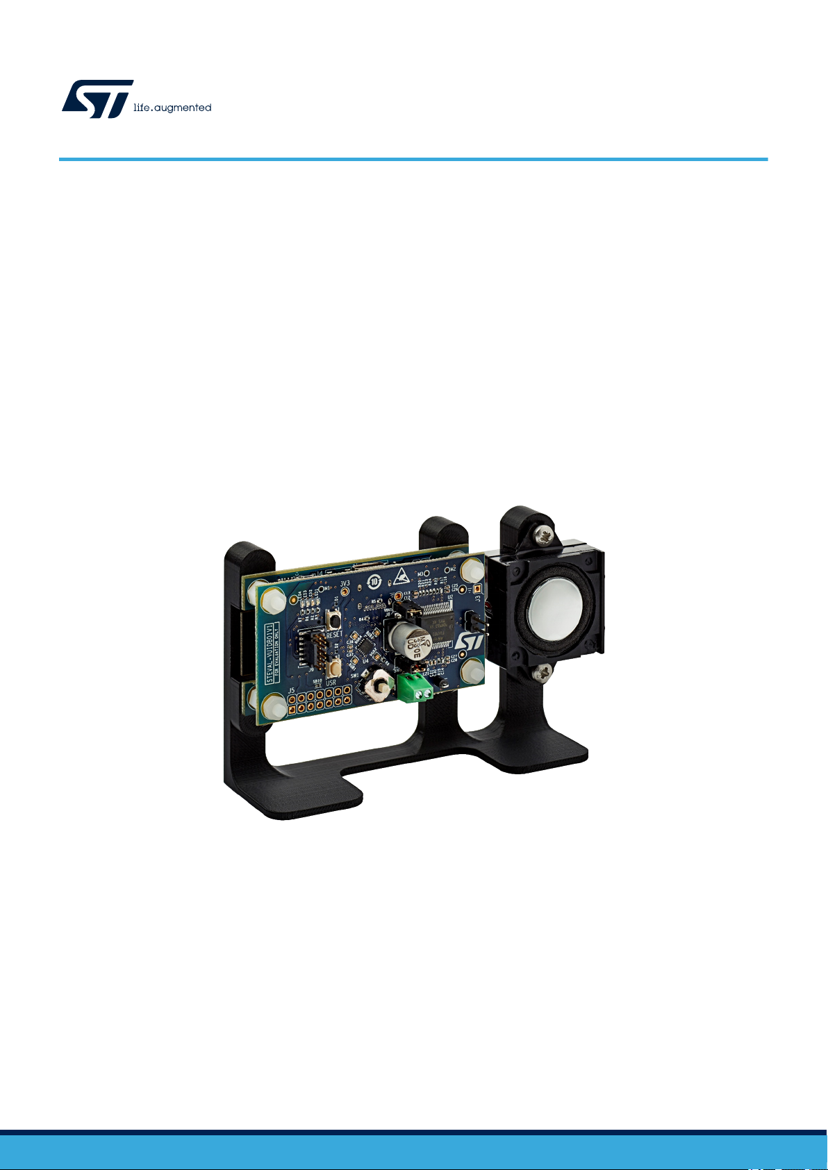
Getting started with the STEVAL-VOICE-UI voice user interface evaluation kit
Introduction
The STEVAL-VOICE-UI Amazon™ qualified evaluation kit is designed to allow evaluation of a cost-effective way to integrate
AVS for AWS IoT Services® into smart devices, so they can implement state-of-art, hands-free voice control based on natural
language comprehension.
Users will therefore enjoy a heightened experience with target IoT end products, with the ability to talk to Amazon Alexa and
control smart home devices, get assistance, listen to the news, check the weather forecast, play music, etc.
The software package implements audio front-end, Amazon wake word, audio playback and Amazon Alexa® communication
protocol software. The SDK runs on internal memories only, offering maximum integration and cost-effective solutions.
The STEVAL-VOICE-UI is built with a modular approach for easy prototyping and debugging purposes as well as easy
adaptation to specific microphone spacings, user interface and audio output requirements.
Figure 1. STEVAL-VOICE-UI voice user interface evaluation kit
UM2800 - Rev 1 - November 2020
For further information contact your local STMicroelectronics sales office.
www.st.com
Page 2
1 Overview
Cortex-M7F@480MHz
1MB RAM
2MB Flash
STM32H753VIT6E
700mA DC-DC
SPI
Murata 1DX
2MB NOR
Flash
STDC14
Led driver
UART
PDM
Joystick
I2C
40pin
conn
(CN1)
USB-C
STSAFE
I2C
Wi-Fi Module
Wi-Fi sub-system
4 LED
(bypass mode)
Audio OUT
ISSI IS25LP016D
I2S
PDM
I2C
UART
STEVAL-VUIDB01V1STEVAL-VUIMB02V1
I2C
I2S
ST1S12GR
LED
4x RGB
2x Buttons
Speaker
output
connector
LED1202
FDA903D
MP23DB01HP
Digital microphone
(Optional)
(Optional)
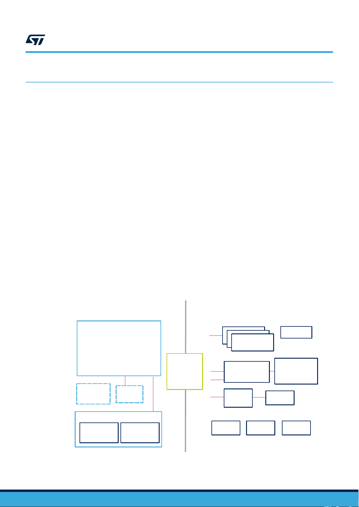
The STEVAL-VOICE-UI kit features:
• STM32H753VIT6E high-performance MCU with 2 MB embedded Flash, 1 Mb embedded SRAM and in
cost-effective LQFP package
• 2.4 GHz Wi-Fi subsystem with Murata 1DX module used in bypass mode coupled to ISSI IS25LP016D 2
MBytes NOR Flash memory
• 3 x MP23DB01HP MEMS microphones with 36 and 30 mm spacing
• FDA903D class D digital input automotive audio amplifier
• 8 Ohm loudspeaker
• 4 RGB LEDs and 4 simple LEDs
• Joystick, reset and user push buttons
• High modularity with mother/daughter board
• Small 36x65 mm² footprint with simple and cost-effective PCB design
1.1 Kit components
The STEVAL-VOICE-UI kit package includes:
• STEVAL-VUIMB02V1: VUI mother board embedding the STM32H753VIT6E MCU and the Wi-Fi module
• STEVAL-VUIDB01V1: VUI daughter board including the audio front-end (MP23DB01HP microphones and
FDA903D audio amplifier) and the user interface (buttons, joystick, LEDs and USB)
• 8 Ohm speaker
• Mechanical parts
• STLINK-V3MINI debugger/programmer for STM32 with programming cable
• A to C connector cable
UM2800
Overview
1.2
UM2800 - Rev 1
Functional block diagram
Figure 2. STEVAL-VOICE-UI functional block diagram
page 2/34
Page 3
1.3 System requirements
U4
STM32H7
VBUS
J1
MP23DB01HP
LED1202
USB-C
J2
5V
V_PA
STEVAL-VUIMB01V1
Wi-Fi sub-module
STSAFE
FDA903D
Audio Amplifier
STEVAL-VUIDB02V1
Murata 1DX
2MB NOR
3V3
ST1S12
J8
UM2800
System requirements
• Windows® OS (7, 8 and 10), Linux® 64-bit, or MacOS
• html5 web browser version
• Companion app requires Android 7
1.4 Development toolchains
• IAR Systems - IAR Embedded Workbench® EWARM
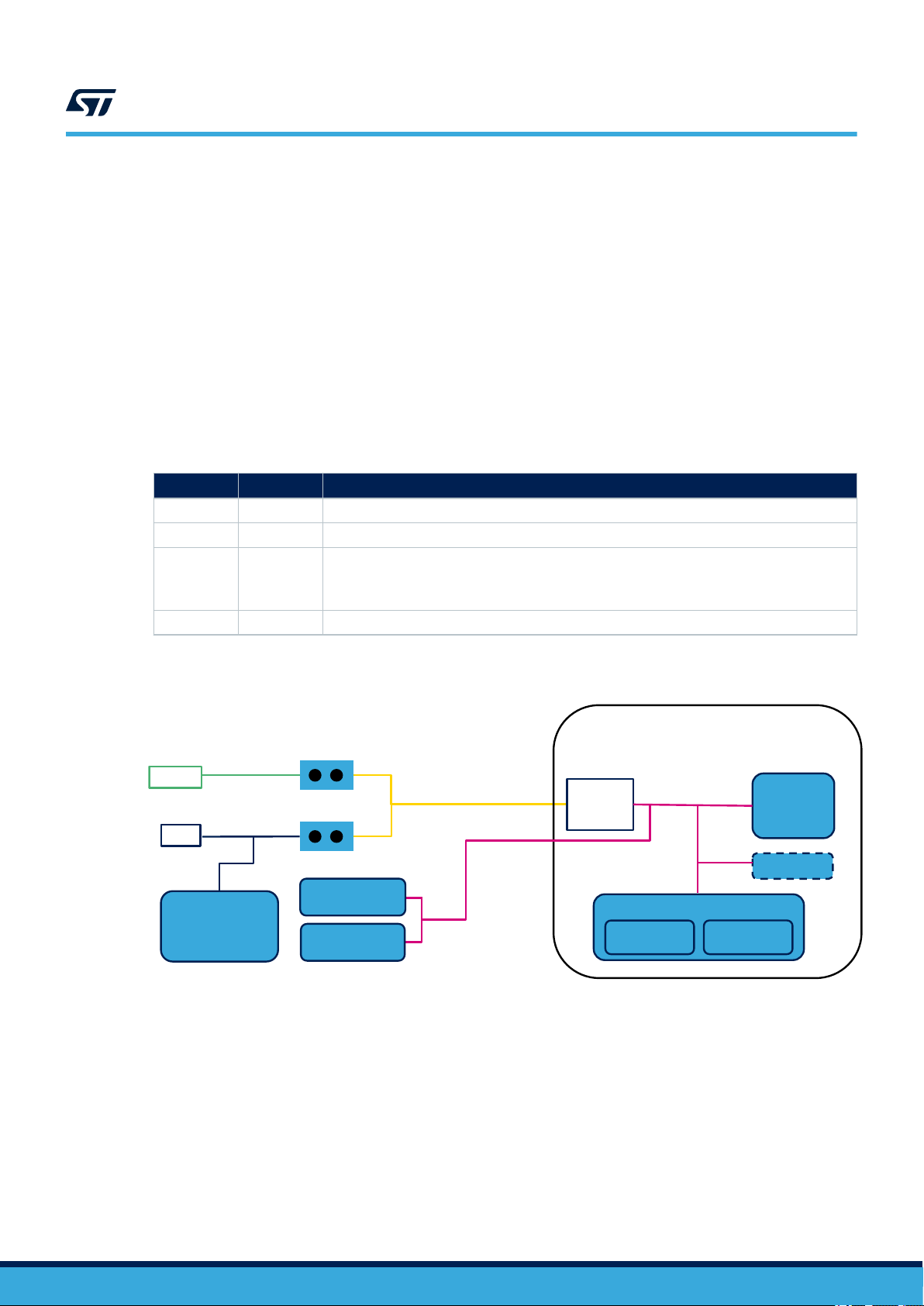
1.5 Power supply
The easiest way to power the STEVAL-VOICE-UI kit is via the USB-C connector.
J1 J8 Description
CLOSE CLOSE Single power supply from USB. Do not connect V_PA (J2)
CLOSE OPEN Single power supply from V_PA (J2) → up to 5 V
Dual power supply:
OPEN CLOSE
OPEN OPEN 5 V from external source (CN1)
• 5 V from USB
• V_PA from J2 → Up to 18 V
®
Table 1. Power supply options
Figure 3. STEVAL-VOICE-UI power supply block diagram
UM2800 - Rev 1
page 3/34
Page 4
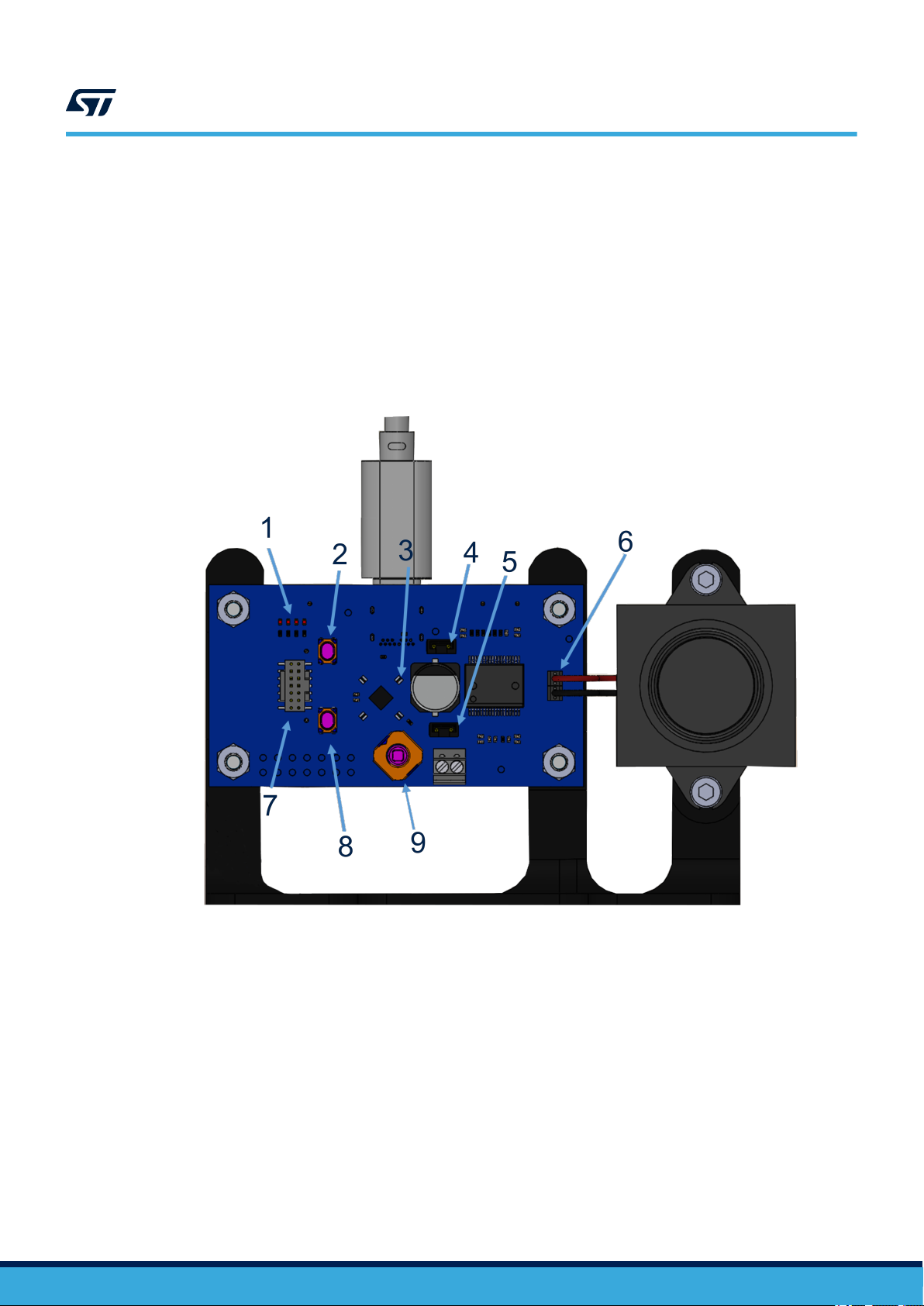
1.6 User interfaces
1. 4 LEDs
2. Reset button
3. 4 RGB LEDs
4. J8
5. J1
6. Loudspeaker terminals
7. Programming connector (STDC14)
8. User button
9. Joystick
UM2800
User interfaces
Figure 4. STEVAL-VOICE-UI user interfaces
UM2800 - Rev 1
page 4/34
Page 5

2 Demo firmware
2.1 Pre-requisites
The pre-installed ST_VOICE_UI flashed demo firmware demonstrates a voice service solution able to connect to
AVS for AWS IoT.
A direct Internet connection is needed (without proxy).
As an Alexa® device, you need an Amazon™ account to connect to AVS for AWS IoT service.
The account can be created on www.amazon.com or other local versions.
The users who have registered to Amazon Music service will be able to play music on the device.
2.2 Device setup
Step 1. Power the device through a USB C cable.
Step 2. Configure the network connection.
Step 3. Register to AVS for AWS IoT service.
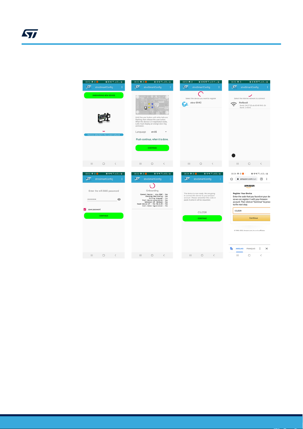
2.2.1 Android users
For Android users, the stvsSmartConfig companion app is available on Google Store and allows configuring the
device. The application is also available in the software delivery package for manual installation.
UM2800
Demo firmware
UM2800 - Rev 1
page 5/34
Page 6
UM2800
Device setup
Step 1. To configure a new device, push the [Onboarding new device] button and follow the instructions.
Figure 5. stvsSmartConfig procedure
2.2.2 Other users - HTTP UI
The device embeds an HTTP service that the consumer can connect to via smartphone or PC and an HTML5
browser (Safari or Chrome). To connect to the server, the smartphone must be connected to the same Wi-Fi spot
of the board.
The HTTP UI interface tab allows checking the service status and changing some configurations.
Two cases must be distinguished:
1. Wi-Fi connection
2. Other connections (Wi-Fi information already logged in)
2.2.2.1 Wi-Fi connection
Step 1. Ensure the device is in Access Point (AP) mode.
Step 1a. Check the current mode using the RGB LEDs (see Table 2).
Step 1b. If not in AP mode, refer to Section 2.9 .
Step 2. Connect your phone/PC navigator to 192.168.0.1.
Step 3. Follow the procedure described in Section 2.2.2.1.1 .
2.2.2.1.1 Wi-Fi configuration
By default, the device comes in Wi-Fi AP mode and offers a hotspot whose name looks like stvs-xxxx.
Step 1. Connect your PC or smartphone to the hotspot and then connect the browser to the address
192.168.0.1.
UM2800 - Rev 1
page 6/34
Page 7
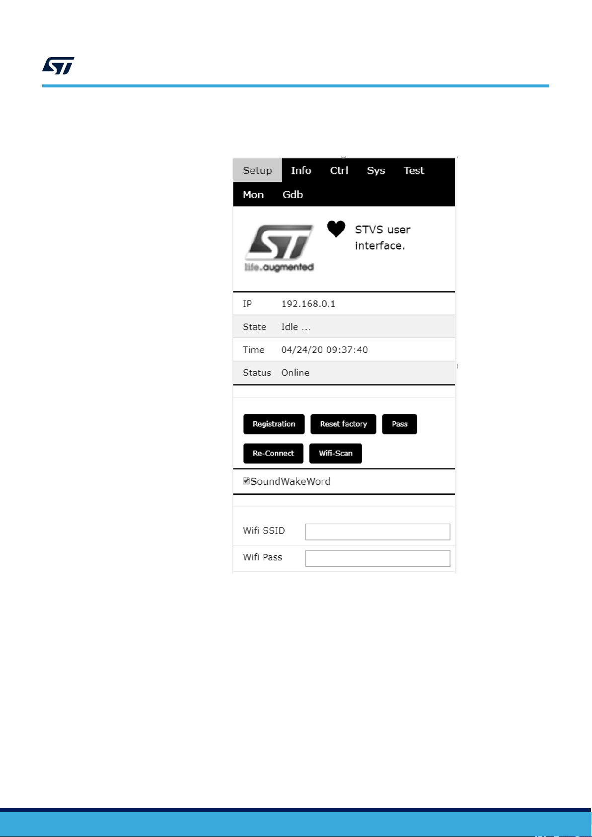
Step 2. Go to STVS UI [Setup] tab.
UM2800
Device setup
Figure 6. STVS user interface
2.2.2.2
UM2800 - Rev 1
Step 3. Push the [Wi-Fi-Scan] button.
All visible spots will be listed in the scan results.
Step 4. Scroll down and select your home network (in this case the hotspot is called [Netbook]).
Step 5. Scroll back and type the Wi-Fi password.
Step 6. Scroll down and select the connection type ([Wi-Fi STA].
Step 7. To connect the board, scroll up and select [Re-connect].
Step 8. Check RGB LEDs on the board (see Table 2).
After few seconds, the Wi-Fi state should switch from “disconnected” to “connected “.
The board reboots and connects to the network via Wi-Fi using a new IP address.
Connection to Wi-Fi STA
In this case, hotspot Wi-Fi information has already been configured and the board is properly connected to it
(refer to Section 2.2.2.1.1 , step 6).
page 7/34
Page 8

Step 1. Get the board IP address available in the serial console.
Step 2. Refer to Section 2.11 to access the traces.
Note: Traces with the IP address looks like:
00:00:00 : 192.168.X.X : 06:STVS_EVT_NETWORK_IP(0x3001D5BC)
The IP is no longer in the AP mode (address = 192.168.0.1).
Step 3. Connect to the UI using the given address.
Step 4. If there is no serial console connected to the board, scan the network using a free application.
Once installed, the application shows all STVS devices available in the neighborhood and allows
connecting to them:
– iPhone users can install “Bonjour HTTP search” from the App Store;
– Android users can download “BonjourBrowser” from the Android Store;
– PC users can install “bonjour browser” from www.tildesoft.com.
2.3 Device registration
Step 1. From www.amazon.com or local Amazon server, create an Amazon account.
UM2800
Device registration
Step 2. Under [Setup] tab, click [Registration](HTML5 browser required).
The browser will display a code and a link (amazon.com/code).
UM2800 - Rev 1
page 8/34
Page 9
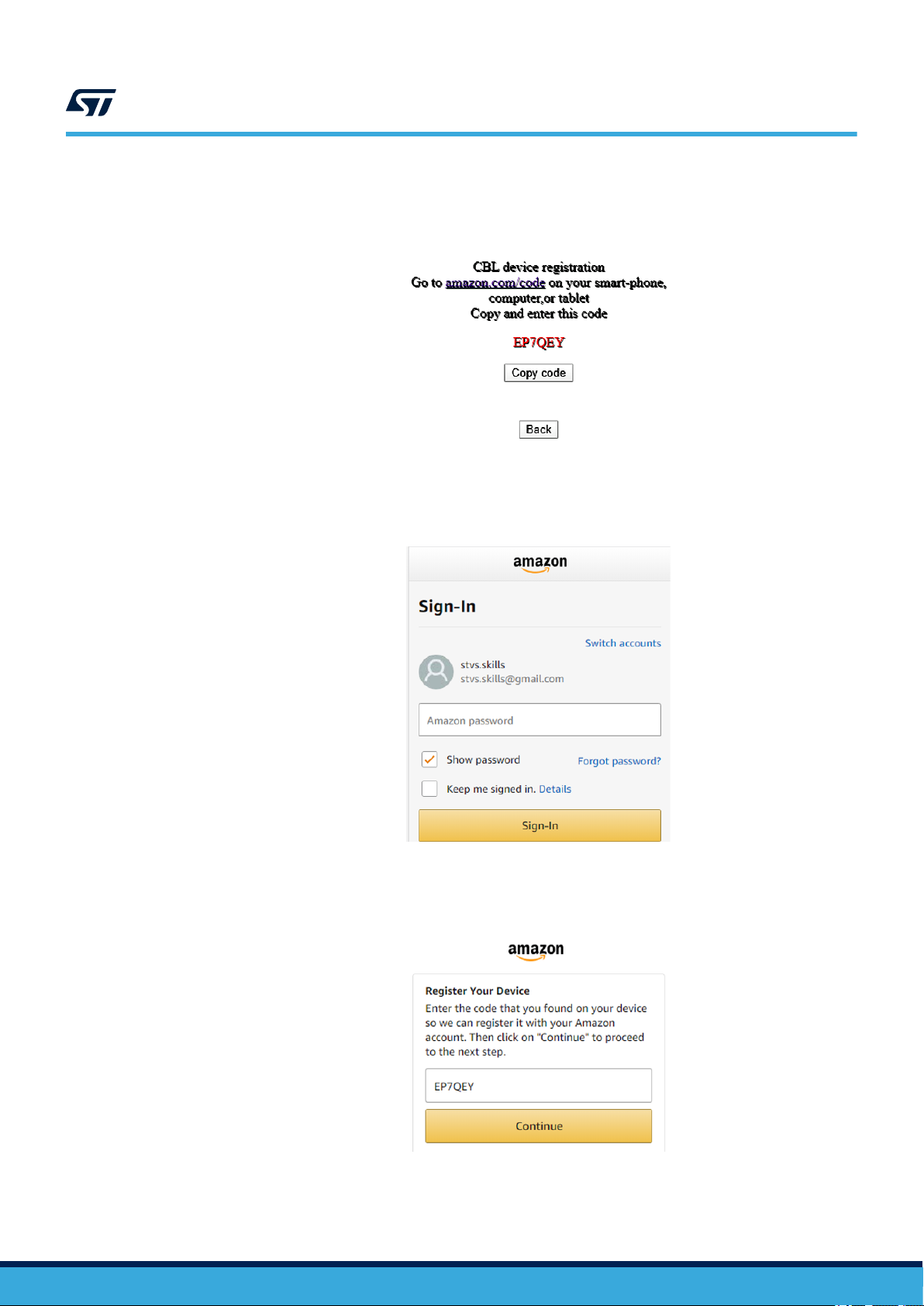
Step 3. Copy the code and click on the link.
Figure 7. CBL device registration code
You will be redirected to an Amazon sign-in page.
UM2800
Device registration
Figure 8. Amazon sign-in page
UM2800 - Rev 1
Step 4. Enter you Amazon credentials.
If credentials are correct, you will be redirected to the following page.
Figure 9. Register device page
page 9/34
Page 10
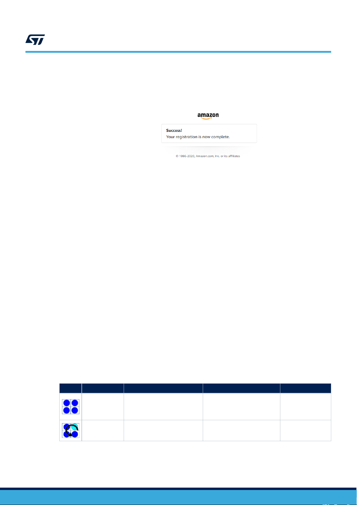
Step 5. Past or enter the code given in the previous page and click on continue.
If this step is successful, the board connects to AVS for AWS IoT and the LEDs turns off after few
seconds.
Now you can test the device. You can talk to Alexa (for example, asking: “Alexa, what time is it ?”)
2.4 Privacy mode
UM2800
Privacy mode
Figure 10. Successful registration
The device enters privacy mode when you briefly push the white user button.
A red LED switches on and the device does not send any other audio request to the cloud, even when saying
"Alexa".
2.5 Alarms
When an alarm or a timer is set and the device rings, you have to press the joystick to acknowledge and stop the
alert.
Example of voice requests:
• “Alexa set a timer for 2 minutes”;
• “Alexa set an alarm at 5 pm”;
• “Alexa set alarm” → Alexa will ask for details.
2.6 Amazon music control
If the Amazon account used to register the board is registered to Amazon music, it is possible to ask Alexa to play
some songs or playlists and navigate it.
The joystick is also used to navigate music playlists.
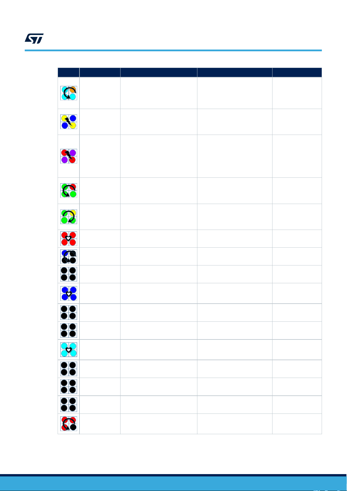
2.7 LED UI animations
Table 2. RGB LED animations indicating device state
Effects Color Internal service ID Animation Comment
Blue Restarting Solid
Blue/Cyan Booting Normal beat
Just after the reset.
It remains like this
until the first event is
dispatched.
It remains like this
during the basic
system initialization.
UM2800 - Rev 1
page 10/34
Page 11
UM2800
LED UI animations
Effects Color Internal service ID Animation Comment
It signals a
Cyan/Orange configuration_changes Normal beat
Blue/Yellow has_ip Very fast blinking
Red/Purple error_need_credentials Fast blinking
Green/Red
Yellow/Green connecting Fast counterclockwise rotation
error_need_registration Slow rotation
configuration state,
mainly when the
board is in Access
Point mode.
During the boot, it
signals by a sort
event that the network
has an IP address.
It signals an error,
the system needs
AWS and AVS
credentials. It should
occur only during
test and development
configuration.
It signals an error.
The system needs an
AVS registration (refer
to Section 2.3 ).
It signals a
reconnection to the
AVS for AWS IoT
service.
Red Privacy Very long pulsation
Blue/Black Wakeup Very fast rotation
Black Idle All off
Blue activeListening Very long pulsation
Black stopListening All off Not signalled yet.
Black startListening All off Not signalled yet.
Cyan activeSpeaking Very very long pulsation
Black stopSpeaking All off Not signalled yet.
Black startSpeaking All off Not signalled yet.
Black thinking All off Not signalled yet.
It signals the privacy
mode is ON.
Short signal when a
Wakeup occurs.
It signals the board is
ready for interactions.
The AVS for AWS IoT
service is listening for
utterance.
The AVS for AWS IoT
service is speaking or
playing.
UM2800 - Rev 1
Red/Black alerting Slow counterclockwise rotation
A timer/alarm/
notification/remember
is triggered.
page 11/34
Page 12
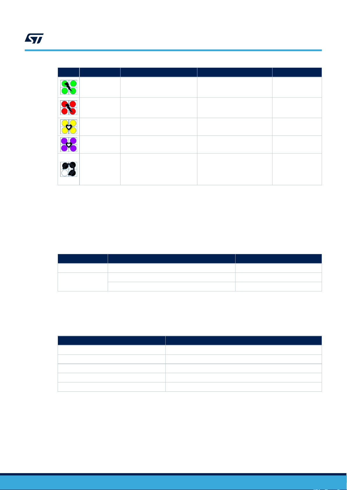
UM2800
Buttons and joystick
Effects Color Internal service ID Animation Comment
Green blinkGreen Slow blinking
Red blinkRed Slow blinking
It signals a
general purpose
event (Debug).
It signals a
general purpose
event (Debug).
Yellow notification Very long pulsation
Purple dnd Very long pulsation
White
2.8 Buttons and joystick
The STEVAL-VOICE-UI has two push buttons and one joystick.
The black (reset) push button reboots the board, whereas the white (user) button is for mute/privacy state.
A long white button push is used to change the board network configuration (see Section 2.9 and
Section 2.10 ).
Click type Mode Reference
Short click Privacy mode See Section 2.4 .
Long click
1 bip or voice: Switch network See Section 2.9 .
2 bips or voice: Factory Reset See Section 2.10 .
SwitchNetwork (6sec)
FactoryReset (10sec)
Very fast rotation
Table 3. User button
It signals a
notification.
It notifies a do not
disturb.
It signals the
user has made
a long push (see
Section 2.9 and
Section 2.10 ).
The joystick is mapped to control play and stop. This mapping is arbitrary and is customizable by the user.
Action Result
Stop Select
Previous Left
Next Right
Down Volume down
Up Volume up
2.9 Network switching
If the device keeps trying to connect to the Wi-Fi and the fast white circular sequence on RGB LEDs occurs or if
you want to connect to Ethernet, you have to re-enter or modify Wi-Fi credentials and the device has to be in AP
mode.
In such cases, follow the below procedure to switch to another network.
UM2800 - Rev 1
Table 4. Joystick default mapping
page 12/34
Page 13

Step 1. Push the white user button for about 6 seconds.
A circular RGB LED sequence occurs while the button is pushed (see Section 2.7 ).
Note: Do not push for 10 seconds to avoid starting the sequence described in Section 2.10 .
Step 2. After 6 seconds, check the log traces to know what mode you switched to (refer to Section 2.11 ).
If the device does not switch to the desired network, repeat the procedure starting from step 1.
2.10 Factory reset
Step 1. Push the white user button for about 10 seconds.
A first circular sequence on RGB LEDs occurs for 6 seconds, indicating the Wi-Fi configuration is
switching back to AP mode.
Then, a second sequence starts for 4 seconds more.
Step 2. Release the button.
The device reboots with factory default settings.
2.11 Log traces and STLINK-V3MINI connection
Step 1. Connect the provided STLINK-V3MINI between the board and a PC to get some debugging traces.
UM2800
Factory reset
Step 2. Connect with any serial terminal such as Tera Term, for instance.
The UART configuration is:
– Baud rate = 921600
– Data = 8-bit
– Parity = none
– Stop = 1-bit
– Flow control = none
The level of log traces can be tuned through the HTTP UI.
Step 3. Select [Gdb] tabs and click on the additional debug level(s) you need.
Important:
Printing debug info might disturb the state machine. The debug level is not designed to print everything. Only a set of levels
can be printed at once.
UM2800 - Rev 1
page 13/34
Page 14

3 Kit layout
3.1 STEVAL-VUIMB02V1 mother board layout
The STEVAL-VUIMB02V1 mother board includes the processing power capabilities and the main connectivity
module.
Figure 11. STEVAL-VUIMB02V1 layout (top view)
UM2800
Kit layout
Figure 12. STEVAL-VUIMB02V1 layout (bottom view)
• U1: STSAFE-A110, authentication and brand protection secure solution (footprint only)
• U2: Murata 1DX, Wi-Fi module
• U3: ISSI IS25LP016D, 2MB QSPI NOR memory
• U4: ST1S12GR 0.7 A, 1.7 MHz adjustable, step-down switching regulator
UM2800 - Rev 1
page 14/34
Page 15

• U5: STM32H753VIT6E high-performance ARM Cortex-M7 MCU
• J9: STDC14, STLink-V3 programming connector
• CN3: USB-C socket
3.2 STEVAL-VUIDB01V1 daughter board layout
Figure 13. STEVAL-VUIDB01V1 layout (top view)
UM2800
STEVAL-VUIDB01V1 daughter board layout
Figure 14. STEVAL-VUIDB01V1 layout (bottom view)
• U1:ESDA6V1-5SC6 Transil (TVS) array for ESD protection
• U2: FDA903D 45 W class D digital input power amplifier
• U3: HSP061-2N4 2-line ESD protection for high speed lines
• U4: LED1202QTR 12-channel low quiescent current LED driver
• M1, M2, M3: MP23DB01HP
• J2: Audio out power supply connector
• J7: Audio out connector (loudspeaker)
UM2800 - Rev 1
page 15/34
Page 16

4 Main devices
4.1 STM32H753VIT6E
STM32H753xI devices are based on the high-performance Arm® Cortex®-M7 32-bit RISC core operating at up to
480 MHz. The Cortex® -M7 core features a floating point unit (FPU) which supports Arm® double-precision (IEEE
754 compliant) and single-precision data-processing instructions and data types. STM32H753xI devices support a
full set of DSP instructions and a memory protection unit (MPU) to enhance application security.
STM32H753xI devices incorporate high-speed embedded memories with a dual-bank Flash memory of 2 Mbytes,
up to 1 Mbyte of RAM (including 192 Kbytes of TCM RAM, up to 864 Kbytes of user SRAM and 4 Kbytes of
backup SRAM), as well as an extensive range of enhanced I/Os and peripherals connected to APB buses, AHB
buses, 2x32-bit multi-AHB bus matrix and a multi layer AXI interconnect supporting internal and external memory
access.
All the devices offer three ADCs, two DACs, two ultra-low power comparators, a low-power RTC, a high-resolution
timer, 12 general-purpose 16-bit timers, two PWM timers for motor control, five low-power timers, a true random
number generator (RNG), and a cryptographic acceleration cell. The devices support four digital filters for external
sigma-delta modulators (DFSDM). They also feature standard and advanced communication interfaces.
4.2 ST1S12GR
UM2800
Main devices
The ST1S12 is a step down DC-DC converter optimized for powering low-voltage digital cores in HDD
applications and, generally, to replace the high current linear solution when the power dissipation may cause
high heating of the application environment. It provides up to 0.7 A over an input voltage range of 2.5 V to 5.5 V.
A high switching frequency (1.7 MHz) allows the use of tiny surface-mount components. In addition to the resistor
divider, only an inductor and two capacitors are required to set the output voltage value. Moreover, a low output
ripple is guaranteed by the current mode PWM topology and by the use of low ESR SMD ceramic capacitors.
The device is thermally protected and the current is limited to prevent damage due to accidental short-circuit.
4.3 STSAFE-A110 (footprint only)
The STSAFE-A110 is a highly secure solution that acts as a secure element providing authentication and secure
data management services to a local or remote host. It consists of a full turnkey solution with a secure operating
system running on the latest generation of secure microcontrollers.
The STSAFE-A110 can be integrated in IoT (Internet of things) devices, smart-home, smart-city and industrial
applications, consumer electronics devices, consumables and accessories.
4.4
FDA903D
The FDA903D is a single bridge class D amplifier, designed in the most advanced BCD technology, intended for
any automotive audio application (car radio, telematics and e-call, noise and tone generators, etc).
The FDA903D integrates a high performance D/A converter together with powerful MOSFET outputs in class D,
so it is very compact and powerful. Moreover, it reaches outstanding efficiency performance (90%).
It has a very wide operating range with standard car battery levels (5.5-18 V operating, compatible to load dump
pulse) and with external step-down generated voltages or emergency battery (since it is compatible to minimum
3.3 V operative).
The feedback loop includes the output L-C low-pass filter allowing superior frequency response linearity and lower
distortion.
FDA903D is configurable through I²C bus interface and integrates a complete diagnostics array specially
designed for automotive applications, including innovative open load and DC offset detection in play mode.
Thanks to the solutions implemented to solve EMI problems, the device can be used in standard single DIN
car-radio boxes together with the tuner.
FDA903D also features a configurable power limiting function and can be optionally operated under no I2C mode
(legacy mode).
UM2800 - Rev 1
page 16/34
Page 17

4.5 LED1202
The LED1202 is a 12-channel low quiescent current LED driver which guarantees 5 V output driving capability.
Each channel is able to provide up to 20 mA with a headroom voltage of 350 mV (typ.) only. The output current
can be adjusted separately for each channel by 8-bit analog and 12-bit digital dimming control.
A slow turn-on and turn-off time improves the system low noise generation performance. Moreover, the phase
shifting function helps to reduce the inrush current. Eight patterns can be stored in the internal registers for
automatic sequencing without MCU intervention.
The pattern sequence can be also configured for duration time and number of repetition. For multi-device
applications, a common clock domain can be shared for timing synchronization. The device also includes thermal
shutdown and open LED detection.
4.6 HSP061-2
The HSP061-2 is a 2-channel ESD array with a rail-to-rail architecture specifically designed for the protection of
high speed differential lines.
The ultra-low variation of the capacitance ensures very low influence on signal skew. The large bandwidth makes
it compatible with 5 Gbps.
UM2800
LED1202
UM2800 - Rev 1
page 17/34
Page 18

PA15
USART1_TX
BOOT0-PC0
NF
PD14
61
PC0
15
I2S2_WS
Assembly Information:
C11
1
ETH_TX_EN
PB2
36
VDD_3
75
EXTI_LINES
EXTI0 --> USR Button
EXTI1 -->
EXTI2 -->
EXTI3 --> WiFi
EXTI4 -->
EXTI5 -->
EXTI6 -->
EXTI7 -->
EXTI8 -->
EXTI9 -->
EXTI10 -->
EXTI11 -->
EXTI12 -->
EXTI13 -->
EXTI14 -->
EXTI15 -->
6.8pF
I2S2_SDI
I2C1_SCL
C5
100nF
PD8
55
19
USART1_RX
DFSDM1_CKOUT
ETH_TXD1
ETH_REF_CLK
C8
1uF
FMC_NOE
25
31
PD4
85
5
VDD_uC
39
PE7
PE8
PE9
77
PA15
100nF
C20
PC5
33
C13
100nF
QSPI_BK1_IO1
SB20R
PA0-WKUP
44
PE14
UART5_TX
13
5V
12
5.6pF
SWDCLK
PA0
3
PC15_EXT
QSPI_BK1_IO3
4
5.6pF
MCU_RESET
VSSA
48
VDD_uC
PE3
2
SW1
SWDIO
PC3_C
18
8
PD5
86
FMC_NE1
USART1_RX
I2S2_MCK
PC9
66
PD11
58
ETH_MDC
11
14
37
3V3
C7
100nF
PC15-OSC32_OUT
9
FTSH-107-01-L-D-RA
FMC_DA1
46
PB1
PB15
USB_OTG_DP
C10
100nF
USART1_TX
74
MCU_RESET
C2
X1
X2
PA8
STM32H7x3VIT
SB18NC
BOOT0-PC0
PB3
NF
PA11
C
U5C
PA2
PA14
PD9
56
PD15
62
BOOT0
94
91
76
STDC14 connector
for STLINK-V3
QSPI_BK1_NCS
PC10
78
42
43
PE12
PE13
1
QSPI_CLK
MCU_RESET
FMC_DA13
SWDIO
6
PA13
VSS_3
99
VSS_4
100nF
C6
PB5
38
PA3
SPI1_MISO
1
4.7uF
29
PA5
DFSDM1_DATIN1
PE1
98
PD6
87
MCU_RESET
PD6
67
PPAA6
7
FMC_A16
ETH_RXD1
NF
PD13
60
SW2
32.7680KHZ
1
PA9
PC12
80
C12
92
PB4
PB5
PB6
24
4
90
I2C1_SDA
PC6
63
C15
SPI1_MOSI
47
PB1
52
54
53
51
PB12
PB13
PB14
PB15
1
0
PC14-OSC32_IN
I2S2_SDO
SB30R
PD3
84
2
USB_OTG_DM USART3_RX
FMC_DA0
C
2.2uF
PB3
89
6
VBAT
PC14_EXT
C17
SWDCLK
U5B
J2
26
68
71
PA12
PD2
83
VDD_uC
STM32H7x3VIT
SB240R
ETH_MDIO
23
PA1
41
PE1
13
PH1-OSC_OUT
QSPI_BK1_IO0
6.8pF
PE0
97
PE2
1
PE4
3
FMC_DA14
8
PE6
5
BOOT0-PC0
95
93
PB7
PB8
2
USART3_CTS
PC13
VSS_
49
VSS_2
PC13
7
PE5
4
C9
100nF
FMC_NL
FMC_A17
VREF+
20
PA8
PA4
FMC_NWE
040PE1
ETH_RXD0
PA10
28
SB26NC
12
PH0-OSC_IN
69
PD1
82
VDD_uC
PD7
88
PD10
57
70
USART3_TX
PD12
59
2.2uF
C14
100nF
C3
PC4
32
NF
PD0
81
PC11
79
SB19
Close to VDD
PB0
34
UART5_RX
1
USART3_RTS
NF
VDDA
21
SPI1_SCK
C1
J3
ETH_CRS_DV
VDD_1
27
30
FMC_DA3
OSC_IN
OSC_OUT
MCU_RESET
OSC32_IN
OSC32_OUT
OSC_IN
OSC_OUT
PB13
PD11
PC14
PC15
OSC32_IN
OSC32_OUT
3
FMC_NBL0
FMC_NBL1
QSPI_BK1_IO2
PE3
DFSDM1_DATIN3
PE5
PE6
FMC_DA4/WL_HOST_WAKE
FMC_DA5/BT_HOST_WAKE
FMC_DA6/BT_EN
FMC_DA7/BT_DEV_WAKE
FMC_DA8
FMC_DA9
FMC_DA10
FMC_DA11
FMC_DA12
PC2_C
17
22
2
2 of 3
I2S2_CK
STM32H7x3VIT
FMC_DA2
73
VCA
VCAP1P2
VDD
11
ETH_TXD0
10
2
PC1
16
FMC_DA15
NRST
14
USART3_CTS
10K
R6
PB1
35
VDD_4
100
96
PB9
PC8
NC
7
NF
PA4
VDD_2
50
PA3
U5A
10
VSS
PC7
64
Current monitoring
1
2
3 of 3
PC8
65
45
PE15
VDD_uC
72
1
16MHz
SB210R
1 of 3
9
UM2800 - Rev 1
5 Schematic diagrams
Figure 15. STEVAL-VUIMB02V1 schematic (1 of 3)
page 18/34
Schematic diagrams
UM2800
Page 19

N
1
2
TH
5V
FID40RD_80RD
L1
I2C1_SDA
FID40RD_80RD
C18
100nF
3V3
TP3
TH
PWR IN
FMB2
FID40RD_80RD
TP1
3V3
J4
NC#2
6
1
S#
QSPI_CLK
Assembly Information:
2.2uH
C4
15uF
10uF
C19
C
6
N1F
FMT1
1
FMB3
I2C1_SCL
VCC
8
ST1S12GR
DQ1
2
5V
2
NF
FID40RD_80RD
FMT2
J7
3
SW
C16
100nF
U4
GND
4
DQ0
5
3V3
NC#1
3
3V3
QSPI_BK1_IO0
QSPI Flash
SDA
5
4
VIN
10K
R3
QSPI_BK1_NCS
PD6
3V3
-MT25QL512ABB8ESF-0SIT --> SOP2-16 (10x10)
-MT25QL512ABB1EW9-0SIT --> 8-WPDFN (8x6)
-MT25QL128ABA1ESE-0SIT --> 8-SOIC (8x5.5) --> not available
-MT25QL128ABA1EW7-0SIT --> 8-WPDFN (6x5)
FULL VERSION
ONLY
QSPI_BK1_IO3
2
RESET
VCC
EN
1
FMT3
MT25QL128ABA1EW7-0SIT
FID40RD_80RD
QSPI_BK1_IO1
U3
FMB1
15k
R4
3V3
700mA MAX
1
EP
9
FB
5
7
SCL
NF
W#/DQ2
3
NC#3
3V3_DCDC
1
F
STSAFE-A101 (not mounted)
QSPI Flash:
Read: 31mA
Write: 35mA
GND
4
2
QSPI_BK1_IO2
GND
7
DQ3/HOLD#
SB4NC
8
FID40RD_80RD
R568k
U1 STSAFE-A100
UM2800 - Rev 1
Figure 16. STEVAL-VUIMB02V1 schematic (2 of 3)
page 19/34
Schematic diagrams
UM2800
Page 20

UART5_RX
C21
TBD
BT_HOST_WAKE
4
ETH_MDIO
R7
0
40
41
ANT
PB5
23
NF
39
38
26
11
38
BT_EN
LQM18PN2R2MGH
I2C1_SDA
2
GND
FMC_DA7/BT_DEV_WAKE
FMC_DA7
SB31NC
GND
17
FMC_DA10
PC15_EXT
21
5
SWDIO
34
5
PE3
FMC_DA14
ETH_MDC
.7uF
MANDATORY SIGNALS
NF
39
BT_HOST_WAKE
GND
FMC_NWE
3
WIFI_EN
WIFI_SCK
WIFI_MISO
WIFI_MOSI
WIFI_CS
BT_EN
FMC_DA8
SWDCLK
37
22
SB30
39
SB170R
SB100R
RF2
I2C1_SCL
SB22
25
I2S2_SDO
LBEE5KL1DX
FMC_A16
28
SPI1_MISO
FMC_NBL1
NF
19
PC8
4
C28
BT_UART_CTS_N
1
18
40
PC14_EXT
FULL VERSION
ONLY
BT_GPIO_5
35
PE6
BT_UART_RTS_N
BT_GPIO_3
6
DF17(2.0)-40DP-0.5V(57) Plug
ON BOTTOM
PC13
SB160R
FMC_NBL0
6
U2
I2S2_CK
I2S2_SDI
FMC_DA4
FMC_DA4/WL_HOST_WAKE
FMC_DA4
WL_HOST_WAKE
BT_UART_TXD
2
FMC_DA15
CN2
WIFI_INT
40
‐
15
24
NF
25
NC
23
SB35NC
36
VIO
FMC_DA12
29
33
4
FMC_DA6/BT_EN
FMC_DA6
9
BT_PCM_IN
SB120R
CN1
34
PA15
SB80R
32
21
3
ETH_RXD0
7
USART1_TX
31
22
DFSDM1_DATIN1
NF
1
FMC_DA0
C27
USB_OTG_DM
WIFI_32KHZ
29
I2C1_SDA
0R
14
BT_REG_ON
MCU_RESET
16
22
DF17(4.0)-40DS-0.5V(57) Socket
ON TOP
ETH_TXD1
24
NF
32
SB33NC
VDD
4
8
0
R9
FMC_DA5/BT_HOST_WAKE
C26
TBD
RF1
9
CON40A
15
WL_HOST_WAKE
DFSDM1_DATIN3
BT_DEV_WAKE
33
5V
16
BT_I2S_dO
SPI1_MOSI
USART3_CTS
33
PE5
2.2uF
PB15
18
WL_GPIO_1
GND
DESIGN NOTE:
L2, R8 and C23 symbols changed to reflect
the actual component after antenna tuning
process.
30
FMC_DA9
FMC_DA7
SPI1_MISO
BOOT0-PC0
FMC_A17
SB36
NF
4.7k
23
PA4
15
WL_GPIO_4
GND
35
GND (SR_PVSS)
10
1112
BT_PCM_SYNC
8
31
PC13
FMC_DA3
GNDGG
G
NNN
DDD
14
USART1_RX
SB110R
TBD
C24
ETH_CRS_DV
3V3
ETH_RXD1
26
SB90R
27
SPI1_SCK
USB_OTG_DP
FMC_DA13
SB32
26
GND (SR_PVSS)
USART3_RTS
12
17
WL_GPIO_2
3V3_WiFi
36
35
I2C1_SCL
R1
37
3V3
PA8
VBAT
30
20
SPI_CLK
GND
13
FMC_DA2
1112
30
RF3
14
BT_HOST_WAKE
C23
3nH
SB10R
.7uF
1
SB140R
3V3_WiFi
18
PD6 ETH_REF_CLK
883
BT_PCM_CLK
SPI1_SCK
5V
I2S2_MCK
L2
0
X3
ECS-327MVATX-1-CN-TR
3V3
C
4
29
FMC_DA11
FMC_DA5
20
NF
ETH_MDIO
ETH_TXD0
19
36
BT_GPIO_4
7
38
ETH_TX_EN
BT_DEV_WAKE
0R
3V3_WiFi
20
0R
29
9
BT_EN
FMC_DA6
8
28
13
MCU_RESET
R8
3pF
SB150R
4.7k
454443
42
17
DFSDM1_CKOUT
3
OUT
2
R2
VIN_LDO
32
16
PA0
34
SR_VLX
L3
GND
WL_REG_ON
WL_GPIO_0_HOST_WAK
SPI_INT
SPI_CS
SPI_MISO
SDIO_DATA2
SPI_MOSI
25
1
21
LPO_IN(32kHz)
46
GND
5
19
I2S2_WS
BT_PCM_OUT
10
FMC_NOE
27
6
BT_DEV_WAKE
SB29NC
CON40A
UART5_RX
27
PA3
C30
10nF
3V3
USART3_TX
37
SB34
2
GND
BT_UART_RXD
FMC_NL
SPI1_MOSI
SB130R
0R
13
UART5_TX
7
10
A1
L ANTENNA
BT_EN
28
3
NF
FMC_NE1
FMC_DA1
FMC_DA5
SB23NC
PB3
3V3
4
USART3_RX
2
31
24
EN
1
J1
UM2800 - Rev 1
Figure 17. STEVAL-VUIMB02V1 schematic (3 of 3)
page 20/34
Schematic diagrams
UM2800
Page 21

2
2
B5
B10
100nF
USB_OTG_DP
VBUS2
A9
C4
B4
D-2
D+2
CC2
RX2-
VBUS
RX1+
USB_OTG_DP
5k1
VBUS5V
FMT1
GND1
A2
B2
B6
TX1-
R4
VBUS
J2
A1
C35
TH
1
FMB1
B1
TP2
A5
D+1
2
FID40RD_80RD
CN3
B11
FMB2
VBUS
J3
2
USB_OTG_DM
U3
1
IO1
Amplifier
power supply
VBUS1
CC1
B12
USB TYPE-C
1
TH
1
ESDA7P60-1U1M
TP1
SBU2
B7
1
GND
FID40RD_80RD
1
FID40RD_80RD
J1
1
3
IO2
A10
100nF
J8
FID40RD_80RD
1
CON2
A11
GND2
VBUS4
B8
VBUS
V_PA
FID40RD_80RD
D3
3V3
A12
RX2+
USB_OTG_DM
EP
VBUS3
TX2TX2+
GND3
TX1+
GND4
2
5k1
FMT2
VBUS
A3
A4
TP3
TH
V_PA5V
USB_OTG_DM
GND
B3
HSP061-2N4
FMB3
1
FID40RD_80RD
RX1-
B9
4
4
FMT3
R5
A6
D-1
A7
SBU1
A8
2
USB_OTG_DP
UM2800 - Rev 1
Figure 18. STEVAL-VUIDB01V1 schematic (1 of 3)
page 21/34
Schematic diagrams
UM2800
Page 22

6
D1
I2C1_SCL
SPI1_MOSI
2
R
31
A1
18
MCU_RESET
SB3
PA0
4
632
0R
1314
22
R3
5V
7
CS5
1615
26
DOWN
UP
4
ESDALC6V1-1U2
SB10
1
CENTER
SH1
7
D4
5
0R
UART5_TX
B4
G4
PB5
B
RGB4
1
RESET
SPI1_SCK
4
CS1
3
3V3
4
DFSDM1_CKOUT
D2
3
C5
A
1
USB_OTG_DP
3
SDA
19
R100R
I2S2_SDI
I2S2_SDO
Green
2
R
8
5
CS3
1314
SPI1_MOSI
B
U1
UART5_RX
5
G3
DFSDM1_DATIN1
2
J9
B3
CENTER
3
Red
4
10
11
RIGHT
SH2
8
5
1
PC15
PA0
3
G
CON14A
2
100nF
PE3
DFSDM1_CKOUT
8
USART1_RX
7
LED2
SCL
33
3
4
5
USR
1
USART1_RX
RIGHT
2
R3
A
1
100nF
R3
12
7
6
CS4
PE6
3V3
R120R
G2
23
B1
Joystick
1
LEFT
D2
1
SPI1_NSS
8
C8
9
3V3
MCU_RESET
SWDCLK
C9
1k
I2S2_MCK
3
RGB1
R1
B
UP
1
PA0
PE3
I2C1_SCL
32
DFSDM1_DATIN3
7
13
CS11
R23
LED2
i2C Addr: 58h
4
PA8
COMMON
6
2
R
I2S2_MCK
3V3
ESDA6V1-5SC6
GND
2
3V3
1
STDC14
2
R
U4
SB11
C7
3
LED1
UART5_RX
10k
CS8
11
19
UP
PA15
A
1
LED4
LED3
PC8
CS10
R4
CENTER
1uF
3V3
R2
I2C1_SDA
14
VIN
15
6
R2
SW1
CON40A
G3
DF17(2.0)-40DP-0.5V(57) Plug
ON BOTTOM
Orange
0R
ESDALC6V1-1U2
C6
1
2728
390R
PB15
SPI1_MISO
LED1202
1
CS9
12
B2
G2
C36
100nF100nF
SB12
4
20
8
GND
3738
LED3
3V3
R13
4
DOWN
2
3V3
B3
0R
USART1_TX
3
G
2
2
CS6
9
SWDCLK
PC13
B4
DFSDM1_DATIN3
10
11
B2
PC14
2
B1
SB9
SPI1_SCK
9
IRQn
CS0
2
2
20
21
R6
560R
9
17
UART5_TX
J5
PC15
39
10k
1
34
35
RGB3
PB5
SWDIO
PA8
3V3
R4
1
36
100R
R11
PE6
R90R 1uF
SPI1_MISO
R7
1k
NC
CS7
10
SB16
I2S2_CK
BOOT0-PC0
3
G
A
1
CN1
RGB2
DFSDM1_DATIN1
3
G
D1
1
RIGHT
R1
C37
D3
4
40
R14
I2S2_WS
LED4
4
G1
Blue
18
To MotherBoard
PC14
2
D5
6
USART1_TX
12
Expansion
Programming connector
PA15
12
BOOT0-PC0
USR/BOOT
5
3V3
VLDO
16
2
MCU_RESET
0R
29
100nF
30
G1
I2C1_SDA
24
LED1
1
SWDIO
R8
4
CS2
LEFT
LEFT
SPI1_NSS
B
4
25
1
2
G4
10
11
DOWN
0R
5V
USB_OTG_DM
6
A0
17
1314
PE3
PC8
PB3
2
UM2800 - Rev 1
Figure 19. STEVAL-VUIDB01V1 schematic (2 of 3)
page 22/34
Schematic diagrams
UM2800
Page 23

C2
49.9K
DFSDM1_CKOUT
100nF
1uF
3
VCCM
EN2
11
VDD
5
100nF
V_PA
3V3
3V3
0R
R23
XAL5050-103ME
4.7nF
C14
I2S2_CK
LR
2
25
AVDD
26
V_PA
15
CDDIAG
C20
10k
27
A5VSVR
10R
0R
100nF
4
OUTM
M2_PDM
100nF
C19
R24
L1
I2Stest
22
NC#34
34
VCCP
35
10k
M1
AGND
0R
R22
R21
GNDP
THSENS
SB5
C33
DFSDM1_CKOUT
C21
M3_PDM
C25 C27
1uF
V_PA
DVDD
EN1
10
1
CH1-
I2Sdata
L2
EN2
C22
330uF/25V
C15
VDD
5
NC
VDD
5
330pF
R16
EN2
1
DOUT
MP23DB01HP
EP
20
21
C31
M2_PDM
36
1uF
5
OUTM
SB14
3V3
9
2
GND
3
3V3
51RR18
I2S2_WS
49.9K
R19
1uF
C3
C12
3.3uF 10V
SB8
10k
I2C1_SDA
3V3
100nF
M3
1uF
1
28
AGSVR
SVR
29
6
FBM
M3_PDM
LR
2
4
CLK
SB6
100nF
C24
19
SCL
NC
CLK
4
CH1+
14
CH1+
C28
330pF
SB4
4.7uF
M2
NC
7
DOUT
MP23DB01HP
C29
EN4
13
I2S2_SDI
C18
C32
DOUT
MP23DB01HP
DFSDM1_DATIN1
CH1-
0R
J7
R15
C11
100nF
HWMUTE
V_PA
1uF
LR
2
I2S2_SDO
SB15
0R
3.3uF 10V
SB7
C23
1uF
37
NC
8
DGND
100nF
C10
NC#16
16
17
23
I2Sclk
I2Sws
24
100nF
U2
1
SPKR
+
FDA903D
1
TAB
C13
HWMUTE
10R
1uF
51R
I2C1_SCL
XAL5050-103ME
R20
V_PA
DVDD
VCCM
100nF
V_PA
18
SDA
31
OUTP
32
C16
499K
R17
DIV8SVR
DGSVR
C30
EN3
12
DFSDM1_CKOUT
C17
SB13
PB15
2
GNDM
CLK
4
C34
C26
30
HWMUTE
FBP
1uF
PB3
4.7uF
OUTP
33
GND
3
3
GND
VCCP
AVDD
UM2800 - Rev 1
Figure 20. STEVAL-VUIDB01V1 schematic (3 of 3)
Schematic diagrams
page 23/34
UM2800
Page 24

6 Bill of materials
Table 5. STEVAL-VOICE-UI bill of materials
Item Q.ty Ref. Part/Value Description ManµFacturer Order code
1 1
2 1
Item Q.ty Ref. Part/Value Description Manufacturer Order code
1 3 C3, C17, C27
2 1 C4
3 10
4 1 C8
5 3
6 2 C12, C15
7 1 C19
8 1 C23
9 1 C30
10 1 CN1 CON40A
11 1 CN2 CON40A
12 1 J1
13 1 J2
14 2 J3, J4
Table 6. STEVA
L-VUIMB02V1
Table 7. STEVA
L-VUIDB01V1
C5, C6, C7,
C9, C10,
C13, C14,
C16, C18,
C20
C11, C28,
C29
Main board ST Not available for separate sale
Daughter board ST Not available for separate sale
Table 6. STEVAL-VUIMB02V1 bill of materials
2.2µF, 0402 (1005
Metric)
15µF, 0402 (1005
Metric)
100nF, 0402 (1005
Metric)
1µF, 0402 (1005
Metric)
4.7µF, 0402 (1005
Metric)
6.8pF, 0402 (1005
Metric)
10µF, 0402 (1005
Metric)
3nH, 0402 (1005
Metric)
10nF, 0402 (1005
Metric)
FTSH-107-01-L-D-RA,
not mounted
CAP CER 2.2µF
10V X5R 0402
CAP CER 15µF
6.3V X5R 0402
CAP CER 0.1µF
16V X7R 0402
CAP CER 1µF
10V X5R 0402
CAP CER 4.7µF
10V X5R 0402
CAP CER 6.8PF
10V C0G/NP0
0402
CAP CER 10µF
10V X5R 0402
FIXED IND 3NH
1.35A 63 MOHM
SMD
Cap Ceramic
0.01µF 50V X7R
10% SMD 0402
125C Paper T/R
40pin B-to-B
Socket
40pin B-to-B
plug
RES SMD 0
OHM 0603
STDC14 - 90deg
TH
RES SMD 0
OHM 1206 or
2.54 Jumper
Wurth
Electronics Inc.
Murata GRM155R60J156ME05D
Murata
Electronics
North America
Taiyo Yuden JMK105BJ105KV-F
Murata
Electronics
North America
Murata
Electronics
North America
Samsung
ElectroMechanics
America, Inc.
Murata LQW15AN3N0C80D
Murata GCM155R71H103KA55D
Hirose DF17(4.0)-40DS-0.5V(57)
Hirose DF17(2.0)-40DP-0.5V(57)
Yageo AC0603JR-070RL
Samtec FTSH-107-01-L-D-RA
Yageo AF1206JR-070RL
Wurth-885012105013
GRM155R71C104KA88J
GRM155R61A475MEAAD
GRM0225C1E6R8CA03L
CL05A106MP8NUB8
UM2800
Bill of materials
UM2800 - Rev 1
page 24/34
Page 25

UM2800
Bill of materials
Item Q.ty Ref. Part/Value Description Manufacturer Order code
15 1 L1 2.2uH,
16 3 L2, R7, R9 Fixed resistors Vishay Dale CRCW04020000Z0ED
17 1 L3
18 2 R1, R2
19 2 R3, R6
20 1 R4
21 1 R5
22 1 R8
SB1, SB2,
SB3, SB8,
SB9, SB10,
SB11, SB12,
23 19
24 2 SW1, SW2 TDD01H0SB1R
25 1 U1
26 1 U2 LBEE5KL1DX‐883 Wi-Fi module Murata LBEE5KL1DX‐883
27 1 U3 IS25LP016D-JKLE Flash Micron MT25QL128ABA1EW7-0SIT
28 1 U4 ST1S12GR
29 1 U5 STM32H7x3VIT
30 1 X1 16MHz
31 1 X3
SB13, SB14,
SB15, SB16,
SB17, SB21,
SB24, SB30,
SB32, SB34,
SB36
4.7k, 0402 (1005
Metric)
10K, 0402 (1005
Metric)
15k, 0402 (1005
Metric)
68k, 0402 (1005
Metric)
3pF, 0402 (1005
Metric)
0R
STSAFE-A110, not
mounted
ECS-327MVATX-1CN-TR
2.2 uH, 20%,
1.3A
Inductor, 2.2µH,
20%, Isat 0.35A,
DCR 0.2Ohm,
0603
RES SMD 4.7K
OHM 1% 1/16W
0402
RES SMD 10K
OHM 1% 1/16W
0402
RES SMD 15K
OHM 1% 1/16W
0402
RES SMD 68K
OHM 1% 1/16W
0402
CAP CER 3PF
50V C0G/NP0
0402
RES SMD 0
OHM 1% 1/16W
0402
SWITCH SLIDE
DIP SPDT 25MA
24V
Authentication,
state-of-the-art
security for
peripherals and
IoT devices
Step-down
switching
regulator
ARM Cortex-M7
core MCU
16.00MHz
Crystal 8pF
Wurth Wurth-74438323022
Murata LQM18PN2R2MGH
TE Connectivity
Passive Product
Yageo RC0402FR-0710KL
TE Connectivity
Passive Product
TE Connectivity
Passive Product
Murata GJM1555C1H3R0CB01D
Vishay Dale CRCW04020000Z0ED
ITT C&K TDD01H0SB1R
ST STSAFE-A110
ST ST1S12GR
ST STM32H753VIT6E
NDK
ECS
International
CRG0402F4K7
CRG0402F15K
CRG0402F68K
NX3225GA-16MHZ-STDCRG-1
ECS-327MVATX-1-CN-TR
UM2800 - Rev 1
page 25/34
Page 26

Table 7. STEVAL-VUIDB01V1 bill of materials
Item Q.ty Ref. Part/Value Description Manufacturer Part Number
1 1 CN1 CON40A
2 1 CN3 USB Type-C
C2,C3,C4,C5,
3 17
4 11
5 2 C13,C20
6 2 C14,C18
7 2 C15,C19
8 1 C22
9 1 C29
10 2 D1,D2
11 1 D3
12 2 J1,J8 CON5_0
13 1 J2 CON2
14 1 J3 GND, not mounted
15 1 J5
16 1 J7 SPKR
17 1 J9 STDC14
C6,C7,C8,C9,
C10,C12,C21,
C23,C26,C28,
C30,C34,C35
C11,C16,C17,
C24,C25,C27,
C31,C32,C33,
C36,C37
100nF, 0402 (1005
Metric), X7R V, 10
%,
1µF, 0402 (1005
Metric), X5R V, 10
%,
4.7µF, 0402 (1005
Metric), X5R V, 20
%,
330pF, 0402 (1005
Metric), C0G/NP0 V,
±5 %
3.3µF 10V, 0402
(1005 Metric), X5R
V, ±10 %
4.7nF, 0402 (1005
Metric), X7R V, ±10
%
330µF/25V, 8x8x10,
±20 %
ESDALC6V1-1U2,
ST0201
ESDA7P60-1U1M,
1610
CON14A, not
mounted
40pin B-to-B
plug
CAP CER
0.1UF 16V
X7R 0402
CAP CER X5R
0402
CAP CER 10V
X5R 0402
CAP CER
C0G/NP0 0402
CAP CER
3.3UF 10V
X5R 0402
CAP CER
4.7nF 10V X7R
0402
CAP ALUM
330UF 20%
25V SMD
Single-line low
capacitance
Transil for ESD
protection
High power
transient
voltage
suppressor
Header p2.54
M
Morsettiera a 2
vie, passo
2.54mm
Test Point
Through Hole
Morsettiera a 2
vie, passo
2.54mm
STDC14 ARM MIPI10
compatible
Hirose DF17(2.0)-40DP-0.5V(57)
Wurth Electronics
Inc
Murata
Electronics North
America
Taiyo Yuden JMK105BJ105KV-F
Murata
Electronics North
America
Murata
Electronics North
America
TDK C1005X5R1A335M050BC
Murata
Electronics North
America
Nichicon UUD1E331MNL1GS
ST ESDALC6V1-1U2
ST ESDA7P60-1U1M
Any
Amphenol VN02A1500000G
Any
Any
Amphenol VN02A1500000G
Samtec FTSH-107-01-L-DV-K
632723x00011
GRM155R71C104KA88J
GRM155R61A475MEAAD
GCM1555C1H331JA16D
GCM155R71H472KA37D
UM2800
Bill of materials
UM2800 - Rev 1
page 26/34
Page 27

Item Q.ty Ref. Part/Value Description Manufacturer Part Number
18 1 LED1 Green, LED_0402 GREEN LED
19 1 LED2 Red, LED_0402 RED LED Any
20 1 LED3 Blue, LED_0402 BLUE LED Any
21 1 LED4 Orange, LED_0402 ORANGE LED Any
Fixed Inductors
10uH 20%
4.9A
45mOhms
MEMS audio
sensor multiperformance
mode digital
microphone
Push Button
Black
RGB LEDs OSRAM
RES SMD 1K
OHM 1%
1/16W 0402
RES SMD 390
OHM 1%
1/16W 0402
RES SMD 5k1
OHM 1%
1/16W 0402
RES SMD 560
OHM 1%
1/16W 0402
RES SMD 100
OHM 1%
1/16W 0402
RES SMD 0
OHM 1%
1/16W 0402
RES SMD 10K
OHM 1%
1/16W 0402
RES SMD 10
OHM 1%
1/16W 0402
RES SMD 51
OHM 1%
1/16W 0402
RES SMD
49.9K OHM
1% 1/16W
0402
22 2 L1,L2
23 3 M1,M2,M3
24 1 RESET
25 4
26 2 R2,R7
27 1 R3
28 2 R4,R5
29 1 R6
30 1 R8
31 4
32 5
33 2 R15,R17
34 2 R16,R18
35 2 R19, R23
RGB1,RGB2,
RGB3,RGB4
R9,R10,R11,R
12
R13,R14,R20,
R21,R22
XAL5050-103ME,
6x6
MP23DB01HP,
RHLGA 3.5x2.65
SW PUSHBUTTONSPST-2,
4.2x3.2x2.5mm
1k, 0402 (1005
Metric), 100ppm/C
V, ±1 %
390R, 0402 (1005
Metric), 100ppm/C
V, ±1 %
5k1, 0402 (1005
Metric), 100ppm/C
V, ±1 %
560R, 0402 (1005
Metric), 100ppm/C
V, ±1 %
100R, 0402 (1005
Metric), 100ppm/C
V, ±1 %
0R, 0402 (1005
Metric), 100ppm/C
V, ±1 %
10k, 0402 (1005
Metric), 100ppm/C
V, ± 1 %
10R, 0402 (1005
Metric), 100ppm/C
V, ±1 %
51R, 0402 (1005
Metric), 100ppm/C
V, ±1 %
49.9K, 0402 (1005
Metric), 100ppm/C
V, ±1 %
Panasonic
Electronic
Components
COILCRAFT XAL5050-103ME
ST MP23DB01HP
ALPS SKRPADE010
Yageo RC0402FR-071KL
Yageo RC0402FR-07390RL
Yageo RC0402JR-075K1L
Yageo RC0402FR-07560RL
Yageo RC0402JR-07100RL
Vishay Dale CRCW04020000Z0ED
Yageo RC0402FR-0710KL
Yageo RC0402JR-0710RL
Yageo RC0402JR-0751RL
Yageo RC0402FR-0749K9L
LNJ347W83RA
LRTBR48GP9Q7-1+R7S5-26+N5P-68
UM2800
Bill of materials
UM2800 - Rev 1
page 27/34
Page 28
Item Q.ty Ref. Part/Value Description Manufacturer Part Number
36 1 R24
SB3,SB4,SB6
37 10
38 4
39 1 SW1 Joystick Alps SKRHADE010
40 1 TP1 TH
41 2 TP2,TP3 TH, not mounted
42 1 USR
43 1 U1 ESDA6V1-5SC6 ESD Protection ST ESDA6V1-5SC6
44 1 U2 FDA903D
45 1 U3
46 1 U4
,SB7,SB9,SB
10,SB11,SB12
,SB13,SB14
SB5,SB8,SB1
5,SB16
499K, 0402 (1005
Metric), 100ppm/C
V, ±1 %
0R, 0402 (1005
Metric), Jumper
NC, 0402 (1005
Metric) Jumper, not
mounted
SPST-2,
4.2x3.2x2.5mm
HSP061-2N4,
uQFN-4L
LED1202, QFN20
3x3
RES SMD
49.9K OHM
1% 1/16W
0402
RES SMD 0
OHM 1%
1/16W 0402
RES SMD 0
OHM 1%
1/16W 0402
Test Point
Through Hole
Test Point
Through Hole
Push Button ALPS SKRPABE010
Class D digital
input
automotive
audio amplifier
2-line ESD
protection for
high speed
lines
12-channel
current LED
driver
Yageo RC0402FR-0749K9L
Vishay Dale CRCW04020000Z0ED
Vishay Dale CRCW04020000Z0ED
Keystone
Electronics
Any
ST FDA903D
ST HSP061-2N4
ST LED1202QTR
5001
UM2800
Bill of materials
UM2800 - Rev 1
page 28/34
Page 29

Revision history
UM2800
Table 8. Document revision history
Date Version Changes
18-Nov-2020 1 Initial release.
UM2800 - Rev 1
page 29/34
Page 30

UM2800
Contents
Contents
1 Overview ..........................................................................2
1.1 Kit components ................................................................2
1.2 Functional block diagram ........................................................2
1.3 System requirements ...........................................................3
1.4 Development toolchains .........................................................3
1.5 Power supply ..................................................................3
1.6 User interfaces ................................................................4
2 Demo firmware ....................................................................5
2.1 Pre-requisites..................................................................5
2.2 Device setup ..................................................................5
2.2.1 Android users ...........................................................5
2.2.2 Other users - HTTP UI ....................................................6
2.3 Device registration .............................................................8
2.4 Privacy mode.................................................................10
2.5 Alarms ......................................................................10
2.6 Amazon music control .........................................................10
2.7 LED UI animations ............................................................10
2.8 Buttons and joystick ...........................................................12
2.9 Network switching .............................................................12
2.10 Factory reset .................................................................13
2.11 Log traces and STLINK-V3MINI connection .......................................13
3 Kit layout .........................................................................14
3.1 STEVAL-VUIMB02V1 mother board layout ........................................14
3.2 STEVAL-VUIDB01V1 daughter board layout .......................................15
4 Main devices .....................................................................16
4.1 STM32H753VIT6E ............................................................16
4.2 ST1S12GR...................................................................16
4.3 STSAFE-A110 (footprint only) ...................................................16
4.4 FDA903D ....................................................................16
UM2800 - Rev 1
page 30/34
Page 31

UM2800
Contents
4.5 LED1202 ....................................................................17
4.6 HSP061-2....................................................................17
5 Schematic diagrams ..............................................................18
6 Bill of materials...................................................................24
Revision history .......................................................................29
UM2800 - Rev 1
page 31/34
Page 32

UM2800
List of figures
List of figures
Figure 1. STEVAL-VOICE-UI voice user interface evaluation kit .........................................1
Figure 2. STEVAL-VOICE-UI functional block diagram ...............................................2
Figure 3. STEVAL-VOICE-UI power supply block diagram .............................................3
Figure 4. STEVAL-VOICE-UI user interfaces ...................................................... 4
Figure 5. stvsSmartConfig procedure ...........................................................6
Figure 6. STVS user interface ................................................................7
Figure 7. CBL device registration code ..........................................................9
Figure 8. Amazon sign-in page................................................................9
Figure 9. Register device page................................................................9
Figure 10. Successful registration.............................................................. 10
Figure 11. STEVAL-VUIMB02V1 layout (top view) .................................................. 14
Figure 12. STEVAL-VUIMB02V1 layout (bottom view)................................................ 14
Figure 13. STEVAL-VUIDB01V1 layout (top view) .................................................. 15
Figure 14. STEVAL-VUIDB01V1 layout (bottom view) ................................................ 15
Figure 15. STEVAL-VUIMB02V1 schematic (1 of 3) ................................................. 18
Figure 16. STEVAL-VUIMB02V1 schematic (2 of 3) .................................................19
Figure 17. STEVAL-VUIMB02V1 schematic (3 of 3) .................................................20
Figure 18. STEVAL-VUIDB01V1 schematic (1 of 3) .................................................21
Figure 19. STEVAL-VUIDB01V1 schematic (2 of 3) .................................................22
Figure 20. STEVAL-VUIDB01V1 schematic (3 of 3) .................................................23
UM2800 - Rev 1
page 32/34
Page 33

UM2800
List of tables
List of tables
Table 1. Power supply options .................................................................3
Table 2. RGB LED animations indicating device state ................................................ 10
Table 3. User button ....................................................................... 12
Table 4. Joystick default mapping.............................................................. 12
Table 5. STEVAL-VOICE-UI bill of materials ...................................................... 24
Table 6. STEVAL-VUIMB02V1 bill of materials ..................................................... 24
Table 7. STEVAL-VUIDB01V1 bill of materials ..................................................... 26
Table 8. Document revision history ............................................................. 29
UM2800 - Rev 1
page 33/34
Page 34

UM2800
IMPORTANT NOTICE – PLEASE READ CAREFULLY
STMicroelectronics NV and its subsidiaries (“ST”) reserve the right to make changes, corrections, enhancements, modifications, and improvements to ST
products and/or to this document at any time without notice. Purchasers should obtain the latest relevant information on ST products before placing orders. ST
products are sold pursuant to ST’s terms and conditions of sale in place at the time of order acknowledgement.
Purchasers are solely responsible for the choice, selection, and use of ST products and ST assumes no liability for application assistance or the design of
Purchasers’ products.
No license, express or implied, to any intellectual property right is granted by ST herein.
Resale of ST products with provisions different from the information set forth herein shall void any warranty granted by ST for such product.
ST and the ST logo are trademarks of ST. For additional information about ST trademarks, please refer to www.st.com/trademarks. All other product or service
names are the property of their respective owners.
Information in this document supersedes and replaces information previously supplied in any prior versions of this document.
© 2020 STMicroelectronics – All rights reserved
UM2800 - Rev 1
page 34/34
 Loading...