

Page 1

Introduction
BlueNRG-Mesh connects multiple BLE (Bluetooth Low Energy) devices in Mesh networking for IoT (Internet of Things)
solutions. It integrates BlueNRG products with embedded Bluetooth Low Energy communication in a powerful, range-extending
Mesh network with true full-duplex communication.
The solution contains the core functionality for secure communication and provides the flexibility you need to build applications.
It uses BlueNRG-2, BlueNRG-1, BlueNRG-MS devices with Mesh stack APIs and related event callbacks. The SDK provides
the Mesh stack in library form and a sample application in source code to demonstrate how to use the library.
BlueNRG-Mesh can be used in several applications requiring infrequent data transfer in a mesh network over Bluetooth Low
Energy
, to create distributed control systems such as:
• smart lighting
• home and building automation
• industrial automation
A demo example is available for the device evaluation boards. You can use it to change the application interface and use the
library for the required hardware and software functionalities. The demo application is available for the following evaluation
boards:
• STEVAL-IDB008V1 and STEVAL-IDB008V2 for BlueNRG-2
• STEVAL-IDB007V1 for BlueNRG-1
• X-NUCLEO-IDB05A1 and NUCLEO-L152RE for BlueNRG-MS
The sample application implements Smart Light control scenario, which you may modify according to your requirements.
Getting started with the ST BlueNRG-Mesh embedded firmware
UM2295
User manual
UM2295 - Rev 1 - February 2018
For further information contact your local STMicroelectronics sales office.
www
.st.com
Page 2
1 Getting started
The sample application implements a smart lighting control scenario. To modify the application, you need to follow
the sequence below
.
Step 1. Connect the board to the PC
Step 2. Compile the firmware in IDE
Step 3. Flash the firmware to the board
Step 4. Provision the board in the BlueNRG-Mesh app
Step 5. T
oggle LED on board using the app
1.1 Hardware requirements
The following boards can be used for evaluation of the ST BlueNRG-Mesh solution.
T
able 1.
Hardware requirements
Devices Evaluation boards Description
BlueNRG-2 STEVAL-IDB008V1 and
STEVAL-IDB008V2
Evaluation platform based on the BlueNRG-2
BlueNRG-1
STEVAL-IDB007V1 Evaluation platform based on the BlueNRG-1
BlueNRG-MS X-NUCLEO-IDB05A1 Bluetooth Low Energy expansion board based on the SPBTLE-RF module
for STM32 Nucleo
NUCLEO-L152RE STM32 Nucleo-64 development board with the STM32L152RE MCU,
supports Arduino™ and ST morpho connectivity
1.2 Board interfaces
The following table explains the details of the evaluation boards for the power requirement, programming and
user interface, for example LEDs and buttons.
Table 2. Evaluation board details
Devices Evaluation
boards
Powered by Programmed by LEDs Buttons
BlueNRG-2 STEVAL-
IDB008V1 and
STEVAL-
IDB008V2
Micro-B
USB Cable
Or AAA x 2 battery
External ST
-LINK/V2 or
USB port
3x user LEDs +1
power indication
Reset button + 2 x
user buttons
BlueNRG-1 STEVAL-
IDB007V1
Micro-B USB cable
or AAA x 2 battery
External ST-LINK/V2 or
USB port
3x user LEDs +1
power indication
Reset button +2 x
user buttons
BlueNRG-MS X-NUCLEO-
IDB05A1
Mini-USB cable In-Built STLINK on the
STM32 Nucleo board
1 user LED +1
power indication
Reset button + 1 x
user buttons
NUCLEO-
L152RE
1.3 STEVAL-IDB008V1 or STEVAL-IDB008V2 BlueNRG2 board setup
To connect the STEV
AL-IDB008V1 or
STEVAL-IDB008V2 (BlueNRG-2 evaluation board) and PC, a USB port is
required to provide power supply to the board. To connect the ST-Link/V2 debugger, an additional USB port is
needed.
UM2295
Getting started
UM2295 - Rev 1
page 2/35
Page 3
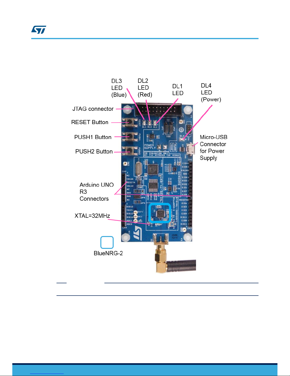
Note: The BlueNRG-2 device on these boards is clocked at 32 MHz XT
AL. These settings are performed in project
configurations.
Figure 1. Connection between the STEV
AL-IDB008V1 or STEV
AL-IDB008V2 and PC
RELATED LINKS
4.1 BlueNRG cold start configuration on page 14
1.4 STEVAL-IDB007V1 BlueNRG1 board setup
To connect the STEV
AL-IDB007V1 (
BlueNRG-1 evaluation board) and PC, one USB port is required to provide
power supply to the board. To connect the ST-Link/V2 debugger, an additional USB port is needed.
Note: Please note that the BlueNRG-1 on this evaluation board is clocked by 16 MHz XTAL. These settings are
performed in project configurations.
UM2295
STEVAL-IDB007V1 BlueNRG1 board setup
UM2295 - Rev 1
page 3/35
Page 4
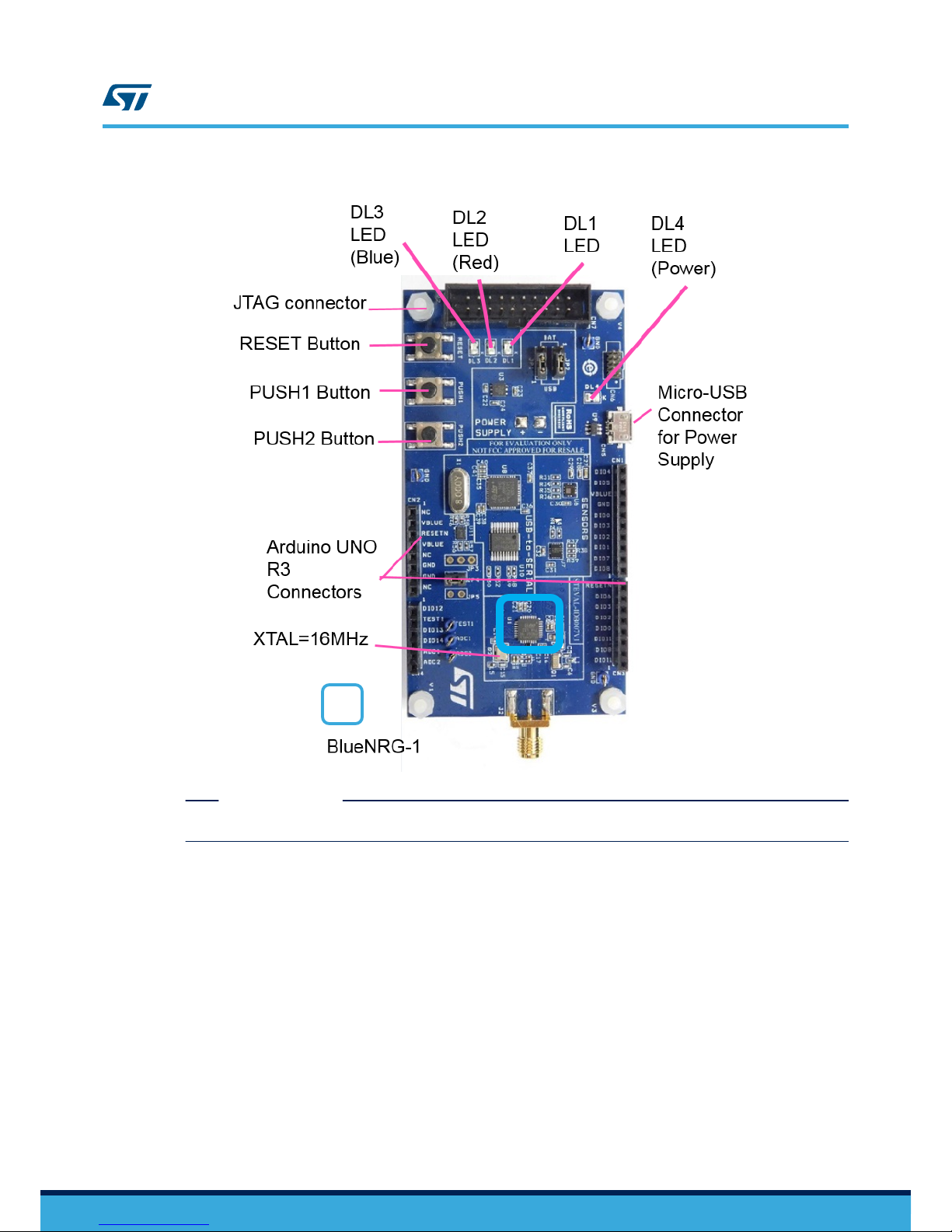
Figure 2. Connection between the STEV
AL-IDB007V1 and PC
RELATED LINKS
4.1 BlueNRG cold start configuration on page 14
1.5 NUCLEO-L152RE plus X-NUCLEO-IDB05A1 board setup
Connect the STM32 NUCLEO-L152RE +
X-NUCLEO-IDB05A1 (BlueNRG-MS board) thanks to a USB cable. The
USB cable is used for two purposes:
1. Providing power supply to the NUCLEO-L152RE + X-NUCLEO-IDB05A1 board
2. Helping in serial communication of data between the PC and the boards NUCLEO-L152RE + X-NUCLEO-
IDB05A1
The STM32 NUCLEO-L152RE board integrates the ST-LINK/V2-1 debugger/ programmer. You can download the
relevant version of the STSW-LINK009 ST-LINK/V2-1 USB driver (according to your version of Windows).
Note: Ensure that BlueNRG-MS is updated with BLE stack version 7.2 c or higher. You can use BlueNRG GUI to
manage the update.
UM2295
NUCLEO-L152RE plus X-NUCLEO-IDB05A1 board setup
UM2295 - Rev 1
page 4/35
Page 5
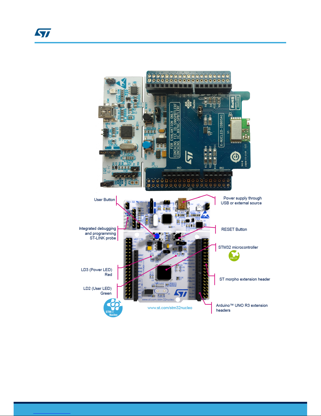
Figure 3. STM32 NUCLEO-L152RE plus X-NUCLEO-IDB05A1 connection with PC
1.6 System requirements
The minimum requirements to set up the software environment and run the BlueNRG-Mesh smart lighting
application are:
• PC with Intel or AMD processor running one of the following Microsoft operating systems: Win XP SP3 Vista/
Windows 7
– At least 128 MB of RAM
–
2 x USB ports
UM2295
System requirements
UM2295 - Rev 1
page 5/35
Page 6

– 40 MB of hard disk space
•
Development toolchains and compilers:
–
Keil µV
ision v5.23
– IAR Embedded Workbench v7.80.4
Please read the system requirements and setup information provided by the IDE provider.
1.7 Installing STSW-BNRG-Mesh
1. Extract the contents of the package in a temporary directory
2.
Launch the installer and follow the on-screen instructions
3. Install in suitable folder in your disk-drive
UM2295
Installing STSW-BNRG-Mesh
UM2295 - Rev 1
page 6/35
Page 7
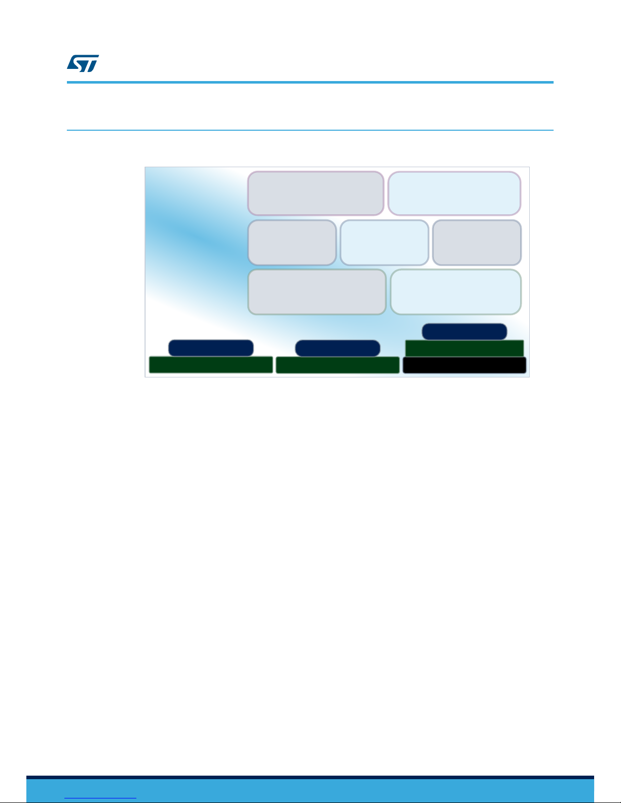
2 Firmware structure
Figure 4. Firmware architecture
Applications
Middleware
Drivers
U t i l i t i e s
C M S I S
Hardware Abstraction
Layer API
LED light demo
Custom applications
Cryptographic
library
BlueNRG-Core
stack
BlueNRG-Mesh
library
Board Support
Packages
NUCLEO-L152RE
X-NUCLEO-IDB05A1
BlueNRG-MS
STEVAL-IDB007V1
STEVAL-IDB008V1/V2
H a r d w a r e
BlueNRG-2
BlueNRG-1
The following folders are included in the package firmware folder:
• A Documentation folder with a compiled HTML file generated from the source code and detailed
documentation of the software components and APIs.
• A Drivers folder with HAL drivers and specific drivers for supported boards, hardware platforms, and
components, and the CMSIS vendor-independent hardware abstraction layer for the Cortex-M processor
series.
•
A Middleware folder with libraries for Mesh and BLE communication.
Horizontal interaction between layer components is handled directly by calling the feature APIs, while
vertical interaction with the low level drivers is managed through specific callbacks and static macros
implemented in the library system call interface.
• A Projects folder contains the workspaces for IAR Embedded Workbench and Keil µVision integrated
development environments for the STEVAL-IDB008V1, STEVAL-IDB007V1 board and NUCLEO-L152RE
plus X-NUCLEO-IDB05A1 board.
The EWARM folder contains the workspace for IAR Embedded Workbench and MDK-ARM folder contains
the workspace for Keil µVision.
The source files in the folder bind the firmware layers to implement the functions that demonstrate Mesh
over BLE functionality.
UM2295
Firmware structure
UM2295 - Rev 1
page 7/35
Page 8
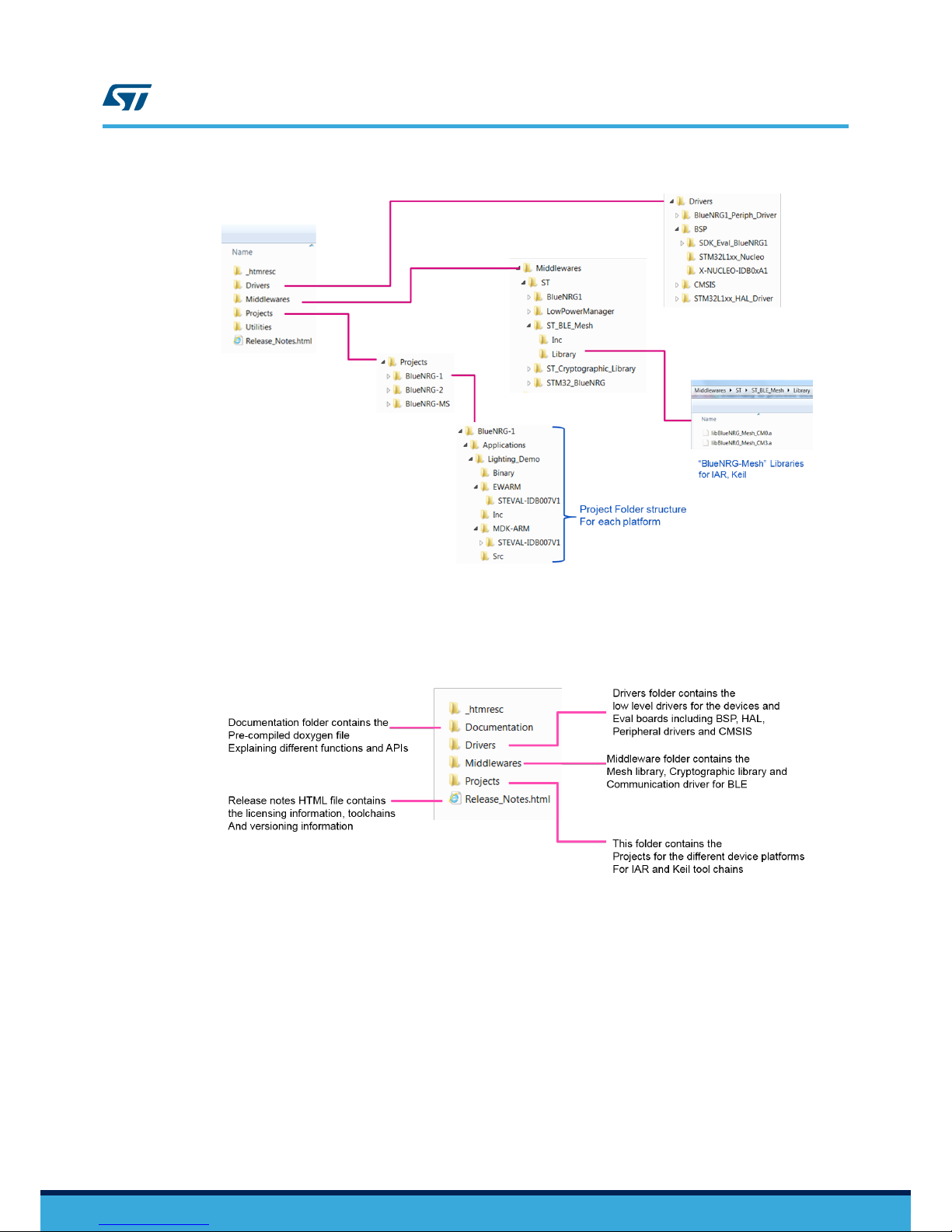
Figure 5. Folders, sub-folders and contents of the package
2.1 Root folder
The figure below shows the root folder structure of the firmware package.
Figure 6. Root folder structure
2.2 Driver folder
This folder contains all low level drivers including peripheral drivers and HAL drivers corresponding to the
hardware.
UM2295
Root folder
UM2295 - Rev 1
page 8/35
Page 9
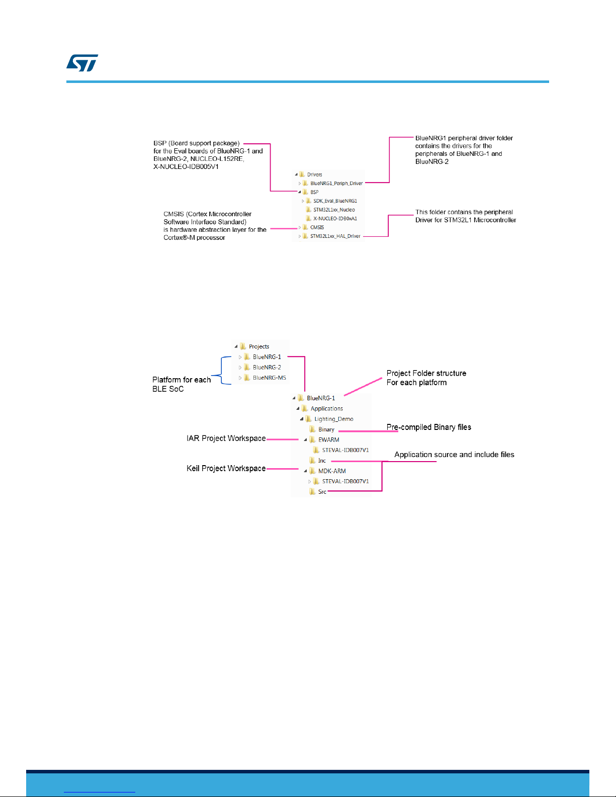
Figure 7. Driver folder
2.3 Project folder
This folder contains the projects for IAR and Keil.
Figure 8. Project folder
2.4 Middleware folder
This folder contains the middleware for the project including pre-compiled Mesh library for the BlueNRG-2,
BlueNRG-1 and BlueNRG-MS + STM32L1.
UM2295
Project folder
UM2295 - Rev 1
page 9/35
Page 10
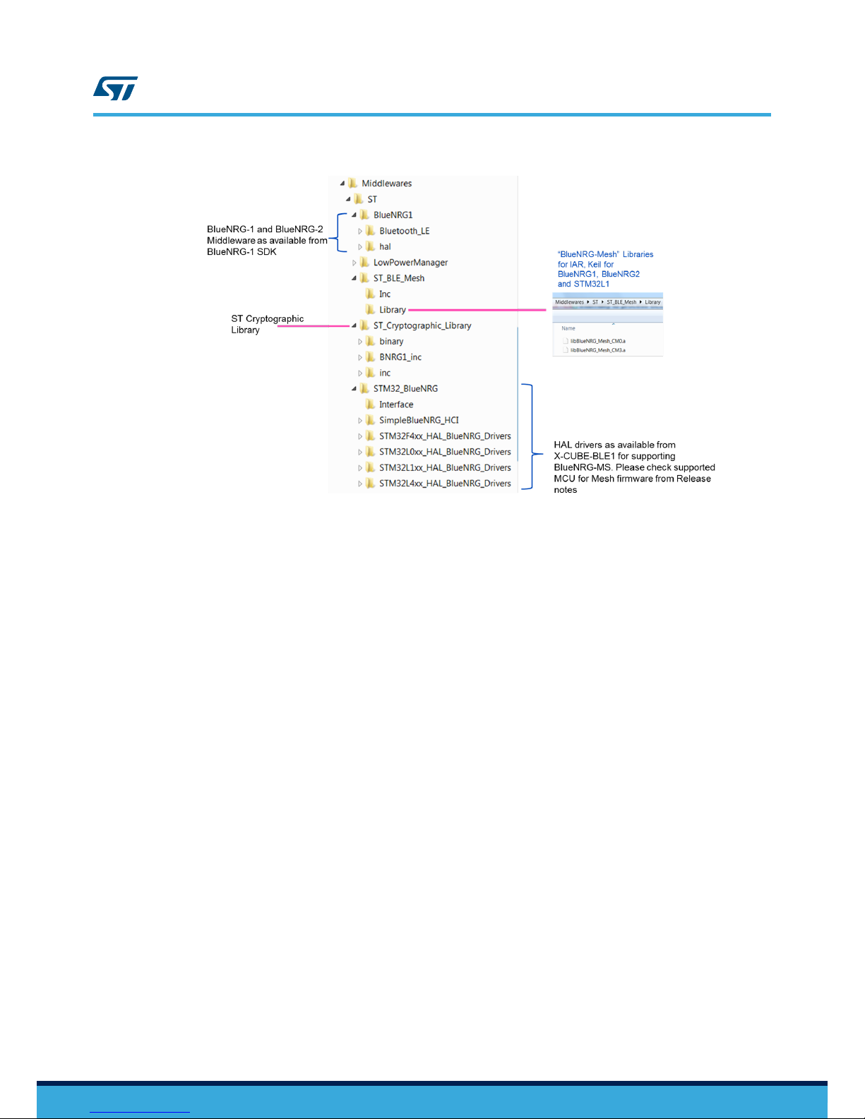
Figure 9. Middleware folder
UM2295
Middleware folder
UM2295 - Rev 1
page 10/35
Page 11
3 Using the BlueNRG-Mesh demo
IAR Embedded Workbench and Keil µVision are used to debug and burn the firmware into the flash memory of
the STEV
AL-IDB008V1, STEV
AL-IDB007V1 and NUCLEO-L152RE+ X-NUCLEO-IDB05A1 boards.
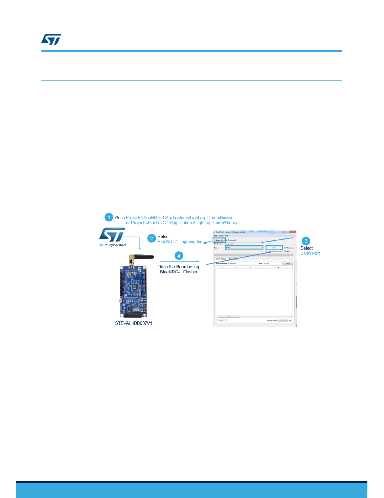
3.1 Using binaries for BlueNRG-1 and BlueNRG-2
1. The pre-compiled binaries are available in Project\<Platform>\Application\<Demo>\Binary folder.
For example for BlueNRG-1, the path is “Projects\BlueNRG-1\Applications\Lighting_Demo\Binary”
2.
These can be programmed in the device using different utilities available for the devices, such as the
BlueNRG-1 Flasher tool or ST-LINK Utility
3. Use "BlueNRG-1 Flasher" tool to program the (STEVAL-IDB007V1 or STEVAL-IDB008V1) boards
connected via micro-USB cable
4. Use "STSW-BNRG1STLINK: BlueNRG-1 ST-LINK utility for BlueNRG-1, BlueNRG-2 MCU” utility to program
boards via ST-LINK
Figure 10. Binaries for BlueNRG-1 and BlueNRG-2
3.2 Using binaries for the STM32L152 used with the BlueNRG-MS
1. The pre-compiled binaries are available in Project\<Platform>\Application\<Demo>\Binary folder
– For example, for
BlueNRG-MS, the path is “Projects\BlueNRG-MS\Applications\Lighting_Demo\Binary
\STM32L152RE-Nucleo”
2. These can be programmed in the device using different utilities
3. Use “ST-LINK Utility” tool to program the boards (NUCLEO-L152RE) connected via mini-USB cable
4. Or, simply drag and drop the .bin file in the drive created by ST-LINK on the STM32 Nucleo board. The
binary will be programmed in the STM32L152 device on the Nucleo board
UM2295
Using the BlueNRG-Mesh demo
UM2295 - Rev 1
page 11/35
Page 12

Figure 11. Overview of how to program the binary in the STM32L152RE MCU
3.3 Using the IAR and Keil projects
Figure 12. Overview
3.3.1 Using IAR project
1. Choose file→open→workspace. Select the project.eww file from the appropriate location. For example, for
the BlueNRG-1, the location is as follows:
–
Embedded\Projects\BlueNRG-1\Applications\Lighting_Demo\EW
ARM\STEVAL-IDB007V1.
2. A project opens in the workspace. This project contains the information regarding your project files and
folders (driver files, application files, middleware, output files, etc.).
3. Build the program with Project→Make Option.
4. Press (download and debug) button to debug the code and flash it to the board.
UM2295
Using the IAR and Keil projects
UM2295 - Rev 1
page 12/35
Page 13

5. Press go button to run the program.
Similarly
, to use the
BlueNRG-MS with boards X-NUCLEO-IDB05A1 and NUCLEO-L152RE, select the
project.eww from: Embedded\Projects\ BlueNRG-MS\Applications\Lighting_Demo\EWARM\STM32L152RENucleo.
3.3.2 Using Keil project
1. Click on File→Open. Select the project.uvprojx file from: Embedded\Projects\BlueNRG-1\Applications
\Lighting_Demo\MDK-ARM\STEVAL-IDB007V1.
2.
To build the program, select Project→Build Target or simply click on the Build Target icon.
To debug the program, select Debug→Start/Stop Debug Session or click on the Start/Stop Debug Session icon.
To flash the program to the flash memory on the board click on the icon.
UM2295
Using the IAR and Keil projects
UM2295 - Rev 1
page 13/35
Page 14

4 Firmware initialization and configuration
This section describes the available function APIs for application development based on Mesh network over
Bluetooth Low Energy devices.
The Mesh over BLE library manages the following features:
•
Creates the Mesh network between nodes
•
Handles the unicast, broadcast addressing
• Manages the relay feature: all the packets whose destination address is for another node are re-transmitted
• Communication with devices for advanced features, such as provisioning and proxy service
• Handles the platform specific communication
The user application handles the following
• Initialization of the Mesh stack
• User callbacks required for the application
• Application handling
The following sections describe the requirements for initialization and configuration of the firmware.
4.1 BlueNRG cold start configuration
Concerning the BlueNRG-1 and BlueNRG-2
devices, certain parameters must be defined on BLE device
controller registers during the device initialization phase, after the device powers on:
•
High speed crystal configuration: 32 or 16 MHz
• Low speed crystal source: external 32 kHz oscillator or internal RO
• SMPS: on or off (if on: 4.7 μH or 10 μH SMPS inductor)
The BlueNRG-1, BlueNRG-2 controllers are configured in the project C/C++ Preprocessor settings.
For example:
• for IAR, go to Project → Options → C/C++ Compiler → Preprocessor → Defined Symbols
• For Keil, go to Project → Options → C/C++ → Preprocessor Symbols → Define
The following symbols are used in the project: USER_DEFINED_PLATFORM=STEVAL_IDB007V1:
• HS_SPEED_XTAL=HS_SPEED_XTAL_16MHZ
• LS_SOURCE=LS_SOURCE_EXTERNAL_32KHZ
• SMPS_INDUCTOR=SMPS_INDUCTOR_10 uH.
These can be changed to suit your hardware design.
RELATED LINKS
1.3 STEVAL-IDB008V1 or STEVAL-IDB008V2 BlueNRG2 board setup on page 2
1.4 STEVAL-IDB007V1 BlueNRG1 board setup
on page 3
4.2 Setting the transmit power of a node
You can define the transmit power of a node by initializing a callback to the Mesh library. It runs in the following
manner:
{
Appli_BleStackInitCb,
Appli_BleSetTxPowerCb,
Appli_BleGattConnectionCompleteCb,
Appli_BleGattDisconnectionCompleteCb,
Appli_BleUnprovisionedIdentifyCb,
UM2295
Firmware initialization and configuration
UM2295 - Rev 1
page 14/35
Page 15

Appli_BleSetUUIDCb,
};
The Appli_BleSetTxPowerCb() calls the aci function to set the power aci_hal_set_tx_power_level(ui
nt8_t En_High_Power, uint8_t PA_Level);
By default, +4 dbm is configured in the nodes for BlueNRG-1 and BlueNRG-2; this can be changed by the user.
For
BlueNRG-1 and BlueNRG-2, the following different settings are available in the firmware:
/* MACROS for Power Level definitions */
#define POWER_LEVEL_LOW 0
#define TX_POWER_LEVEL_MINUS_18DBM 0 // = -18 dBm,
#define TX_POWER_LEVEL_MINUS_15DBM 1 // = -15 dBm,
#define TX_POWER_LEVEL_MINUS_12DBM 2 // = -12 dBm,
#define TX_POWER_LEVEL_MINUS_9DBM 3 // = -9 dBm,
#define TX_POWER_LEVEL_MINUS_6DBM 4 // = -6 dBm,
#define TX_POWER_LEVEL_MINUS_2DBM 5 // = -2 dBm,
#define TX_POWER_LEVEL_0DBM 6 // = 0 dBm,
#define TX_POWER_LEVEL_PLUS_5DBM 7 // = 5 dBm.
#define POWER_LEVEL_HIGH 1
#define TX_POWER_LEVEL_MINUS_14DBM 0 // = -14 dBm,
#define TX_POWER_LEVEL_MINUS_11DBM 1 // = -11 dBm,
#define TX_POWER_LEVEL_MINUS_8DBM 2 // = -8 dBm,
#define TX_POWER_LEVEL_MINUS_5DBM 3 // = -5 dBm,
#define TX_POWER_LEVEL_PLUS_2DBM 5 // = 2 dBm,
#define TX_POWER_LEVEL_PLUS_4DBM 6 // = 4 dBm,
#define TX_POWER_LEVEL_PLUS_8DBM 7 // = 8 dBm
4.3 UART interface on the firmware
The boards can be connected to a PC via USB connection. Any terminal software (HyperTerminal, Hercules,
Putty, etc.) can be used to open the serial communication port on the PC to check the messages from the board.
The UAR
T of the controller on the board is connected to the PC via a VCOM (virtual communication) port. The
settings to open the communication port are:
• Baud: 115200
• data size: 8
• parity: none
• stop bits: 1
• no hardware control
From the firmware main.c file, it can be seen that certain messages are printed to the VCOM
#if !defined(DISABLE_TRACES)
printf("BlueNRG-Mesh lighting demo v%s\n\r", MOBLE_VERSION);
printf("MAC Address = [%02x]:[%02x]:[%02x]:[%02x]:[%02x]:[%02x]
\n\r",bdaddr[5],bdaddr[4],bdaddr[3],bdaddr[2],bdaddr[1],bdaddr[0] );
#endif
After the board is connected and the terminal window is opened, press the reset button. If the firmware starts
successfully, the following messages are printed to the virtual com window
UM2295
UART interface on the firmware
UM2295 - Rev 1
page 15/35
Page 16

Figure 13. VCOM window
In some evaluation boards, an error can be received. In this case, MAC address management section of the
document helps to meet this issue. Examples of bad MAC address are provided below
Figure 14. Bad MAC address
4.4 MAC address management
MAC address is required to be unique in each node for the Mesh network. The following options are available to
configure the MAC addresses of the node
Table 3.
MAC address management
Number MAC address
management
Comments
1 Using external MAC
address
User can program the nodes with desired unique MAC address. This is stored at specific
location in the flash. It is user’
s responsibility to make sure that the MAC address
programmed in the device is compliant to the requirements of the Bluetooth
communication.
To configure this, define the following macro in the project pre-processor.
EXTERNAL_MAC_ADDR_MGMT
2 Using unique serial
number of the device
It is possible to configure the MAC address of the device using the unique serial number
available in each device.
This is the default setting.
4.5 Button usage
Features
BlueNRG-1 and BlueNRG-2 (STEVAL-IDB007V1
and STEV
AL-IDB008V1)
BlueNRG-MS (X-NUCLEO-IDB05A1 + NUCLEOL152RE)
Buttons LEDs Buttons LEDs
Mesh Lib error DL3 Blinks continuously LD2 Blinks continuously
Mesh Lib
library
successful
start
2 Blinks on DL3 NO Blinks
Provisioning DL3 Blinks for few times DL3 Blinks for few times
UM2295
MAC address management
UM2295 - Rev 1
page 16/35
Page 17

Features
BlueNRG-1 and BlueNRG-2 (STEVAL-IDB007V1
and STEVAL-IDB008V1)
BlueNRG-MS (X-NUCLEO-IDB05A1 + NUCLEOL152RE)
Buttons LEDs Buttons LEDs
UnProvisioning
1. RESET + PUSH1
button pressed
2.
Release RESET
button
3.
Long press of
PUSH1 button
causes unprovisioning
4. Reset the board
1. DL3 blinks and then
keeps glowing
during unprovisioning
1. RESET + USER
button pressed
2.
Release RESET
button
3. Long press USER
button causes unprovisioning
4. Reset the board
LD2 Blinks and then
keeps glowing during unprovisioning
Running the
demo from
board
1. Press PUSH1
button on any board
2.
It will send the
command on
Publication Address
1.
DL3 on the board
toggles (If
Subscribed for the
Published Address)
2. DL3 on other boards
(if subscribed for the
Published address)
will also toggle
1. Press USER
button on any
board
2. It will send the
command on
Publication
Address
1. LD2 on the board
toggles (If
Subscribed for the
Published Address)
2. LD2 on other
boards (if
subscribed for the
Published address)
will also toggle
OTA
(1)
1. Long Press PUSH2
2.
RESET the Board
1.
ONL
Y on BlueNRG-2
4.6 Initialization of application callbacks
The configuration of the application starts by initializing the callbacks required for the different events and
functionalities. These callbacks are used in the BlueNRG-Mesh library to call the functions based on specific
events or the library state machine.
{
Appli_LedBlinkCb,
Appli_LedStateCtrlCb,
Appli_WriteLocalDataCb,
Appli_ReadLocalDataCb
};
/* Callbacks used by BlueNRG-Mesh library */
BluenrgMesh_SetVendorCbMap(&vendor_cb);
The structure MOBLE_VENDOR_CB_MAP is used to initialize the vendor model for the application
implementation. The function BluenrgMesh_SetVendorCbMap(&vendor_cb);is used to initialize the different
callbacks in the library
.
4.7 Initialization and main application loop
This procedure develops an application for Mesh over BLE on the BlueNRG platforms.
The following steps are for the BlueNRG-2 and BlueNRG-1 platforms. The procedure is similar for the BlueNRG-
MS platform, but with a few minor differences.
Step 1. Call the
InitDevice() API.
This in turn calls the SystemInit() API to initialize the BlueNRG-1 device vector table, interrupt
priorities and clock. The initialization is run similarly for the BlueNRG-MS platform.
Step 2. Call the Appli_CheckBdMacAddr() API to check the validity of the MAC address.
UM2295
Initialization of application callbacks
UM2295 - Rev 1
page 17/35
Page 18

If the MAC address is not valid, then the firmware is stuck in while(1) loop with LED blinking
continuously
.
Step 3. Initialize the hardware callback functions for the BLE hardware.
Y
ou do this by updating MOBLE_USER_BLE_CB_MAP user_ble_cb =
{
Appli_BleStackInitCb,
Appli_BleSetTxPowerCb,
Appli_BleGattConnectionCompleteCb,
Appli_BleGattDisconnectionCompleteCb,
Appli_BleUnprovisionedIdentifyCb,
Appli_BleSetUUIDCb,
};
Step 4. These APIs are useful to have an application interface for BLE radio initialization and TxPower
configuration.
–
Initialize GA
TT connection and disconnection callbacks for the application interface.
– BluenrgMesh_BleHardwareInitCallBack(&user_ble_cb) can be called to complete the
initialization of hardware callbacks.
Step 5. Initialize the BlueNRG-Mesh library by calling BluenrgMesh_Init(bdaddr).
In the event of an error, the demo firmware prints a message on the terminal window opened for the
VCOM port created by the USB connection available on the boards, and the Appli_LedBlinkCb()
API causes the LED to blink continuously.
Step 6. Check whether the device has been provisioned or not. A provisioned device has network keys and
other parameters configured in the internal flash memory.
Checks can be performed with BluenrgMesh_IsUnprovisioned() API.
If the Node is unprovisioned, BluenrgMesh_InitUnprovisionedNode() API initializes it.
If the device is already provisioned , then BluenrgMesh_InitprovisionedNode() API helps to
initialize the device.
Step 7. Print the messages to the terminal window for the nodes that are being initialised.
The message also prints the MAC address assigned to the node.
Step 8. Check the button state. To initialize the node to the unprovisioned state, hold down the user button.
When the unprovisioning button sequence is detected, the BluenrgMesh_Unprovision() API
erases all the network parameters configured in the internal memory of the device.
Once unprovisioning is complete, you need to reset the board.
Step 9. Initialize the vendor model callback functions that are triggered by the events.
BluenrgMesh_SetVendorCbMap(&vendor_cb);
Step 10. Process MoBLE and HCI events in while(1) loop.
The application must call BluenrgMesh_Process() in while(1) loop as frequently as possible.
This function calls BLE_StackTick() internally to process BLE communication.
Any application implementation shall be performed in the state-machine by non-blocking functions with
frequent calls to
BluenrgMesh_Process().
Step 11. Check for user-inputs or buttons regularly for any action to take.
UM2295
Initialization and main application loop
UM2295 - Rev 1
page 18/35
Page 19

5 Mesh networking information
5.1 Local and remote concept
Remote actions or operations refer to other nodes in the network, while local actions refer to the resources on the
same node in the network.
For example, if you want to control the LEDs of nodes on the BlueNRG-Mesh app, click the icon button to invoke
the _SetRemoteData action from the app. This causes a _WriteLocalDataCb action on the node.
This is also the case when you wants to control the LEDs of the nodes of a group from the board. The LEDs on
the nodes subscribed to the Publish address will toggle when the button on the board is pressed.
The same message received on the node which needs to turn on the LEDs requires a WriteLocal action on
that node. This is shown in the figure below for the SetRemote/WriteLocal
actions on dif
ferent nodes in the
network.
Figure 15. SetRemote/WriteLocal actions
SetRemoteData
ReadLocalData
Mesh LibraryMesh Library
Source
Destination
LED ON
User-Action to
switch on remote
node lights
Appli_ReadLocalDataCb
5.2 Acknowledged and unacknowledged messages
By default, all messages in the Mesh network are configured as unacknowledged. The difference between
acknowledged and unacknowledged messages is the response to the message. For example, a write message to
a node may have a response in acknowledged communication. Whereas, in unacknowledged communication, the
response may not be there.
Y
ou should use unacknowledged messages in the mesh network to avoid the exchange of multiple messages in
the network, which may take time to the process.
5.3 Provisioning process
The process of configuring a devices in a network is called provisioning. The process is started by a “Provisioner”,
which is a BlueNRG-Mesh app running on the smartphone.
UM2295
Mesh networking information
UM2295 - Rev 1
page 19/35
Page 20

Figure 16. Provisioning process
Unconfigured
mesh node
Configured
mesh node
Unprovisioned
device
Provisioning with data: network key, Key index
Flags, IV index, unicast address
Unprovisioning
Configuration information
The BlueNRG-Mesh app can be installed on the smartphone with BLE 4.0 or higher. During installation, the app
asks for some user permissions, refer to the appropriate BlueNRG-Mesh user manual for your device type
(Android or iOS) on www.st.com . The steps required for the provisioning are shown in the figure below.
UM2295
Provisioning process
UM2295 - Rev 1
page 20/35
Page 21

Figure 17. Provisioning steps
The provisioning is executed by GATT connection between the smartphone and the unprovisioned device.
RELATED LINKS
5.4 GATT connection/disconnection node on page 21
5.4 GATT connection/disconnection node
Each node in the network has the capability to make connection with the smartphone through GATT interface.
When this connection is established, the node becomes a “proxy”. The proxy has the responsibility to bridge the
commands and response between the Mesh network and the smartphone. The detection of connection and
disconnection with smartphone is managed by the following callbacks
Appli_BleGattConnectionCompleteCb;
Appli_BleGattDisconnectionCompleteCb;
These are initialized during the main loop. It can be interesting sometimes to know which node is connected to the
smartphone when there are many nodes nearby.
During provisioning, the GA
TT connection is established with the node which needs to be provisioned. It may be
noted that if the smartphone moves out of the range of the proxy node, it establishes a new connection with the
node which is available. For example: in the example project, for BlueNRG-1 and BlueNRG-2, a LED indication
(LED2) is used to show the proxy connection.
RELATED LINKS
5.3 Provisioning process on page 19
UM2295
GATT connection/disconnection node
UM2295 - Rev 1
page 21/35
Page 22

5.5 Write command from remote node
A command from a remote node or from a smartphone to an addressed node invokes a WriteLocalData
callback.
This callback can be used to process the commands or data received inside the network. In the application demo,
the Appli_WriteLocalDataCb
function is the callback where data or commands will be processed. The
command/data flow can be visualised in the picture below
.
Figure 18. Write command data flow
SetRemoteData
User-Action to
switch remote
node lights
on
WriteLocalData
Mesh LibraryMesh Library
Source
Destination
LED ON
Appli_WriteLocalDataCb
The response data from the node is sent through SendResponse function.
5.6 Read command from a remote node
A Read command from a remote node or from a smartphone to an addressed node to get some information,
invokes the ReadLocalData
callback. This callback can be used to read some information that a remote node
asks and provides the data back to the remote node. In the application demo, the Appli_ReadLocalDataCb
function is the callback where the read commands is processed. The command/data flow can be seen in the
picture below
.
Figure 19. Read command from a remote node
ReadRemoteData()
User-Action to
R
ead
a remote
node information
ReadLocalData
ReadAction
Appli_ReadLocalDataCb
Mesh LibraryMesh Library
Source
Destination
SendResponse
Sensor
ResponseCb
The response data from the node is sent via the SendResponse function.
5.7 Application functions and callbacks
The following section explains the different APIs available for the user application.
UM2295
Write command from remote node
UM2295 - Rev 1
page 22/35
Page 23

5.7.1 User interface and indications
Table 4. Appli_LedBlinkCb
Function Description
Prototype MOBLE_RESULT Appli_LedBlinkCb(void)
Behaviour description It blinks the on-board LED. This function is used at power-on
and at the error conditions due to user's attention
Input parameter None
Output parameter MOBLE_RESULT status of result
Table 5. Appli_LedStateCtrlCb
Function Description
Prototype MOBLE_RESULT Appli_LedStateCtrlCb(MOBLEUINT16 ctrl)
Behaviour description Sets the state of the LEDs or Lighting interface connected
Input parameter MOBLEUINT16 ctrl: sets the state of LEDs
Output parameter MOBLE_RESULT status of result
5.7.2 User and button interface
Table 6. Appli_ShortButtonPress
Function API parameters Description
Prototype Static void Appli_ShortButtonPress(void)
Behaviour description Function calls when a button is pressed for short duration
Input parameter Void
Output parameter Void
Table 7. Appli_LongButtonPress
Function Description
Prototype Static void Appli_LongButtonPress(void)
Behaviour description Function calls when a button is pressed for long duration
Input parameter Void
Output parameter Void
Table 8. Appli_UpdateButtonState
Function Description
Prototype Void Appli_UpdateButtonState(int isPressed)
Behaviour description Updates the button status
Input parameter int isPressed
Output parameter Void
UM2295
Application functions and callbacks
UM2295 - Rev 1
page 23/35
Page 24

5.7.3 Device BLE configuration type interface
This section explains the functions available to the application developer to configure the device to be used in the
network.
T
able 9.
Appli_BleStackInitCb
Function Description
Prototype MOBLE_RESULT Appli_BleStackInitCb()
Behaviour description This function helps with hardware configuration; mainly the
initialization of the BLE Stack based on the structured
parameters defined in BlueNRG_Stack_Init_params.
The user can modify the Low level hardware configuration
data for the device defined in CONFIG_T
ABLE like
LOW_SPEED_SOURCE and HS_ST
ARTUP_TIME, which
may depend on the user hardware design.
The Parameters initializes BlueNRG Stack
Input parameter None
Output parameter MOBLE_RESULT status of result
Table 10. Appli_SetTxPowerCb
Function Description
Prototype MOBLE_RESULT Appli_BleSetTxPowerCb()
Behaviour description This callback sets the transmission power of BLE radio. IN
turns this function call aci_hal_set_tx_power_level. By default,
the power level is set to -2 dbm
Input parameter None
Output parameter MOBLE_RESULT status of result
Table 11. Appli_BleGattConnectionCompleteCb
Function Description
Prototype void Appli_BleGattConnectionCompleteCb(void)
Behaviour description This function is called when GATT Connection is detected by
the node. The application can use this callback to indicate to
the user that node is connected to the smartphone
Input parameter Void
Output parameter Void
Table 12. Appli_BleGattDisconnectionCompleteCb
Function Description
Prototype void Appli_BleGattDisconnectionCompleteCb(void)
Behaviour description This function is called when GATTDisconnection is detected
by the node. The application can use this callback to indicate
to the user that node is no longer connected to the
smartphone
Input parameter None
UM2295
Application functions and callbacks
UM2295 - Rev 1
page 24/35
Page 25

Function Description
Output parameter None
5.7.4 Network data communication functions
The functions explained below help the developer to manage the network data communication and take the
associated actions.
Table 13. Appli_W
riteLocalDataCb
Function Description
Prototype MOBLE_RESULT
Appli_WriteLocalDataCb(MOBLE_ADDRESS peer_addr
,
MOBLE_ADDRESS dst_peer,
MOBLEUINT8 command,
MOBLEUINT8 const *data,
MOBLEUINT32 length,
MOBLEBOOL response)
Behaviour description Call back function called when action is required on node
itself
Input parameters MOBLE_ADDRESS peer_addr: address of the peer
MOBLE_ADDRESS dst_peer: destination address of the
command. This address can be the address of Group to
which the node is subscribed or the unicast address of
element
MOBLEUINT16 command: command received for the action
MOBLEUINT8 const *data pointer to the data
MOBLEUINT32 length: length of the data
MOBLEBOOL response: If this is MOBLE_TRUE, the sender
expects an acknowledgement
Output parameter MOBLE_RESULT status of result
Table 14. Appli_ReadLocalDataCb
Function Description
Prototype MOBLE_RESULT
Appli_ReadLocalDataCb(MOBLE_ADDRESS peer_addr,
MOBLE_ADDRESS dst_peer
,
MOBLEUINT8 command,
MOBLEUINT8 const *data,
MOBLEUINT32 length,
MOBLEBOOL response)
Behaviour description Callback function invoked when some data are required from
node
UM2295
Application functions and callbacks
UM2295 - Rev 1
page 25/35
Page 26

Function Description
Input parameter MOBLE_ADDRESS peer_addr: address of the peer
MOBLE_ADDRESS dst_peer: destination address of the
command. This address can be the address of Group to
which the node is subscribed or the unicast address of
element
MOBLEUINT16 command : command received for processing
MOBLEUINT8 const *data pointer to the data
MOBLEUINT32 length: length of the data
MOBLEBOOL response: If this is MOBLE_TRUE, the sender
expects an acknowledgement
Output parameter MOBLE_RESULT status of result
5.7.5 MAC address configuration
Table 15. Appli_CheckBdMacAddr
Function Description
Prototype int Appli_CheckBdMacAddr(void)
Behaviour description Checks MAC address validity
Input parameter Void
Output parameter MOBLEUINT8 sum return the sum calculated MAC
Table 16. Appli_GetMACfromUniqueNumber
Function Description
Prototype #ifndef EXTERNAL_MAC_ADDR_MGMT
static void Appli_GetMACfromUniqueNumber(void)
Behaviour description Reads the unique serial number of the device and generates
the MAC address from it
Input parameter Void
Output parameter Void
UM2295
Application functions and callbacks
UM2295 - Rev 1
page 26/35
Page 27

A References
Table 17.
References
Name Title/description
Bluetooth specifications Specification of the Bluetooth system (v4.0, v4.1, v4.2, v5.0)
Bluetooth specifications Mesh profile specifications v1.0
UM2295
References
UM2295 - Rev 1
page 27/35
Page 28

B Licensing and other information
• Developer-friendly license terms
•
Initial BlueNRG-Mesh is built over Motorola’s Mesh Over Bluetooth Low Energy (MoBLE) technology. The
present solution is developed and maintained for both Mesh library and Applications solely by
STMicroelectronics.
UM2295
Licensing and other information
UM2295 - Rev 1
page 28/35
Page 29

Revision history
Table 18.
Document revision history
Date Revision Changes
09-Feb-2018 1 Initial release
UM2295
UM2295 - Rev 1
page 29/35
Page 30

Contents
1 Getting started.....................................................................2
1.1 Hardware requirements .........................................................2
1.2 Board interfaces ...............................................................2
1.3 STEVAL-IDB008V1 or STEV
AL-IDB008V2 BlueNRG2 board setup ....................2
1.4 STEVAL-IDB007V1 BlueNRG1 board setup........................................3
1.5 NUCLEO-L152RE plus X-NUCLEO-IDB05A1 board setup ...........................4
1.6 System requirements...........................................................5
1.7 Installing STSW-BNRG-Mesh....................................................6
2 Firmware structure ................................................................7
2.1 Root folder ...................................................................8
2.2 Driver folder ..................................................................8
2.3 Project folder..................................................................9
2.4 Middleware folder ..............................................................9
3 Using the BlueNRG-Mesh demo ...................................................11
3.1 Using binaries for BlueNRG-1 and BlueNRG-2 ....................................11
3.2 Using binaries for the STM32L152 used with the BlueNRG-MS ......................11
3.3 Using the IAR and Keil projects .................................................12
3.3.1 Using IAR project .......................................................12
3.3.2 Using Keil project .......................................................13
4 Firmware initialization and configuration ..........................................14
4.1 BlueNRG cold start configuration ................................................14
4.2 Setting the transmit power of a node .............................................14
4.3 UART interface on the firmware .................................................15
4.4 MAC address management ....................................................16
4.5 Button usage.................................................................16
4.6 Initialization of application callbacks .............................................17
4.7 Initialization and main application loop ...........................................17
5 Mesh networking information .....................................................19
5.1 Local and remote concept ......................................................19
UM2295
Contents
UM2295 - Rev 1
page 30/35
Page 31

5.2 Acknowledged and unacknowledged messages ...................................19
5.3 Provisioning process ..........................................................19
5.4 GATT connection/disconnection node............................................21
5.5 W
rite command from remote node...............................................21
5.6 Read command from a remote node .............................................22
5.7 Application functions and callbacks ..............................................22
5.7.1 User interface and indications .............................................22
5.7.2 User and button interface .................................................23
5.7.3 Device BLE configuration type interface ......................................23
5.7.4 Network data communication functions ......................................25
5.7.5 MAC address configuration ...............................................26
A References .......................................................................27
B Licensing and other information ..................................................28
Revision history .......................................................................29
Contents ..............................................................................30
List of figures..........................................................................32
List of tables ..........................................................................33
Acronyms and abbreviations ..........................................................34
UM2295
Contents
UM2295 - Rev 1
page 31/35
Page 32

List of figures
Figure 1. Connection between the STEVAL-IDB008V1 or STEV
AL-IDB008V2 and PC .........................3
Figure 2. Connection between the STEVAL-IDB007V1 and PC .........................................4
Figure 3. STM32 NUCLEO-L152RE plus X-NUCLEO-IDB05A1 connection with PC ...........................5
Figure 4. Firmware architecture ...............................................................7
Figure 5. Folders, sub-folders and contents of the package ............................................8
Figure 6. Root folder structure ................................................................8
Figure 7. Driver folder ......................................................................9
Figure 8. Project folder .....................................................................9
Figure 9. Middleware folder ................................................................. 10
Figure 10. Binaries for BlueNRG-1 and BlueNRG-2 ................................................. 11
Figure 11. Overview of how to program the binary in the STM32L152RE MCU .............................. 12
Figure 12. Overview .......................................................................12
Figure 13. VCOM window ................................................................... 16
Figure 14. Bad MAC address................................................................. 16
Figure 15. SetRemote/WriteLocal actions ........................................................ 19
Figure 16. Provisioning process ...............................................................20
Figure 17. Provisioning steps................................................................. 21
Figure 18. Write command data flow............................................................ 22
Figure 19. Read command from a remote node .................................................... 22
UM2295
List of figures
UM2295 - Rev 1
page 32/35
Page 33

List of tables
Table 1. Hardware requirements ...............................................................
2
Table 2. Evaluation board details ...............................................................2
Table 3. MAC address management ............................................................ 16
Table 4. Appli_LedBlinkCb .................................................................. 23
Table 5. Appli_LedStateCtrlCb ................................................................ 23
Table 6. Appli_ShortButtonPress .............................................................. 23
Table 7. Appli_LongButtonPress .............................................................. 23
Table 8. Appli_UpdateButtonState ............................................................. 23
Table 9. Appli_BleStackInitCb ................................................................ 24
Table 10. Appli_SetTxPowerCb ................................................................ 24
Table 11. Appli_BleGattConnectionCompleteCb .................................................... 24
Table 12. Appli_BleGattDisconnectionCompleteCb .................................................. 24
Table 13. Appli_WriteLocalDataCb .............................................................. 25
Table 14. Appli_ReadLocalDataCb.............................................................. 25
Table 15. Appli_CheckBdMacAddr ..............................................................26
Table 16. Appli_GetMACfromUniqueNumber ....................................................... 26
Table 17. References ....................................................................... 27
Table 18. Document revision history ............................................................. 29
Table 19. Acronyms and abbreviations ........................................................... 34
UM2295
List of tables
UM2295 - Rev 1
page 33/35
Page 34

Acronyms and abbreviations
T
able 19.
Acronyms and abbreviations
Acronym Description
API Application programming interface
BLE Bluetooth Low Energy
BSP Board support package
DFU Device firmware upgrade
GUI Graphical user interface
HAL Hardware abstraction layer
HW Hardware
IDE Integrated development environment
LED Light emitting diode
MCU Microcontroller unit
MoBLE Mesh over Bluetooth Low Energy
SoC System-on-chip
USB Universal serial bus
UM2295
UM2295 - Rev 1
page 34/35
Page 35

IMPORTANT NOTICE – PLEASE READ CAREFULLY
STMicroelectronics NV and its subsidiaries (“ST”) reserve the right to make changes, corrections, enhancements, modifications, and improvements to ST
products and/or to this document at any time without notice. Purchasers should obtain the latest relevant information on ST products before placing orders. ST
products are sold pursuant to ST’s terms and conditions of sale in place at the time of order acknowledgement.
Purchasers are solely responsible for the choice, selection, and use of ST products and ST assumes no liability for application assistance or the design of
Purchasers’ products.
No license, express or implied, to any intellectual property right is granted by ST herein.
Resale of ST products with provisions dif
ferent from the information set forth herein shall void any warranty granted by ST for such product.
ST and the ST logo are trademarks of ST. All other product or service names are the property of their respective owners.
Information in this document supersedes and replaces information previously supplied in any prior versions of this document.
© 2018 STMicroelectronics – All rights reserved
UM2295
UM2295 - Rev 1
page 35/35
 Loading...