

Page 1

UM2269
User manual
Getting started with PowerShield firmware
Introduction
The STM32-LPM01-XN is an STMicroelectronics energy meter firmware dedicated to power
consumption measurements for microcontrollers and boards.
It runs on X-NUCLEO-LPM01A and STM32L562E-DK boards.
In this document the firmware and its associated boards are referred to as “PowerShield”.
PowerShield is a a plug-and-play solution intended to ease power consumption
measurements, used to supply and measure current consumption of boards such as STM32
Nucleo and Arduino
This document guides the user through the firmware characteristics and specific use cases.
This document must be read in conjunction with the following documents, available on
www.st.com:
• User manuals of boards:
– STM32 Nucleo expansion board for power consumption measurement (UM2243) for
standalone board X-NUCLEO-LPM01A
– Discovery board with STM32L562E MCU (UM2617) for STM32L5 discovery kit,
• User manuals of software tool:
– STM32CubeMonitor-Power software tool for power and ultra-low-power
measurements (UM2202).
®
.
October 2020 UM2269 Rev 6 1/59
www.st.com
1
Page 2

Contents UM2269
Contents
1 Boards overview . . . . . . . . . . . . . . . . . . . . . . . . . . . . . . . . . . . . . . . . . . . . 7
1.1 PowerShield standalone board X-NUCLEO-LPM01A . . . . . . . . . . . . . . . . 7
1.2 Quick setup to measure current on board Nucleo64 with
standalone board X-NUCLEO-LPM01A . . . . . . . . . . . . . . . . . . . . . . . . . . . 9
1.3 STM32L5 discovery board STM32L562E-DK . . . . . . . . . . . . . . . . . . . . . . 9
2 PowerShield modes and requirements . . . . . . . . . . . . . . . . . . . . . . . . . 11
2.1 Standalone mode . . . . . . . . . . . . . . . . . . . . . . . . . . . . . . . . . . . . . . . . . . . .11
2.2 Controlled by host mode with commands sent by a COM
port terminal . . . . . . . . . . . . . . . . . . . . . . . . . . . . . . . . . . . . . . . . . . . . . . . 12
2.3 Controlled by host mode with commands sent by a GUI . . . . . . . . . . . . . 12
3 PowerShield standalone mode . . . . . . . . . . . . . . . . . . . . . . . . . . . . . . . 14
4 PowerShield controlled by host mode . . . . . . . . . . . . . . . . . . . . . . . . . 19
4.1 Serial COM port configuration . . . . . . . . . . . . . . . . . . . . . . . . . . . . . . . . . 19
4.2 PowerShield shell . . . . . . . . . . . . . . . . . . . . . . . . . . . . . . . . . . . . . . . . . . . 20
4.2.1 Transfer protocol of commands . . . . . . . . . . . . . . . . . . . . . . . . . . . . . . . 20
4.2.2 Transfer protocol of measurement data stream . . . . . . . . . . . . . . . . . . . 21
4.2.3 Command management . . . . . . . . . . . . . . . . . . . . . . . . . . . . . . . . . . . . 21
4.3 Interface commands . . . . . . . . . . . . . . . . . . . . . . . . . . . . . . . . . . . . . . . . . 21
4.3.1 Command list summary . . . . . . . . . . . . . . . . . . . . . . . . . . . . . . . . . . . . . 21
4.3.2 Command description . . . . . . . . . . . . . . . . . . . . . . . . . . . . . . . . . . . . . . 25
4.4 Data stream format . . . . . . . . . . . . . . . . . . . . . . . . . . . . . . . . . . . . . . . . . . 31
4.4.1 Data format 1: ASCII, decimal basis . . . . . . . . . . . . . . . . . . . . . . . . . . . 31
4.4.2 Data format 2: Binary, hexadecimal basis . . . . . . . . . . . . . . . . . . . . . . . 36
4.5 Examples of typical use cases . . . . . . . . . . . . . . . . . . . . . . . . . . . . . . . . . 43
4.5.1 Minimal mandatory commands . . . . . . . . . . . . . . . . . . . . . . . . . . . . . . . 43
4.5.2 Continuous measurement (infinite samples) with target reset
during acquisition . . . . . . . . . . . . . . . . . . . . . . . . . . . . . . . . . . . . . . . . . . 44
4.5.3 Two single measurements of 100 samples with power-down of board
under test at the end of acquisition . . . . . . . . . . . . . . . . . . . . . . . . . . . . 45
5 PowerShield acquisition mode dynamic
characteristics . . . . . . . . . . . . . . . . . . . . . . . . . . . . . . . . . . . . . . . . . . . . . 46
2/59 UM2269 Rev 6
Page 3

UM2269 Contents
5.1 Acquisition range and frequency . . . . . . . . . . . . . . . . . . . . . . . . . . . . . . . 46
5.1.1 Pre-processing: acquisition of raw data from ADC . . . . . . . . . . . . . . . . 46
5.1.2 Post-processing: Computation to physical values . . . . . . . . . . . . . . . . . 46
5.1.3 Data sent to user interface . . . . . . . . . . . . . . . . . . . . . . . . . . . . . . . . . . . 49
5.2 Acquisition limitations . . . . . . . . . . . . . . . . . . . . . . . . . . . . . . . . . . . . . . . . 49
5.2.1 Acquisition frequency limitations . . . . . . . . . . . . . . . . . . . . . . . . . . . . . . 49
5.2.2 Transfer latency . . . . . . . . . . . . . . . . . . . . . . . . . . . . . . . . . . . . . . . . . . . 49
5.2.3 Transfer overflow . . . . . . . . . . . . . . . . . . . . . . . . . . . . . . . . . . . . . . . . . . 50
6 PowerShield acquisition mode static characteristics . . . . . . . . . . . . . 51
7 PowerShield interface with target board . . . . . . . . . . . . . . . . . . . . . . . . 52
8 Firmware upgrade . . . . . . . . . . . . . . . . . . . . . . . . . . . . . . . . . . . . . . . . . . 53
9 Troubleshooting . . . . . . . . . . . . . . . . . . . . . . . . . . . . . . . . . . . . . . . . . . . 56
9.1 Error reporting . . . . . . . . . . . . . . . . . . . . . . . . . . . . . . . . . . . . . . . . . . . . . 56
9.2 Most common possible errors . . . . . . . . . . . . . . . . . . . . . . . . . . . . . . . . . 56
9.2.1 USB overflow . . . . . . . . . . . . . . . . . . . . . . . . . . . . . . . . . . . . . . . . . . . . . 56
9.2.2 Target board not starting-up . . . . . . . . . . . . . . . . . . . . . . . . . . . . . . . . . . 56
9.2.3 Host driver USB-VCP installation issue . . . . . . . . . . . . . . . . . . . . . . . . . 56
10 Revision history . . . . . . . . . . . . . . . . . . . . . . . . . . . . . . . . . . . . . . . . . . . 58
UM2269 Rev 6 3/59
3
Page 4

List of tables UM2269
List of tables
Table 1. List summary as displayed by firmware when entering
command “help” . . . . . . . . . . . . . . . . . . . . . . . . . . . . . . . . . . . . . . . . . . . . . . . . . . . . . . . . . 21
Table 2. Maximum acquisition time possible for a baudrate of 3686400 bauds . . . . . . . . . . . . . . . . 25
Table 3. “help” command . . . . . . . . . . . . . . . . . . . . . . . . . . . . . . . . . . . . . . . . . . . . . . . . . . . . . . . . . 25
Table 4. “echo” command . . . . . . . . . . . . . . . . . . . . . . . . . . . . . . . . . . . . . . . . . . . . . . . . . . . . . . . . . 25
Table 5. “powershield” command . . . . . . . . . . . . . . . . . . . . . . . . . . . . . . . . . . . . . . . . . . . . . . . . . . . 25
Table 6. “version” command . . . . . . . . . . . . . . . . . . . . . . . . . . . . . . . . . . . . . . . . . . . . . . . . . . . . . . . 25
Table 7. “status” command . . . . . . . . . . . . . . . . . . . . . . . . . . . . . . . . . . . . . . . . . . . . . . . . . . . . . . . . 26
Table 8. “htc” command . . . . . . . . . . . . . . . . . . . . . . . . . . . . . . . . . . . . . . . . . . . . . . . . . . . . . . . . . . 26
Table 9. “hrc” command . . . . . . . . . . . . . . . . . . . . . . . . . . . . . . . . . . . . . . . . . . . . . . . . . . . . . . . . . . 26
Table 10. “lcd” command . . . . . . . . . . . . . . . . . . . . . . . . . . . . . . . . . . . . . . . . . . . . . . . . . . . . . . . . . . 26
Table 11. “psrst” command. . . . . . . . . . . . . . . . . . . . . . . . . . . . . . . . . . . . . . . . . . . . . . . . . . . . . . . . . 26
Table 12. “volt” command . . . . . . . . . . . . . . . . . . . . . . . . . . . . . . . . . . . . . . . . . . . . . . . . . . . . . . . . . . 27
Table 13. “freq” command . . . . . . . . . . . . . . . . . . . . . . . . . . . . . . . . . . . . . . . . . . . . . . . . . . . . . . . . . 27
Table 14. “acqtime” command . . . . . . . . . . . . . . . . . . . . . . . . . . . . . . . . . . . . . . . . . . . . . . . . . . . . . . 27
Table 15. “acqmode” command . . . . . . . . . . . . . . . . . . . . . . . . . . . . . . . . . . . . . . . . . . . . . . . . . . . . . 27
Table 16. “funcmode” command . . . . . . . . . . . . . . . . . . . . . . . . . . . . . . . . . . . . . . . . . . . . . . . . . . . . . 27
Table 17. “output” command. . . . . . . . . . . . . . . . . . . . . . . . . . . . . . . . . . . . . . . . . . . . . . . . . . . . . . . . 28
Table 18. “format” command . . . . . . . . . . . . . . . . . . . . . . . . . . . . . . . . . . . . . . . . . . . . . . . . . . . . . . . 28
Table 19. “trigsrc” command . . . . . . . . . . . . . . . . . . . . . . . . . . . . . . . . . . . . . . . . . . . . . . . . . . . . . . . . 28
Table 20. “trigdelay” command . . . . . . . . . . . . . . . . . . . . . . . . . . . . . . . . . . . . . . . . . . . . . . . . . . . . . . 29
Table 21. “currthre” command . . . . . . . . . . . . . . . . . . . . . . . . . . . . . . . . . . . . . . . . . . . . . . . . . . . . . . 29
Table 22. “pwr” command. . . . . . . . . . . . . . . . . . . . . . . . . . . . . . . . . . . . . . . . . . . . . . . . . . . . . . . . . . 29
Table 23. “pwrend” command. . . . . . . . . . . . . . . . . . . . . . . . . . . . . . . . . . . . . . . . . . . . . . . . . . . . . . . 29
Table 24. “start” command . . . . . . . . . . . . . . . . . . . . . . . . . . . . . . . . . . . . . . . . . . . . . . . . . . . . . . . . . 29
Table 25. “stop” command . . . . . . . . . . . . . . . . . . . . . . . . . . . . . . . . . . . . . . . . . . . . . . . . . . . . . . . . . 30
Table 26. “targrst” command . . . . . . . . . . . . . . . . . . . . . . . . . . . . . . . . . . . . . . . . . . . . . . . . . . . . . . . 30
Table 27. “temp” command. . . . . . . . . . . . . . . . . . . . . . . . . . . . . . . . . . . . . . . . . . . . . . . . . . . . . . . . . 30
Table 28. “autotest” command. . . . . . . . . . . . . . . . . . . . . . . . . . . . . . . . . . . . . . . . . . . . . . . . . . . . . . 30
Table 29. “calib” command . . . . . . . . . . . . . . . . . . . . . . . . . . . . . . . . . . . . . . . . . . . . . . . . . . . . . . . . . 30
Table 30. ASCII characters description . . . . . . . . . . . . . . . . . . . . . . . . . . . . . . . . . . . . . . . . . . . . . . . 31
Table 31. Timestamp, format 1: ASCII characters description . . . . . . . . . . . . . . . . . . . . . . . . . . . . . . 32
Table 32. Error, format 1: ASCII characters description . . . . . . . . . . . . . . . . . . . . . . . . . . . . . . . . . . . 33
Table 33. End of acquisition, format 1: ASCII characters description. . . . . . . . . . . . . . . . . . . . . . . . . 34
Table 34. Power to target, format 1: ASCII characters description. . . . . . . . . . . . . . . . . . . . . . . . . . . 34
Table 35. Summary, format 1: ASCII characters description . . . . . . . . . . . . . . . . . . . . . . . . . . . . . . . 35
Table 36. Serial byte 1 . . . . . . . . . . . . . . . . . . . . . . . . . . . . . . . . . . . . . . . . . . . . . . . . . . . . . . . . . . . . 36
Table 37. Serial byte 2 . . . . . . . . . . . . . . . . . . . . . . . . . . . . . . . . . . . . . . . . . . . . . . . . . . . . . . . . . . . . 37
Table 38. Metadata error . . . . . . . . . . . . . . . . . . . . . . . . . . . . . . . . . . . . . . . . . . . . . . . . . . . . . . . . . . 37
Table 39. Metadata information . . . . . . . . . . . . . . . . . . . . . . . . . . . . . . . . . . . . . . . . . . . . . . . . . . . . . 38
Table 40. Metadata timestamp . . . . . . . . . . . . . . . . . . . . . . . . . . . . . . . . . . . . . . . . . . . . . . . . . . . . . . 39
Table 41. Metadata end of acquisition . . . . . . . . . . . . . . . . . . . . . . . . . . . . . . . . . . . . . . . . . . . . . . . . 39
Table 42. Metadata overcurrent . . . . . . . . . . . . . . . . . . . . . . . . . . . . . . . . . . . . . . . . . . . . . . . . . . . . . 40
Table 43. Metadata target power down . . . . . . . . . . . . . . . . . . . . . . . . . . . . . . . . . . . . . . . . . . . . . . . 40
Table 44. Metadada Acknowledge and data command “voltage get”. . . . . . . . . . . . . . . . . . . . . . . . . 40
Table 45. Metadata temperature . . . . . . . . . . . . . . . . . . . . . . . . . . . . . . . . . . . . . . . . . . . . . . . . . . . . 41
Table 46. Metadata power to target connection . . . . . . . . . . . . . . . . . . . . . . . . . . . . . . . . . . . . . . . . . 41
Table 47. Example of data stream in format 2: Binary, hexadecimal basis . . . . . . . . . . . . . . . . . . . . 42
4/59 UM2269 Rev 6
Page 5

UM2269 List of tables
Table 48. Minimal mandatory commands . . . . . . . . . . . . . . . . . . . . . . . . . . . . . . . . . . . . . . . . . . . . . . 44
Table 49. Continuous measurement. . . . . . . . . . . . . . . . . . . . . . . . . . . . . . . . . . . . . . . . . . . . . . . . . . 44
Table 50. Two single measurements of 100 samples . . . . . . . . . . . . . . . . . . . . . . . . . . . . . . . . . . . . 45
Table 51. Maximum acquisition time possible for a baudrate of 3686400 bauds . . . . . . . . . . . . . . . . 49
Table 52. Document revision history . . . . . . . . . . . . . . . . . . . . . . . . . . . . . . . . . . . . . . . . . . . . . . . . . 58
UM2269 Rev 6 5/59
5
Page 6

List of figures UM2269
List of figures
Figure 1. PowerShield board main interface items . . . . . . . . . . . . . . . . . . . . . . . . . . . . . . . . . . . . . . . 7
Figure 2. PowerShield connectors . . . . . . . . . . . . . . . . . . . . . . . . . . . . . . . . . . . . . . . . . . . . . . . . . . . . 8
Figure 3. STM32L5 discovery board . . . . . . . . . . . . . . . . . . . . . . . . . . . . . . . . . . . . . . . . . . . . . . . . . 10
Figure 4. PowerShield in standalone mode . . . . . . . . . . . . . . . . . . . . . . . . . . . . . . . . . . . . . . . . . . . . 11
Figure 5. PowerShield in controlled by host mode with commands sent
by a COM port terminal. . . . . . . . . . . . . . . . . . . . . . . . . . . . . . . . . . . . . . . . . . . . . . . . . . . . 12
Figure 6. PowerShield in controlled by host mode with commands sent by a GUI . . . . . . . . . . . . . . 13
Figure 7. Host detection of PowerShield . . . . . . . . . . . . . . . . . . . . . . . . . . . . . . . . . . . . . . . . . . . . . . 20
Figure 8. Example of serial COM port terminal configuration . . . . . . . . . . . . . . . . . . . . . . . . . . . . . . 20
Figure 9. Acquisition range and frequency . . . . . . . . . . . . . . . . . . . . . . . . . . . . . . . . . . . . . . . . . . . . 48
Figure 10. Firmware upgrade switch on board X-NUCLEO01A. . . . . . . . . . . . . . . . . . . . . . . . . . . . . . 53
Figure 11. Firmware upgrade using software STM32CubeProgrammer . . . . . . . . . . . . . . . . . . . . . . . 54
Figure 12. Firmware upgrade software . . . . . . . . . . . . . . . . . . . . . . . . . . . . . . . . . . . . . . . . . . . . . . . . 55
6/59 UM2269 Rev 6
Page 7
UM2269 Boards overview
1 Boards overview
For of complete description of PowerShield boards, refer to user manuals:
• For standalone board X-NUCLEO-LPM01A: STM32 Nucleo expansion board for power
consumption measurement (UM2243).
• For STM32L5 discovery kit: Discovery board with STM32L562E MCU (UM2617).
These boards and related firmware support STM32 Arm®-based devices.
Note: Arm is a registered trademark of Arm Limited (or its subsidiaries) in the US and/or
elsewhere
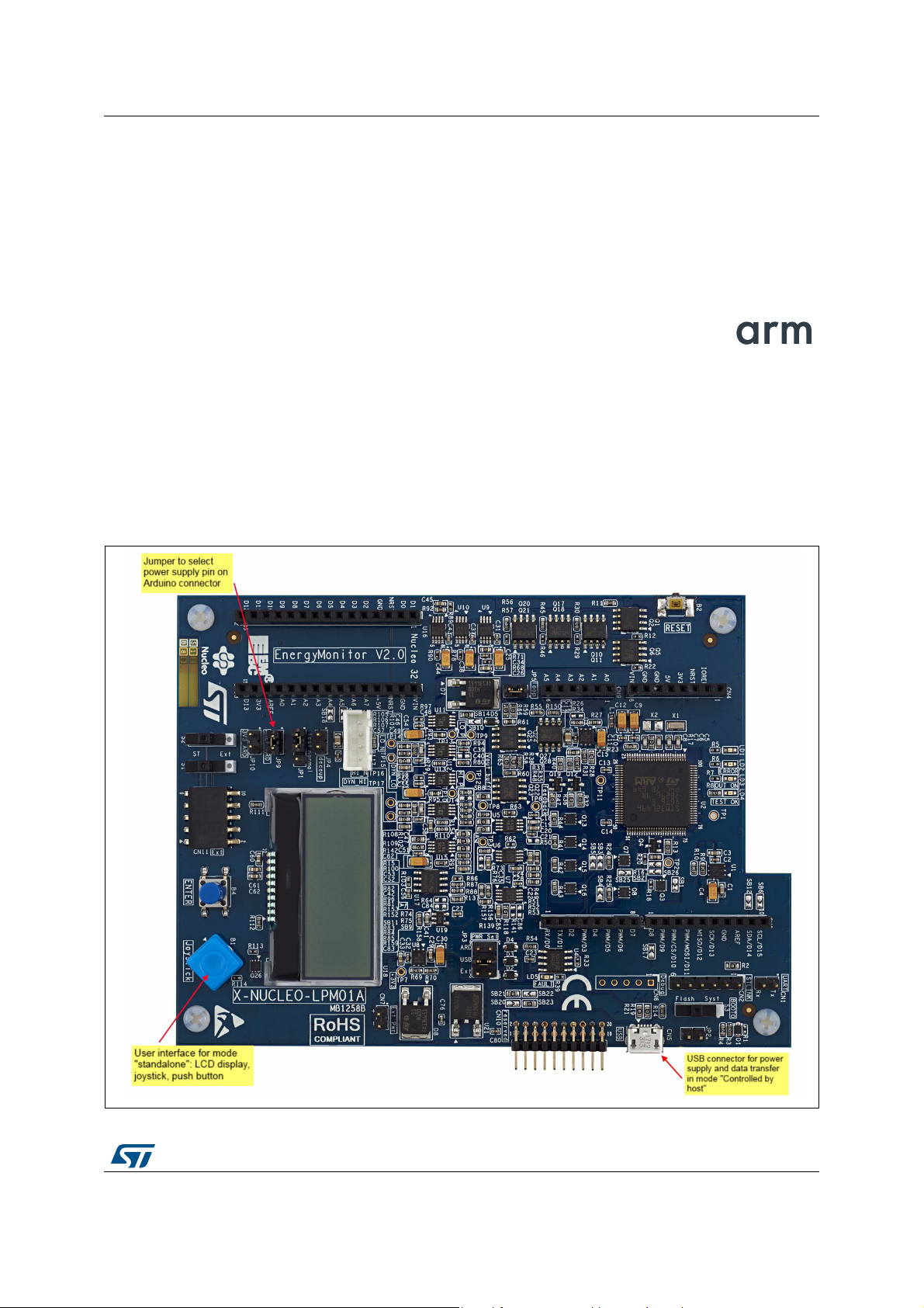
1.1 PowerShield standalone board X-NUCLEO-LPM01A
PowerShield board is designed in a user-friendly mode. All features can be controlled by
few buttons on board or USB interface.
Figure 1. PowerShield board main interface items
UM2269 Rev 6 7/59
58
Page 8
Boards overview UM2269
MS46931V1
UART
connector
USB
connector
AVDD
GND
D7
D3
D2
+3V3
+5V
GND
GND
Nucleo144
Nucleo64
Connectors
(Arduino
Uno)
Generic
connector
for any
target
+3V3
or AVDD
GNDGND
GND
+5V
D2
D3
D7
AVDD
+3V3
Nucleo32
Connectors
(Arduino
Nano)
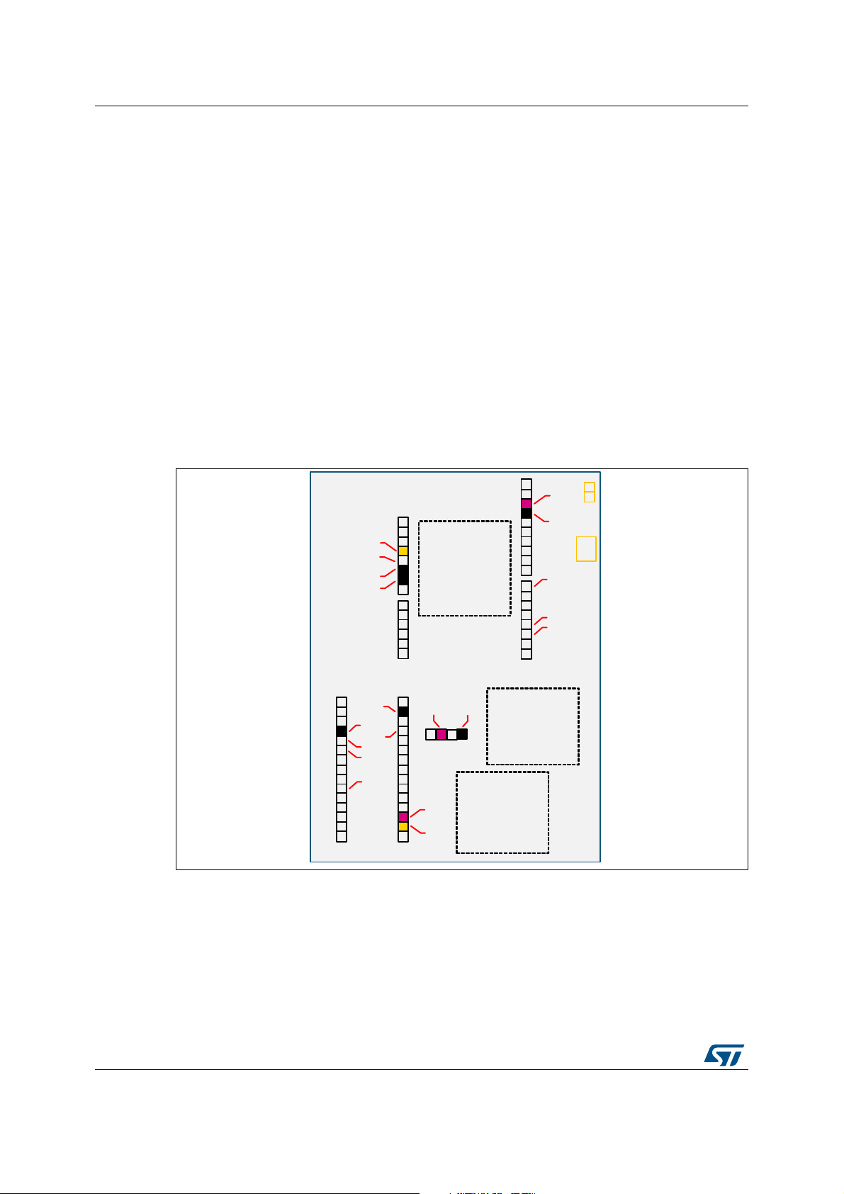
PowerShield board offers three connectors to supply target board: Nucleo64 connector,
Nucleo32 connector, basic connector for any target.
Power supply interface
Nucleo connectors have two different pins for power supply:
• +3V3: Power supply for the whole board
• AVDD (AREF): Power supply for the MCU only
PowerShield supply to one of these two pins can be selected by jumpers JP9 and JP10.
• JP10 closed: Power supply on connector +3V3
• JP9 closed: Power supply on connector AVDD
Note: Power can be supplied to one or to both pins (+3V3 and AVDD), depending on target board
configuration to be monitored.
Communication interface
Two physical interfaces are available: USB and UART (reserved for future use).
Figure 2. PowerShield connectors
8/59 UM2269 Rev 6
Page 9

UM2269 Boards overview
LED information
The board embeds four LED to inform user on PowerShield state, in standalone mode and
controlled by host mode:
• LED green (LD4): Acquisition ongoing
• LED orange (LD3): Power supply to target board (in controlled by host mode, the board
can remain supplied when the acquisition is completed)
• LED blue (LD1): Current measured above defined threshold
• LED red (LD2): Error
1.2 Quick setup to measure current on board Nucleo64 with standalone board X-NUCLEO-LPM01A
Refer to user manual STM32 Nucleo-64 boards (MB1136) (UM1724) for a complete
description of Nucleo64 board.
Setup to measure current consumption of MCU only:
• On PowerShield:
– Jumpers of power supply pin: Close jumper AREF_ARD, open jumper 3V3_ARD
• On board Nucleo64:
– Load the desired code to be executed on target board.
– Remove solder bridge SB12 to disconnect reset signal from ST-Link part (ST-Link
can still be used with this configuration to load and debug a program, software tool
option “Connect during reset” may be needed).
– Open jumper IDD
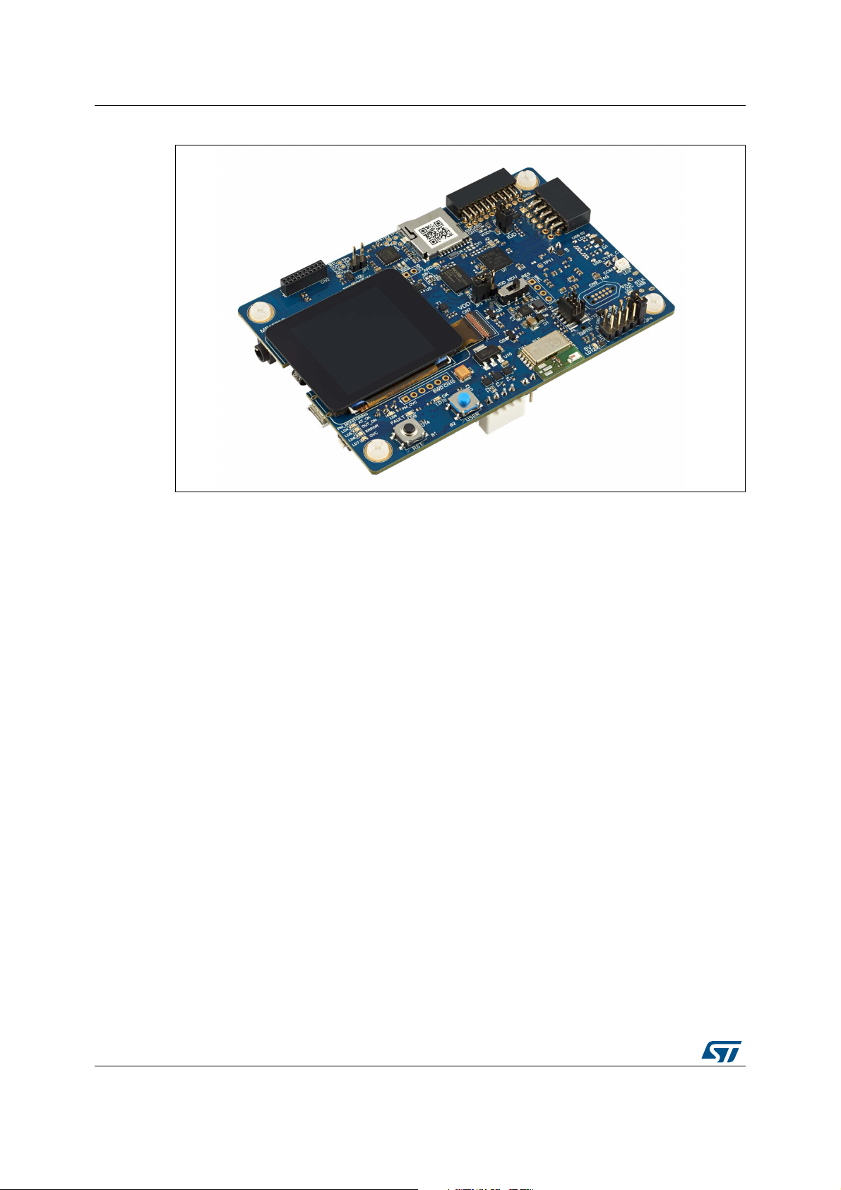
1.3 STM32L5 discovery board STM32L562E-DK
STM32L5 discovery board embeds a PowerShield circuitry to measure the STM32L5 MCU
power consumption.
It has the same features as PowerShield standalone board except that the STM32L5
discovery board must be used in host mode with computer through USB interface, moreover
the acquisition mode static is not available (dynamic mode only). Refer to
PowerShield modes and requirements and Section 5: PowerShield acquisition mode
dynamic characteristics for more details.
Section 2:
UM2269 Rev 6 9/59
58
Page 10
Boards overview UM2269
Figure 3. STM32L5 discovery board
10/59 UM2269 Rev 6
Page 11
UM2269 PowerShield modes and requirements
MS46932V1
(no software required)
USB: power supply only
10.365 uA
PowerShield
+ target board
Host: PC, ...
2 PowerShield modes and requirements
The PowerShield features up to three modes.
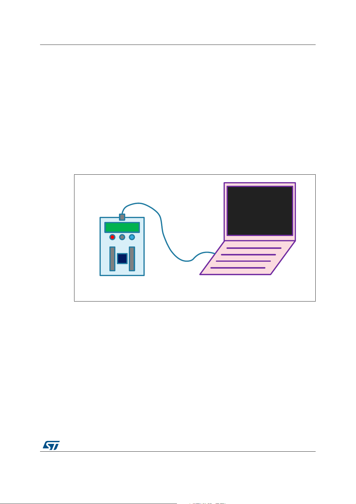
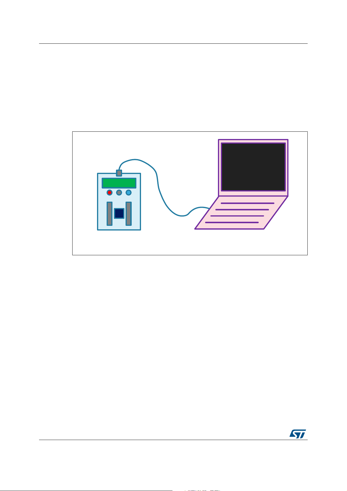
2.1 Standalone mode
This mode is available only on standalone board X-NUCLEO-LPM01A.
PowerShield is controlled with board buttons, joystick and LCD display.
It must be connected to a USB port only to get power supply from USB (does not use USB
data).
This mode can be used for quick measurements with basic settings, or for demonstrations.
Figure 4. PowerShield in standalone mode
Requirements:
• No communication interface requirement: user buttons and LCD displays are available
on board
• Power supply: 5 V must be provided either by:
– An USB connector:
a) Computer: in this case, USB enumeration is performed but USB remains
unused.
b) Charger or power bank: in this case, no USB enumeration is performed.
– A generic connector (to input 5 V):
a) External power supply
b) Battery
– Arduino connector:
a) Shield Lithium Arduino (Arduino pin +5 V)
UM2269 Rev 6 11/59
58
Page 12
PowerShield modes and requirements UM2269
MS46933V1
COM port terminal
PowerShield >
PowerShield >
USB: power supply
and data
Contr host
PowerShield
+ target board
Host: PC, ...
2.2 Controlled by host mode with commands sent by a COM port terminal
Host computer controls PowerShield through USB VCP (Virtual COM port).
The interface is a standard terminal.
This mode can be used for quick measurements with customized settings or for automation
of tests, by sending a script with PowerShield commands.
Figure 5. PowerShield in controlled by host mode with commands sent
by a COM port terminal
Requirements:
• Computer driver for USB VCP (Virtual COM port) "STM32 Virtual COM Port Driver".
Refer to driver STSW-STM32102 on STMicroelectronics web site www.st.com.
Note: On operating system Microsoft Windows 10, this driver is optional (since
PowerShield FW revision 1.0.2). By default, PowerShield can use the operating
system USB VCP driver. STMicroelectronics USB VCP driver can be installed, in
this case it takes priority over operating system driver.
• Software terminal (large variety of free terminals available on the Internet)
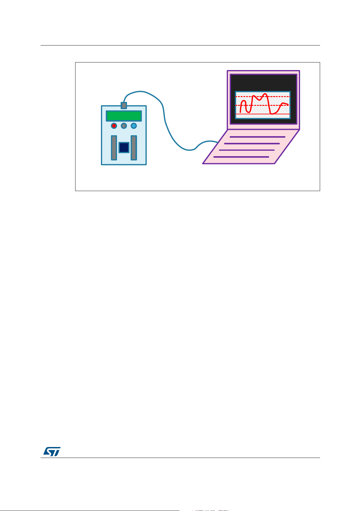
2.3 Controlled by host mode with commands sent by a GUI
PowerShield is controlled from host computer through USB VCP (Virtual COM port).
The interface is a dedicated GUI software.
This mode can be used to benefit of full capability of PowerShield measurement data:
graphical data outcomes, statistical data.
12/59 UM2269 Rev 6
Page 13
UM2269 PowerShield modes and requirements
MS46934V1
PowerMonitor software
USB: power supply
and data
Contr host
PowerShield
+ target board
Host: PC, ...
Figure 6. PowerShield in controlled by host mode with commands sent by a GUI
Requirements:
• Computer driver for USB VCP (Virtual COM port) "STM32 Virtual COM Port Driver".
Refer to driver STSW-STM32102 on STMicroelectronics web site www.st.com.
Note: On operating system Microsoft Windows 10, this driver is optional (since
PowerShield FW revision 1.0.2). By default, PowerShield can use the operating
system USB VCP driver. STMicroelectronics USB VCP driver can be installed, in
this case it takes priority over operating system driver.
• STMicroelectronics PowerShield GUI software STM32CubeMonitor-Power. Refer to
user manual STM32CubeMonitor-Power software tool for power and ultra-low-power
measurements (UM2202).
UM2269 Rev 6 13/59
58
Page 14
PowerShield standalone mode UM2269
3 PowerShield standalone mode
The communication interface available on board features:
• Two buttons:
– Reset
– Enter / Start
• One joystick.
The joystick embeds five push buttons: four directions and one in the center of joystick.
The button in the center of joystick has the same function as button “ENTER” of
keyboard.
• One LCD display: Monochrome, two lines of 16 characters
Note: A third button “reset” is available on board. It is not used as communication interface, but to
perform a reset of PowerShield FW (similar to unplug and plug the board power supply).
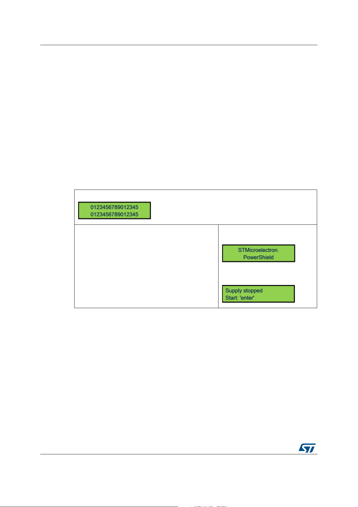
The following scheme describes standalone mode interface navigation.
1) PowerShield power-up
Welcome message for approximately two seconds.
PowerShield waits for user action.
Wait two seconds
14/59 UM2269 Rev 6
Page 15
UM2269 PowerShield standalone mode
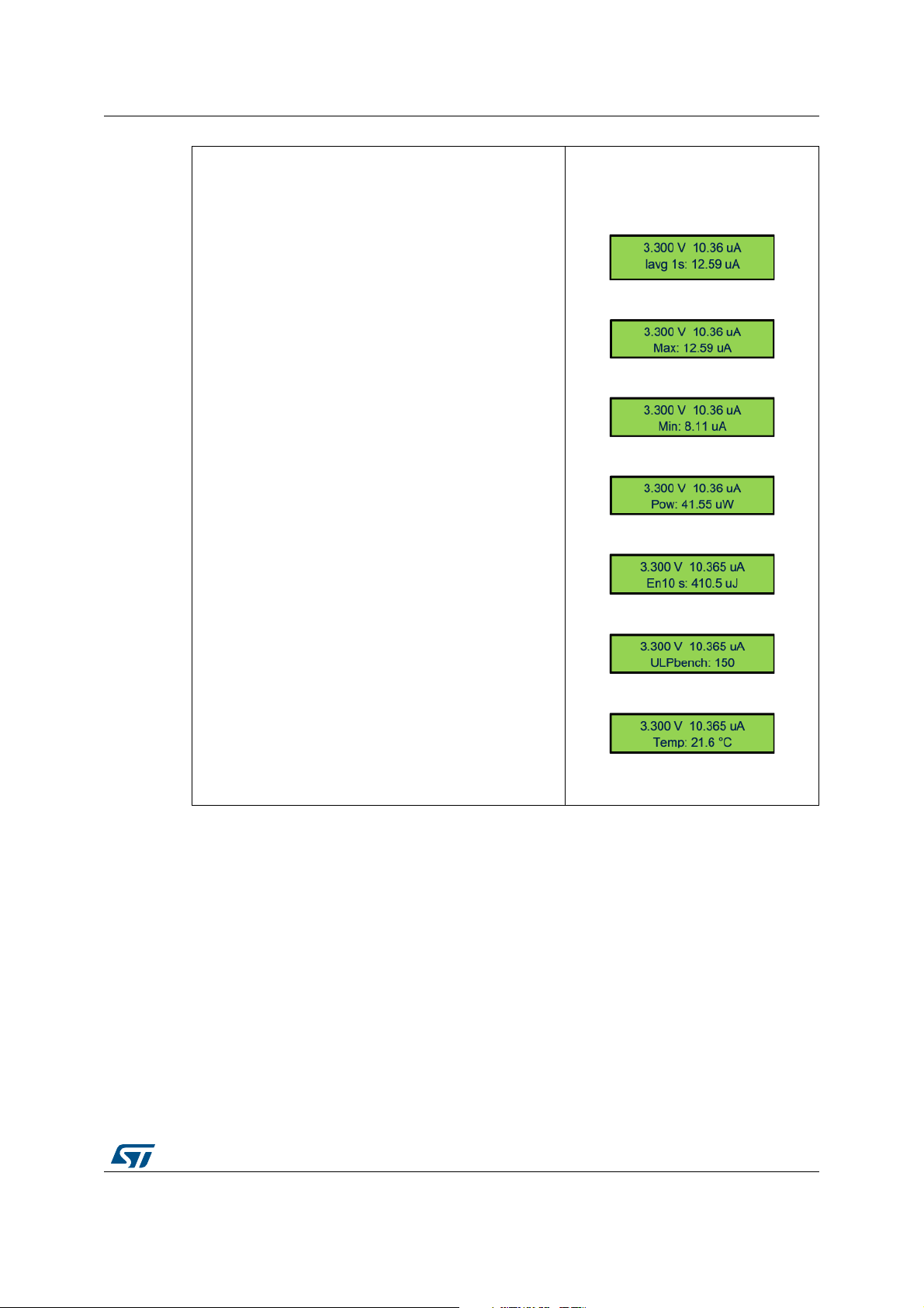
2) Acquisition mode dynamic: starts measurement and
views different data (average, power, energy, …)
From measurement stopped:
Button “enter”:
When user presses on button “enter”, PowerShield
powers-up supply of target board and starts measurement.
Default parameters:
– Power-up board, voltage: 3.0 V
– Integration time: 1 s
First line {voltage, current} is always displayed.
Voltage and current are instantaneous values (0.1 s
averages).
Second line displays different data, circularly:
– Current average with integration time
– Current max
– Current min
– Power (Watt)
– Energy (Joule) with integration time
– ULP bench score: calculation of score depending on
energy.
Prerequisite: board target must run an ULP bench
compliant program
– Temperature
Joystick down
Joystick down
Joystick down
Joystick down
Joystick down
Joystick down
(Joystick up doing the same in reverse
order)
UM2269 Rev 6 15/59
58
Page 16
PowerShield standalone mode UM2269
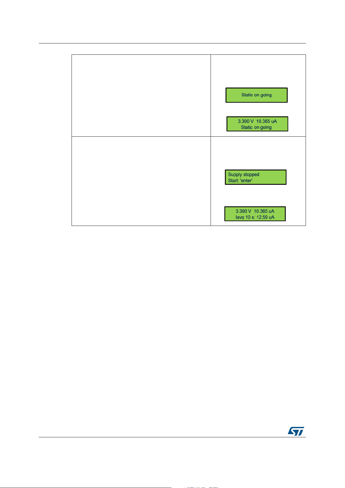
3) Acquisition mode static: starts measurement and views
data
From measurement stopped:
Button “enter”:
To start a new acquisition without switching-off the power
supply of target: press joystick up or down
4) Acquisition mode dynamic and static: stops and starts
new measurement
Button “enter” toggles stop and start measurement.
Wait few tens of ms
From measurement ongoing:
Button “enter”:
When measurement is stopped, power supply of target is
switched-off.
From measurement stopped:
Button “enter”:
16/59 UM2269 Rev 6
Page 17
UM2269 PowerShield standalone mode
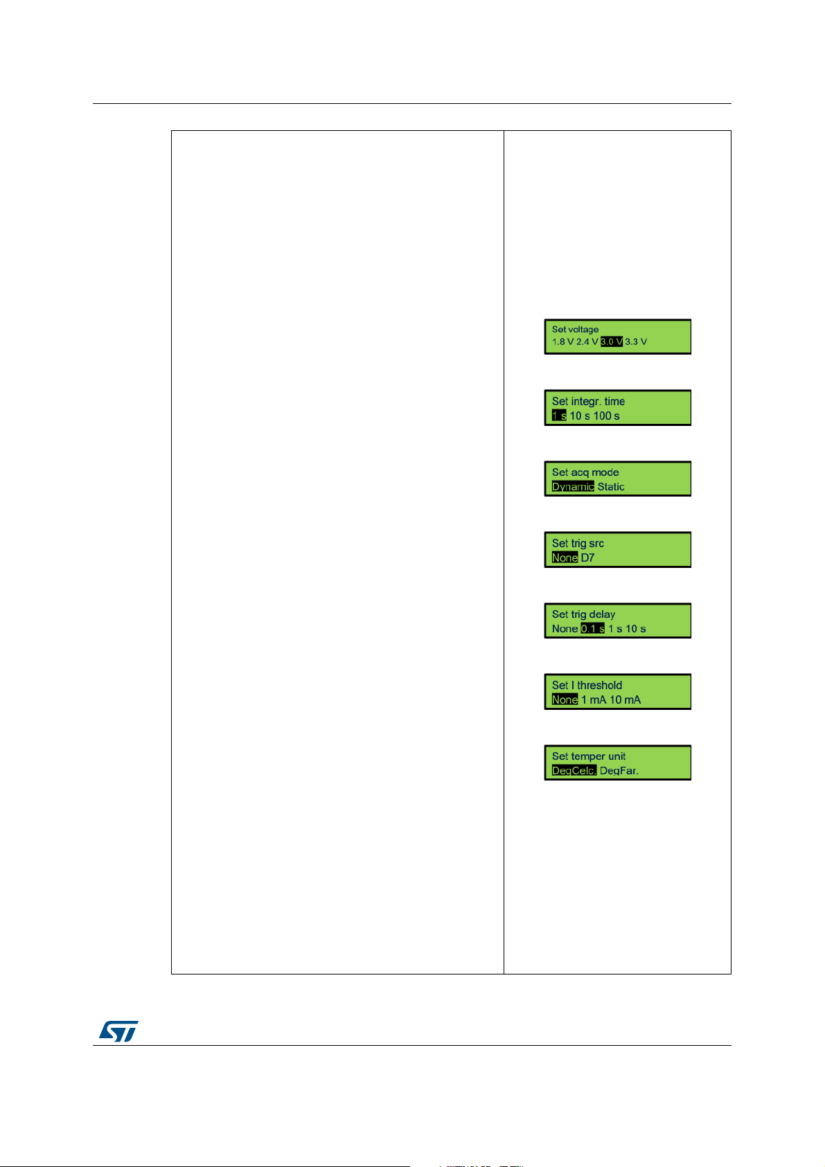
5) Changes measurement settings: configuration menu.
Rolling menu with configuration items one by one.
Each item has few parameters selectable.
Cursor moving: joystick to the right (after last parameter,
roll back to first parameter).
Back (Exit from configuration menu): joystick to the left.
6) Changes configuration: voltage
Applies for acquisition mode: dynamic and static.
Parameters:
– 1.8 V
– 2.4 V
– 3.0 V
– 3.3 V
5) Integration time.
Applies for acquisition mode: dynamic.
Parameters:
–1 s
– 10 s
– 100 s
In data display, “Iavg xxx” and “Energ xxx” show the
selected value.
8) Change configuration: acquisition mode.
Parameters:
– Dynamic (default)
– Static
9) Changes configuration: trigger source.
Applies for acquisition mode: dynamic and static.
Parameters:
– None
– Board Arduino connector D7 (other name: EXT_A)
10) Changes configuration: trigger delay.
Applies for acquisition mode: dynamic and static.
Parameters:
– None
– 0.1 s
–1 s
– 10 s
11) Changes configuration: current threshold.
Applies for acquisition mode: dynamic.
Parameters:
– None
–1 mA
– 10 mA
12) Changes configuration: temperature unit.
Parameters:
– Deg Celsius
– Deg Fahrenheit
Joystick to the right
Joystick down
Joystick down
Joystick down
Joystick down
Joystick down
Joystick down
UM2269 Rev 6 17/59
58
Page 18
PowerShield standalone mode UM2269
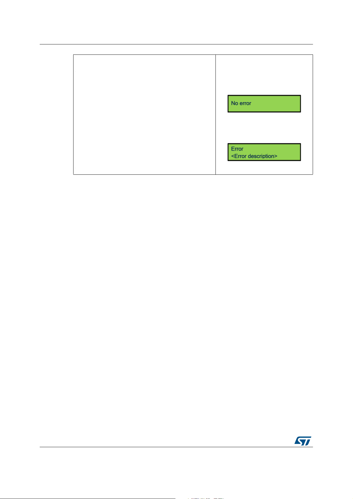
13) Error message check and release.
When LED red is turned-on, it indicates that an error is
present.
From main screen, moves joystick to the left allows the
user to check error message.
The message remains displayed for 4 s, then error status is
released: message cleared, LED red turned-off.
From main screen (all except
configuration menu):
Joystick to the left:
Case of no error:
Message displayed 1s
Case of error present:
Message displayed 4s
18/59 UM2269 Rev 6
Page 19

UM2269 PowerShield controlled by host mode
4 PowerShield controlled by host mode
To enter in controlled by host mode, user must configure the host with the serial port
described settings and sends a command to take control of PowerShield (commands
description below).
PowerShield controlled by host mode functionality:
• Power Shield enters in slave mode, master is the host.
• Role of PowerShield is to send data of measurements to host. All calculations are done
on host side.
• Message “Host control” is displayed on LCD.
• All buttons are disabled.
4.1 Serial COM port configuration
PowerShield uses the communication interface of serial COM port, USB-VCP (Virtual COM
port):
• Serial COM port configuration of USB-VCP (main interface):
– Baud rate: 3.6 Mbit/sec (3686400 bauds)
– Data: 8 bit
– Stop: 1 bit
– Parity: none
– Flow control: none
(a)
Note: The other communication interface UART is reserved for future use.
Host must use the same serial port configuration for software part (terminal, …).
Once PowerShield is plugged to host through USB, enumeration process is performed.
Enumeration process requests to host a current capability of 500
PowerShield as peripheral “STMicroelectronics Virtual COM port”.
a. On host USB virtual COM port, configuration of baud rate may be not needed since replaced by USB
maximum baudrate
mA. Host detects the
UM2269 Rev 6 19/59
58
Page 20

PowerShield controlled by host mode UM2269
Figure 7. Host detection of PowerShield
4.2 PowerShield shell
4.2.1 Transfer protocol of commands
Commands are formatted in ASCII format.
Each command sent to PowerShield must end by ASCII characters “\r\n” (carriage return,
line feed).
In case of usage of a serial COM port terminal, it must be configured accordingly.
Figure 8. Example of serial COM port terminal configuration
Each command received from PowerShield also ends by ASCII characters “\r\n”.
20/59 UM2269 Rev 6
Page 21

UM2269 PowerShield controlled by host mode
4.2.2 Transfer protocol of measurement data stream
Refer to Section 4.3.2: Command description. Several data format are available, among
them ASCII and binary.
4.2.3 Command management
The shell always replies to a command sent.
Feedback can be either:
• Acknowledge: string “ack” is sent back with the command string.
The acknowledge is followed by the command effectively applied or command returned
data.
• Error: string “err” is sent back with the command string.
On following lines, a description of the error can be sent.
The commands can take some arguments, either string or numerical values.
Numerical values of arguments can be formatted with:
• Numerical characters only (possible when numbers are ≥ 1)
• Numerical characters with unit characters 'u', 'm', 'k', 'm'
• Numerical characters with powers of ten '-xx' or '+xx' (xx: number on two digits
maximum)
Example: Value '2 milliseconds' can be entered with: '2 m' or '2-3'
4.3 Interface commands
Interface commands are available when PowerShield is in controlled by host mode.
4.3.1 Command list summary
When sending command “help” to PowerShield firmware, it returns back the list of available
commands and a short description for each command.
Common operation
help Displays list of commands
echo <arg1>
powershield
version
Table 1. List summary as displayed by firmware when entering
Command Description
Loopback to check functionality of communication Rx and Tx.
<arg1>: string of characters
Check PowerShield device availability, can be used to scan on which
serial port is connected the PowerShield.
Response: “PowerShield present” with board unique ID
Get PowerShield FW revision.
Response: “<main>.<sub1>.<sub2>”
command “help”
PowerShield commands
UM2269 Rev 6 21/59
58
Page 22

PowerShield controlled by host mode UM2269
Table 1. List summary as displayed by firmware when entering
command “help” (continued)
PowerShield commands
Command Description
htc
htc
lcd
psrst
Measurement acquisition configuration
volt <arg1>
freq <arg1>
acqtime
<arg1>
Host take control (goes from standalone mode to controlled by host
mode)
Host release control (goes from controlled by host mode to standalone
mode)
Displays a custom string on LCD display when PowerShield is controlled
by host.
<arg1>: LCD line. Numerical value among list: {1, 2}
<arg2>: string to be displayed, surrounded by double quotes and with 16
characters maximum.
Example: lcd 1 “custom display”
Note: Available only on standalone board X-NUCLEO-LPM01A.
Reset PowerShield (hardware reset, host communication have to be
restored)
Set or gets power supply voltage level, unit: V.
<arg1>: set voltage: numerical value in range [1800 m; 3300 m]
Default value: 3300 m
Get voltage: string “get” (Section 4.2.3: Command management)
Set sampling frequency, unit: Hz.
<arg1>: Numerical value among list:
{100 k, 50 k, 20 k, 10 k, 5 k, 2 k, 1 k, 500, 200 100, 50, 20, 10, 5, 2, 1}
Default value: 100 Hz (Section 4.2.3: Command management)
Set acquisition time, unit: s.
<arg1>: For limited acquisition duration:
numerical value in range: [100 µs; 10]
For infinite acquisition duration:
numerical value “0” or string “inf”
Caution: maximum acquisition time depends on other parameters. Refer
to Table 2 . Default value: 10 s (Section 4.2.3: Command management)
Set acquisition mode: dynamic or static.
Dynamic: current can vary, range [100 nA; 10 mA]
acqmode
<arg1>
22/59 UM2269 Rev 6
Static: current must be constant, range [2 nA; 200 mA] <arg1>:
string among list: {dyn, stat} available only on standalone board X-
NUCLEO-LPM01A.
Default value: “dyn”
Page 23

UM2269 PowerShield controlled by host mode
Table 1. List summary as displayed by firmware when entering
command “help” (continued)
PowerShield commands
Command Description
Set optimization of acquisition mode dynamic (applicable
only with command “output” set to parameter “current”):
optim: priority on current resolution (100 nA-10 mA), max sampling
funcmode
<arg1>
output
<arg1>
frequency at 100 kHz.
high: high current (30 µA–10 mA), high sampling frequency
(50-100 kHz), high resolution.
<arg1>: String among list: {optim, high}
Default value: “optim”
Set output type.
Current: instantaneous current.
Energy: integrated energy, reset after each sample sent
(integration time set by parameter “freq”,
limited at 100 Hz max (
<arg1>: string among list: {current, energy}
Default value: “current'”
⇔ 10 ms min)).
format <arg1>
trigsrc
<arg1>
trigdelay
<arg1>
currthre
<arg1>
Set measurement data format.
Data format 1: ASCII, decimal basis.
Format readable directly, but sampling frequency limited to 10 kHz.
Decoding: 6409-07
Data format 2: Binary, hexadecimal basis.
Format optimized data stream size.
Decoding: 52A0
<arg1>: string among list: {ascii_dec, bin_hexa}
Caution: Data format depends on other parameters. Refer to Table 2.
Default value: 'ascii_dec'
Set trigger source to start measurement acquisition.
Software trigger source (immediate trig after software start), trigger from
signal rising edge on Arduino connector D7
(via solder bridge).
<arg1>: string among list: {sw, d7}
Default value: “sw”
Set trigger delay between target power-up and starts measurement
acquisition, unit: s, resolution: 1 ms.
<arg1>: numerical value in range [0; 30]
Default value: 1 m
Set current threshold to trig an event, unit: A.
Event triggered when threshold exceeded: signal generated on Arduino
connector D2 or D3 (via solder bridge) and LED4 (green) turned on.
<arg1>: Numerical value in range [0; 10 m]
Default value: 1 m
⇔ 6409 x 10^-7 = 640.9 µA
⇔ (2A0)16 x 16^-5 = 640.9 µA
UM2269 Rev 6 23/59
58
Page 24

PowerShield controlled by host mode UM2269
Table 1. List summary as displayed by firmware when entering
command “help” (continued)
PowerShield commands
Command Description
Set target power supply connection.
– Automatic: On first run, power-on when acquisition start.Then, power
state depends on command 'pwrend'.
– Manual: Force power state.
pwr
<arg1>
<arg2>
pwrend
<arg1>
Measurement acquisition operation
start Starts current measurement
Note: Can be used during acquisition. To perform successive power off
and on, it is preferable to use command 'targrst'.
Optionally, connection status can be sent at the beginning and end of
acquisition data stream.
<arg1>: Set pwr: String among list: {'auto', 'on', 'off'}
Default value: 'auto' Get pwr: String 'get' (response: state 'on' or 'off')
<arg2>: Optional, string among list: {'nostatus', 'status'}
Default value: 'nostatus'
Set target power supply to be applied after current measurement
acquisition: power-on or power-off.
<arg1>: String among list: {on, off}
Default value: “on”
stop Stops current measurement
Reset target by disconnecting power supply during a configurable
duration, unit: s.
targrst
<arg1>
temp
<arg1>
Note: Numerical values of arguments can be formatted in:
– Numerical characters only, when numbers are ≥ 1)
– Numerical characters with unit characters “u”, “m”, “k”, “m”
– Numerical characters with power of ten “-xx” or “+xx”
(xx: number on two digits maximum)
Example: Value “2 milliseconds” can be entered with: “2 m” or “2-3”
Note: can be performed during acquisition to monitor target transient
current consumption during its power-up.
<arg1>: numerical value in range [1 m; 1]
or value “0” to let target powered-down
Gets temperature from temperature sensor on PowerShield board, on
unit: Celsius or Fahrenheit degrees
<arg1>: String among list: {degc, degf}
Default value: “degc”
24/59 UM2269 Rev 6
Page 25

UM2269 PowerShield controlled by host mode
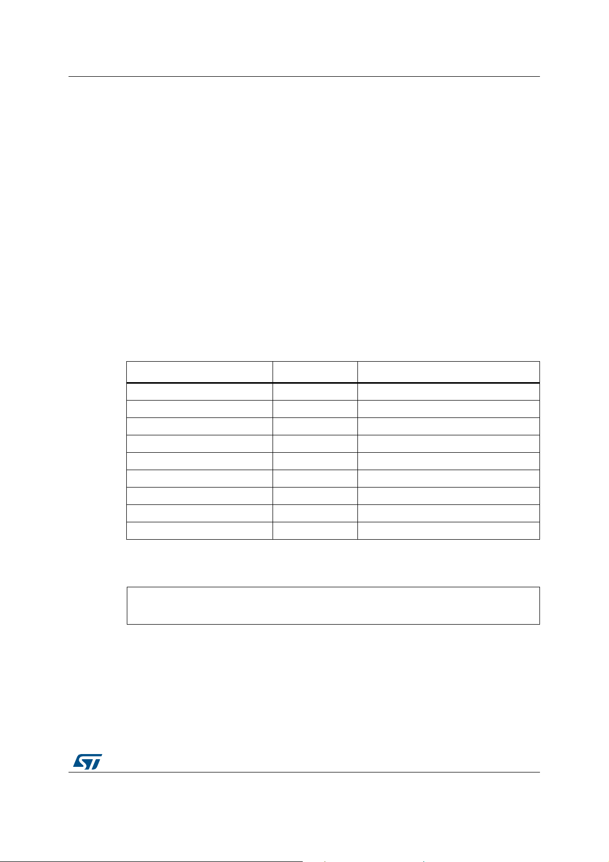
Table 2. Maximum acquisition time possible for a baudrate of 3686400 bauds
Format Frequency Acqtime max
ascii_dec ≤ 5 kHz unlimited (unlimited)
ascii_dec 10 kHz 1 s (10000)
ascii_dec 20 kHz 500 ms (5000)
bin hexa ≤ 100 kHz unlimited (unlimited)
4.3.2 Command description
1. Commands: common operation
These commands can be sent to PowerShield in both the functional standalone mode
or controlled by host mode.
Argument (none)
Description Displays list of commands
1. This command can be used when PowerShield is controlled in standalone mode.
Argument 1. String of characters
Table 3. “help” command
Table 4. “echo” command
Correspondent
number of samples
(1)
Description Loopback to check functionality of communication Rx and Tx
Table 5. “powershield” command
(1)
Argument (none)
Checks PowerShield device availability, can be used to scan on which serial port
is connected the PowerShield.
Description
Response: “PowerShield present” with board unique ID.
Example of shell feedback:
PowerShield > ack powershield 540619864-1110659081-4784204
1. This command can be used when PowerShield is controlled in standalone mode
Table 6. “version” command
(1)
Argument (none)
Gets PowerShield firmware revision.
Description
Response: “<main>.<sub1>.<sub2>”
Example of shell feedback:
PowerShield > ack version: 1.0.0
1. This command can be used when PowerShield is controlled in standalone mode.
UM2269 Rev 6 25/59
58
Page 26

PowerShield controlled by host mode UM2269
Table 7. “status” command
(1)
Argument (none)
Gets PowerShield status.
Description
Response: “ok” or “error: <error description>”
In case of error, running this command releases error status: turn-off LED red,
clear PowerShield state machine error state.
1. This command can be used when PowerShield is controlled in standalone mode.
Table 8. “htc” command
Argument (none)
Description Host takes control (goes from standalone mode to controlled by host mode)
Table 9. “hrc” command
Argument (none)
Description Host releases control (goes from controlled by host mode to standalone mode)
Argument
1. LCD line. Numerical value among list: {1, 2}
2. String to be displayed, surrounded by double quotes with 16 characters
maximum.
Example of command sent to shell:
lcd 1 " custom display"
Table 10. “lcd” command
Description
Display a custom string on LCD display when PowerShield is controlled by host.
Note: Available only on standalone board X-NUCLEO-LPM01A.
Table 11. “psrst” command
(1)
Argument (none)
Description Reset PowerShield (hardware reset, host communication have to be restored).
1. This command can be used when PowerShield is controlled in standalone mode.
26/59 UM2269 Rev 6
Page 27
UM2269 PowerShield controlled by host mode
2. Commands: measurement acquisition configuration
Table 12. “volt” command
1. Set voltage: Numerical value in range [1800 m; 3300 m]
Argument
Default value: 3000 m
Get voltage: String “get”
Description Set or gets power supply voltage level, unit: V.
Table 13. “freq” command
1. Numerical value among list:
Argument
Description Set sampling frequency, unit: Hz
{100 k, 50 k, 20 k, 10 k, 5 k, 2 k, 1 k, 500, 200, 100, 50, 20, 10, 5, 2, 1}
Default value: 100 Hz
Table 14. “acqtime” command
1. For limited acquisition duration:
– Numerical value in range: [100 µ; 10]
For infinite acquisition duration:
Argument
– Numerical value “0” or string “inf”
Caution: Maximum acquisition time depends on other parameters. Refer
to Section 5.2.1: Acquisition frequency limitations.
Default value: 10 s
Description Set acquisition time, unit: s
Argument
1. String among list: {dyn, stat}
Default value: “dyn”
Table 15. “acqmode” command
Set acquisition mode: dynamic or static.
Description
dynamic: current can vary, range [100 nA; 10 mA]
static: current must be constant, range [2 nA; 200 mA], available only on
standalone board X-NUCLEO-LPM01A.
Table 16. “funcmode” command
Argument
Description
1. String among list: {optim, high}
Default value: “optim”
Set optimization of acquisition mode dynamic (applicable only with command
“output” set to parameter “current”):
optim: priority on current resolution (100 nA-10 mA), max sampling frequency at
100 kHz.
high: high current (30 µA–10 mA), high sampling frequency (50-100 kHz), high
resolution.
Note: In mode optimized for amplitude, the benefit is to have complete dynamic
of signal [100 nA; 10 mA] but with drawback of timing artifacts (few ms
max)
UM2269 Rev 6 27/59
58
Page 28

PowerShield controlled by host mode UM2269
Argument
Description
Argument
Description
Table 17. “output” command
1. String among list: {current, energy}
Default value: “current”
Set output type.
current: instantaneous current
energy: integrated energy, reset after each sample sent (integration time set by
parameter “freq”, limited at 100 Hz max (
⇔ 10 ms min)).
Table 18. “format” command
1. String among list: {ascii_dec, bin_hexa}
Caution: Data format depends on other parameters. Refer
to Section 5.2.1: Acquisition frequency limitations.
Default value: “ascii_dec”
Set measurement data format.
Data format 1: ASCII, decimal basis.
– Format readable directly, but sampling frequency limited to 10 kHz.
Decoding: 6409-07
Data format 2: Binary, hexadecimal basis.
– Format optimized data stream size.
Decoding: 52A0
⇔ 6409 x 10^-7 = 640.9 µA
⇔ (2A0)16 x 16^-5 = 640.9 µA
Argument
Description
Table 19. “trigsrc” command
1. String among list: {sw, d7}
Default value: “sw”
Set trigger source to start measurement acquisition: trigger source software
(immediate trig after software start), trigger from external signal rising or falling
edge on Arduino connector D7 (via solder bridge).
Note: Trigger from external signal also requires command “start” (similar
software start) to arm the trigger, then following triggers are effective
without any command.
Command “stop” disarms the trigger (acquisition stop after acquisition time
elapsed does not disarm the trigger).
Note: When trigger source from Arduino connector D7 is used, the alternate
communication interface with UART connector cannot be used after
trigger is armed (due to Arduino connector D7 and UART Rx sharing the
same input).
28/59 UM2269 Rev 6
Page 29
UM2269 PowerShield controlled by host mode
Argument
Description
Argument
Description
Argument
Description
Table 20. “trigdelay” command
1. Numerical value in range [0; 600]
Default value: 1 m
Set trigger delay between target power-up and starts measurement acquisition,
unit: s, resolution: 1 ms.
This command allows the voltage and current to stabilize before start of current
acquisition.
Table 21. “currthre” command
1. Numerical value in range [0; 10 m]
Default value: 1 m
Set current threshold to trig an event, unit: A.
Event triggered when threshold exceeded: signal generated on Arduino
connector D2 or D3 (via solder bridge) and LED4 (green) turned on.
Table 22. “pwr” command
1. Set pwr: String among list: {'auto', 'on', 'off'}
Default value: 'auto'
Get pwr: String 'get' (response: state 'on' or 'off')
2. Optional, string among list: {'nostatus', 'status'}
Default value: 'nostatus'
Set target power supply connection.
– Automatic:
• On first run, power-on when acquisition start.
• Then, power state depends on command 'pwrend'.
– Manual:
• Force power state.
Note: Can be used during acquisition. To perform successive power off and on,
it is preferable to use command 'targrst'.
Optionally, connection status can be sent at the beginning and end of acquisition
data stream.
Note: This command is available since PowerShield FW revision 1.0.2.
Argument
Description
1. String among list: {on, off}
Default value: “on”
Set target power supply to be applied after current measurement acquisition:
power-on or power-off.
Table 23. “pwrend” command
3. Commands: Measurement acquisition operation
Argument (none)
Description
Starts acquisition (measurement of current or energy depending on
configuration).
Table 24. “start” command
UM2269 Rev 6 29/59
58
Page 30
PowerShield controlled by host mode UM2269
Argument (none)
Description
Stops acquisition. If acquisition is set to a finite duration, it stops when reaching
the target duration.
Argument
1. Numerical value in range [1 m; 1]
or value “0” to let target power-down.
Reset target by disconnecting power supply during a configurable duration,
Description
Argument
unit: s.
Note: can be performed during acquisition to monitor target transient current
1. String among list: {degc, degf}
Default value: “degc”
Gets temperature from temperature sensor on PowerShield board, on unit:
Celsius or Fahrenheit degrees.
Note: reported temperature is an approximation of ambient temperature;
Description
Table 25. “stop” command
Table 26. “targrst” command
consumption during its power-up.
Table 27. “temp” command
measured temperature corresponds to temperature on board surface,
which is higher than ambient temperature of approximatively 3 Celsius
degrees (due to board self-heating with surrounding components),
therefore this value is subtracted to measured temperature on board
surface.
In case of specific conditions (for example, forced convection in a
laboratory oven), user must apply a temperature offset to reported
temperature.
4. Commands: Board state operation
Argument
1. Optional: string among list: {start, status}
or no argument equivalent to value: “start”
Performs board auto-test and display auto-test results.
Description
Note: auto-test is done at PowerShield power-up.
Argument (none)
Performs board self-calibration.
Description
Note: new calibration should be performed when temperature shifts of more than
30/59 UM2269 Rev 6
Table 28. “autotest” command
Argument “status” can be used to check results of auto-test done at
PowerShield power-up.
Table 29. “calib” command
5 °C since the previous calibration.
Page 31
UM2269 PowerShield controlled by host mode
6409()1010
7–
× 640.9 106–⋅ 640.9==μA
4.4 Data stream format
Measurement data contain the main information: current or energy (depending on
configuration sent to PowerShield shell).
Note: Information of voltage is not sent. Effective voltage is assumed to be close to targeted
voltage (tolerance approximatively ±1%).
Note: Information of timing is not sent and must be deduced from data count. For example, if the
acquisition frequency is set at 10
to 20
µs, the third data to 30 µs, and so on.
4.4.1 Data format 1: ASCII, decimal basis
1. Measurement data of current or energy
Format intended when PowerShield is used with a COM port terminal: data are
formatted in ASCII characters, values are in decimal basis.
Note: Due to higher data size in ASCII format and to data bandwidth constraints, this data format
can be used with a sampling up to 10
Each measurement data is formatted on eight ASCII characters:
Table 30. ASCII characters description
kHz, the first data corresponds to 10 µs, the second data
ksamples/sec.
Byte on serial port Byte number Description
ASCII [0; 9] 1 Current measurement digit 4
ASCII [0; 9] 2 Current measurement digit 3
ASCII [0; 9] 3 Current measurement digit 2
ASCII [0; 9] 4 Current measurement digit 1
ASCII {‘-’;’+’} 5 Current measurement power of 10 sign
ASCII [0; 9] 6 Current measurement power of 10 value
ASCII [0; 9] 7 Current measurement power of 10 value
ASCII ‘\r’ 8 Carriage return
ASCII ‘\n’ 9 Line feedback
Example of data stream and corresponding conversion to decimal values:
6409*10
-7
2. Metadata inserted into data stream
Metadata are inserted into data stream to provide other information.
Data must be filtered in data stream to isolate measurement data (current or energy
values) versus metadata.
UM2269 Rev 6 31/59
58
Page 32

PowerShield controlled by host mode UM2269
Differentiator of measurement data versus metadata:
– Measurement data are beginning by a number in ASCII format (first byte
corresponding to decimal values from 48 to 57).
– Metadata are beginning with a letter in ASCII format (first byte corresponding to
decimal value other than a number, described above).
Metadata: Timestamp and buffer Tx load
Each 1000 samples, a timestamp is sent.
It can be used to check data count matches with each timestamp occurrence, and to
resynchronize timing if some data have been lost.
Timestamp also includes information of time elapsed in milliseconds.
Additionally, the information of PowerShield buffer Tx load is added after time elapsed.
It is useful in case host encounters a delay on USB bus (can occur when host is busy by
CPU load or file access delay), to take appropriate action before buffer overload and
acquisition stop.
Timestamp format: ASCII, decimal format
Table 31. Timestamp, format 1: ASCII characters description
Byte on serial port Byte number Description
ASCII ‘\r’ 1 Carriage return
ASCII ‘\n’ 2 Line feedback
ASCII ‘T’ 3 Timestamp tag characters
ASCII ‘i’ 4 Timestamp tag characters
ASCII ‘m’ 5 Timestamp tag characters
ASCII ‘e’ 6 Timestamp tag characters
ASCII ‘s’ 7 Timestamp tag characters
ASCII ‘t’ 8 Timestamp tag characters
ASCII ‘a’ 9 Timestamp tag characters
ASCII ‘m’ 10 Timestamp tag characters
ASCII ‘p’ 11 Timestamp tag characters
ASCII ‘:’ 12 Timestamp tag characters
ASCII ‘ ’ 13 Timestamp tag characters
ASCII [0; 9] 14 Timestamp value in s, digit 2
ASCII [0; 9] 15 Timestamp value in s, digit 1
ASCII [0; 9] 16 Timestamp value in s, digit 0
ASCII ‘s’ 17 Timestamp value character
ASCII ‘ ‘ 18 Timestamp value character
ASCII [0; 9] 19 Timestamp value in ms, digit 2
ASCII [0; 9] 20 Timestamp value in ms, digit 1
ASCII [0; 9] 21 Timestamp value in ms, digit 0
32/59 UM2269 Rev 6
Page 33

UM2269 PowerShield controlled by host mode
Table 31. Timestamp, format 1: ASCII characters description (continued)
Byte on serial port Byte number Description
ASCII ‘m’ 22 Timestamp value character
ASCII ‘s’ 23 Timestamp value character
ASCII ‘,‘ 24 Timestamp tag characters
ASCII ‘ ‘ 25 Timestamp tag characters
ASCII ‘b‘ 26 Timestamp tag characters
ASCII ‘u‘ 27 Timestamp tag characters
ASCII ‘f‘ 28 Timestamp tag characters
ASCII ‘f‘ 29 Timestamp tag characters
ASCII ‘ ‘ 30 Timestamp tag characters
ASCII [0; 9] 31 Buffer Tx load value in percent, digit 1
ASCII [0; 9] 32 Buffer Tx load value in percent, digit 0
ASCII ‘%‘ 33 Timestamp tag characters
ASCII ‘\r‘ 34 Carriage return
ASCII ‘\n ‘ 35 Line feedback
Metadata: Error
An error message (voltage drop) can be sent as a stream of ASCII characters.
Byte on serial port Byte number Description
Table 32. Error, format 1: ASCII characters description
ASCII ‘\r‘ 1 Carriage return
ASCII ‘\n ‘ 2 Line feedback
ASCII ‘e‘ 3 Error tag characters
ASCII ‘r‘ 4 Error tag characters
ASCII ‘r‘ 5 Error tag characters
ASCII ‘o‘ 6 Error tag characters
ASCII ‘r‘ 7 Error tag characters
ASCII char 8 Message content: ASCII character
ASCII char ... Message content: ASCII character
ASCII char x Message content: ASCII character
ASCII char x + 1 Message content: ASCII character
ASCII ‘\r’ x + 2 Carriage return
ASCII ‘\n’ x + 3 Line feedback
UM2269 Rev 6 33/59
58
Page 34

PowerShield controlled by host mode UM2269
Metadata: End of acquisition
Metadata send when acquisition is completed: integration time reached or command
“stop” sent by user, and all data in Tx buffer sent to host.
Table 33. End of acquisition, format 1: ASCII characters description
Byte on serial port Byte number Description
ASCII ‘\r‘ 1 Carriage return
ASCII ‘\n ‘ 2 Line feedback
ASCII ‘e‘ 3 End of acquisition tag characters
ASCII ‘n‘ 4 End of acquisition tag characters
ASCII ‘d‘ 5 End of acquisition tag characters
ASCII ‘\r‘ 6 Carriage return
ASCII ‘\n ‘ 7 Line feedback
Metadata: Power to target connection
Metadata sent as acknowledge and data of command “pwr get”.
Metadata also sent at the beginning (after metadata of acquisition start) and end (before
metadata of acquisition end) of each acquisition if second parameter of command “pwr” is
set to argument “status” (optional).
Power to target connection status is coded on two or three characters:
“off” <=> power off (power supply disconnected from target)
“on” <=> power on (power supply connected to target)
Table 34. Power to target, format 1: ASCII characters description
Byte on serial port Byte number Description
ASCII ‘\r‘ 1 Carriage return
ASCII ‘\n ‘ 2 Line feedback
ASCII ‘p‘ 3 Power to target tag characters
ASCII ‘w‘ 4 Power to target tag characters
ASCII ‘r‘ 5 Power to target tag characters
ASCII ‘ ‘ 6 Power to target tag characters
ASCII char 7 Power to target connection status characters
ASCII char 8 Power to target connection status characters
ASCII char ... Power to target connection status characters
ASCII ‘\r‘ x Carriage return
ASCII ‘\n ‘ x Line feedback
34/59 UM2269 Rev 6
Page 35

UM2269 PowerShield controlled by host mode
Metadata: Summary
After end of acquisition, a summary is displayed between tags “summary begin” and
“summary end”.
Description and data sent in ASCII: acquisition mode, sampling frequency
Table 35. Summary, format 1: ASCII characters description
Byte on serial port Byte number Description
ASCII ‘\r‘ 1 Carriage return
ASCII ‘\n ‘ 2 Line feedback
ASCII ‘s‘ 3 Summary tag characters
ASCII ‘u‘ 4 Summary tag characters
ASCII ‘m‘ 5 Summary tag characters
ASCII ‘m‘ 6 Summary tag characters
ASCII ‘a‘ 7 Summary tag characters
ASCII ‘r‘ 8 Summary tag characters
ASCII ‘y‘ 9 Summary tag characters
ASCII ‘ ‘ 10 Summary tag characters
ASCII ‘b‘ 11 Summary tag characters
ASCII ‘e‘ 12 Summary tag characters
ASCII ‘g‘ 13 Summary tag characters
ASCII ‘\r‘ 14 Carriage return
ASCII ‘\n ‘ 15 Line feedback
ASCII [0; 9] 16 current measurement min digit 4
ASCII [0; 9] 17 current measurement min digit 3
ASCII [0; 9] 18 current measurement min digit 2
ASCII [0; 9] 19 current measurement min digit 1
ASCII {‘-’; ‘+’} 20 current measurement min power of 10 sign
ASCII [0; 9] 21 current measurement min power of 10 value
ASCII [0; 9] 22 current measurement min power of 10 value
ASCII ‘\r‘ 23 Carriage return
ASCII ‘\n ‘ 24 Line feedback
ASCII [0; 9] 25 current measurement max digit 4
ASCII [0; 9] 26 current measurement max digit 3
ASCII [0; 9] 27 current measurement max digit 2
ASCII [0; 9] 28 current measurement max digit 1
ASCII {‘-’; ‘+’} 29 current measurement max power of 10 sign
ASCII [0; 9] 30 current measurement max power of 10 value
ASCII [0; 9] 31 current measurement max power of 10 value
UM2269 Rev 6 35/59
58
Page 36

PowerShield controlled by host mode UM2269
Table 35. Summary, format 1: ASCII characters description (continued)
Byte on serial port Byte number Description
ASCII ‘\r‘ 32 Carriage return
ASCII ‘\n ‘ 33 Line feedback
ASCII ‘s‘ 34 Summary tag characters
ASCII ‘u‘ 35 Summary tag characters
ASCII ‘m‘ 36 Summary tag characters
ASCII ‘m‘ 37 Summary tag characters
ASCII ‘a‘ 38 Summary tag characters
ASCII ‘r‘ 39 Summary tag characters
ASCII ‘y‘ 40 Summary tag characters
ASCII ‘ ‘ 41 Summary tag characters
ASCII ‘e‘ 42 Summary tag characters
ASCII ‘n‘ 43 Summary tag characters
ASCII ‘d‘ 44 Summary tag characters
ASCII ‘\r‘ 45 Carriage return
ASCII ‘\n ‘ 46 Line feedback
4.4.2 Data format 2: Binary, hexadecimal basis
1. Measurement data of current or energy
Format intended when PowerShield is used with host software “Power Monitor”:
software must decode data from hexadecimal to decimal.
This data format is optimized to have to lowest data width per measurement data.
Each measurement data is formatted on two bytes (binary value, not ASCII):
– Data size of two bytes characters compresses data size as much as possible (it
allows the user to transmit a data stream of 50 ksamples/sec at bit rate
921.600 kbps).
– Each data is coded in hexadecimal: 12 bits of data and four bits of negative power
of 16.
Data accuracy: Decimation error of base 16 is data ±0.20% worst case.
Serial
data 1
Current
neg
pow16
bit 3
Serial
data 2
Current
neg
pow16
bit 2
Serial
data 3
Current
neg
pow16
bit 1
Table 36. Serial byte 1
Serial
data 4
Current
neg
pow16
bit 0
Serial
data 5
Current
value
bit 11
Serial
data 6
Current
value
bit 10
Serial
data 7
Current
value
bit 9
Serial
data 8
Current
value
bit 8
Serial
stop bit
36/59 UM2269 Rev 6
Page 37

UM2269 PowerShield controlled by host mode
2A0()1616
5–
× 672()10165⁄ 640.9 106–⋅ 640.9===μA
145()1616
3–
× 325()10163⁄ 793.5 104–⋅ 79.35===mA
Serial
data 1
Current
value
bit 7
Serial
data 2
Current
value
bit 6
Serial
data 3
Current
value
bit 5
Table 37. Serial byte 2
Serial
data 4
Current
value
bit 4
Serial
data 5
Current
value
bit 3
Serial
data 6
Current
value
bit 2
Serial
data 7
Current
value
bit 1
Serial
data 8
Current
value
bit 0
Serial
stop bit
Example of measurement data sent on serial port and corresponding conversion to decimal
values:
52A0:
3145:
Note: Negative power of 16 is typically in the range of [-10; -3], allowing a current range of [0.2 nA;
999
mA].
Note: Negative power of 16 is limited to range {0 (0x0; 14 (0xE)}. Value 15 (0xF) is reserved as an
information tag (refer to time stamp description).
2. Metadata inserted into data stream
Metadata is inserted into data stream to provide other information.
Data must be filtered in data stream to isolate measurement data (current or energy
values) versus metadata.
Differentiator of measurement data versus metadata:
• Metadata
– Metadata start: two consecutive bytes starting by 0xF (measurement data can
have only one of the bytes having this value): 0xF0 and 0xFx (value
depending on metadata type, see Table 38)
– Metadata stop: two consecutive bytes at value 0xFF.
• Measurement data: All other data
Metadata: Error
An error message (voltage drop) can be sent as a stream of ASCII characters.
Byte on serial port Byte number Description
0xF0 1 Metadata beginning tag
0xF1 2 Metadata ASCII error message tag
ASCII char 3 Message content: ASCII character
Table 38. Metadata error
ASCII char ... Message content: ASCII character
UM2269 Rev 6 37/59
58
Page 38

PowerShield controlled by host mode UM2269
Table 38. Metadata error (continued)
Byte on serial port Byte number Description
ASCII char x Message content: ASCII character
ASCII char x + 1 Message content: ASCII character
Message content: ASCII value of carriage
‘\r’ x + 2
‘\n’ x + 3
0xFF x + 4 Metadata end tag (1/2)
0xFF x + 5 Metadata end tag (2/2)
return, for indication in case of data stream
watched in terminal
Message content: ASCII value of line
feedback, for indication in case of data
stream watched in terminal
Metadata: Information
Similar to error message, with a different metadata tag.
Table 39. Metadata information
Byte on serial port Byte number Description
0xF0 1 Metadata beginning tag
0xF2 2 Metadata ASCII information message tag
ASCII char 3 Message content: ASCII character
ASCII char ... Message content: ASCII character
ASCII char x Message content: ASCII character
ASCII char x + 1 Message content: ASCII character
Message content: ASCII value of carriage
‘\r’ x + 2
‘\n’ x + 3
0xFF x + 4 Metadata end tag (1/2)
0xFF x + 5 Metadata end tag (2/2)
return, for indication in case of data stream
watched in terminal
Message content: ASCII value of line
feedback, for indication in case of data
stream watched in terminal
Metadata: Timestamp
Each 1000 samples, a timestamp is sent.
It can be used to check data count matches with each timestamp occurrence and
resynchronize timing in case of some data have been lost.
Timestamp also includes information of time elapsed in milliseconds.
Additionally, the information of PowerShield buffer Tx load is added after time elapsed.
38/59 UM2269 Rev 6
Page 39

UM2269 PowerShield controlled by host mode
It is useful in case of host encounters a delay on USB bus (can occur when host is busy by
CPU load or file access delay), to take appropriate action before buffer overload and
acquisition stop.
Timestamp format: Binary, nine bytes
Byte on serial port Byte number Description
0xF0 1 Metadata beginning tag
0xF3 2 Metadata timestamp message tag
x 3 Timestamp value in ms, byte 3
x 4 Timestamp value in ms, byte 2
x 5 Timestamp value in ms, byte 1
x 6 Timestamp value in ms, byte 0
x 7 Buffer Tx load value in percent, byte 0
0xFF 8 Metadata end tag (1/2)
0xFF 9 Metadata end tag (2/2)
Table 40. Metadata timestamp
Note: Timestamp value is coded on four bytes:
- Timing value is coded on 31 bits (value from 0 to 2147483647: allowing unique timestamps
up to two million of seconds, equivalent to 23 days)
- Bit 32 is used to indicate counter overflow. In case of overflow, bit 32 is set and timing
value is restarting from zero.
Metadata: End of acquisition
Metadata send when acquisition is completed: integration time reached or command “stop”
sent by user, and all data in Tx buffer sent to host.
Metadata format: Binary, four bytes
Byte on serial port Byte number Description
0xF0 1 Metadata beginning tag
0xF4 2 Metadata end of acquisition tag
0xFF 3 Metadata end tag (1/2)
0xFF 4 Metadata end tag (2/2)
Table 41. Metadata end of acquisition
Metadata: Overcurrent
Metadata send when current sinked by target device exceeds board maximum suply
capacity
Metadata format: Binary, four bytes
UM2269 Rev 6 39/59
58
Page 40

PowerShield controlled by host mode UM2269
Table 42. Metadata overcurrent
Byte on serial port Byte number Description
0xF0 1 Metadata beginning tag
0xF4 2 Metadata overcurrent tag
0xFF 3 Metadata end tag (1/2)
0xFF 4 Metadata end tag (2/2)
Metadata: Acknowledge and data of command “target reset (target power
down)”
Metadata send (in format binary) after command from host is received (in format ASCII),
only under conditions:
– Acquisition is ongoing
Metadata format: Binary, four bytes
Byte on serial port Byte number Description
0xF0 1 Metadata beginning tag
0xF6 2 Metadata target power down tag
0xFF 3 Metadata end tag (1/2)
Table 43. Metadata target power down
0xFF 4 Metadata end tag (2/2)
Metadata: Acknowledge and data of command “Voltage get”
Metadata send (in binary format) after command from host is received (in ASCII format),
only under conditions:
– Acquisition is ongoing
Metadata format: Binary, six bytes
Voltage is coded on two bytes on format unsigned:
0x0CE4 ⇔ 3300 mV
0x0708 ⇔ 1800 mV
Table 44. Metadada Acknowledge and data command “voltage get”
Byte on serial port Byte number Description
0xF0 1 Metadata beginning tag
0xF7 2 Metadata voltage tag
x 3 Voltage value in mV, byte 1
x 4 Voltage value in mV, byte 0
0xFF 5 Metadata end tag (1/2)
0xFF 6 Metadata end tag (2/2)
40/59 UM2269 Rev 6
Page 41

UM2269 PowerShield controlled by host mode
Metadata: Acknowledge and data of command “Temperature”
Metadata send (in binary format) after command from host is received (in ASCII format),
only under conditions:
– Acquisition is ongoing
Metadata format: Binary, six bytes
Temperature is coded on two bytes on format signed:
0x000A ⇔ +10 degC
0xFFFD ⇔ -3 degC
Byte on serial port Byte number Description
0xF0 1 Metadata beginning tag
0xF8 2 Metadata temperature tag
x 3 Temperature value in degC, byte 1
x 4 Temperature value in degC, byte 0
0xFF 5 Metadata end tag (1/2)
Table 45. Metadata temperature
0xFF 6 Metadata end tag (2/2)
Metadata: Acknowledge and data of command “pwr get”
Metadata send (in format binary) after command from host is received (in format ASCII),
only under conditions:
• Acquisition is on going
• Acquisition is armed and not started (case of trigger D7 selected, command “start” sent
and signal event of connector D7 not yet occurred).
Metadata also sent at the beginning (after metadata of acquisition start) and end (before
metadata of acquisition end) of each acquisition if second parameter of command “pwr” is
set to argument “status” (optional).
Metadata format: Binary, 5 bytes
Power to target connection status is coded on 1 byte:
0x0 <=> power off (power supply disconnected from target)
0x1 <=> power on (power supply connected to target)
Byte on serial port Byte number Description
0xF0 1 Metadata beginning tag
0xF9 2 Metadata power to target connection tag
Table 46. Metadata power to target connection
x 3 Power to target connection, byte 1
UM2269 Rev 6 41/59
58
Page 42

PowerShield controlled by host mode UM2269
Table 46. Metadata power to target connection (continued)
Byte on serial port Byte number Description
0xFF 4 Metadata end tag (1/2)
0xFF 5 Metadata end tag (2/2)
Metadata reserved
Metadata reserved for potential future usage:
{0xF0; 0xF5}
{0xF0; 0xFE}
Example of data stream
Measurement with 150 data.
Table 47. Example of data stream in format 2: Binary, hexadecimal basis
Byte on serial port Byte number Description
0xF0 1
0xF3 2
0x00 3
0x00 4
0x00 5
0x00 6
0x00 7
0xFF 8
0xFF 9
0x3A 10 Measurement data 1 (1/2)
0xB8 11 Measurement data 1 (2/2)
0x3C 12 Measurement data 2 (1/2)
0x86 13 Measurement data 2 (2/2)
... ... ...
... ... ...
0x47 208 Measurement data 99 (1/2)
0x16 209 Measurement data 99 (2/2)
Metadata: Timestamp 0 ms
42/59 UM2269 Rev 6
Page 43

UM2269 PowerShield controlled by host mode
Table 47. Example of data stream in format 2: Binary, hexadecimal basis (continued)
Byte on serial port Byte number Description
0xF0 210
0xF1 211
0x00 212
0x00 213
0x00 214
0x01 215
0xFF 216
0xFF 217
0x5E 218 Measurement data 100 (1/2)
0xB1 219 Measurement data 100 (2/2)
0x5C 220 Measurement data 101 (1/2)
0x27 221 Measurement data 101(2/2)
... ... ...
... ... ...
0x47 - Measurement data 150 (1/2)
Metadata: Timestamp 0 ms
0x16 - Measurement data 150 (2/2)
0xF0 -
0xF4 -
0xFF -
0xFF -
0xF0 -
... -
... -
... -
... -
... -
... -
... -
4.5 Examples of typical use cases
4.5.1 Minimal mandatory commands
Metadata: end of acquisition
Data post-acquisition: summary
The not used commands are implicitly used with default settings.
UM2269 Rev 6 43/59
58
Page 44

PowerShield controlled by host mode UM2269
Table 48. Minimal mandatory commands
Data sent by host Data sent by PowerShield
(Not displayed) COM port terminal
htc
start
PowerShield > ack htc
PowerShield > ack start
1958-09
2041-09
(delay)
...
1853-09
1742-09
end
hrc PowerShield > ack hrc
4.5.2 Continuous measurement (infinite samples) with target reset during acquisition
Data sent by host Data sent by PowerShield
Table 49. Continuous measurement
(Not displayed) COM port terminal
htc
volt 3300 m (or “volt 3300-3”)
freq 1 k (or “freq 1000", or “freq 1+3”)
acqtime inf (or “acqtime 0")
PowerShield > ack htc
PowerShield > ack volt 3300 m
PowerShield > ack freq 1 k
PowerShield > ack acqtime inf
start
PowerShield > ack start
11958-09
(delay)
2041-09
...
1853-09
targrst 100 m PowerShield > ack targrst 100 m
0023-10
0008-10
(delay)
...
1742-09
2013-09
end
hrc PowerShield > ack hrc
44/59 UM2269 Rev 6
Page 45

UM2269 PowerShield controlled by host mode
4.5.3 Two single measurements of 100 samples with power-down of board under test at the end of acquisition
Table 50. Two single measurements of 100 samples
Data sent by host Data sent by PowerShield
(Not displayed) COM port terminal
htc
volt 3300 m PowerShield > ack htc
PowerShield > ack volt 3300 m
freq 1 k PowerShield > ack freq 1 k
acqtime 100 m PowerShield > ack acqtime 100 m
pwrend off PowerShield > pwrend off
start PowerShield > ack start
1958-09
(delay)
2041-09
...
1853-09
end
start PowerShield > ack start
1958-09
(delay)
2041-09
...
1853-09
end
hrc PowerShield > ack hrc
UM2269 Rev 6 45/59
58
Page 46

PowerShield acquisition mode dynamic characteristics UM2269
5 PowerShield acquisition mode dynamic
characteristics
5.1 Acquisition range and frequency
5.1.1 Pre-processing: acquisition of raw data from ADC
Refer to Figure 9 illustrating acquisition principle.
Acquisition principle from hardware:
• Acquisition of current is performed with several sensing stages: three ADC are
monitoring voltage on two shunt resistors (shunt low, shunt high) through three
amplifiers (amplifier for shunt resistor low, amplifier 1 for shunt resistor high, amplifier 2
for shunt resistor high).
PowerShield hardware features a regulation circuitry ensuring voltage drop
compensation without current leakage: all sensed current is going to the target.
• Acquisition of voltage is performed with a unique stage: one ADC is monitoring voltage
through an amplifier.
Acquisition range:
• Acquisition of current range is from 100 nA to 50 mA for standalone board X-NUCLEO-
LPM01A, from 300 nA to 150 mA for STM32L562E Discovery board. These are
approximate values: Current thresholds are determined during calibration.
Below minimum range threshold, the acquisition of current is not valid due to floor
noise.
Above maximum range threshold, the acquisition of current is not valid due to
protection of overcurrent.
Note: A protection of over-current is available on board to avoid hardware damage. It is
a hardware circuitry powering down power supply when current range maximum
threshold is exceeded. This circuitry has low pass filter to avoid untimely trigs, therefore
some transient current spikes of less than few milliseconds are allowed
(approximatively 10% above range maximum threshold, refer to board user manual for
more details).
This circuitry has low pass filter to avoid untimely trigs, therefore some transient current
spikes of less than few milliseconds can be measured, up to 75 mA.
• Acquisition of voltage range is from 1.8 V to 3.3 V. This is the range of power supply
voltage that can be set.
Acquisition frequency:
• Current is monitored at high frequency: 3.2 Msamples/sec. This high frequency allows
the user to catch fast current variations (transient currents, current peaks of buck-boost
power supply, …).
• Voltage is monitored at a lower frequency: 100 ksamples/sec. A high frequency is not
needed for voltage due to decoupling capacitors smoothing voltage signal.
5.1.2 Post-processing: Computation to physical values
At a frequency of 100 kHz, current and voltage are computed from raw data of ADC to
physical values.
46/59 UM2269 Rev 6
Page 47

UM2269 PowerShield acquisition mode dynamic characteristics
Computation takes into account multiple parameters: amplifiers gain and offset values,
sensing resistors values, ADC reference voltage. These parameters are computed during
calibration.
In the case of current, computation also manages the data from the three ADC instances
and ADC oversampling.
UM2269 Rev 6 47/59
58
Page 48

PowerShield acquisition mode dynamic characteristics UM2269
Figure 9. Acquisition range and frequency
48/59 UM2269 Rev 6
Page 49

UM2269 PowerShield acquisition mode dynamic characteristics
5.1.3 Data sent to user interface
Usage of acquisition frequency of 100 kHz depends on PowerShield configuration:
• Functional standalone mode
– Acquisition done at maximum frequency 100 ksamples/sec.
• Functional controlled by host mode
– Acquisition mode current: user sampling frequency configurable is taking a subset
of maximum frequency.
For example, if user sampling frequency is set to 1 kHz, output data sent to user
interface is the sampling of 1 out of 100 acquisition data (99 data are not used).
– Acquisition mode energy: acquisition is done at maximum frequency
100 ksamples/sec, energy is computed from integration of each data. The
frequency of output data sent to user interface is independent of acquisition
frequency.
For example, if user sampling frequency is set to 1 kHz, output data sent to user
interface is the integration of acquisition data at 100 ksamples/sec (all data are
used).
In all configuration, current min and max values are memorized from acquisition at
maximum frequency 100
ksamples/sec.
5.2 Acquisition limitations
5.2.1 Acquisition frequency limitations
Maximum possible acquisition frequency depends on sampling frequency and data format.
If these parameters induce a theoretical data baud rate exceeding physical interface
baudrate, then acquisition is still possible but during a limited duration: PowerShield
firmware sends data at the physical baudrate, and buffers the over data.
Then, when acquisition is stopped, PowerShield firmware is still transferring data until buffer
is empty.
frequency and data format, for a baudrate of 3686400 bauds (interface USB-CDC VCP)
5.2.2 Transfer latency
USB interface is controlled by host and is a non-real time protocol: host activity has an
impact on USB packets transfers, therefore transfer latency depends on host and is
unpredictable.
Table 51 shows maximum acquisition time possible in function of sampling
Table 51. Maximum acquisition time possible for a baudrate of 3686400 bauds
Format
Ascii_dec ≤ 50 k Unlimited (unlimited)
Bin_hexa ≤ 100 k Unlimited (unlimited)
Acquisition frequency
(samples/sec)
Acquisition time max possible
(corresponding nb of samples)
Therefore, data stream received by PowerShield cannot be used as a real time data stream.
It must be used at posteriori: first receives the data, then processes it on host computer.
UM2269 Rev 6 49/59
58
Page 50

PowerShield acquisition mode dynamic characteristics UM2269
5.2.3 Transfer overflow
Due to USB transfer latency, acquisition data cannot always be sent in real time.
PowerShield firmware manages a buffer to dynamically store data when host is holding
transfer, and free them when host is resuming transfer, while acquisition is still ongoing and
data arrive at periodic intervals.
Buffer has a limited size: If host is holding transfer too long, buffer overflows occur.
The timing depends on acquisition frequency and data format, refer to Section 5.2.1:
Acquisition frequency limitations.
When a transfer overflow occurs, acquisition is stopped and the remaining data in buffer is
transmitted.
Then, a new acquisition can be started.
50/59 UM2269 Rev 6
Page 51

UM2269 PowerShield acquisition mode static characteristics
6 PowerShield acquisition mode static characteristics
This mode is available only on standalone board X-NUCLEO-LPM01A.
Acquisition mode static can be used from functional standalone mode and controlled by host
mode.
Acquisition principle: current is measured through five shunt resistors and six amplifiers.
Current value is evaluated from each shunt resistor successively. Once the appropriate
shunt resistor is identified, an accurate measurement is done on high number of samples
(average on more than 5000 measurements).
Range of current measurable is wider than acquisition dynamic: from 1 nA to 200 mA.
Target board must have a stable current: variations must not exceed 10% of the average
current.
Caution: To measure very low currents in range [1 nA; 100 n], decoupling capacitor 2.2 uF on board
should be disconnected (remove jumper JP4), otherwise a leakage current of few nA is
present permanently and can be significant versus measured current.
Acquisition time is not intended to be fast in this mode: it requires long stabilization time and
it depends on measured current, due to shunt resistors to be successively closed.
Acquisition time can vary from 100
(a target with a high impedance requires longer stabilization time).
ms to 8 s approximatively, depending measured current
A typical usage case of this acquisition mode is to measure current of a target board in lowpower mode (standby and shutdown modes): current is stable and it has a low value.
UM2269 Rev 6 51/59
58
Page 52

PowerShield interface with target board UM2269
7 PowerShield interface with target board
The PowerShield board can communicate with target board with a few signals on Arduino
connector.
These signals are isolated through MOS transistor to limit leakage currents.
Signals from PowerShield to target board:
• Current over threshold: Arduino connector D2 and-or D3 (depending on solder bridge,
open by default). This signal can be activated in controlled by host mode and using
currthre command .
Signals from target board to PowerShield:
• Trigger of conversion start or event trigger: Arduino connector D7 (via solder bridge,
closed by default). This signal can be activated in standalone mode using configuration
menu, and controlled by host mode and standalone mode using trigsrc command.
52/59 UM2269 Rev 6
Page 53

UM2269 Firmware upgrade
8 Firmware upgrade
PowerShield firmware can be upgraded with the following procedure:
1. PowerShield firmware binary file
Get the PowerShield firmware binary file on www.st.com:
firmware binary file has the extension “.dfu” (device firmware upgrade) or “.hex”
(hexadecimal object file format).
2. Set board in bootloader mode
– For board X-NUCLEO-LPM01A: On connector CN2, place jumper switch to side
“Syst”.
– For board STM32L562E Discovery: On connector SW2, place jumper switch to
side “BOOT”
Figure 10. Firmware upgrade switch on board X-NUCLEO01A
3. Download binary file in the device. There are two solutions to download binary file:
a) Download using STM32CubeProgrammer software
This is the recommended solution for recent operating systems managing natively
USB-DFU generic drivers (Microsoft
STM32CubeProgrammer can be found on www.st.com
Connect PowerShield board with USB cable, launch STM32CubeProgrammer
software.
UM2269 Rev 6 53/59
®
Windows®10 for example).
58
Page 54

Firmware upgrade UM2269
Select binary file (".hex" file), connect to device with interface USB-DFU and
download firmware in device (refer to figure below).
Figure 11. Firmware upgrade using software STM32CubeProgrammer
b) Download using DfuSe software
DfuSe software can be found on www.st.com (software reference: STSWSTM32080).
It includes USB-DFU driver and utility software.
Connect PowerShield board with USB cable, launch USB-DFU utility software.
Select the binary file (".dfu" file) and download firmware in device (refer to figure
below)
54/59 UM2269 Rev 6
Page 55

UM2269 Firmware upgrade
Figure 12. Firmware upgrade software
4. Set board in application mode
– For board X-NUCLEO-LPM01A: On connector CN2, place switch to side “Flash”.
– For board STM32L562E Discovery: On connector SW2, place jumper switch to
side “APPLI”
Reset board by pressing button “RESET” or unplug and plug USB cable.
UM2269 Rev 6 55/59
58
Page 56

Troubleshooting UM2269
9 Troubleshooting
9.1 Error reporting
In case of error, LED red is turned-on.
Error description and error state release:
• Standalone mode:
Press joystick to the left.
For more information, refer to Figure 4: PowerShield in standalone mode.
• Controlled by host mode:
Enter command status.
For more information, refer to Tabl e 1 as displayed by firmware when entering
command help.
9.2 Most common possible errors
9.2.1 USB overflow
Problem: In PowerShield controlled by host mode, connection between computer and
PowerShield is lost during acquisition.
Probable cause: Computer has not processed USB data in time, due to computer busy by
a higher priority process or due to USB throughput not sufficient.
At maximum PowerShield acquisition frequency 100 ksamples/sec, with data format binary,
data baudrate is quite important: 1.8
Solution: Reduce acquisition frequency. For example, a frequency of 10 ksamples/sec is
much less demanding in term of computer USB throughput and data processing.
For more information, refer to Section 5.2: Acquisition limitations.
Mbits/s.
9.2.2 Target board not starting-up
Problem: When starting acquisition, target does not starts-up.
Probable cause: Target current exceeding maximum allowed current. This may be only a
transient current peak at target power-up.
Solution: In case of transient current peak at target power-up: tries to disconnect
PowerShield decoupling capacitor (jumper JP4) to remove its current load at power-up and
decrease the overall current peak amplitude.
In case of steady current of target: PowerShield maximum current in acquisition mode
dynamic is 50
consumption.
mA, therefore the target must be selected to have a lower current
9.2.3 Host driver USB-VCP installation issue
Problem: Once PowerShield is plugged to host through USB, host detects the PowerShield
as an unknown device (should detect it as peripheral “STMicroelectronics Virtual COM port”
(VCP)).
56/59 UM2269 Rev 6
Page 57

UM2269 Troubleshooting
Probable cause: Driver USB-VCP installation issue.
Solution: Required computer driver for USB-VCP, “STM32 Virtual COM Port Driver”.
Caution: Installation must be done in two steps. First execution to unzip driver files, then a second
execution of the unzipped files is needed to install the driver.
Typically, driver files to execute are in folder “C:\Program Files
(x86)\STMicroelectronics\Software\Virtual comport driver\Win8”. Depending on computer
system 32 or 64 bits, “dpinst_x86.exe” or “dpinst_amd64.exe” must be executed.
Note: On operating system Microsoft Windows 10, this driver is optional (since PowerShield FW
revision 1.0.2). By default, PowerShield can use the operating system USB VCP driver.
STMicroelectronics USB VCP driver can be installed, in this case it takes priority over
operating system driver.
UM2269 Rev 6 57/59
58
Page 58
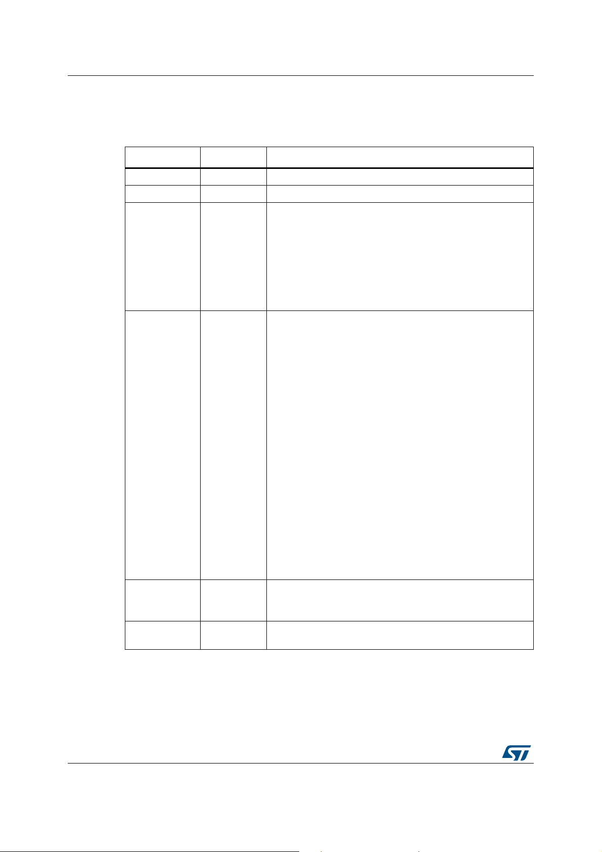
Revision history UM2269
10 Revision history
Date Revision Changes
23-Oct-2017 1 Initial release.
31-Oct-2017 2 Updated Introduction in cover page, Section 1: Boards overview
17-Jan-2018 3
03-Jan-2020 4
Table 52. Document revision history
Updated Table 1: List summary as displayed by firmware when
entering command “help”
Added note on Section 2.2: Controlled by host mode with
commands sent by a COM port terminal, note on Section 2.3:
Controlled by host mode with commands sent by a GUI,
Table 22: “pwr” command, Section : Metadata: Power to target
connection, Section : Metadata: Acknowledge and data of
command “pwr get”, note on Section 9.2.3: Host driver USB-VCP
installation issue
Updated:
– Introduction
– Section 1: Boards overview, Section 2.1: Standalone mode,
Section 5.1.1: Pre-processing: acquisition of raw data from
ADC, Section 6: PowerShield acquisition mode static
characteristics, Section 8: Firmware upgrade
– title of: Section 1.1: PowerShield standalone board X-
NUCLEO-LPM01A, Section 1.2: Quick setup to measure
current on board Nucleo64 with standalone board X-NUCLEOLPM01A, Table 38: Metadata error, Table 39: Metadata
information, Table 40: Metadata timestamp, Table 41: Metadata
end of acquisition, Table 43: Metadata target power down,
Table 44: Metadada Acknowledge and data command “voltage
get”, Table 45: Metadata temperature, Table 46: Metadata
power to target connection, Table 47: Example of data stream
in format 2: Binary, hexadecimal basis
– Table 1: List summary as displayed by firmware when entering
command “help”, Table 10: “lcd” command, Table 15:
“acqmode” command
– Figure 9: Acquisition range and frequency
Added Section 1.3: STM32L5 discovery board
STM32L562E-DK, Metadata: Overcurrent
Updated Section 8: Firmware upgrade
14-May-2020 5
28-Oct-2020 6
58/59 UM2269 Rev 6
Added Figure 11: Firmware upgrade using software
STM32CubeProgrammer
Replaced STM320803 with STM32080 in Section 8: Firmware
upgrade
Page 59

UM2269
IMPORTANT NOTICE – PLEASE READ CAREFULLY
STMicroelectronics NV and its subsidiaries (“ST”) reserve the right to make changes, corrections, enhancements, modifications, and
improvements to ST products and/or to this document at any time without notice. Purchasers should obtain the latest relevant information on
ST products before placing orders. ST products are sold pursuant to ST’s terms and conditions of sale in place at the time of order
acknowledgement.
Purchasers are solely responsible for the choice, selection, and use of ST products and ST assumes no liability for application assistance or
the design of Purchasers’ products.
No license, express or implied, to any intellectual property right is granted by ST herein.
Resale of ST products with provisions different from the information set forth herein shall void any warranty granted by ST for such product.
ST and the ST logo are trademarks of ST. For additional information about ST trademarks, please refer to www.st.com/trademarks. All other
product or service names are the property of their respective owners.
Information in this document supersedes and replaces information previously supplied in any prior versions of this document.
© 2020 STMicroelectronics – All rights reserved
UM2269 Rev 6 59/59
59
 Loading...