

STMicroelectronics ULN200xA, ULN200xD1 Technical data
Features
■ Seven darlingtons per package
■ Output current 500 mA per driver (600 mA
peak)
■ Output voltage 50 V
■ Integrated suppression diodes for inductive
loads
■ Outputs can be paralleled for higher current
■ TTL/CMOS/PMOS/DTL Compatible inputs
■ Inputs pinned opposite outputs to simplify
layout
ULN200xA
ULN200xD1
Seven darlington array
DIP-16 SO-16
(Narrow)
Description
The ULN2001, ULN2002, ULN2003 and ULN
2004 are high voltage, high current darlington
arrays each containing seven open collector
darlington pairs with common emitters. Each
channel rated at 500 mA and can withstand peak
currents of 600 mA. Suppression diodes are
included for inductive load driving and the inputs
are pinned opposite the outputs to simplify board
layout.
The versions interface to all common logic
families:
– ULN2001 (general purpose, DTL, TTL,
PMOS, CMOS)
– ULN2002 (14-25V PMOS)
– ULN2003 (5V TTL, CMOS)
– ULN2004 (6-15V CMOS, PMOS)
Table 1. Device summary
Order code
These versatile devices are useful for driving a
wide range of loads including solenoids, relays
DC motors, LED displays filament lamps, thermal
printheads and high power buffers.
The ULN2001A/2002A/2003A and 2004A are
supplied in 16 pin plastic DIP packages with a
copper leadframe to reduce thermal resistance.
They are available also in small outline package
(SO-16) as ULN2001D1/2002D1/2003D1/
2004D1.
ULN2001A ULN2001D1013TR
ULN2002A ULN2002D1013TR
ULN2003A ULN2003D1013TR
ULN2004A ULN2004D1013TR
August 2007 Rev. 6 1/14
www.st.com
14

ULN200xA - ULN200xD1
Contents
1 Diagram . . . . . . . . . . . . . . . . . . . . . . . . . . . . . . . . . . . . . . . . . . . . . . . . . . . 3
2 Pin configuration . . . . . . . . . . . . . . . . . . . . . . . . . . . . . . . . . . . . . . . . . . . 4
3 Maximum ratings . . . . . . . . . . . . . . . . . . . . . . . . . . . . . . . . . . . . . . . . . . . . 5
4 Electrical characteristics . . . . . . . . . . . . . . . . . . . . . . . . . . . . . . . . . . . . . 6
5 Test circuits . . . . . . . . . . . . . . . . . . . . . . . . . . . . . . . . . . . . . . . . . . . . . . . . 7
6 Package mechanical data . . . . . . . . . . . . . . . . . . . . . . . . . . . . . . . . . . . . . 9
7 Order code . . . . . . . . . . . . . . . . . . . . . . . . . . . . . . . . . . . . . . . . . . . . . . . 12
8 Revision history . . . . . . . . . . . . . . . . . . . . . . . . . . . . . . . . . . . . . . . . . . . 13
2/14
ULN200xA - ULN200xD1 Diagram
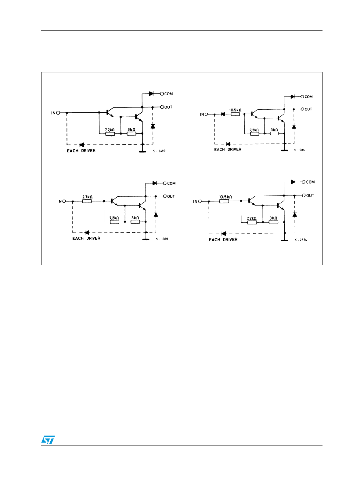
1 Diagram
Figure 1. Schematic diagram
ULN2001 (each driver) ULN2002 (each driver)
ULN2003 (each driver) ULN2004 (each driver)
3/14
Pin configuration ULN200xA - ULN200xD1
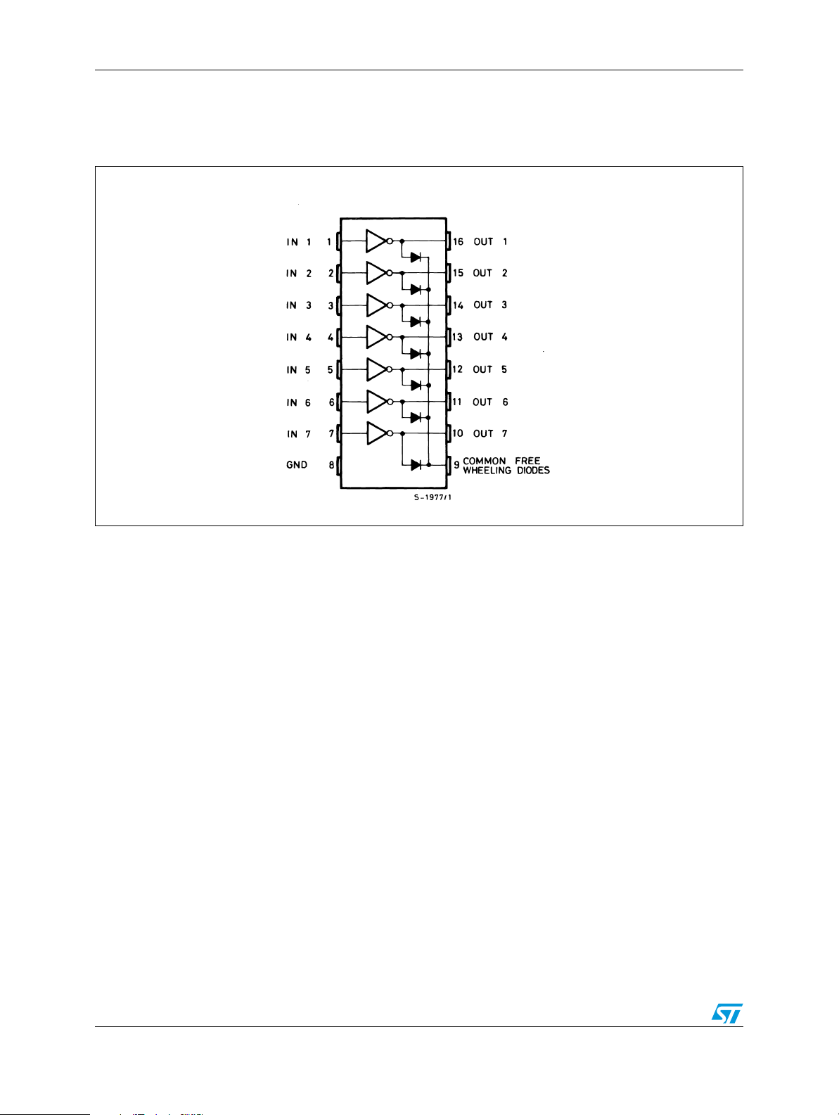
2 Pin configuration
Figure 2. Pin connections (top view)
4/14
ULN200xA - ULN200xD1 Maximum ratings
3 Maximum ratings
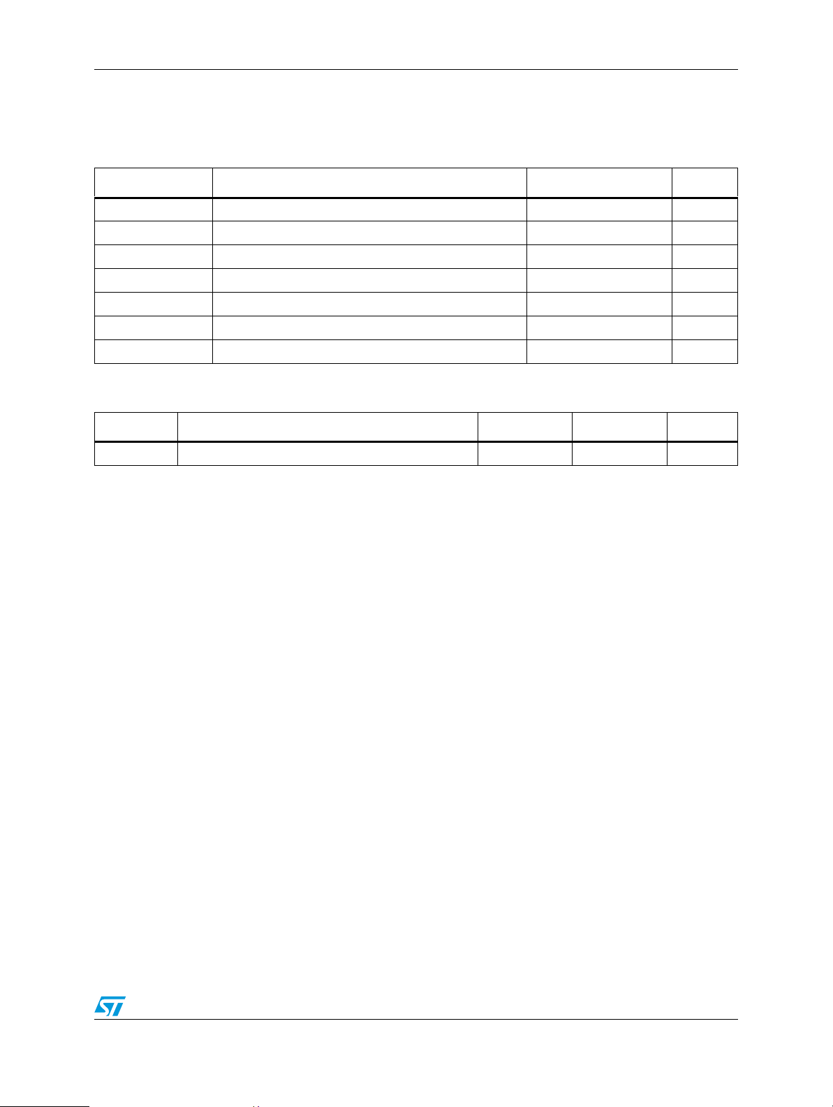
Table 2. Absolute maximum ratings
Symbol Parameter Value Unit
T
V
V
I
C
I
B
T
STG
T
O
I
A
J
Output voltage 50 V
Input voltage (for ULN2002A/D - 2003A/D - 2004A/D) 30 V
Continuous collector current 500 mA
Continuous base current 25 mA
Operating ambient temperature range - 20 to 85 °C
Storage temperature range - 55 to 150 °C
Junction temperature 150 °C
Table 3. Thermal data
Symbol Parameter DIP-16 SO-16 Unit
R
thJA
Thermal resistance junction-ambient, Max. 70 120 ° C/W
5/14
 Loading...