

STMicroelectronics ULN2001A, ULN2002A Technical data
现货库存、技术资料、百科信息、热点资讯,精彩尽在鼎好!
.SEVENDARLINGTONSPERPACKAGE
.OUTPUT CURRENT 500mA PER DRIVER
(600mAPEAK)
.
OUTPUTVOLTAGE50V
.INTEGRAL SUPPRESSION DIODES FOR IN-
DUCTIVELOADS
.OUTPUTS CAN BE PARALLELED FOR
HIGHERCURRENT
.TTL/CMOS/PMOS/DTLCOMPATIBLEINPUTS
.INPUTS PINNED OPPOSITE OUTPUTS TO
SIMPLIFYLAYOUT
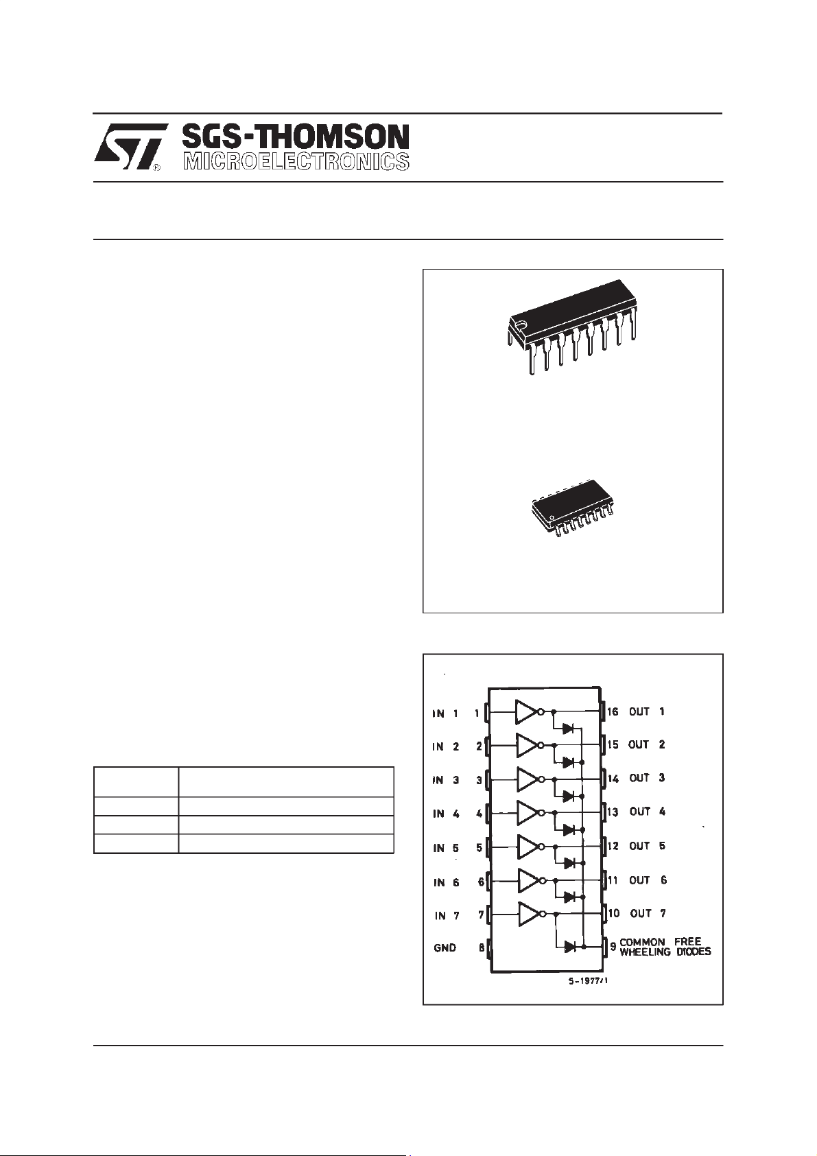
ULN2001A-ULN2002A
ULN2003A-ULN2004A
SEVENDARLINGTONARRAYS
DIP16
ORDERING NUMBERS: ULN2001A/2A/3A/4A
DESCRIP TION
The ULN2001A, ULN2002A, ULN2003 and
ULN2004Aarehighvoltage,highcurrentdarlington
arrays each containing seven open collector darlingtonpairswithcommonemitters.Eachchannelis
ratedat 500mAand can withstandpeakcurrentsof
600mA.Suppressiondiodesareincludedforinductiveload driving and the inputsare pinnedopposite
theoutputsto simplifyboardlayout.
Thefourversionsinterfacetoallcommonlogicfamilies:
ULN2001A General Purpose, DTL, TTL, PMOS,
CMOS
ULN2002A 14-25V PMOS
ULN2003A 5V TTL, CMOS
ULN2004A 6–15V CMOS, PMOS
Theseversatiledevicesareusefulfor drivinga wide
rangeof loads including solenoids,relays DC motors, LED displays filament lamps, thermal printheadsand highpowerbuffers.
TheULN2001A/2002A/2003Aand 2004A are suppliedin 16 pin plastic DIP packageswith a copper
leadframe to reduce thermal resistance. They are
availablealso in smalloutline package(SO-16) as
ULN2001D/2002D/2003D/2004D.
SO16
ORDERING NUMBERS: ULN2001D/2D/3D/4D
PIN CONNE C TI O N
December1997
1/8
ULN2001A - ULN2002A - ULN2003A - ULN2004A
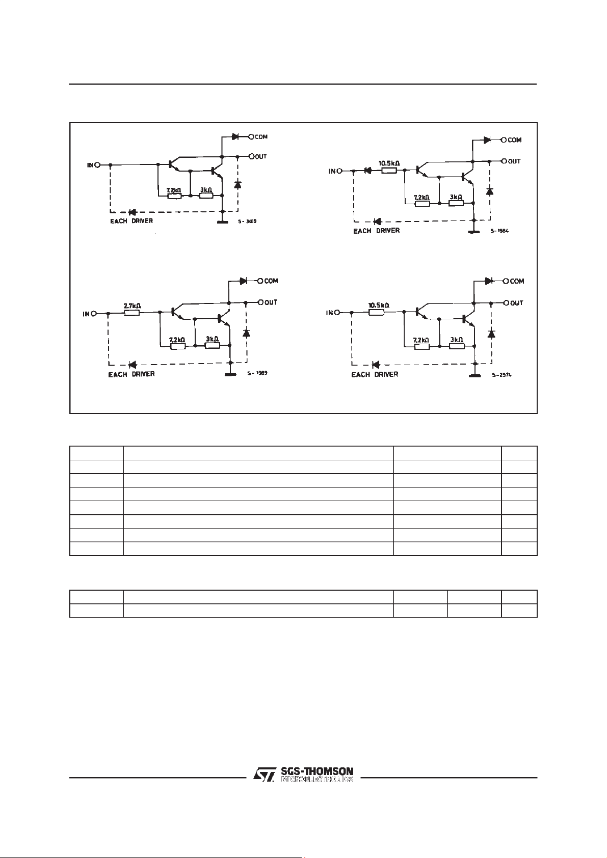
SCHEMATIC DIAG RAM
SeriesULN-2001A
(each driver)
SeriesULN-2003A
(each driver)
SeriesULN-2002A
(each driver)
SeriesULN-2004A
(each driver)
ABSOLUTE MAXIMUM RATINGS
Symbol arameter Value Unit
V
o
V
in
I
c
I
b
T
amb
T
stg
T
Output Voltage 50 V
Input Voltage (for ULN2002A/D - 2003A/D - 2004A/D) 30 V
Continuous Collector Current 500 mA
Continuous Base Current 25 mA
Operating Ambient Temperature Range – 20 to 85
Storage Temperature Range – 55 to 150 °C
Junction Temperature 150
j
C
°
C
°
THERMAL DATA
Symbol Parameter DIP16 SO16 Unit
Thermal Resistance Junction-ambient Max. 70 100 °C/W
2/8
R
th j-amb
ULN2001A - ULN2002A - ULN2003A - ULN2004A
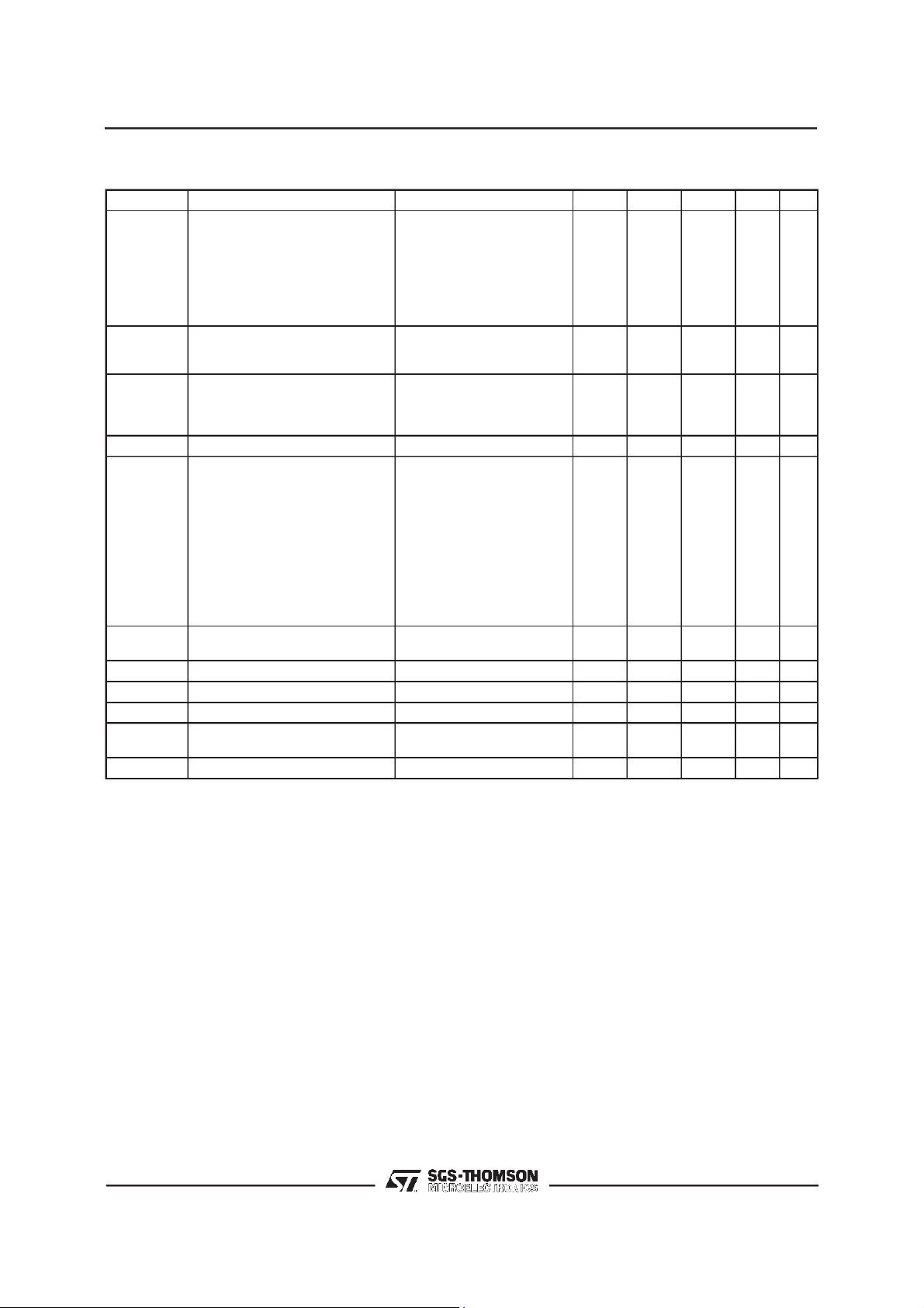
ELECTRICAL CHARACTERISTICS
=25oC unless otherwisespecified)
(T
amb
Symbol Parameter Test Conditions Min. Typ. Max. Unit Fig.
I
CEX
V
CE(sat)
I
i(on)
I
i(off)
V
i(on)
h
FE
C
t
PLH
t
PHL
I
V
R
F
Output Leakage Current VCE= 50V
=70°C, VCE= 50V
T
amb
T
=70°C
amb
Collector-emitter Saturation
Voltage
for ULN2002A
for ULN2004A
IC= 100mA, IB= 250µA
I
I
= 50V, Vi=6V
V
CE
= 50V, Vi=1V
V
CE
= 200 mA, IB= 350µA
C
= 350mA, IB= 500µA
C
Input Current for ULN2002A, Vi= 17V
= 3.85V
i
=5V
i
Input Current T
for ULN2003A, V
for ULN2004A, V
= 12V
V
i
=70°C, IC= 500µA5065
amb
0.9
1.1
1.3
0.82
0.93
0.35
1
100
500
500
1.25
1.35
1.45
Input Voltage VCE=2V
for ULN2002A
= 300mA
I
C
for ULN2003A
= 200mA
I
C
= 250mA
I
C
= 300mA
I
C
for ULN2004A
= 125mA
I
C
= 200mA
I
C
= 275mA
I
C
= 350mA
I
C
DC Forward Current Gain for ULN2001A
= 2V, IC= 350mA 1000 2
V
CE
Input Capacitance 15 25 pF
i
Turn-on Delay Time 0.5 Vito 0.5 V
Turn-off Delay Time 0.5 Vito 0.5 V
o
o
0.25 1 µs
0.25 1
Clamp Diode Leakage Current VR= 50V
=70°C, VR= 50V
T
amb
100
Clamp Diode Forward Voltage IF= 350mA 1.7 2 V 7
50
1.1
1.3
1.6
0.5
13
2.4
2.7
3
5
6
7
8
50
µA
A
µ
A
µ
A
µ
V
V
V
mA
mA
mA
mA
A4
µ
V5
s
µ
A
µ
A66
µ
1a
1a
1b
1b
2
2
2
3
3
3
3
3/8
 Loading...