

Page 1
TELEFUNKEN Semiconductors
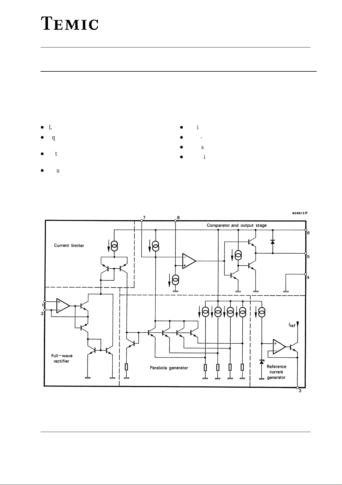
TDA8145
TV East/West Correction Circuit for Square Tubes
Technology: Bipolar
Features
D
D
Low dissipation
D
Square generator for parabolic current specially designed for square C.R.T. correction
D
External keystone adjustment (symmetry of the parabola)
D
Input for dynamic field correction (beam current
change)
Case: 8 pin dual inline plastic
Static picture width adjustment
D
Pulse-width modulator
D
Final stage D-class with energy redelivery
D
Parasitic parabola suppression, during flyback time of
the vertical sawtooth
Figure 1. Block diagram
Rev . A1: 13.04.1995 1 (4)
Page 2

TDA8145
V
7A
V
7C
%
Absolute Maximum Ratings
Parameters Symbol Value Unit
Supply voltage Pin 6 V
Supply current Pin 6 I
Power dissipation T
Storage temperature range T
Junction temperature T
Electrical Characteristics
V
= 26 V, T
S
Supply voltage Pin 6 V
Supply current Test circuit 1 Pin 6 I
Reference voltage Test circuit 1 Pin 3 V
Voltage at Pin 7 * Test circuit figure 2, Pin 7
Parabola coefficient
Difference, figure 2
Current source Test circuit 3 Pin 8 I
Saturation voltage I
Forward voltage I
= 25°C, Test circuits 1 to 5
amb
Parameters Test Conditions / Pins Symbol Min. Typ. Max. Unit
= 50°C P
case
I
= 0 mA
fr
I
= 30 mA
fr
V
*
V
K1+
K2+
V
+
V7E*
DE7
= 400 mA, Pin 5
5
7A
V7A*
V7A*
V7A*
V
7F
V
V
V
Test circuit 4
I
= –100 mA, Pin 5
5
Test circuit 5
= 400 mA, Pin 5
5
Test circuit 5
V
V
7B
7
7C
7D
V
V
satL
satH
V
S
ref
7A
7C
8
TELEFUNKEN Semiconductors
S
S
tot
stg
j
S
17 24 30 V
7.6 8.0 8.8 V
15.3
–40 0 40 mV
F
35 V
500 mA
500 mW
–25 to 150 °C
–25 to 150 °C
4.5 7 mA
16.0
16.7 V
15.0
26
70
100
1
0.8
2
1.5
1.2 1.7 V
93 7666
%
m
A
V
V
V
7
V
7A
V
7B
V
7C
V
V
7E
7D
–60 0 10 20 35 60 mA
Figure 2. Parabola coefficients
V
7F
I
FR
Rev . A1: 13.04.19952 (4)
Page 3

TELEFUNKEN Semiconductors
Figure 3. Test circuit 1 Figure 4. Test circuit 2
TDA8145
Figure 5. Test circuit 3 Figure 6. Test circuit 4
Figure 7. Test circuit 5
Rev . A1: 13.04.1995 3 (4)
Page 4

TDA8145
Dimensions in mm
Package: DIP 8
TELEFUNKEN Semiconductors
94 8873
We reserve the right to make changes to improve technical design and may do so without further notice.
Parameters can vary in different applications. All operating parameters must be validated for each customer
application by the customer. Should the buyer use TEMIC products for any unintended or unauthorized
application, the buyer shall indemnify TEMIC against all claims, costs, damages, and expenses, arising out of,
directly or indirectly, any claim of personal damage, injury or death associated with such unintended or
unauthorized use.
TEMIC TELEFUNKEN microelectronic GmbH, P.O.B. 3535, D-74025 Heilbronn, Germany
Telephone: 49 (0)7131 67 2831, Fax number: 49 (0)7131 67 2423
Rev . A1: 13.04.19954 (4)
 Loading...