

Page 1
STM32MP157C-DK2 rev. C01
STEVAL-IDP004V1
sensor nodes
STEVAL-BFA001V1B
IoT Cloud Application
AWS IoT Greengrass
Serial
Interface
WireST
SDK
EdgeST
SDK
PredMnt application
X-LINUX-PREDMNT
DSH-PREDMNT dashboard
Predictive Maintenance
Cloud application
UM2639
User manual
How to use the STM32 MPU OpenSTLinux Expansion Pack for Predictive
Maintenance
Introduction
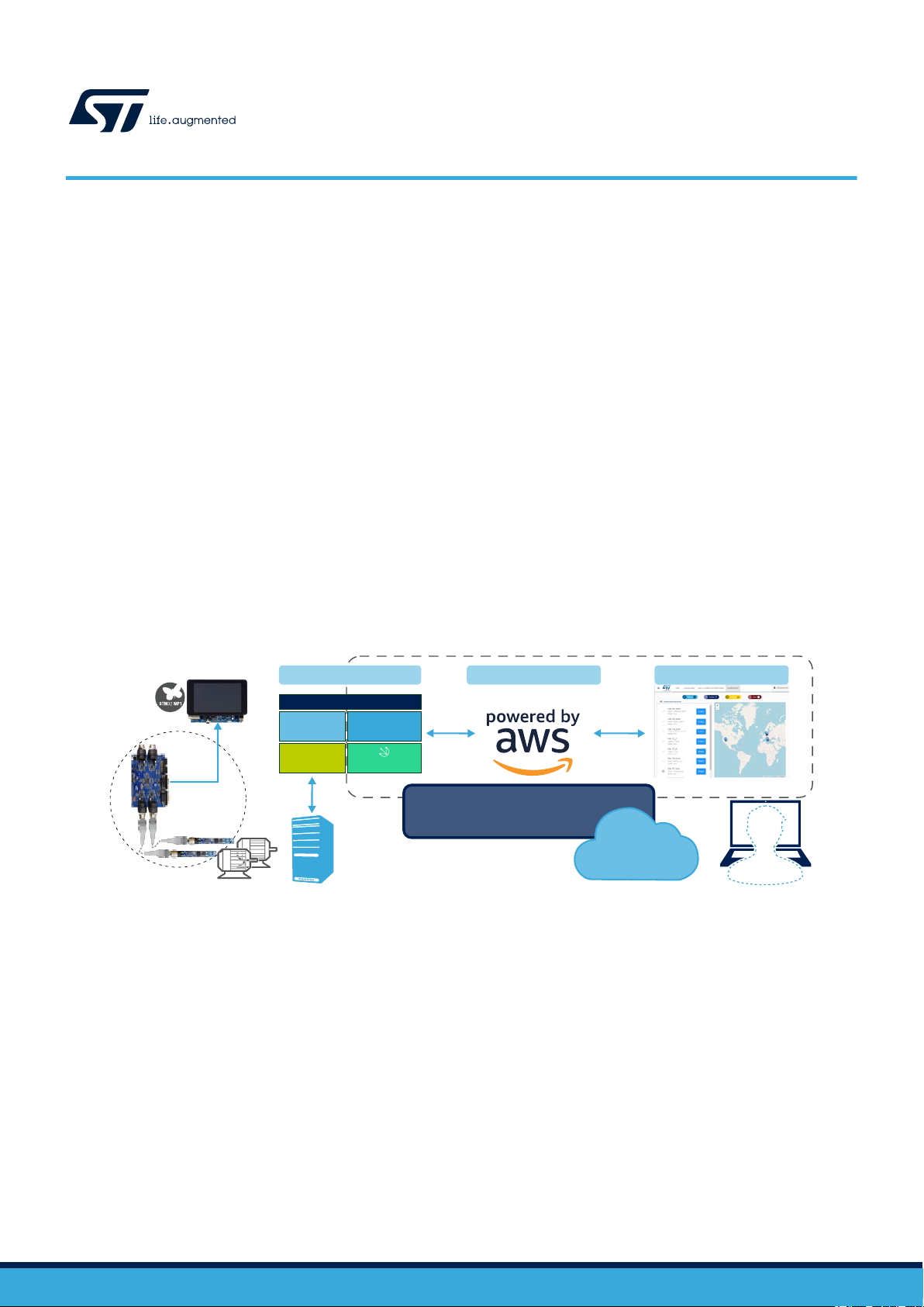
The STM32 MPU OpenSTLinux Expansion Pack for Predictive Maintenance enables the development of Edge processing
applications. It forms an end-to-end solution with corresponding hardware to allow environmental and inertial data from
industrial equipment to be sent to an IoT application with dedicated dashboard for data analysis and identification of conditions
that might require immediate or future maintenance intervention.
The application helps users manage many of the critical aspects of ef
such as registering remote devices, configuring gateways, and connecting to IoT cloud services. In particular, it interfaces with
the Amazon AWS IoT cloud and uses the AWS IoT Greengrass Edge Computing service on the gateway to run local logic and
transmit data seamlessly, even under conditions of intermittent Internet connectivity.
The development hardware for the application includes a vibration kit with motors, STEVAL-BFA001V1B IO-Link sensor boards
with inertial measurement unit, various environmental sensors plus on-board MCU for sensor data computation and
management, and the STEVAL-IDP004V1 IO-Link master board. A gateway node is set up with the STM32MP157C-DK2
Discovery board featuring various wired and wireless connectivity solutions, SD card data storage, LCD touch screen interface
and appropriate high performance STM32MP1 Series microprocessor.
The edge gateway collects environmental and FFT data from accelerometer sensors, which are then sent via MQTT over
Ethernet or Wi-Fi to a dashboard based on the AWS infrastructure.
fective condition monitoring with remote IoT sensor nodes,
Figure 1. Condition monitoring and Edge to Cloud: from sensors to gateway to cloud dashboard
UM2639 - Rev 3 - September 2020
For further information contact your local STMicroelectronics sales of
fice.
www.st.com
Page 2
1 Edge processing application overview
For the edge processing application setup, you need the following elements:
•
Gateway node:
– STM32MP157C-DK2 Discovery board with a minimum 4GB SD card
• Smart sensors and Master hardware:
– master board: STEVAL-IDP004V1
– sensor boards: STEVAL-BFA001V1B kit
• myST.com account for the Edge Processing Application dashboard.
• PC with the STM32 ST-LINK Utility and ST-LINK Programmer (standalone or integrated in STM32 Nucleo
boards).
• Internet connection with no proxy nor firewall.
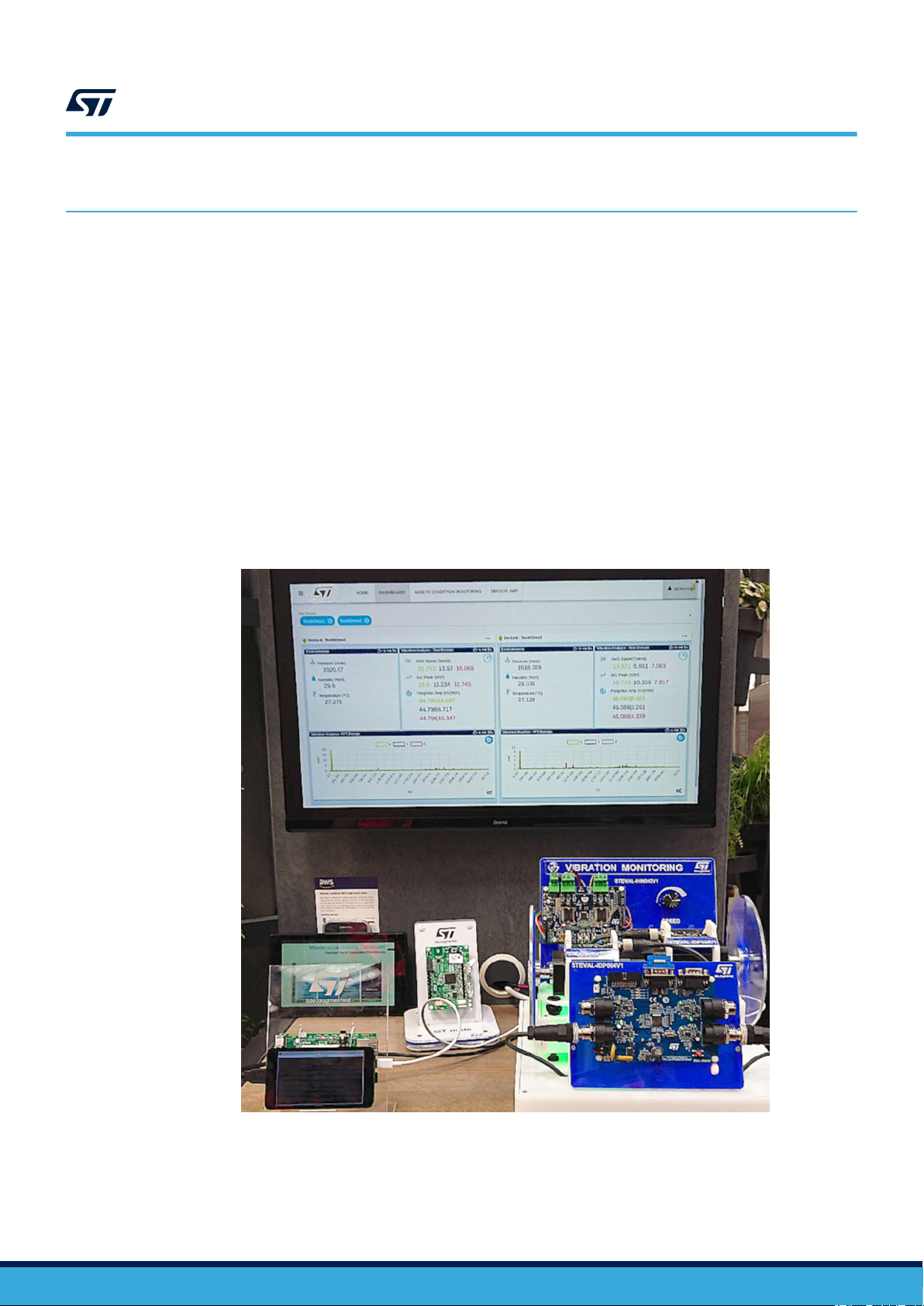
The figure below shows a demo which integrates all the components required to monitor two motors that can be
driven at different speeds. The two motors can be balanced with different weights, and the dashboard shows the
time, environmental and frequency data of both, allowing the observer to easily identify which motor is not
performing appropriately.
UM2639
Edge processing application overview
Figure 2. Integrated demo with smart sensor nodes installed on two motors
UM2639 - Rev 3
page 2/31
Page 3
DEPLOY
END
GATEWAY
(2)
GATEWAY
START
VISUALIZE DATA
Gateway
GREENGRASS
START
THE EDGE GATEWAY
INSTALL
EDGE GATEWAY
ASSIGN DEVICES TO
GREENGRASS
CONFIGURE THE
VIBRATION SETUP
STOP
THE APPLICATION
DEACTIVATE
REGISTER
IOT DEVICES
REGISTER AN
CREDENTIALS
Vibration setup Dashboard
DEVICE
(3.2)
PROVISIONING
INSTALL
CREDENTIALS
(3.3)
(4)
DEPLOYMENT
APPLICATION
START
(5)
CONDITION
MONITORING
(6)
STOP
APPLICATION
Legenda
BEGIN
MASTERBOARD
INSTALL
(3) APPLICATION SETUP
FLASH THE
STOP THE
ST SDKS
SENSORS
GREENGRASS
INSTALL
(3.1)
VIBRATION SETUP
SETUP
(1)
SENSORS AND
MASTERBOARD SETUP
APPLICATION
ACTIVATE
FLASH THE
START
GREENGRASS
Edge Processing Application setup and operation
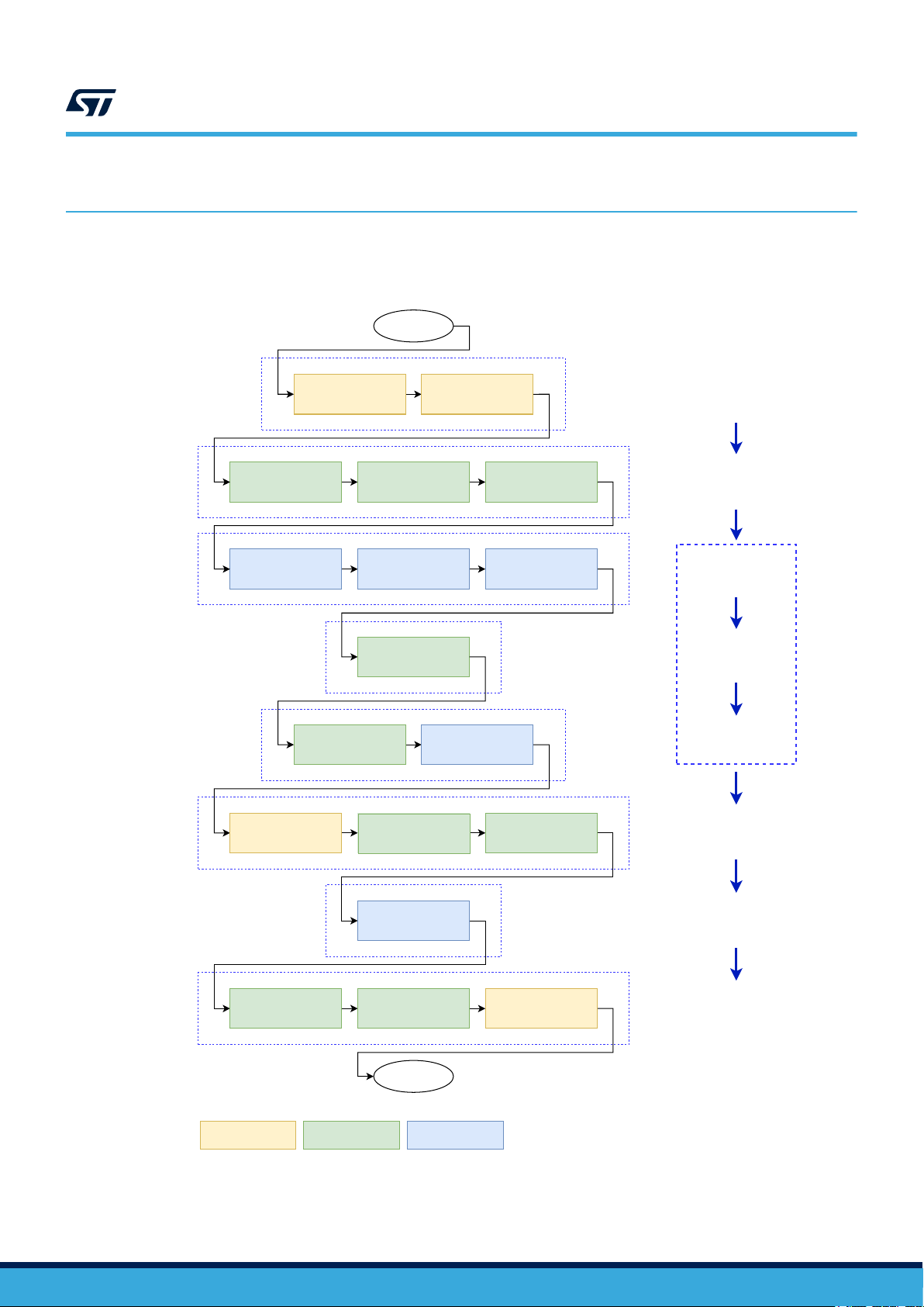
2 Edge Processing Application setup and operation
The flow chart below provides an overview of the procedure involved in setting up and running the application.
Figure 3. Setup and operation
UM2639
UM2639 - Rev 3
page 3/31
Page 4
2.1 Sensor and master board setup
Follow the procedure below to flash the sensor board and the master board with the latest firmware.
Step 1. Download the binary files for the sensor and master boards from the following locations on the ST
website:
–
Sensor node: STSW-BFA001V1
– Master board: STSW-IDP4PREDMNT
Step 2. Flash the relevant binaries onto the STEVAL-IDP004V1 IO-Link master board and STEVAL-
BFA001V1B IO-Link sensor boards.
Use the STM32 ST-LINK (STSW-LINK004) Utility and an appropriate ST-LINK programmer/debugger
device (standalone or integrated in STM32 Nucleo boards).
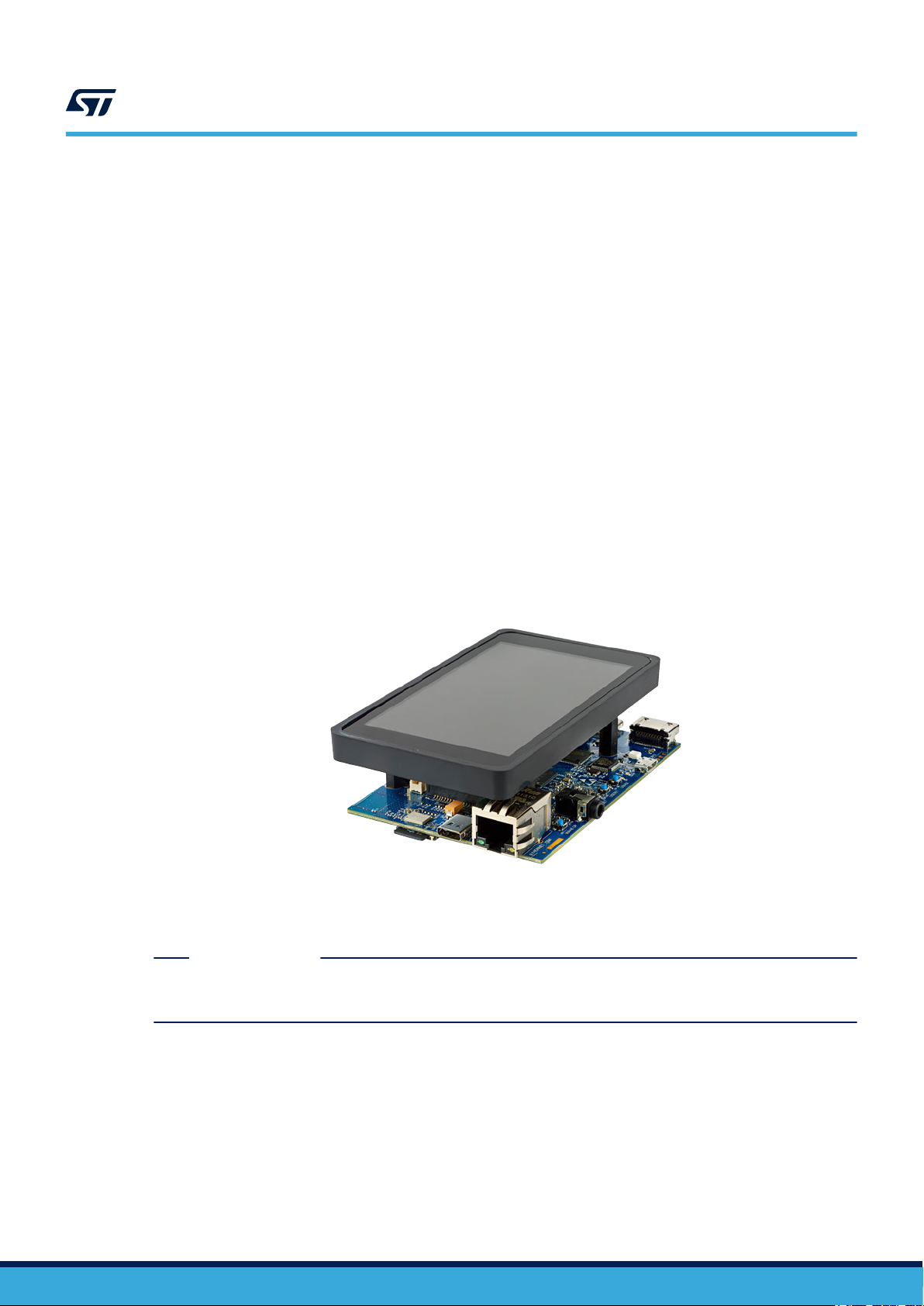
2.2 Gateway setup
To set up an STM32MP157C-DK2 Discovery kit as the Edge gateway for your Predictive Maintenance Platform,
you can either:
•
Flash a pre-configured image by ST:
– X-LINUX-PREDMNT
• Create and flash a custom image
UM2639
Sensor and master board setup
Figure 4. STM32MP157C-DK2 Discovery kit
STM32 MPU with dual-core Cortex-A7 CPU, 533 MHz GPU and Cortex-M4 MCU
Secure Boot and cryptography, LCD, Wi-Fi, Bluetooth Low Energy
Important: Set the micro-switches to OFF before flashing and to ON just after.
RELATED LINKS
You can use this free tool to master your binary images onto an SD card
isit the STM32 MPU wiki page for relevant guides and resources regarding the STM32 MPU
V
UM2639 - Rev 3
page 4/31
Page 5

2.2.1 How to create an image for the STM32MP1 Discovery kit
Follow the instructions below to configure an STM32MP157C-DK2 Discovery kit as a Linux gateway
Note: The instructions apply to the STM32MP1 DK2 C01 and C2 releases only.
Step 1. Set up your host environment according to the PC prerequisites page at the STM32 MPU wiki page:
https://wiki.st.com/stm32mpu/wiki/PC_prerequisites
Step 2. If this is the first use of the Discovery board, install the Starter Package and flash the image to an
empty SD card so that all the partitions are created:
https://wiki.st.com/stm32mpu/wiki/STM32MP15_Discovery_kits_-_Starter_Package
Important: Set the micro-switches to OFF before flashing and to ON just after.
Step 3. Get the distribution package as described in the following wiki page:
https://wiki.st.com/stm32mpu/wiki/STM32MP1_Distribution_Package
Step 4. Follow the instructions up to and including the command to build the image:
bitbake st-image-weston
The image file is included in the distribution package.
UM2639
Gateway setup
.
Step 5. Move to the <layers> directory and install the meta-predmnt layer
, available here:
https://github.com/STMicroelectronics/meta-predmnt
This layer contains the recipes to install the Predictive Maintenance application, the Amazon AWS IoT
Greengrass service for edge computing (https://aws.amazon.com/it/greengrass/), and other required
Python packages (view meta-predmnt/conf/layer.conf file for further details):
cd <path-to>/openstlinux-<version>/layers
git clone https://github.com/STMicroelectronics/meta-predmnt
cd <path-to>/openstlinux-<version>/build-openstlinuxweston-stm32mp1/conf/
Step 6. Copy and paste the following line into the bblayers.conf file, just before the BBLA
definition, and check that the BBLAYERS token contains the FRAMEWORKLAYERS token, otherwise
add it:
FRAMEWORKLAYERS += "${@'${OEROOT}/layers/meta-predmnt' if os.path.isfile('${OEROOT}/
layers/meta-predmnt/conf/layer.conf') else ''}"
YERS token
UM2639 - Rev 3
page 5/31
Page 6

UM2639
Gateway setup
Step 7. Move to the <openstlinux> directory
cd <path-to>/openstlinux-<version>
bitbake virtual/kernel -c menuconfig
Step 7a. Navigate to [Device Drivers] and to [USB support].
Step 7b. Place a check on the following entry by pressing the
character appears and then press enter:
USB Serial Converter support
Step 7c. Place a check on the following entries by pressing the
character appears and then press enter:
USB Serial Console device support
USB Generic Serial Driver
USB Serial Simple Driver
USB FTDI Single Port Serial Driver
Step 7d. Save and exit:
, enable the USB support in the kernel, and build:
[Space] key until an asterix (*)
[Space] key until an asterix (*)
bitbake virtual/kernel
Step 8. Move to the <openstlinux> directory
, and build the image (same instructions described in the
Distribution Package page):
cd <path-to>/openstlinux-<version>
DISTRO=openstlinux-weston MACHINE=stm32mp1 source layers/meta-st/scripts/envsetup.sh
bitbake st-image-weston
Step 9. Move to the <image> directory
, and flash the image (same instructions described in the Starter
Package page):
Important: Set the micro-switches to OFF before flashing and to ON just after.
cd <path-to>/openstlinux-<version>/build-openstlinuxweston-stm32mp1/tmp-glibc/
deploy/images/stm32mp1
STM32_Programmer_CLI -c port=usb1 -w flashlayout_st-image-weston/
FlashLayout_sdcard_stm32mp157c-dk2-trusted.tsv
UM2639 - Rev 3
page 6/31
Page 7
2.2.2 How to configure the gateway
Important: Set the micro-switches to ON before turning the gateway on.
UM2639
Gateway setup
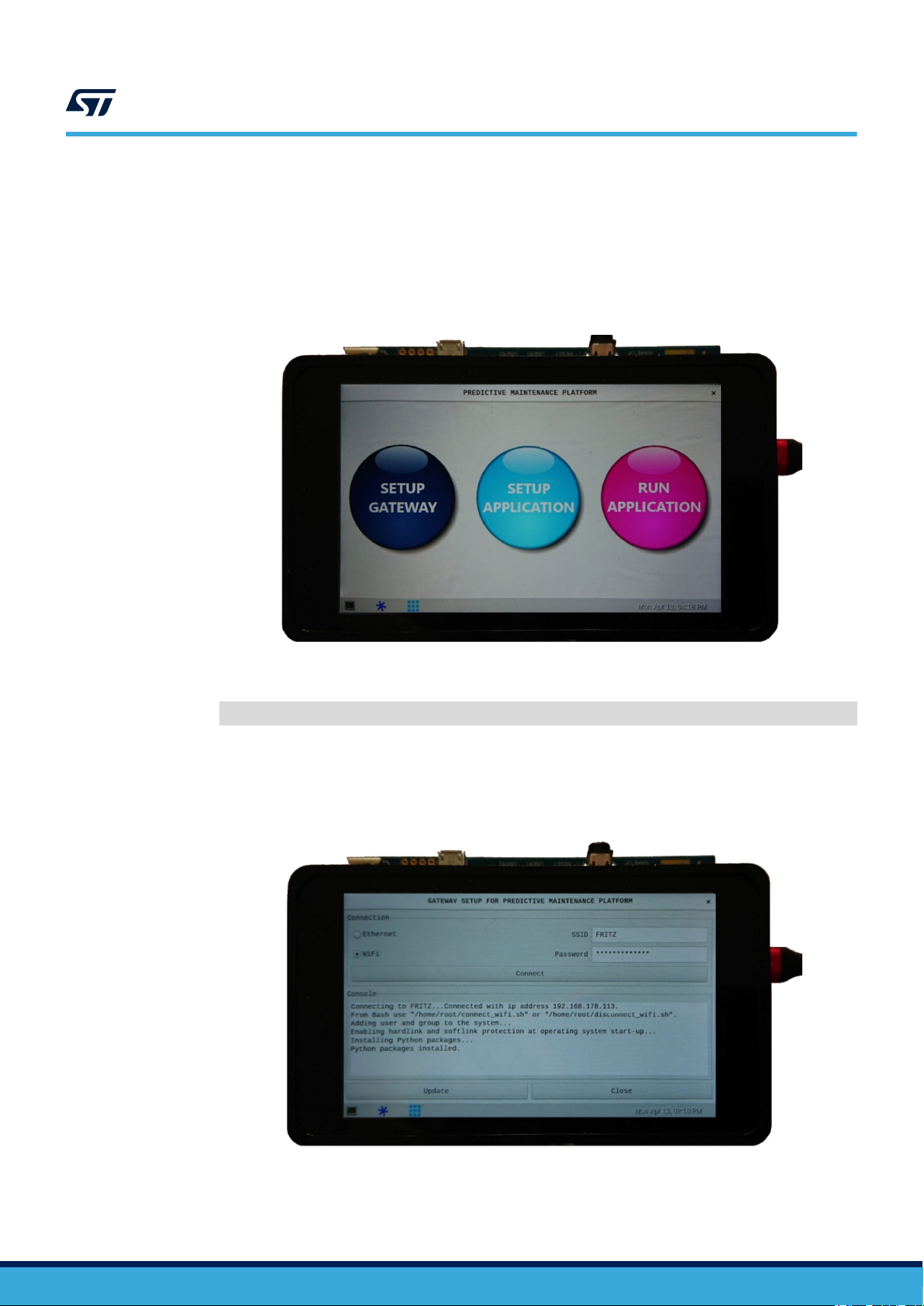
Step 1. Turn the gateway ON and wait for the Main GUI to appear
Figure 5. Gateway Main GUI
The Main GUI can also be started via the following command:
/home/root/start_pmp.sh --gui
.
Step 2. Complete the gateway setup by clicking on the [SETUP GATEWAY] button .
The following panel appears to allow you configure and connect the gateway to a Wi-Fi network or to
the Internet through an Ethernet cable.
Figure 6. Gateway GUI setup
UM2639 - Rev 3
page 7/31
Page 8

Step 3. Click on the [Update] button to install or update the following libraries:
–
Amazon AWS IoT Python SDK: https://github.com/aws/aws-iot-device-sdk-python
– WireSTSDK: https://github.com/STMicroelectronics/WireSTSDK_Python
– EdgeSTSDK: https://github.com/STMicroelectronics/EdgeSTSDK_Python
– Other Python packages (pyserial, futures, enum34)
2.2.3 How to connect to the gateway via SSH
Once the gateway is connected to a network:
Step 1. Retrieve its IP address from a terminal on the gateway with the command below:
ifconfig
Step 2. Connect to the gateway from another device via SSH by running the following command (you have to
use “root” for the user on the “openstlinux” distribution):
ssh <user>@<IP-ADDRESS>
2.2.4 How to reboot and turn the gateway off
Step 1. T
o reboot the gateway, run the following command as super user:
UM2639
Gateway setup
Step 2. T
reboot
o safely turn the gateway off, run the following command as super user:
shutdown 0
UM2639 - Rev 3
page 8/31
Page 9
2.3 Application setup
UM2639
Application setup
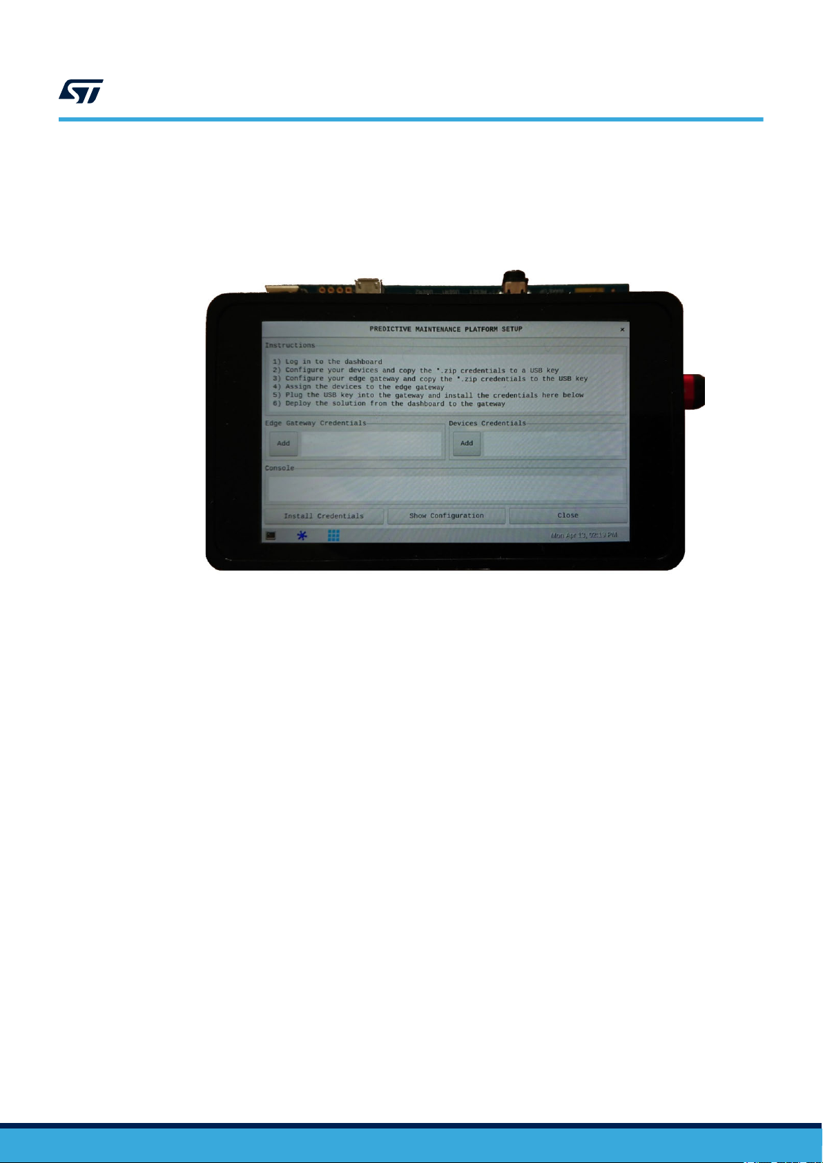
From the Main GUI, click on the [SETUP APPLICA
procedure.
Figure 7. GUI application setup
TION] button (see Figure 5) to start the guided configuration
Step 1. Log in to the dashboard.
Step 2. Configure your devices and copy the *.zip credentials to a USB key
Step 3. Configure your edge gateway and copy the *.zip credentials to the USB key.
Step 4. Assign the devices to the edge gateway.
Step 5. Plug the USB key into the gateway and install the credentials.
Step 6. Deploy the solution from the dashboard to the gateway.
.
UM2639 - Rev 3
page 9/31
Page 10

2.3.1 Log in to the dashboard
Important: You need a valid myST.com account to launch the dashboard and register devices.
UM2639
Application setup
Step 1. Open the dashboard and log in with myST
– https://dsh-predmnt.st.com/
2.3.2 How to configure devices
Step 1. Click on [Register a new device] and then on [DEVICES] panel.
Step 2. Click [Add Device] and register two devices with an appropriate name and optional information.
.com credentials:
Figure 8. Predictive Maintenance Platform main screen
Figure 9. Add Device page
UM2639 - Rev 3
page 10/31
Page 11

UM2639
Application setup
Step 3. Download the corresponding zip file (containing certificate and key) before closing the popup window
and copy it to the root of a USB key
.
Figure 10. Download configuration files
2.3.3 How to configure an edge gateway
Step 1. Go to the
Step 2. Click [Add Device] and register an edge gateway with an appropriate name.
Step 3. Download the corresponding zip file (certificate and key credentials) before closing the popup window
and copy it to the root of the USB key previously used.
[EDGE GATEWAYS] dashboard panel.
2.3.4 How to assign devices to an edge gateway
Step 1. From the
Step 2. Select the devices you want to add to the gateway and click [Save].
[EDGE GATEWAYS] dashboard panel, click the [Setting] gear icon and then [Devices].
Figure 12. Assign devices to an edge gateway
Figure 11. Add new edge
UM2639 - Rev 3
page 11/31
Page 12
2.3.5 How to install credentials to the gateway
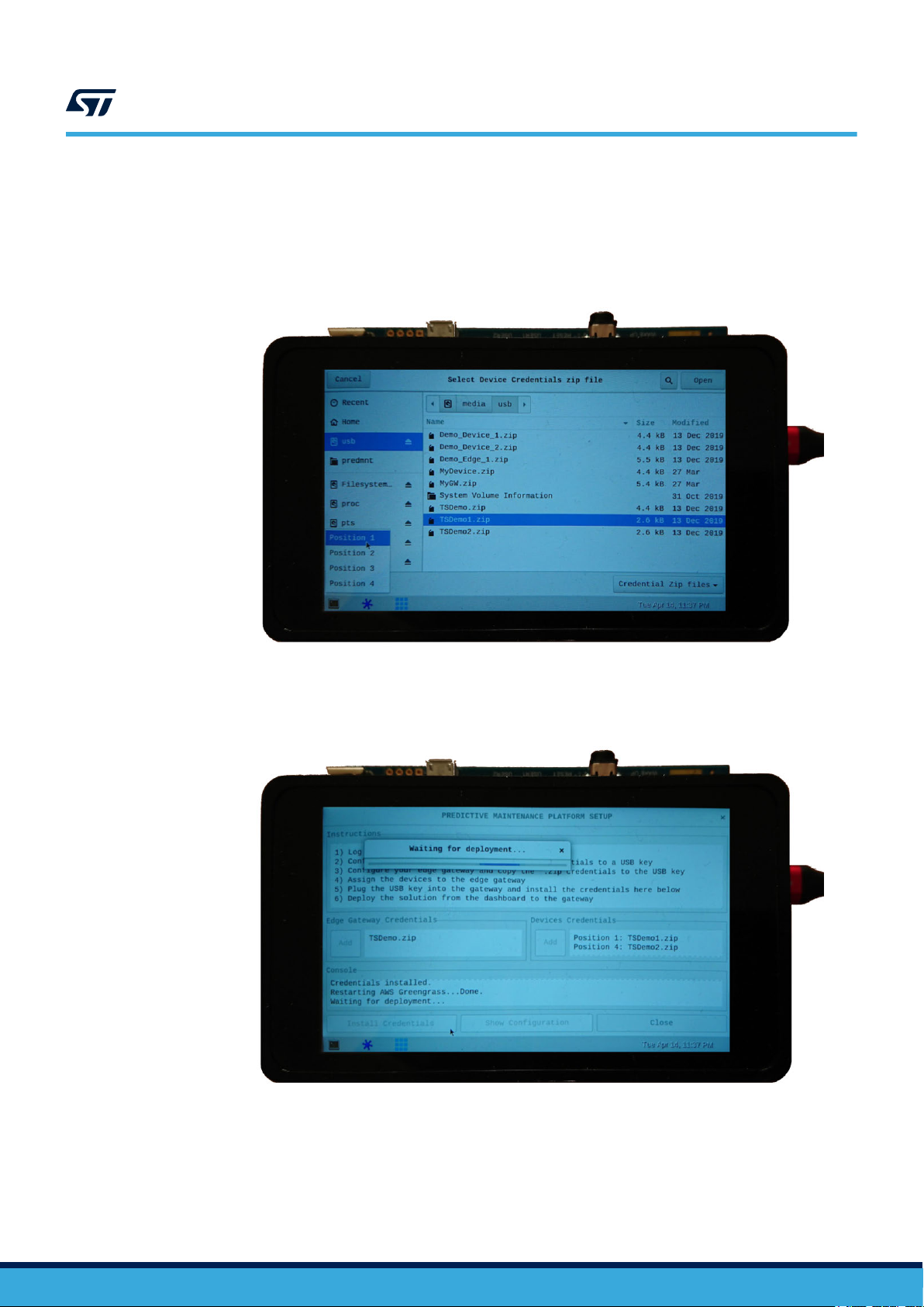
Step 1. Plug the previously used USB key to the gateway and add the gateway credentials and up to four
devices by clicking on the corresponding
Step 2. Select the position of the devices according to the position they have on the masterboard (from 1 to 4).
Figure 13. Assign devices to an edge gateway
UM2639
Application setup
[Add] buttons.
Step 3. Click the [Install Credentials]
The Greengrass daemon is restarted and the gateway waits for deployment from the dashboard.
button to install the credentials on the gateway.
Figure 14. Waiting for deployment
UM2639 - Rev 3
page 12/31
Page 13
2.3.6 How to deploy a solution
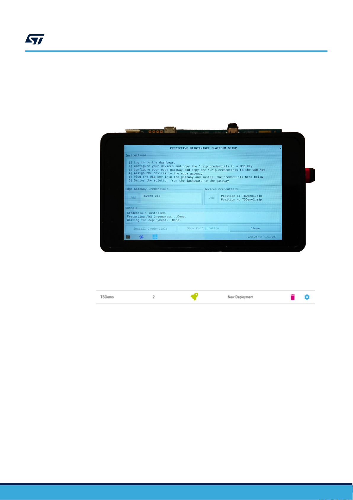
Step 1. Move to the [EDGE GA
and then [CONFIRM].
If the connection is correctly working, after some seconds the deployment successfully completes and
the gateway is configured.
UM2639
Application setup
TEWAYS] panel of the dashboard, click the [Setting] gear icon, select [Deploy]
Figure 15. Deployment successful on the gateway
Step 2. Reload the web page and check whether the status of the “New Deployment” operation has properly
completed (green icon); repeat if necessary.
Figure 16. Deployment successful on the dashboard
UM2639 - Rev 3
page 13/31
Page 14

2.4 Starting the application
2.4.1 How to activate the vibration setup
Step 1. Connect the vibration setup to the gateway via USB cable.
Step 2. Power the vibration setup on.
Step 3. Set the vibration setup speed to the desired value.
2.4.2 How to start the application
Step 1. Start the application:
From the Main GUI, click on the [RUN APPLICATION] button to start the application: a new
–
window pops up showing the output of the underlying application.
– Alternatively, from a terminal, run the following script
/home/root/start_pmp.sh
–
or launch the following commands:
/greengrass/ggc/core/greengrassd restart
◦
UM2639
Starting the application
◦ export PYTHONPATH=$PYTHONPATH:/usr/local/predmnt/
◦ python3 /usr/local/predmnt/pmp.py -c /usr/local/predmnt/pmp.json
UM2639 - Rev 3
page 14/31
Page 15

2.5 Condition Monitoring
2.5.1 Data visualization on the gateway
At application startup, on the gateway:
Greengrass daemon starts.
1.
2. WireST-SDK initializes the masterboard and sensor devices.
Figure 17. Greengrass startup and device initialization
UM2639
Condition Monitoring
3. Greengrass daemon contacts Greengrass core on the cloud through EdgeST
4. Devices and their counterparts on the cloud start communication.
5. The application receives data from the sensors and sends them to the cloud.
Figure 18. Gateway receives data from the sensors
-SDK.
UM2639 - Rev 3
page 15/31
Page 16

UM2639
Condition Monitoring
6. Optional: if the solution deployed from the dashboard contains a Lambda function (depending on the
dashboard implementation) to process data locally (typically a filter on the Fast Fourier T
the vibration data), the alarms triggered are shown on the gateway screen.
Different alarm windows can pop up on the screen and an acoustic alarm is played through the audio jack on
a connected speaker.
Figure 19. Alarm pop-up windows
A. Normal: in case the FFT data are within the normal range
B. Warning: in case FFT data overcome the FFT warning threshold
C. Critical: in case FFT data overcome the FFT critical threshold
Moreover, a colored log of data and alarms is shown.
ransform (FFT) of
Figure 20. Alarm logs
Alarm signals are also sent to the cloud dashboard for further use.
UM2639 - Rev 3
page 16/31
Page 17

2.5.2 Data visualization on the dashboard
Follow the procedure below to view the sensor data on the dashboard.
Step 1. Open the dashboard and log in with myST
https://dsh-predmnt.st.com/
Step 2. Click on [DASHBOARD], then [Add Device] and select the desired devices to monitor.
A panel for each selected device opens and shows the exported data values.
Figure 21. Device panel with sensor data and parameters
UM2639
Condition Monitoring
.com credentials:
Step 3. If needed, it is possible to configure some thresholds for the feature exported by the devices, which can
be useful to quickly check the working condition of the devices through the gauge panel. From the main
page, choose [Register a new device], select a device, click on the
[Settings] gear icon, then on
[Configure Thresholds] and choose a feature from the drop-down menu to configure the desired
thresholds.
Figure 22. Threshold settings for each device
UM2639 - Rev 3
page 17/31
Page 18

UM2639
Condition Monitoring
Step 4. Click on [ASSETS CONDITION MONIT
A gauge panel appears for each selected device showing its working condition according to the last
configured feature.
Figure 23. Gauge panel for each device
ORING].
UM2639 - Rev 3
page 18/31
Page 19

2.6 Stopping the application
2.6.1 How to stop the application
Step 1. T
2.6.2 How to deactivate the vibration setup
Step 1. Set the speed of the vibration setup to zero.
o stop the application:
– From the “RUN APPLICATION” GUI, click on the [Close] button
– Alternatively, press [CTRL+C] on the terminal where the application was launched
– Or, from a different terminal, run the stop script:
/home/root/stop_pmp.sh
UM2639
Stopping the application
Step 2. Power vibration setup of
f.
UM2639 - Rev 3
page 19/31
Page 20
Additional information on gateway application configuration
3 Additional information on gateway application configuration
Additional information, such as edge gateway credentials, Greengrass configuration and configuration of the
application on the gateway
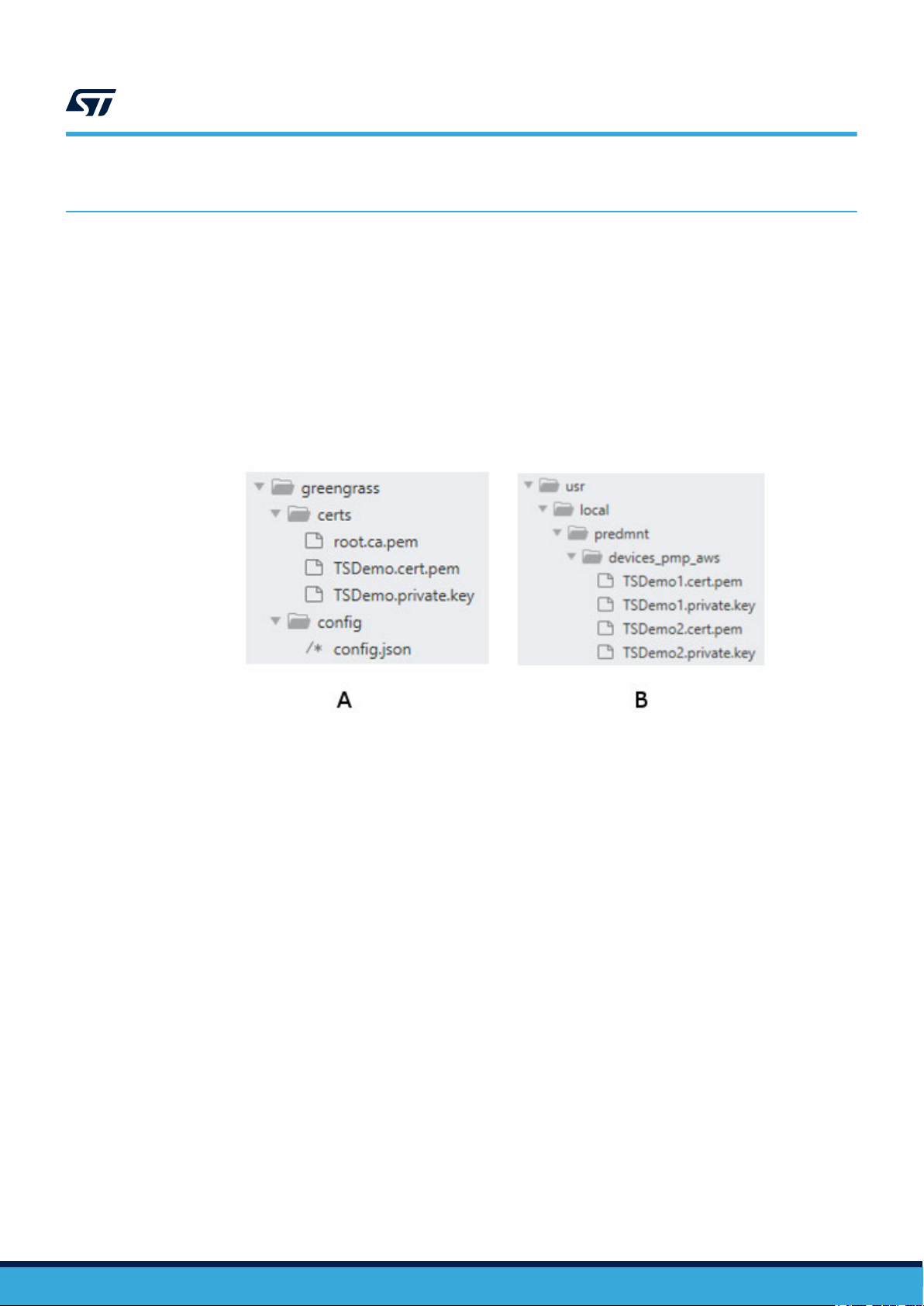
3.1 Credentials
The “/greengrass” folder contains the edge gateway credentials, the Root Certification Authority certificate file
(root.ca.pem) and the Greengrass configuration file (config.json).
The “/usr/local/predmnt/devices_pmp_aws” folder contains the device credentials.
A. Edge gateway credentials
B. Device credentials
, could be useful when developing applications and for debugging issues.
Figure 24. Credentials on the gateway filesystem
UM2639
UM2639 - Rev 3
page 20/31
Page 21

3.2 Greengrass configuration
As soon as the Greengrass daemon starts, the “config.json” file allows it to get information about how to connect
to the Greengrass core of the cloud application.
The code below is an example of configuration file.
{
"coreThing" : {
"caPath" : "root.ca.pem",
"certPath" : "TSDemo.cert.pem",
"keyPath" : "TSDemo.private.key",
"thingArn" : "arn:aws:iot:eu-west-1:982787141379:thing/TSDemo_Core",
"iotHost" : "a1azohj3ky8ktj-ats.iot.eu-west-1.amazonaws.com",
"ggHost" : "greengrass-ats.iot.eu-west-1.amazonaws.com",
"keepAlive" : 600
},
"runtime" : {
"cgroup" : {
"useSystemd" : "yes"
}
},
"managedRespawn" : false,
"crypto" : {
"principals" : {
"SecretsManager" : {
"privateKeyPath": "file:///greengrass/certs/TSDemo.private.key"
},
"IoTCertificate" : {
"privateKeyPath": "file:///greengrass/certs/TSDemo.private.key",
"certificatePath": "file:///greengrass/certs/TSDemo.cert.pem"
}
},
"caPath" : "file:///greengrass/certs/root.ca.pem"
}
}
UM2639
Greengrass configuration
UM2639 - Rev 3
page 21/31
Page 22

3.3 Application configuration
The application user settings are stored in the “/usr/local/predmnt/pmp.json” configuration file.
{
"serial_port": {
"name": "/dev/ttyUSB0",
"baudrate_bits_per_second": 230400
},
"setup": {
"use_sensors": true,
"use_cloud": true,
"use_threads_for_polling_sensors": true,
"device_certificates_path": "/usr/local/predmnt/devices_pmp_aws",
"devices": [
{
"name": "TSDemo1",
"position": 1
},
{
"name": "TSDemo2",
"position": 4
}
]
},
"dump": {
"env_samples": 0,
"tdm_samples": 0,
"fdm_samples": 0
}
}
UM2639
Application configuration
The code above shows an example of application configuration file on the gateway
, containing the following
parameters:
• serial_port: name and baud rate of the serial port used
• use_sensors: to use the sensor device real setup or to simulate random data
• use_cloud: to send data to the cloud or not
• use_threads_for_polling_sensors: to run a separate thread for each data domain (Environmental,
Inertial_TDM, Inertial_FDM) for each sensor device or to poll them sequentially
• devices: to list the name and position of the configured devices on the masterboard
• dump: to dump the domain data (Environmental, Inertial_TDM, Inertial_FDM) up to the number of samples
provided
Note: You can change these parameters via command-line by editing the configuration file, if needed.
UM2639 - Rev 3
page 22/31
Page 23

4 Troubleshooting
4.1 Correct behavior
The code below shows an example of correct behavior when running the application.
Greengrass successfully started with PID: 1933
####################################################
# Predictive Maintenance with Amazon AWS IoT cloud #
####################################################
Initializing Masterboard on port "/dev/ttyUSB0" with a baud rate of "230400" [b/s]...
Masterboard on port "/dev/ttyUSB0" from "IDLE" to "CONNECTING".
Masterboard on port "/dev/ttyUSB0" found device "393832383035511900430037" on position "1".
Masterboard on port "/dev/ttyUSB0" found device "3938323830355119003B0038" on position "4".
Masterboard on port "/dev/ttyUSB0" from "CONNECTING" to "CONNECTED".
Initializing IO-Link Devices...
Device "TSDemo1" on position "1" initialized.
Device "TSDemo2" on position "4" initialized.
UM2639
Troubleshooting
IO-Link setup complete.
Initializing Edge Computing...
AWS Greengrass service with endpoint "a1azohj3ky8ktj-ats.iot.eu-west-1.amazonaws.com" from
"IDLE" to "DISCOVERING_CORE".
AWS Greengrass service with endpoint "a1azohj3ky8ktj-ats.iot.eu-west-1.amazonaws.com" from
"DISCOVERING_CORE" to "CORE_DISCOVERED".
Client "TSDemo1" from "IDLE" to "CONNECTING".
Client "TSDemo1" from "CONNECTING" to "CONNECTED".
Client "TSDemo2" from "IDLE" to "CONNECTING".
Client "TSDemo2" from "CONNECTING" to "CONNECTED".
Sending handshake information...
[TSDemo1] (15:28:16.829431): {"state": {"reported": {"Device_Type": "STEVAL-IPD005V1",
"Features": ["Environmental", "Inertial_TDM", "Inertial_FDM"], "Firmware": "Firmware Ver.
1"}}}
Update request with token "aed4fb7e-1004-4130-a0d6-fada6bbfa295" accepted
[TSDemo2] (15:28:21.059531): {"state": {"reported": {"Device_Type": "STEVAL-IPD005V1",
"Features": ["Environmental", "Inertial_TDM", "Inertial_FDM"], "Firmware": "Firmware Ver.
1"}}}
Update request with token "91d11010-e2f6-4273-92dd-89684859e81f" accepted
Edge Computing setup complete.
Demo running...
[TSDemo1] (15:28:24.389429): {"Humidity": 39.976, "Pressure": 990.625, "Temperature": 37.086}
[TSDemo2] (15:28:26.329349): {"Humidity": 39.548, "Pressure": 991.476, "Temperature": 36.55}
[TSDemo1] (15:28:27.689421): {"Peak_Acceleration": [0.147, 0.108, 0.13], "RMS_Speed":
[0.023, 0.024, 0.043]}
[TSDemo2] (15:28:29.529874): {"Peak_Acceleration": [0.144, 0.119, 0.127], "RMS_Speed":
[0.023, 0.017, 0.021]}
[TSDemo1] (15:28:33.260450): {"Ine_FFT": "[1024]"}
[TSDemo2] (15:28:37.081863): {"Ine_FFT": "[1024]"}
[…]
UM2639 - Rev 3
page 23/31
Page 24

4.2 Missing configuration files
In case the “pmp.json” application configuration file is not found, the following error message appears:
[…]
####################################################
# Predictive Maintenance with Amazon AWS IoT cloud #
####################################################
Configuration file "/usr/local/predmnt/pmp.json" not found.
Exiting...
If the “config.json” Greengrass’ configuration file is not found, the following error message appears:
[…]
####################################################
# Predictive Maintenance with Amazon AWS IoT cloud #
####################################################
Configuration file "/greengrass/config/config.json " not found.
Exiting...
UM2639
Missing configuration files
Solution: check whether the location of the file(s) is correct, then, when no error message is shown, run the
application again.
4.3 Missing sensor devices
In case one or more device specified within the “pmp.json” configuration file cannot be initialized, you may get the
following error message:
[…]
Initializing Masterboard on port "/dev/ttyUSB0" with a baud rate of "230400" [b/s]...
Masterboard on port "/dev/ttyUSB0" from "IDLE" to "CONNECTING".
Masterboard on port "/dev/ttyUSB0" found device "393832383035511900430037" on position "1".
Masterboard on port "/dev/ttyUSB0" from "CONNECTING" to "CONNECTED".
Initializing IO-Link Devices...
Device "TSDemo1" on position "1" initialized.
IO-Link setup incomplete.
Exiting...
Solution:
•
check the connection between the missing sensor devices and the masterboard
• check the application configuration file
• when no error message is shown, run the application again
UM2639 - Rev 3
page 24/31
Page 25

UM2639
Missing device credentials
4.4
4.5
Missing device credentials
In case the certificate of some of the configured devices is not found, the following error message appears:
[…]
Initializing Edge Computing...
Invalid device certificate path: "/user/local/predmnt/devices_pmp_aws/TSDemo1.cert.pem"
Exiting...
In case the private key is missing, the following message appears:
[…]
Initializing Edge Computing...
Invalid device private key path: "/user/local/predmnt/devices_pmp_aws/TSDemo1.private.key"
Exiting...
Solution: check the location and the filenames of the certificate and the private key of the configured devices,
then, when no error message is shown, run the application again.
Dashboard issues
In case there are issues with the dashboard or the deployment is not correctly working, the following error
message appears:
[…]
Initializing Edge Computing...
AWS Greengrass service with endpoint "a1azohj3ky8ktj-ats.iot.eu-west-1.amazonaws.com" from
"IDLE" to "DISCOVERING_CORE".
Discovery of the core related to the client "TSDemo1", with certificate
"/usr/local/predmnt/devices_pmp_aws/TSDemo1.cert.pem" and key
"/usr/local/predmnt/devices_pmp_aws/TSDemo1.private.key", failed after 3 retries.
Exiting...
When deploying a solution, the Greengrass daemon has to be running and the status of the last operation on the
cloud has to be successful (either deployment or reset), whereas, when deploying via the “SETUP
APPLICATION” GUI, Greengrass automatically starts.
• Run the following command:
/greengrass/ggc/core/greengrassd restart
when deploying from command-line.
•
Deploy and run again; if the problem persists, contact the dashboard administrators.
UM2639 - Rev 3
page 25/31
Page 26

4.6 Cloud connectivity issues
In case there are issues with cloud connectivity, the following error message appears:
[…]
Initializing Edge Computing...
AWS Greengrass service with endpoint "a1azohj3ky8ktj-ats.iot.eu-west-1.amazonaws.com" from
"IDLE" to "DISCOVERING_CORE".
AWS Greengrass service with endpoint "a1azohj3ky8ktj-ats.iot.eu-west-1.amazonaws.com" from
"DISCOVERING_CORE" to "CORE_DISCOVERED".
Client "TSDemo2" from "IDLE" to "CONNECTING".
Client "TSDemo2" from "CONNECTING" to "UNREACHABLE".
Client "TSDemo2" cannot connect to core.
AWS setup incomplete.
Exiting...
Solution: check your connection to the Internet, then run the application again.
4.7 Misalignment issues
UM2639
Cloud connectivity issues
In case you are running a firmware not aligned to the WireST
error message might appear:
[…]
Edge Computing setup complete.
Demo running...
Read 1 elements. Discarded.
[…]
Solution: update the firmware of the sensors and masterboard, the WireST-SDK
latest release. Then, run the application again.
4.8 Unexpected crash of the application
In case the graphical application crashes unexpectedly, restart it via command-line:
/home/root/start_pmp.sh --gui
and the main PMP application, the following
-SDK
and the main application to the
UM2639 - Rev 3
page 26/31
Page 27

Revision history
27-Nov-2019 1 Initial release.
26-Feb-2020 2 Minor text edits.
24-Sep-2020 3 Updated all content to reflect new GUI release.
able 1. Document revision history
T
Date Version Changes
UM2639
UM2639 - Rev 3
page 27/31
Page 28

UM2639
Contents
Contents
1 Edge processing application overview .............................................2
2 Edge Processing Application setup and operation .................................3
2.1 Sensor and master board setup ..................................................4
2.2 Gateway setup.................................................................4
2.2.1 How to create an image for the STM32MP1 Discovery kit..........................5
2.2.2 How to configure the gateway ...............................................7
2.2.3 How to connect to the gateway via SSH .......................................8
2.2.4 How to reboot and turn the gateway of
f........................................8
2.3 Application setup...............................................................9
2.3.1 Log in to the dashboard ..................................................10
2.3.2 How to configure devices .................................................10
2.3.3 How to configure an edge gateway .......................................... 11
2.3.4 How to assign devices to an edge gateway.................................... 11
2.3.5 How to install credentials to the gateway......................................12
2.3.6 How to deploy a solution ..................................................13
2.4 Starting the application .........................................................14
2.4.1 How to activate the vibration setup ..........................................14
2.4.2 How to start the application ................................................14
2.5 Condition Monitoring...........................................................15
2.5.1 Data visualization on the gateway ...........................................15
2.5.2 Data visualization on the dashboard .........................................17
2.6 Stopping the application ........................................................19
2.6.1 How to stop the application ................................................19
2.6.2 How to deactivate the vibration setup ........................................19
3 Additional information on gateway application configuration ......................20
3.1 Credentials...................................................................20
3.2 Greengrass configuration.......................................................21
3.3 Application configuration .......................................................22
4 Troubleshooting ..................................................................23
4.1 Correct behavior ..............................................................23
UM2639 - Rev 3
page 28/31
Page 29

UM2639
Contents
4.2 Missing configuration files ......................................................24
4.3 Missing sensor devices ........................................................24
4.4 Missing device credentials ......................................................25
4.5 Dashboard issues .............................................................25
4.6 Cloud connectivity issues.......................................................26
4.7 Misalignment issues ...........................................................26
4.8 Unexpected crash of the application..............................................26
Revision history .......................................................................27
UM2639 - Rev 3
page 29/31
Page 30

UM2639
List of figures
List of figures
Figure 1. Condition monitoring and Edge to Cloud: from sensors to gateway to cloud dashboard ..................1
Figure 2. Integrated demo with smart sensor nodes installed on two motors .................................2
Figure 3. Setup and operation ................................................................3
Figure 4. STM32MP157C-DK2 Discovery kit ......................................................4
Figure 5. Gateway Main GUI .................................................................7
Figure 6. Gateway GUI setup .................................................................7
Figure 7. GUI application setup ...............................................................9
Figure 8. Predictive Maintenance Platform main screen.............................................. 10
Figure 9. Add Device page ................................................................. 10
Figure 10. Download configuration files.......................................................... 1
Figure 11. Add new edge ................................................................... 11
Figure 12. Assign devices to an edge gateway..................................................... 11
Figure 13. Assign devices to an edge gateway..................................................... 12
Figure 14. Waiting for deployment ............................................................. 12
Figure 15. Deployment successful on the gateway .................................................. 13
Figure 16. Deployment successful on the dashboard ................................................ 13
Figure 17. Greengrass startup and device initialization ............................................... 15
Figure 18. Gateway receives data from the sensors .................................................15
Figure 19. Alarm pop-up windows ............................................................. 16
Figure 20. Alarm logs ...................................................................... 16
Figure 21. Device panel with sensor data and parameters ............................................. 17
Figure 22. Threshold settings for each device ..................................................... 17
Figure 23. Gauge panel for each device ......................................................... 18
Figure 24. Credentials on the gateway filesystem ................................................... 20
1
UM2639 - Rev 3
page 30/31
Page 31

UM2639
IMPORTANT NOTICE – PLEASE READ CAREFULLY
STMicroelectronics NV and its subsidiaries (“ST”) reserve the right to make changes, corrections, enhancements, modifications, and improvements to ST
products and/or to this document at any time without notice. Purchasers should obtain the latest relevant information on ST products before placing orders. ST
products are sold pursuant to ST’
Purchasers are solely responsible for the choice, selection, and use of ST products and ST assumes no liability for application assistance or the design of
Purchasers’ products.
No license, express or implied, to any intellectual property right is granted by ST herein.
Resale of ST products with provisions different from the information set forth herein shall void any warranty granted by ST for such product.
ST and the ST logo are trademarks of ST. For additional information about ST trademarks, please refer to www
names are the property of their respective owners.
Information in this document supersedes and replaces information previously supplied in any prior versions of this document.
s terms and conditions of sale in place at the time of order acknowledgement.
.st.com/trademarks. All other product or service
© 2020 STMicroelectronics – All rights reserved
UM2639 - Rev 3
page 31/31
 Loading...