


UM2714
User manual
STM32MP1 Series safety manual
Introduction
This document must be read along with the technical documentation such as reference manual(s) and datasheets for the
STM32MP1 Series microprocessor devices, available on www.st.com.
It describes how to use the devices in the context of a safety-related system, specifying the user's responsibilities for installation
and operation in order to reach the targeted safety integrity level. It also pertains to the X-CUBE-STL software product. The
safety concept described in this manual is based on the possible implementation of safety function(s) on the Arm® Cortex®-M4
CPU (and associated peripherals) included in STM32MP1.
It provides the essential information pertaining to the applicable functional safety standards, which allows system designers to
avoid going into unnecessary details.
The document is written in compliance with IEC 61508, and it provides information relative to other functional safety standards.
The safety analysis in this manual takes into account the device variation in terms of memory size, available peripherals, and
package.
UM2714 - Rev 2 - October 2020
For further information contact your local STMicroelectronics sales office.
www.st.com
1 About this document
1.1 Purpose and scope
This document describes how to use STM32MP1 microprocessor unit (MPU) devices (further also referred to
as Device(s)) in the context of a safety‑related system, specifying the user's responsibilities for installation and
operation, in order to reach the desired safety integrity level. Note that the safety concept described in this
document is based on the possible implementation of safety function(s) on the Arm® Cortex®-M4 CPU (and
associated peripherals) included in STM32MP1.
It is useful to system designers willing to evaluate the safety of their solution embedding one or more Device(s).
For terms used, refer to the glossary at the end of the document.
Note: Arm is a registered trademark of Arm Limited (or its subsidiaries) in the US and/or elsewhere.
1.2 Normative references
This document is written in compliance with the IEC 61508 international norm for functional safety of electrical,
electronic and programmable electronic safety-related systems, version IEC 61508:1-7 © IEC:2010.
The other functional safety standards considered in this manual are:
• ISO 13849-1:2015, ISO13849-2:2012
• IEC 62061:2005+AMD1:2012+AMD2:2015
• IEC 61800-5-2:2016
The following table maps the document content with respect to the IEC 61508-2 Annex D requirements.
UM2714
About this document
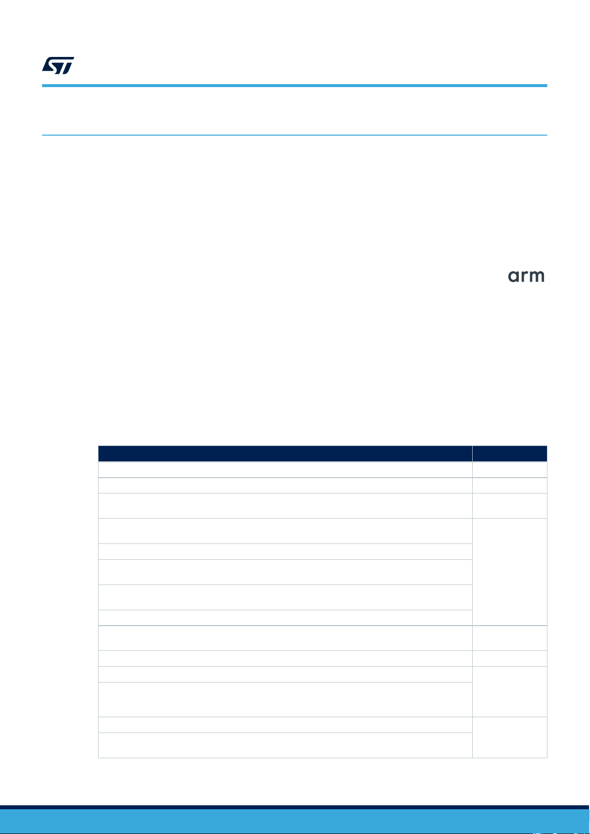
Table 1. Document sections versus IEC 61508-2 Annex D safety requirements
Safety requirement Section number
D2.1 a) a functional specification of the functions capable of being performed 3
D2.1 b) identification of the hardware and/or software configuration of the Compliant item 3.2
D2.1 c) constraints on the use of the Compliant item or assumptions on which analysis of the behavior or
failure rates of the item are based
D2.2 a) the failure modes of the Compliant item due to random hardware failures, that result in a failure
of the function and that are not detected by diagnostics internal to the Compliant item;
D2.2 b) for every failure mode in a), an estimated failure rate;
D2.2 c) the failure modes of the Compliant item due to random hardware failures, that result in a failure
of the function and that are detected by diagnostics internal to the Compliant item;
D2.2 d) the failure modes of the diagnostics, internal to the Compliant item due to random hardware
failures, that result in a failure of the diagnostics to detect failures of the function;
D2.2 e) for every failure mode in c) and d), the estimated failure rate;
D2.2 f) for every failure mode in c) that is detected by diagnostics internal to the Compliant item, the
diagnostic test interval;
D2.2 g) for every failure mode in c) the outputs of the Compliant item initiated by the internal diagnostics; 3.6
D2.2 h) any periodic proof test and/or maintenance requirements;
D2.2 i) for those failure modes, in respect of a specified function, that are capable of being detected by
external diagnostics, sufficient information must be provided to facilitate the development of an external
diagnostics capability.
D2.2 j) the hardware fault tolerance;
D2.2 k) the classification as type A or type B of that part of the Compliant item that provides the function
(see 7.4.4.1.2 and 7.4.4.1.3);
3.2
3.7
3.2.2
3.7
3
UM2714 - Rev 2
page 2/114

1.3 Reference documents
[1] AN5459, FMEDA snapshots for STM32MP1 microprocessor series.
[2] AN5460, Results of FMEA on STM32MP1 Series microprocessor.
UM2714
Reference documents
UM2714 - Rev 2
page 3/114
2 Device development process
STM32 series product development process (see Figure 1), compliant with the IATF 16949 standard, is a set of
interrelated activities dedicated to transform customer specification and market or industry domain requirements
into a semiconductor device and all its associated elements (package, module, sub-system, hardware, software,
and documentation), qualified with ST internal procedures and fitting ST internal or subcontracted manufacturing
technologies.
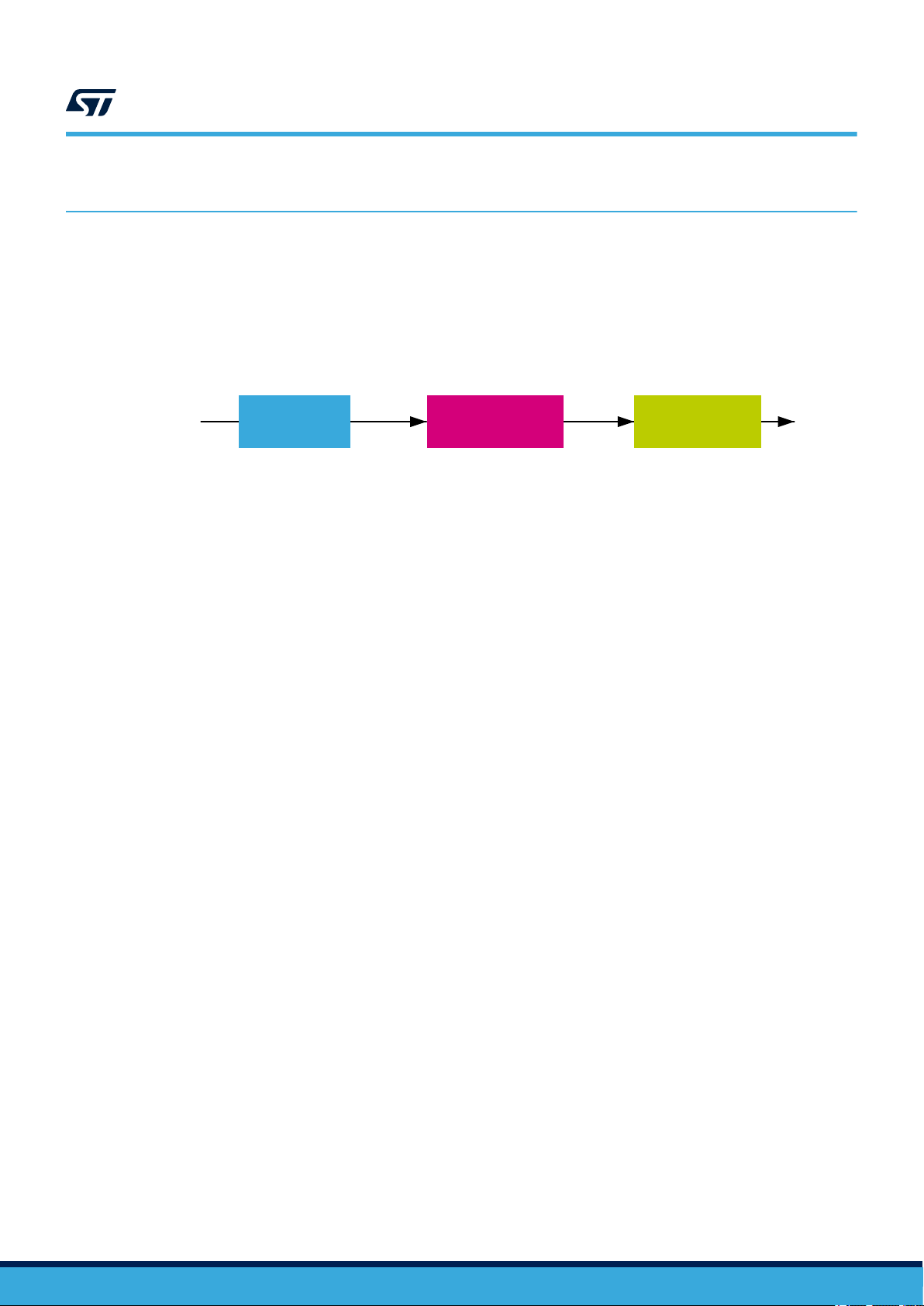
Figure 1. STMicroelectronics product development process
UM2714
Device development process
1 Conception
·Key characteristics and
requirements related to future
uses of the device
·Industry domain(s), specific
customer requirements and
definition of controls and tests
needed for compliance
·Product target specification
and strategy
·Project manager
appointment to drive product
development
·Evaluation of the
technologies, design tools
and IPs to be used
·Design objective
specification and product
validation strategy
·Design for quality
techniques (DFD, DFT, DFR,
DFM, …) definition
·Architecture and positioning
to make sure the software
and hardware system
solutions meet the target
specification
·Product approval strategy
and project plan
2 Design and
validation
·Semiconductor design
development
·Hardware development
·Software development
·Analysis of new product
specification to forecast
reliability performance
·Reliability plan, reliability
design rules, prediction of
failure rates for operating life
test using Arrhenius’s law and
other applicable models
·Use of tools and
methodologies such as
APQP, DFM, DFT, DFMEA
·Detection of potential
reliability issues and solution
to overcome them
·Assessment of Engineering
Samples (ES) to identify the
main potential failure
mechanisms
·Statistical analysis of
electrical parameter drifts for
early warning in case of fast
parametric degradation (such
as retention tests)
·Failure analysis on failed
parts to clarify failure modes
and mechanisms and identify
the root causes
·Physical destructive
analysis on good parts after
reliability tests when required
·Electrostatic discharge
(ESD) and latch-up sensitivity
measurement
3 Qualification
·Successful completion of
the product qualification
plan
·Secure product deliveries
on advanced technologies
using stress methodologies
to detect potential weak
parts
·Successful completion of
electrical characterization
·Global evaluation of new
product performance to
guarantee reliability of
customer manufacturing
process and final application
of use (mission profile)
·Final disposition for
product test, control and
monitoring
UM2714 - Rev 2
page 4/114
3 Reference safety architecture
This section reports details of the STM32MP1 Series safety architecture.
3.1 Safety architecture introduction
Device(s) analyzed in this document can be used as Compliant item(s) within different safety applications.
The aim of this section is to identify such Compliant item(s), that is, to define the context of the analysis with
respect to a reference concept definition. The concept definition contains reference safety requirements, including
design aspects external to the defined Compliant item.
As a consequence of Compliant item approach, the goal is to list the system-related information considered
during the analysis, rather than to provide an exhaustive hazard and risk analysis of the system around the
device.
3.2 Compliant item
This section defines the Compliant item term and provides information on its usage in different safety architecture
schemes.
3.2.1 Definition of Compliant item
According to IEC 61508:1 clause 8.2.12, Compliant item is any item (for example an element) on which a claim is
being made with respect to the clauses of IEC 61508 series. Any mature Compliant item must be described in a
safety manual available to End user.
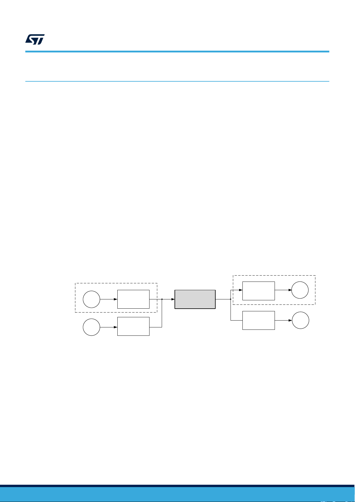
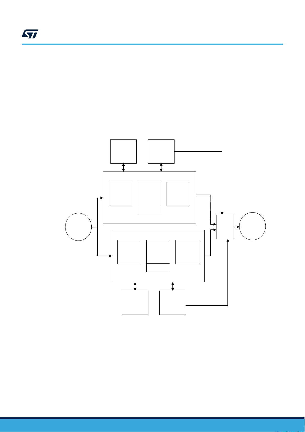
In this document, Compliant item is defined as a system including one or two STM32MP1 devices (see Figure 2).
The communication bus is directly or indirectly connected to sensors and actuators.
UM2714
Reference safety architecture
Figure 2. STM32MP1 as Compliant item
Actuator
Sensor
S
S
In the framework of STM32MP1 safety concept, the Compliant item is assumed to be divided in two partitions:
• Safe Partition, including all STM32MP1 logic considered as safety related and suitable for the
implementation of End User safety functions. This partition includes also the STM32MP1 logic implementing
(in collaboration with application software) the separation (freedom from interference) between itself and the
Non-Safe Partition.
The complete list of STM32MP1 internal modules belonging to Safe Partition is reported in
Section 3.7 Conditions of use. The Arm® Cortex®‑M4 CPU belongs to Safe Partition.
• Non-Safe Partition, including all STM32MP1 logic considered as non-safety related and therefore not
suitable for the implementation of End User safety functions and so out of the safety scope.
The STM32MP1 modules not listed explicitly in Section 3.7 Conditions of use are considered belonging to
Non-Safe Partition. The Arm® A7 CPU belongs to Non-Safe Partition.
Accordingly, the implementation of the End User safety function is restricted to the STM32MP1 logic belonging to
Safe Partition.
Remote
controller
Remote
controller
Processing element
STM32MP1
device(s)
Compliant item
Remote
controller
Remote
controller
A
A
UM2714 - Rev 2
page 5/114

UM2714
Compliant item
Caution:
According to Non-Safe Partition definition, the implementation of safety function(s) based on Arm® A7 CPU is
not allowed.
Interference due to the presence in STM32MP1 device of logic belonging to Non-Safe Partition are managed by
the help of the separation concept, which is described in detail in Section 3.2.5 .
It is worth to note that because of the effective isolation between Safe and Non Safe Partition, the presence of
non-safety related application software running on A7 CPU is allowed. Section 4.2 of this document provides
more information on this specific case.
Other components might be related to the Compliant item, like the external HW components needed to guarantee
either the functionality of the device (external memory, clock quartz and so on) or its safety (for example, the
external watchdog or voltage supervisors). These components are not analyzed in this safety manual.
A defined Compliant item can be classified as element according to IEC61508-4, 3.4.5.
3.2.2 Safety functions performed by Compliant item
In essence, Compliant item architecture encompasses the following processes performing the safety function or a
part of it:
• input processing elements (PEi) reading safety related data from the remote controller connected to the
sensor(s) and transferring them to the following computation elements
• computation processing elements (PEc) performing the algorithm required by the safety function and
transferring the results to the following output elements
• output processing elements (PEo) transferring safety related data to the remote controller connected to the
actuator
• computation processing elements (PEd, see Note) executing hardware and software-based safety functions
devoted to:
1. detect/prevent hardware random failures affecting all considered processing elements (PEi/PEc/PEo/
PEd)
2. prevent/mitigate systematic failures in the software executed on PEc/PEd
3. prevent/detect interferences on the safety related hardware and software caused by the non-safety
related hardware and software
• in 1oo2 architecture, potentially a further voting processing element (PEv)
• processes external to the Compliant item ensuring safety integrity, such as watchdog (WDTe) and voltage
monitors (VMONe)
Note: Because the large part of safety mechanisms included in STM32MP1 are software-based, PEc and PEd
hardware are mainly coincident.
The role of the PEv process is clarified in Section 3.2.4 , while the one of WDTe and VMONe external processes
is clarified in the sections where the conditions of use (CoU) (definition of safety mechanism) are detailed:
• WDTe: refer to External watchdog – CPU_SM_5 and Control flow monitoring in Application software –
CPU_SM_1,
• VMONe: refer to Supply voltage monitoring – VSUP_SM_1 and System-level power supply management VSUP_SM_5.
In summary, the devices support the implementation of End user safety functions consisting of three operations:
• safe acquisition of safety-related data from input peripheral(s)
• safe execution of application software program and safe computation of related data
• safe transfer of results or decisions to output peripheral(s)
Claims on the Compliant item and computation of safety metrics are done with respect to these three basic
operations and to the PEd processes which are integral part of STM32MP1 safety concept.
According to the definition for implemented safety functions, Compliant item (element) can be regarded as type B
(as per IEC61508-2, 7.4.4.1.3 definition). Despite accurate, exhaustive and detailed failure analysis, Device has
to be considered as intrinsically complex. This implies its type B classification.
Two main safety architectures are identified: 1oo1 (using one device) and 1oo2 (using two devices).
3.2.3 Reference safety architectures - 1oo1
1oo1 reference architecture (Figure 3) ensures safety integrity of Compliant item through combining device
internal processes (implemented safety mechanisms) with external processes WDTe and VMONe.
1oo1 reference architecture targets safety integrity level (SIL)SIL2.
UM2714 - Rev 2
page 6/114
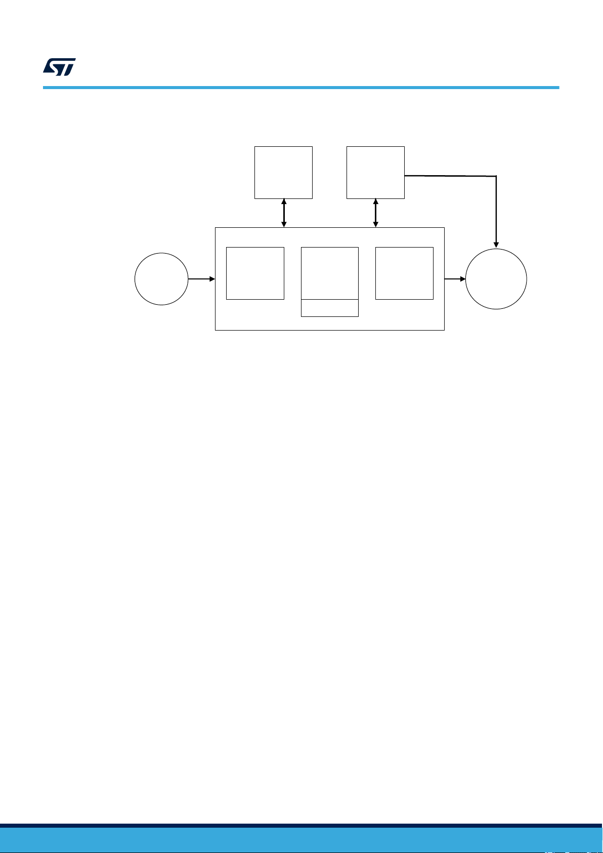
Figure 3. 1oo1 reference architecture
UM2714
Compliant item
Sensors
VMONe
PEc
PEd
WDTe
PEoPEi
Actuators
UM2714 - Rev 2
page 7/114
3.2.4 Reference safety architectures - 1oo2
1oo2 reference architecture (Figure 4) contains two separate channels, either implemented as 1oo1
reference architecture ensuring safety integrity of Compliant item through combining device internal processes
(implemented safety mechanisms) with external processes WDTe and VMONe. The overall safety integrity is then
ensured by the external voter PEv, which allows claiming hardware fault tolerance (HFT) equal to 1. Achievement
of higher safety integrity levels as per IEC61508-2 Table 3 is therefore possible. Appropriate separation between
the two channels (including power supply separation) should be implemented in order to avoid huge impact of
common-cause failures (refer to Section 4.2 Analysis of dependent failures). However, β and βD parameters
computation is required.
1oo2 reference architecture targets SIL3.
Figure 4. 1oo2 reference architecture
UM2714
Compliant item
Sensors
VMONe
PEc
PEd
WDTe
PEc
PEd
PEoPEi
PEv
PEoPEi
Actuators
3.2.5 The separation concept
The Safe Partition and the Non-Safe Partition are isolated by the separation concept, which is composed by two
different aspects, spatial separation and temporal separation.
Spatial separation
Safe and Non-Safe Partitions share the same device (STM32MP1), therefore interferences are possible. The
protection against spatial interferences is built by two successive layers of protection:
• eTZPC protection: the major part of STM32MP1 peripherals and DMA masters belonging to Safe Partition
are "isolable" and so can be allocated to Cortex®-M4 CPU domain accesses exclusively by proper setting of
MCU resource isolation system of the eTZPE controller. Then any access tried by a Non-Safe partition AXI
master like the A7 CPU is detected and stopped by eTZPC hardware module. Note that all the peripherals
which are securable to A7 CPU exclusively are excluded from the Safe Partition and safety concept by
definition.
UM2714 - Rev 2
WDTeVMONe
page 8/114
UM2714
Compliant item
• The local safety concept for each peripheral in Safe Partition, which is composed by several overlapped
safety mechanism defined at application level, is able to detect in efficient way unintended perturbing
accesses coming from Non Safe Partition. All those safety mechanisms are declared as “highly
recommended” in Section 3.7 Table 142. List of safety recommendations, so their presence in the final
system is guaranteed. This protection is quite valuable for the few common resources belonging to Safe
Partitions which cannot be isolated by eTZPC protection, because fully shared with A7 CPU (power and
clock configuration interfaces).
The two layers are overlapped, so the second one acts as second line of defense in case of failures of the main
protection by eTZPC.
The separation concept protects the Safe Partition from unintended accesses regardless their nature on the Non
Safe Partition side, so because of random hardware failures in the hardware or systematic errors in the software.
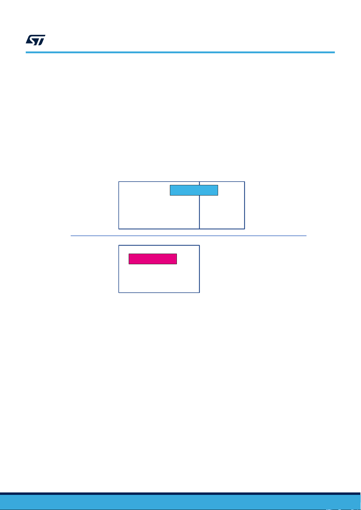
Figure 5 represents the separation concept:
Figure 5. Spatial separation concept
Safe software
Logic implementing
End User safety function(s)
Non-Safe software
Non safety related logic
Logic
implementing
Separation
concept
Safe Partition
Separation
Non-Safe Partition
It is worth to highlight that despite the M4 isolation feature belongs primarily to STM32MP1 security, it is applied
for safety purposes in this specific case.
UM2714 - Rev 2
page 9/114
UM2714
Compliant item
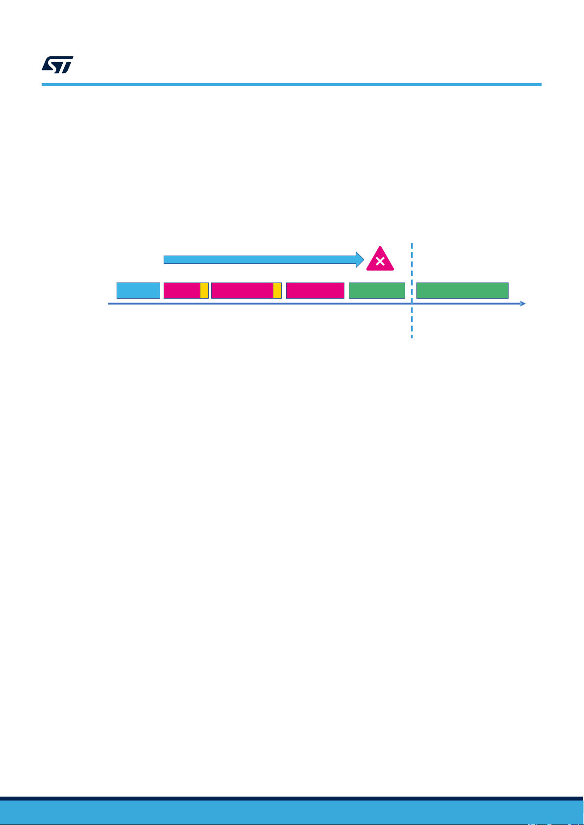
Temporal separation
The temporal separation is required because of the specific boot structure of STM32MP1, where the A7 CPU
is the key player during the boot sequence because it is in charge to load the software image for M4 CPU.
The temporal separation guarantees that any possible interference from non-safety related hardware and/or
software on A7 CPU side during the boot sequence is detected/mitigated by adequate measures implemented
on M4 CPU side (and therefore built over safety related hardware and software). Following picture provides
a graphical representation (red boxes: events on non-safety related resources, green boxes: events on safety
related resources)
Figure 6. Temporal separation concept
Interferences
Power up A7 boot
A7 load image on
M4
A7 releases M4
reset
M4 measures
Temporal
separation
M4 application software starts
Time
The box marked “M4 measures” includes both hardware and software measures. Hardware measures can be
implemented by final system characteristics helping to keep the safe state despite issues occurred during the boot
(for example the presence of an intelligent external watchdog), while software measures can be implemented
by additional checks executed on M4 CPU just after its startup and before the execution of the end user safety
application software. These measures are detailed in Section 3.7 in form of CoU.
It is worth to note that the authentication features implemented in first stage boot loader (FSBL) and that can be
activated in second stage boot loader (U-Boot), despite mainly conceived for security reasons, can be considered
as part of the temporal separation implementation because they protect the integrity of the software images
loaded during the boot. That protection. represented Figure 6 by the yellow boxes, can be considered valid as per
the outcomes of CoU_17 application.
UM2714 - Rev 2
page 10/114
Safety analysis assumptions
3.3 Safety analysis assumptions
This section collects all assumptions made during the safety analysis of the devices.
3.3.1 Safety requirement assumptions
The concept specification, the hazard and risk analysis, the overall safety requirement specification and the
consequent allocation determine the requirements for Compliant item as further listed. ASR stands for assumed
safety requirements.
Caution: It is the End user’s responsibility to check the compliance of the final application with these assumptions.
Furthermore, beside the recommendation included in this Safety Manual, it is also End user’s responsibility to
guarantee the compliance of the final application with the requirements of the IEC61508.
ASR1: Compliant item can be used to implement four kinds of safety function modes of operation according to
part 4,3.5.16:
• a continuous mode (CM) or high-demand (HD) SIL3 safety function (CM3), or
• a low-demand (LD) SIL3 safety function (LD3), or
• a CM or HD SIL2 safety function (CM2), or
• a LD SIL2 safety function (LD2).
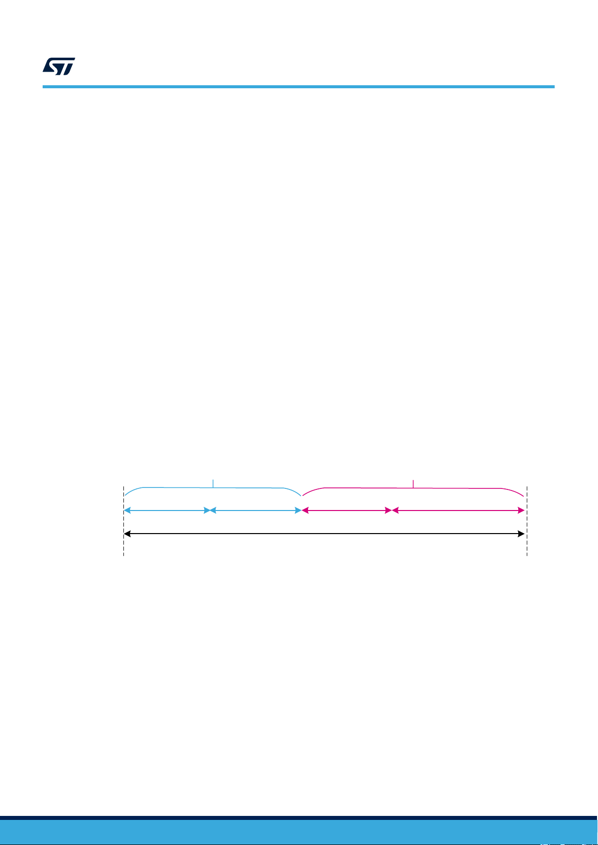
ASR2: Compliant item is used to implement safety function(s) allowing a specific worst-case time budget (see
note below) for the STM32 MPU to detect and react to a failure. That time corresponds to the portion of the
process safety time (PST) allocated to the device (STM32xx Series duty in Figure 7) in error reaction chain at
system level.
Note: The computation for time budget mainly depends on the execution speed for periodic tests implemented
by software. Such duration might depends on the actual amount of hardware resources (RAM memory and
peripherals) actually declared as safety-related. Further constraints and requirements from IEC61508-2, 7.4.5.3
must be considered.
UM2714
Figure 7. Allocation and target for STM32 PST
STM32xx Series duty End user duty
MPU detection FW reaction SW reaction Actuator reaction
System-level PST
….
ASR3: Compliant item is used to implement safety function(s) that can be continuously powered on for a period
over eight hours. It is assumed to not require any proof test, and the lifetime of the product is considered to be no
less than 10 years.
ASR4.1: It is assumed that End User safety functions are implemented only on Device logic belonging to the Safe
Partition.
ASR4.2: It is assumed that logic and resources belonging to Safe Partition are not used for the implementation of
non-safety related functions, coexisting with safety functions.
ASR4.3: It is assumed that the software functions running on A7 CPU have been developed according some
specific quality standards.
Note: This Assumption is not placed to require a formal compliance of A7 software development flow to IEC61508
model, but to guarantee a minimum quality of the software running on the Non-Safe partition. Related CoU_17
provides more specific insights.
ASR4.4: It is assumed that only one safety function is performed or if many, all functions are classified with the
same SIL and therefore they are not distinguishable in terms of their safety requirements.
ASR4.5: In case of multiple safety function implementations, it is assumed that End user is responsible to duly
ensure their mutual independence.
‑
3
UM2714 - Rev 2
page 11/114

UM2714
Electrical specifications and environment limits
ASR5: It is assumed that the implemented safety function(s) does (do) not depend on transition of the overall
STM32MP1 or Arm® Cortex®-M4 CPU to and from a low-power or suspended state.
ASR6.1: The local safe state of Compliant item is the one in which either:
• SS1: the application software
software
(1)
itself is possible.
• SS2: the application software
not able to execute a reaction.
Note: End user must consider that random hardware failures affecting the Device can compromise its operations (for
example failure modes affecting the program counter prevent the correct execution of software).
The following table provides details on the SS1 and SS2 safe states.
(1)
is informed by the presence of a fault and a reaction by the application
(1)
cannot be informed by the presence of a fault or the application software
Table 2. SS1 and SS2 safe state details
(1)
is
Safe
state
The application software
informed by the presence of
SS1
a fault and a reaction by
the application software itself is
possible.
The application software
be informed by the presence of a
SS2
fault or the application software is
1.
2. Safe state achievement intended here is compliant to Note on IEC 61508-2, 7.4.8.1
not able to execute a reaction.
Referred to application software executed on Arm® Cortex®-M4 CPU.
Condition
(1)
is
(1)
cannot
Compliant item
action
Fault reporting
to application
software
Reset signal
issued by WDTe
(1)
System transition to safe
state – 1oo1 architecture
(2)
(1)
drives
Application software
the overall system in its safe
state
WDTe drives the overall
system in its safe state
(“safe shut-down”)
System transition to safe
state – 1oo2 architecture
Application software
of the two channels drives
the overall system in its safe
state
PEv drives the overall system
in its safe state
ASR6.2: It is assumed that the safe state defined at system level by End user is compatible with the assumed
local safe state (SS1, SS2) for Compliant item.
ASR7: Compliant item is assumed to be analyzed according to routes 1H and 1S of IEC 61508-2.
Note: Refer to Section 3.5 Systematic safety integrity and Section 3.6 Hardware and software diagnostics.
ASR8: Compliant item is assumed to be regarded as type B, as per IEC 61508:2, 7.4.4.1.2.
ASR9: It is assumed that data exchanges between the Safe Partition and the Non-Safe Partition are implemented
by using statically allocated locations in SYSRAM bank and restricted to non-safety related data.
ASR10.1: STM32MP1 package is considered full safety related, in the framework of Device failure rate
computations.
ASR10.2: is End User responsibility to prove the freedom from interferences between safety related and nonsafety related physical pins (e.g. by running a pin-level FMEDA).
ASR11: it is assumed that glitches in GPIO output values with a duration lower than the adopted PST are not able
to cause violations of the implemented safety function(s)
Note: This assumption can be fulfilled in two ways, either:
• Final application robustness against GPIO glitches, as required by the assumption text
or
• The execution frequency of the prescribed method GPIO_SM_2 and GPIO_SM_0 is higher than 1/Tm
(refer to related “Recommendations and known limitations“ fields for details)
ASR12: it is assumed that STM32MP1 is not used to build fail-operational solutions based exclusively on the
resources of a unique STM32MP1 device itself.
(1)
in one
3.4
UM2714 - Rev 2
Electrical specifications and environment limits
To ensure safety integrity, the user must operate the Device(s) within its (their) specified:
• absolute maximum rating
page 12/114

• capacity
• operating conditions
For electrical specifications and environmental limits of Device(s), refer to its (their) technical documentation such
as datasheet(s) and reference manual(s) available on www.st.com.
3.5 Systematic safety integrity
According to the requirements of IEC 61508-2, 7.4.2.2, the Route 1S is considered in the analysis of Device(s).
As clearly authorized by IEC61508-2, 7.4.6.1, STM32 MPU products can be considered as standard, massproduced electronic integrated devices, for which stringent development procedures, rigorous testing and
extensive experience of use minimize the likelihood of design faults. However, ST internally assesses the
compliance of the Device development flow, through techniques and measures suggested in the IEC 61508-2
Annex F. A safety case database (see Section 5 List of evidences) keeps evidences of the current compliance
level to the norm.
3.6 Hardware and software diagnostics
This section lists all the safety mechanisms (hardware, software and application-level) considered in the
device safety analysis. It is expected that users are familiar with the architecture of the device, and that this
document is used in conjunction with the related device datasheet, user manual and reference information. To
avoid inconsistency and redundancy, this document does not report device functional details. In the following
descriptions, the words safety mechanism, method, and requirement are used as synonyms.
As the document provides information relative to the superset of peripherals available on the devices it covers
(not all devices have all peripherals), users are supposed to disregard any recommendations not applicable to
their Device part number of interest.
Information provided for a function or peripheral applies to all instances of such function or peripheral on Device.
Refer to its reference manual or/and datasheet for related information.
The implementation guidelines reported in the following section are for reference only. The safety verification
executed by ST during the device safety analysis and related diagnostic coverage figures reported in this manual
(or related documents) are based on such guidelines. For clarity, safety mechanisms are grouped by Device
function.
Information is organized in form of tables, one per safety mechanism, with the following fields:
UM2714
Systematic safety integrity
SM CODE Unique safety mechanism code/identifier used also in FMEA document. Identifiers use the scheme
Description Short mnemonic description
Ownership ST : means that method is available on silicon.
Detailed
implementation
Error reporting Describes how the fault detection is reported to application software.
Fault detection time Time that the safety mechanism needs to detect the hardware failure.
Addressed fault
model
Dependency on
Device configuration
Initialization Specific operation to be executed to activate the contribution of the safety mechanism
mmm_SM_x where mmm is a 3- or 4-letter module (function, peripheral) short name, and x is a
number. It is possible that the numbering is not sequential (although usually incremental) and/or that
the module short name is different from that used in other documents.
End user: method must be implemented by End user through Application software modification,
hardware solutions, or both.
Detailed implementation sometimes including notes about the safety concept behind the introduction
of the safety mechanism.
Reports fault model(s) addressed by the diagnostic (permanent, transient, or both), and other
information:
• If ranked for Fault avoidance: method contributes to lower the probability of occurrence of a
failure
• If ranked for Systematic: method is conceived to mitigate systematic errors (bugs) in
application software design
Reports if safety mechanism implementation or characteristics change among different Device part
numbers.
UM2714 - Rev 2
page 13/114

3.6.1
UM2714
Hardware and software diagnostics
Periodicity Continuous : safety mechanism is active in continuous mode.
Periodic: safety mechanism is executed periodically
On-demand: safety mechanism is activated in correspondence to a specified event (for instance,
reception of a data message).
Startup: safety mechanism is supposed to be executed only at power-up or during off-line
maintenance periods.
Test for the
diagnostic
Multiple-fault
protection
Recommendations
and known limitations
Reports specific procedure (if any and recommended) to allow on-line tests of safety mechanism
efficiency.
Reports the safety mechanism(s) associated in order to correctly manage a multiple-fault scenario
(refer to Section 4.1.3 Notes on multiple-fault scenario).
Additional recommendations or limitations (if any) not reported in other fields.
1. In CM systems, safety mechanism can be accounted for diagnostic coverage contribution only if it is executed at least once
per PST. For LD and HD systems, constraints from IEC61508-2, 7.4.5.3 must be applied.
Arm® Cortex®-M4 CPU
Table 3. CPU_SM_0
(1)
.
SM CODE CPU_SM_0
Description
Ownership End user or ST
Detailed implementation
Error reporting Depends on implementation
Fault detection time Depends on implementation
Addressed fault model Permanent
Dependency on Device configuration None
Initialization None
Periodicity Periodic
Test for the diagnostic
Multiple-fault protection CPU_SM_5: external watchdog
Recommendations and known limitations
Periodical core self-test software for Arm® Cortex®-M4 CPU
The software test is built around well-known techniques already addressed by IEC 61508:7,
A.3.2 (Self-test by software: walking bit one-channel). To reach the required values of
coverage, the self-test software is specified by means of a detailed analysis of all the CPU
failure modes and related failure modes distribution
Self-diagnostic capabilities can be embedded in the software, according the test
implementation design strategy chosen. The adoption of checksum protection on results
variables and defensive programming are recommended.
This method is the main asset in STM32MP1 Series safety concept. CPU integrity is a key
factor because the defined diagnostics for MPU peripherals are to major part software-based.
Startup execution of this safety mechanism is recommended for multiple fault mitigations refer to Section 4.1.3 Notes on multiple-fault scenario for details.
UM2714 - Rev 2
page 14/114

SM CODE CPU_SM_1
Description Control flow monitoring in Application software
Ownership End user
Detailed implementation
Error reporting Depends on implementation
Fault detection time Depends on implementation. Higher value is fixed by watchdog timeout interval.
Addressed fault model Permanent and transient
Dependency on Device configuration None
Initialization Depends on implementation
Periodicity Continuous
Test for the diagnostic NA
Multiple-fault protection CPU_SM_0: periodical core self-test software
Recommendations and known limitations -
UM2714
Hardware and software diagnostics
Table 4. CPU_SM_1
A significant part of the failure distribution of CPU core for permanent faults is related to
failure modes directly related to program counter loss of control or hang-up. Due to their
intrinsic nature, such failure modes are not addressed by a standard software test method
like SM_CPU_0. Therefore it is necessary to implement a run-time control of the Application
software flow, in order to monitor and detect deviation from the expected behavior due to such
faults. Linking this mechanism to watchdog firing assures that severe loss of control (or, in the
worst case, a program counter hang-up) is detected.
The guidelines for the implementation of the method are the following:
• Different internal states of the Application software are well documented and described
(the use of a dynamic state transition graph is encouraged).
• Monitoring of the correctness of each transition between different states of the
Application software is implemented.
• Transition through all expected states during the normal Application software program
loop is checked.
• A function in charge of triggering the system watchdog is implemented in order to
constrain the triggering (preventing the issue of CPU reset by watchdog) also to the
correct execution of the above-described method for program flow monitoring. The use
of window feature available on internal window watchdog (WWDG) is recommended.
• The use of the independent watchdog (IWDG), or an external one, helps to implement a
more robust control flow mechanism fed by a different clock source.
In any case, safety metrics do not depend on the kind of watchdog in use (the adoption
of independent or external watchdog contributes to the mitigation of dependent failures, see
Section 4.2.2 Clock)
UM2714 - Rev 2
page 15/114

SM CODE CPU_SM_2
Description Double computation in Application software
Ownership End user
Detailed implementation
Error reporting Depends on implementation
Fault detection time Depends on implementation
Addressed fault model Transient
Dependency on Device configuration None
Initialization Depends on implementation
Periodicity Continuous
Test for the diagnostic Not needed
Multiple-fault protection CPU_SM_0: periodical core self-test software
Recommendations and known limitations
UM2714
Hardware and software diagnostics
Table 5. CPU_SM_2
A timing redundancy for safety-related computation is considered to detect transient faults
affecting the Arm® Cortex®-M4 CPU subparts devoted to mathematical computations and data
access.
The guidelines for the implementation of the method are the following:
• The requirement needs be applied only to safety-relevant computation, which in case of
wrong result could interfere with the system safety functions. Such computation must be
therefore carefully identified in the original Application software source code
• Both mathematical operation and comparison are intended as computation.
• The redundant computation for mathematical computation is implemented by using
copies of the original data for second computation, and by using an equivalent formula if
possible
End user is responsible to carefully avoid that the intervention of optimization features of the
used compiler removes timing redundancies introduced according to this condition of use.
Table 6. CPU_SM_3
SM CODE CPU_SM_3
Description
Ownership ST
Detailed implementation
Error reporting High-priority interrupt event
Fault detection time Depends on implementation. Refer to functional documentation.
Addressed fault model Permanent and transient
Dependency on Device configuration None
Initialization None
Periodicity Continuous
Test for the diagnostic
Multiple-fault protection CPU_SM_0: periodical core self-test software
Recommendations and known limitations Enabling related interrupt generation on the detection of errors is highly recommended.
Arm® Cortex®-M4 HardFault exceptions
HardFault exception raise is an intrinsic safety mechanism implemented in Arm® Cortex®-M4
core, mainly dedicated to intercept systematic faults due to software limitations or error in
software design (causing for example execution of undefined operations, unaligned address
access). This safety mechanism is also able to detect hardware random faults inside the CPU
bringing to such described abnormal operations.
It is possible to write a test procedure to verify the generation of the HardFault exception;
anyway, given the expected minor contribution in terms of hardware random-failure detection,
such implementation is not recommended.
UM2714 - Rev 2
page 16/114

SM CODE CPU_SM_4
Description Stack hardening for Application software
Ownership End user
Detailed implementation
Error reporting Depends on implementation
Fault detection time Depends on implementation
Addressed fault model Permanent and transient
Dependency on Device configuration None
Initialization Depends on implementation
Periodicity On demand
Test for the diagnostic Not needed
Multiple-fault protection CPU_SM_0: periodical core self-test software
Recommendations and known limitations
UM2714
Hardware and software diagnostics
Table 7. CPU_SM_4
The stack hardening method is required to address faults (mainly transient) affecting CPU
register bank. This method is based on source code modification, introducing information
redundancy in register-passed information to called functions.
The guidelines for the implementation of the method are the following:
• To pass also a redundant copy of the passed parameters values (possibly inverted) and
to execute a coherence check in the function.
• To pass also a redundant copy of the passed pointers and to execute a coherence
check in the function.
• For parameters that are not protected by redundancy, to implement defensive
programming techniques (plausibility check of passed values). For example enumerated
fields are to be checked for consistency.
This method partially overlaps with defensive programming techniques required by IEC61508
for software development. Therefore in presence of Application software qualified for safety
integrity greater or equal to SC2, optimizations are possible.
Table 8. CPU_SM_5
SM CODE CPU_SM_5
Description External watchdog
Ownership End user
Using an external watchdog linked to control flow monitoring method (refer to CPU_SM_1)
addresses failure mode of program counter or control structures of CPU.
External watchdog can be designed to be able to generate the combination of signals needed
Detailed implementation
Error reporting Depends on implementation
Fault detection time Depends on implementation (watchdog timeout interval)
Addressed fault model Permanent and transient
Dependency on Device configuration None
Initialization Depends on implementation
Periodicity Continuous
Test for the diagnostic To be defined at system level (outside the scope of Compliant item analysis)
Multiple-fault protection CPU_SM_1: control flow monitoring in Application software
on the final system to achieve the safe state. It is recommended to carefully check the
assumed requirements about system safe state reported in Section 3.3.1 Safety requirement
assumptions.
It also contributes to reduce potential common cause failures, because the external watchdog
is clocked and supplied independently of Device.
UM2714 - Rev 2
page 17/114

SM CODE CPU_SM_5
Recommendations and known limitations
SM CODE CPU_SM_6
Description MCU window watchdog
Ownership ST
Detailed implementation
Error reporting Reset signal generation
Fault detection time Depends on implementation (watchdog timeout interval)
Addressed fault model Permanent
Dependency on Device configuration None
Initialization
Periodicity Continuous
Test for the diagnostic WDG_SM_1: Software test for watchdog at startup
Multiple-fault protection
Recommendations and known limitations
UM2714
Hardware and software diagnostics
CPU_SM_6: MCU window watchdog
In case of usage of windowed watchdog, End user must consider possible tolerance in
Application software execution, to avoid false error reports (affecting system availability).
Table 9. CPU_SM_6
Using the WWDG1 watchdog linked to control flow monitoring method (refer to CPU_SM_1)
addresses failure mode of program counter or control structures of CPU.
WWDG1 activation. It is recommended to use hardware watchdog in Option byte settings
(WWDG1 is automatically enabled after reset)
CPU_SM_1: control flow monitoring in Application software
WDG_SM_0: periodical read-back of configuration registers
The WWDG1 intervention is able to achieve a potentially “incomplete” local safe state
because it can only guarantee that CPU is reset. No guarantee that Application software
can be still executed to generate combinations of output signals that might be needed by the
external system to achieve the final safe state.
SM CODE CPU_SM_7
Description Memory protection unit (MPU)
Ownership ST
Detailed implementation
Error reporting Exception raise (MemManage)
Fault detection time Refer to functional documentation
Addressed fault model
Dependency on Device configuration None
Initialization MPU registers must be programmed at start-up
Periodicity On line
Test for the diagnostic Not needed
Multiple-fault protection MPU_SM_0: Periodical read-back of configuration registers
Recommendations and known limitations
Table 10. CPU_SM_7
The CPU memory protection unit is able to detect illegal access to protected memory areas,
according to criteria set by End user.
Systematic (software errors)
Permanent and transient (only program counter and memory access failures)
The use of memory partitioning and protection by MPU functions is highly recommended
when multiple safety functions are implemented in Application software. The MPU can be
indeed used to
• enforce privilege rules
UM2714 - Rev 2
page 18/114

SM CODE CPU_SM_7
• separate processes
• enforce access rules
Hardware random-failure detection capability for MPU is restricted to well-selected failure
modes, mainly affecting program counter and memory access CPU functions. The associated
diagnostic coverage is therefore not expected to be relevant for the safety concept of Device.
Enabling related interrupt generation on the detection of errors is highly recommended.
Table 11. MPU_SM_0
SM CODE MPU_SM_0
Description Periodical read-back of MPU configuration registers
Ownership End user
This method must be applied to MPU configuration registers (also unused by the End
Detailed implementation
Error reporting Refer to NVIC_SM_0
Fault detection time Refer to NVIC_SM_0
Addressed fault model Refer to NVIC_SM_0
Dependency on Device configuration Refer to NVIC_SM_0
Initialization Refer to NVIC_SM_0
Periodicity Refer to NVIC_SM_0
Test for the diagnostic Refer to NVIC_SM_0
Multiple-fault protection Refer to NVIC_SM_0
Recommendations and known limitations Refer to NVIC_SM_0
userApplication software).
Detailed information on the implementation of this method can be found in
Section 3.6.4 EXTI controller.
UM2714
Hardware and software diagnostics
Table 12. MPU_SM_1
SM CODE MPU_SM_1
Description MPU software test.
Ownership End User.
This method tests MPU capability to detect and report memory accesses violating the policy
enforcement implemented by the MPU itself.
Detailed implementation
Error reporting Depends on implementation.
Fault detection Time Depends on implementation.
Addressed Fault Model Permanent.
Dependency on device configuration None.
Initialization Depends on implementation.
Periodicity On demand.
Test for the diagnostic Not needed.
Multiple faults protection CPU_SM_0: Periodical core self test software
The implementation is based on intentionally performing memory accesses (in writing and read) to
memory areas outside of the allowed by the MPU regions programming, and to collect and verify
related generated error exceptions.
Test can be executed with the final MPU region programming or with a dedicated one.
UM2714 - Rev 2
page 19/114

SM CODE MPU_SM_1
Recommendations and known
limitations
UM2714
Hardware and software diagnostics
Startup execution of this safety mechanism is recommended for multiple fault mitigations - refer to
Section 4.1.3 Notes on multiple-fault scenario for details.
UM2714 - Rev 2
page 20/114

3.6.2 Embedded SRAM1/2/3/4
Table 13. RAM_SM_0
SM CODE RAM_SM_0
Description Periodical software test for static random access memory (SRAM or RAM)
Ownership End user or ST
To enhance the coverage on SRAM data cells and to ensure adequate coverage for
Detailed implementation
Error reporting Depends on implementation
Fault detection time Depends on implementation
Addressed fault model Permanent
Dependency on Device configuration RAM size can change according to the part number
Initialization Depends on implementation
Periodicity Periodic
Test for the diagnostic
Multiple-fault protection CPU_SM_0: periodical core self-test software
Recommendations and known limitations
permanent faults affecting the address decoder it is required to execute a periodical software
test on the system RAM memory. The selection of the algorithm must ensure the target SFF
coverage for both the RAM cells and the address decoder. Evidences of the effectiveness of
the coverage of the selected method must be also collected
Self-diagnostic capabilities can be embedded in the software, according the test
implementation design strategy chosen
Usage of a March test C- is recommended.
Because the nature of this test can be destructive, RAM contents restore must be
implemented. Possible interferences with interrupt-serving routines fired during test execution
must be also considered (such routines can access to RAM invalid contents).
Unused RAM sections can be excluded by the testing, under end user responsibility on actual
RAM usage by final application software
Startup execution of this safety mechanism is recommended for multiple fault mitigations refer to Section 4.1.3 Notes on multiple-fault scenario for details.
RAM sections hosting application software or diagnostic libraries can be excluded by
the testing with this method, if correctly protected by the dedicated safety mechanism
CPU_SM_5. Indeed the diagnostic coverage granted by CPU_SM_5 permits to avoid the
overlap of the two methods on the same RAM area.
UM2714
Hardware and software diagnostics
UM2714 - Rev 2
page 21/114

Table 14. RAM_SM_2
SM CODE RAM_SM_2
Description Stack hardening for application software
Ownership End user
The stack hardening method is used to enhance the application software robustness to SRAM
faults that affect the address decoder. The method is based on source code modification,
introducing information redundancy in the stack-passed information to the called functions.
Detailed implementation
Error reporting Refer to CPU_SM_4
Fault detection time Refer to CPU_SM_4
Addressed fault model Refer to CPU_SM_4
Dependency on Device configuration Refer to CPU_SM_4
Initialization Refer to CPU_SM_4
Periodicity Refer to CPU_SM_4
Test for the diagnostic Refer to CPU_SM_4
Multiple-fault protection Refer to CPU_SM_4
Recommendations and known limitations Refer to CPU_SM_4
Method contribution is relevant in case the combination between the final application software
structure and the compiler settings requires a significant use of the stack for passing function
parameters.
Implementation is the same as method CPU_SM_4
UM2714
Hardware and software diagnostics
Table 15. RAM_SM_3
SM CODE RAM_SM_3
Description Information redundancy for safety-related variables in application software
Ownership End user
To address transient faults affecting SRAM controller, it is required to implement information
redundancy on the safety-related system variables stored in the RAM.
The guidelines for the implementation of this method are the following:
• The system variables that are safety-related (in the sense that a wrong value due to
a failure in reading on the RAM affects the safety functions) are well-identified and
documented.
Detailed implementation
Error reporting Depends on implementation
Fault detection time Depends on implementation
Addressed fault model Permanent and transient
Dependency on Device configuration None
Initialization Depends on implementation
Periodicity On demand
Test for the diagnostic Not needed
Multiple-fault protection CPU_SM_0: periodical core self-test software
• The arithmetic computation or decision based on such variables are executed twice and
the two final results are compared.
• Safety-related variables are stored and updated in two redundant locations, and
comparison is checked before consuming data.
• Enumerated fields must use non-trivial values, checked for coherence at least one time
per PST
• Data vectors stored in SRAM must be protected by a encoding checksum (such as
CRC)
UM2714 - Rev 2
page 22/114

Hardware and software diagnostics
SM CODE RAM_SM_3
Implementation of this safety method shows a partial overlap with an already foreseen method
Recommendations and known limitations
for Arm®Cortex®-M4 (CPU_SM_1); optimizations in implementing both methods are therefore
possible
Table 16. RAM_SM_4
SM CODE RAM_SM_4
Description Control flow monitoring in application software
Ownership End user
Because end user application software is executed from SRAM, permanent and transient
faults affecting the memory (cells and address decoder) can interfere with the program
Detailed implementation
Error reporting Depends on implementation
Fault detection time Depends on implementation. Higher value is fixed by watchdog timeout interval.
Addressed fault model Permanent and transient
Dependency on Device configuration None
Initialization Depends on implementation
Periodicity Continuous
Test for the diagnostic NA
Multiple-fault protection CPU_SM_0: periodical core self-test software
Recommendations and known limitations CPU_SM_1 correct implementation supersedes this requirement
execution.
To address such failures it is needed to implement this method.
For more details on the implementation, refer to description CPU_SM_1
UM2714
SM CODE RAM_SM_5
Description Periodical integrity test for application software in RAM
Ownership End user
Because application software and diagnostic libraries are executed in RAM, it is needed
to protect the integrity of the code itself against soft-error corruptions and related code
mutations. This method must check the integrity of the stored code by checksum computation
techniques, on a periodic basis (at least once per PST), or another timing constraint; refer to
(1)
Detailed implementation
Error reporting Depends on implementation
Fault detection time Depends on implementation
Addressed fault model Permanent and transient
Dependency on Device configuration None
Initialization Depends on implementation
Periodicity Periodic
in Section 3.6 Hardware and software diagnostics. RAM memory cell contents are then
checked versus the expected values, using signature-based techniques. According to IEC
61508:2 Table A.5, the effective diagnostic coverage of such techniques depends on the width
of the signature in relation to the block length of the information to be protected - therefore
the signature computation method must be carefully selected. Note that the simple signature
method (IEC 61508:7 - A.4.2 Modified checksum) is inadequate as it only achieves a low
value of coverage. The use of internal hardware CRC module is therefore recommended.
Table 17. RAM_SM_5
UM2714 - Rev 2
page 23/114

SM CODE RAM_SM_5
Test for the diagnostic
Multiple-fault protection
Recommendations and known limitations
SM CODE RAM_SM_9
Description SRAM static data encapsulation
Ownership End user
Detailed implementation
Error reporting Depends on implementation
Fault detection time Depends on implementation
Addressed fault model Permanent and transient
Dependency on Device configuration None
Initialization Depends on implementation
Periodicity On demand
Test for the diagnostic Not needed
Multiple-fault protection CPU_SM_0: periodical core self test software
Recommendations and known limitations None
Self-diagnostic capabilities can be embedded in the software, according the test
implementation design strategy chosen.
CPU_SM_0: periodical core self test software
CPU_SM_1: control flow monitoring in application software
Refer to RAM_SM_0 description for information about the management of the overlap on
RAM between that method and this one.
If static data are stored in SRAM, encapsulation by a checksum field with encoding capability
(such as CRC) must be implemented.
Checksum validity is checked by application software before static data consuming.
UM2714
Hardware and software diagnostics
Table 18. RAM_SM_9
3.6.3 System bus architecture/peripherals interconnect matrix
Table 19. BUS_SM_0
SM CODE BUS_SM_0
Description Periodical software test for interconnections
Ownership End user
The intra-chip connection resources (main AHB interconnection matrix, AHB or APB bridges)
needs to be periodically tested for permanent faults detection. Note that STM32MP1
Series devices have no hardware safety mechanism to protect these structures. The test
Detailed implementation
Error reporting Depends on implementation
Fault detection time Depends on implementation
Addressed fault model Permanent
Dependency on Device configuration None
Initialization Depends on implementation
Periodicity Periodic
Test for the diagnostic Not needed
executes a connectivity test of these shared resources, including the testing of the arbitration
mechanisms between peripherals.
According to IEC 61508:2 Table A.8, A.7.4 the method is considered able to achieve high
levels of coverage
UM2714 - Rev 2
page 24/114

SM CODE BUS_SM_0
Multiple-fault protection CPU_SM_0: periodical core self-test software
Recommendations and known limitations
SM CODE BUS_SM_1
Description Information redundancy in intra-chip data exchanges
Ownership End user
Detailed implementation
Error reporting Depends on implementation
Fault detection time Depends on implementation
Addressed fault model Permanent and Transient
Dependency on Device configuration None
Initialization Depends on implementation
Periodicity On demand
Test for the diagnostic Not needed
Multiple-fault protection CPU_SM_0: periodical core self-test software
Recommendations and known limitations
UM2714
Hardware and software diagnostics
Implementation can be considered in large part as overlapping with the widely used Periodical
read-back of configuration registers required for several peripherals
Table 20. BUS_SM_1
This method requires to add some kind of redundancy (for example a CRC checksum at
packet level) to each data message exchanged inside Device.
Message integrity is verified using the checksum by the application software, before
consuming data.
Implementation can be in large part overlapping with other safety mechanisms requiring
information redundancy on data messages for communication peripherals. Optimizations are
therefore possible.
Table 21. LOCK_SM_0
SM CODE LOCK_SM_0
Description Lock mechanism for configuration options
Ownership ST
The STM32MP1 Series devices feature spread protection to prevent unintended configuration
Detailed implementation
Error reporting Not generated (when locked, register overwrites are just ignored)
Fault detection time NA
Addressed fault model None (Systematic only)
Dependency on Device configuration None
Initialization Depends on implementation
Periodicity Continuous
Test for the diagnostic Not needed
Multiple-fault protection Not needed
Recommendations and known limitations No DC associated because this test addresses software systematic faults
changes for some peripherals and system registers (for example PVD lock enable bit, timers);
the spread protection detects systematic faults in software application. The use of this method
is encouraged to enhance the end application robustness to systematic faults.
UM2714 - Rev 2
page 25/114

UM2714
Hardware and software diagnostics
3.6.4 EXTI controller
Table 22. NVIC_SM_0
SM CODE NVIC_SM_0
Description Periodical read-back of configuration registers
Ownership End user
This test is implemented by executing a periodical check of the configuration registers for
a system peripheral against its expected value. Expected values are previously stored in
RAM and adequately updated after each configuration change. The method mainly addresses
transient faults affecting the configuration registers, by detecting bit flips in the registers
contents. It addresses also permanent faults on registers because it is executed at least
one time within PST (or another timing constraint; refer to
software diagnostics) after a peripheral update.
Method must be implemented to any configuration register whose contents are able to
interfere with NVIC or EXTI behavior in case of incorrect settings. Check includes NVIC vector
table.
Detailed implementation
Error reporting Depends on implementation
Fault detection time Depends on implementation
Addressed fault model Permanent/transient
Dependency on Device configuration None
Initialization Values of configuration registers must be read after the boot before executing the first check
Periodicity Periodic
Test for the diagnostic Not required
Multiple-fault protection CPU_SM_0: Periodic core self-test software
Recommendations and known limitations
According to the state-of-the-art automotive safety standard ISO26262, this method can
achieve high levels of diagnostic coverage (DC) (refer to ISO26262:5, Table D.4)
An alternative valid implementation requiring less space in SRAM can be realized on the basis
of signature concept:
• Peripheral registers to be checked are read in a row, computing a CRC checksum (use
of hardware CRC is encouraged)
• Obtained signature is compared with the golden value (computed in the same way after
each register update, and stored in SRAM)
• Coherence between signatures is checked by the application software – signature
mismatch is considered as failure detection
This method addresses only failures affecting configuration registers, and not peripheral core
logic or external interface.
Attention must be paid to registers containing mixed combination of configuration and status
bits. Mask must be used before saving register contents affecting signature, and related
checks, to avoid false positive detections.
(1)
in Section 3.6 Hardware and
UM2714 - Rev 2
page 26/114

Table 23. NVIC_SM_1
SM CODE NVIC_SM_1
Description Expected and unexpected interrupt check
Ownership End user
According to IEC 61508:2 Table A.1 recommendations, a diagnostic measure for continuous,
absence or cross-over of interrupt must be implemented. The method of expected and
unexpected interrupt check is implemented at application software level.
The guidelines for the implementation of the method are the following:
• The interrupts implemented on the MPU are well documented, also reporting, when
possible, the expected frequency of each request (for example, the interrupts related to
ADC conversion completion that come on a regular basis).
• Individual counters are maintained for each interrupt request served, in order to detect in
a given time frame the cases of a) no interrupt at all b) too many interrupt requests
(“babbling idiot” interrupt source). The control of the time frame duration must be
regulated according to the individual interrupt expected frequency.
Detailed implementation
Error reporting Depends on implementation
Fault detection time Depends on implementation
Addressed fault model Permanent/transient
Dependency on Device configuration None
Initialization Depends on implementation
Periodicity Continuous
Test for the diagnostic Not required
Multiple-fault protection CPU_SM_0: Periodic core self-test software
Recommendations and known limitations
• Interrupt vectors related to unused interrupt source point to a default handler that
reports, in case of triggering, a faulty condition (unexpected interrupt).
• In case an interrupt service routine is shared between different sources, a plausibility
check on the caller identity is implemented.
• The interrupt generation capability of each used peripherals must be periodically
checked, at least once per PST (or timing requirement as per
interrupt are generated during normal operations (e.g. a peripheral raising interrupt just
in case of incoming data), the interrupt generation capability must be verified by other
means. For instance a couple of input/output GPIO lines can be used to generate a
GPIO event interrupt.
• Interrupt requests related to non-safety-related peripherals are handled with the same
method here described, despite their originator safety classification
In order to decrease the complexity of method implementation, it is suggested to use polling
technique (when possible) instead of interrupt for end system implementation
UM2714
Hardware and software diagnostics
(1)
). In case no periodical
3.6.5 Direct memory access controller (DMA/ DMAMUX)
Table 24. DMA_SM_0
SM CODE DMA_SM_0
Description Periodical read-back of configuration registers
Ownership End user
This method must be applied to DMA configuration register and channel addresses register as
Detailed implementation
Error reporting Refer to NVIC_SM_0
Fault detection time Refer to NVIC_SM_0
UM2714 - Rev 2
well.
Detailed information on the implementation of this method can be found in
Section 3.6.4 EXTI controller
page 27/114

SM CODE DMA_SM_0
Addressed fault model Refer to NVIC_SM_0
Dependency on Device configuration Refer to NVIC_SM_0
Initialization Refer to NVIC_SM_0
Periodicity Refer to NVIC_SM_0
Test for the diagnostic Refer to NVIC_SM_0
Multiple-fault protection Refer to NVIC_SM_0
Recommendations and known limitations Refer to NVIC_SM_0
Table 25. DMA_SM_1
SM CODE DMA_SM_1
Description Information redundancy on data packet transferred via DMA
Ownership End user
This method is implemented adding to data packets transferred by DMA a redundancy check
(such as CRC check, or similar one) with encoding capability. Full data packet redundancy
would be overkilling.
Detailed implementation
Error reporting Depends on implementation
Fault detection time Depends on implementation
Addressed fault model Permanent and transient
Dependency on Device configuration None
Initialization Depends on implementation
Periodicity On demand
Test for the diagnostic Not needed
Multiple-fault protection CPU_SM_0: periodical core self-test software
Recommendations and known limitations
The checksum encoding capability must be robust enough to guarantee at least 90%
probability of detection for a single bit flip in the data packet
Consistency of data packet must be checked by the application software before consuming
data
To give an example about checksum encoding capability, using just a bit-by-bit addition is
unappropriated
UM2714
Hardware and software diagnostics
Detailed implementation
UM2714 - Rev 2
Table 26. DMA_SM_2
SM CODE DMA_SM_2
Description
Ownership End user
Information redundancy by including sender or receiver identifier on data packet transferred
via DMA
This method helps to identify inside the device the source and the originator of the message
exchanged by DMA.
Implementation is realized by adding an additional field to protected message, with a
coding convention for message type identification fixed at Device level. Guidelines for the
identification fields are:
• Identification field value must be different for each possible couple of sender or receiver
on DMA transactions
• Values chosen must be enumerated and non-trivial
• Coherence between the identification field value and the message type is checked by
application software before consuming data.
page 28/114

SM CODE DMA_SM_2
This method, when implemented in combination with DMA_SM_4, makes available a kind of
“virtual channel” between source and destinations entities.
Error reporting Depends on implementation
Fault detection time Depends on implementation
Addressed fault model Permanent and transient
Dependency on Device configuration None
Initialization Depends on implementation
Periodicity On demand
Test for the diagnostic Not needed
Multiple-fault protection CPU_SM_0: periodical core self-test software
Recommendations and known limitations None
SM CODE DMA_SM_3
Description Periodical software test for DMA
Ownership End user
This method requires the periodical testing of the DMA basic functionality, implemented
through a deterministic transfer of a data packet from one source to another (for example
from memory to memory) and the checking of the correct transfer of the message on the
Detailed implementation
Error reporting Depends on implementation
Fault detection time Depends on implementation
Addressed fault model Permanent
Dependency on Device configuration None
Initialization Depends on implementation
Periodicity Periodic
Test for the diagnostic Not needed
Multiple-fault protection CPU_SM_0: periodical core self-test software
Recommendations and known limitations None
target. Data packets are composed by non-trivial patterns (avoid the use of 0x0000, 0xFFFF
values) and organized in order to allow the detection during the check of the following failures:
• incomplete packed transfer
• errors in single transferred word
• wrong order in packed transmitted data
UM2714
Hardware and software diagnostics
Table 27. DMA_SM_3
Detailed implementation
UM2714 - Rev 2
Table 28. DMA_SM_4
SM CODE DMA_SM_4
Description DMA transaction awareness
Ownership End user
DMA transactions are non-deterministic by nature, because typically driven by external events
like communication messages reception. Anyway, well-designed safety systems should keep
much control as possible of events – refer for instance to IEC61508:3 Table 2 item 13
requirements for software architecture.
page 29/114

UM2714
Hardware and software diagnostics
SM CODE DMA_SM_4
This method is based on system knowledge of frequency and type of expected DMA
transaction. For instance, an externally connected sensor supposed to send periodically some
messages to a STM32 peripheral. Monitoring DMA transaction by a dedicated state machine
permits to detect missing or unexpected DMA activities.
Error reporting Depends on implementation
Fault detection time Depends on implementation
Addressed fault model Permanent and transient
Dependency on Device configuration None
Initialization Depends on implementation
Periodicity Continuous
Test for the diagnostic Not needed
Multiple-fault protection CPU_SM_0: periodical core self-test software
Recommendations and known limitations
3.6.6 Universal synchronous/asynchronous and low-power universal asynchronous receiver/
transmitter (USART2/3/6, UART4/5/7/8)
Because DMA transaction termination is often linked to an interrupt generation,
implementation of this method can be merged with the safety mechanism NVIC_SM_1:
expected and unexpected interrupt check.
Table 29. UART_SM_0
SM CODE UART_SM_0
Description Periodical read-back of configuration registers
Ownership End user
This method must be applied to UART configuration registers.
Detailed implementation
Error reporting Refer to NVIC_SM_0
Fault detection time Refer to NVIC_SM_0
Addressed fault model Refer to NVIC_SM_0
Dependency on Device configuration Refer to NVIC_SM_0
Initialization Refer to NVIC_SM_0
Periodicity Refer to NVIC_SM_0
Test for the diagnostic Refer to NVIC_SM_0
Multiple-fault protection Refer to NVIC_SM_0
Recommendations and known limitations Refer to NVIC_SM_0
Detailed information on the implementation of this method can be found in
Section 3.6.4 EXTI controller.
Table 30. UART_SM_1
SM CODE UART_SM_1
Description Protocol error signals
Ownership ST
USART communication module embeds protocol error checks (like additional parity bit
Detailed implementation
check, overrun, frame error) conceived to detect network-related abnormal conditions. These
mechanisms are able anyway to detect a marginal percentage of hardware random failures
affecting the module itself.
UM2714 - Rev 2
page 30/114

SM CODE UART_SM_1
Error reporting Error flag raise and optional Interrupt Event generation
Fault detection time
Addressed fault model Permanent and transient
Dependency on Device configuration None
Initialization Depends on implementation
Periodicity Continuous
Test for the diagnostic Not required
Multiple-fault protection UART_SM_2: Information redundancy techniques on messages
Recommendations and known limitations
UM2714
Hardware and software diagnostics
Error signals connected to these checkers are normally handled in a standard communication
software, so the overhead is reduced.
Depends on peripheral configuration (for example baud rate), refer to functional
documentation
USART communication module is fitted by several different configurations – the actual
composition of communication error checks depends on selected configuration.
Enabling related interrupt generation on the detection of errors is highly recommended.
SM CODE UART_SM_2
Description Information redundancy techniques on messages
Ownership End user
Detailed implementation
Error reporting Depends on implementation
Fault detection time Depends on implementation
Addressed fault model Permanent and Transient
Dependency on Device configuration None
Initialization Depends on implementation
Periodicity On demand
Test for the diagnostic Not needed
Multiple-fault protection CPU_SM_0: periodical core self-test software
Recommendations and known limitations
Table 31. UART_SM_2
This method is implemented adding to data packets transferred by UART a redundancy check
(like a CRC check, or similar one) with encoding capability. The checksum encoding capability
must be robust enough to guarantee at least 90% probability of detection for a single bit flip in
the data packet.
Consistency of data packet must be checked by the application software before consuming
data.
It is assumed that the remote UART counterpart has an equivalent capability of performing the
check described.
Transmission full redundancy (message repetition) should not be used because its detection
capability is limited to a subset of communication unit failure modes.
To give an example on checksum encoding capability, using just a bit-by-bit addition is
unappropriated.
UM2714 - Rev 2
Table 32. UART_SM_3
SM CODE UART_SM_3
Description Information redundancy techniques on messages, including end-to-end protection.
Ownership End user
page 31/114

SM CODE UART_SM_3
This method aims to protect the communication between a peripheral and his external
counterpart establishing a kind of “protected” channel. The aim is to specifically address
communication failure modes as reported in IEC61508:2, 7.4.11.1.
Implementation guidelines are the following:
• Data packet must be protected (encapsulated) by an information redundancy check,
like for instance a CRC checksum computed over the packet and added to payload.
Checksum encoding capability must be robust enough to guarantee at least 90%
Detailed implementation
Error reporting Depends on implementation
Fault detection time Depends on implementation
Addressed fault model Permanent and Transient
Dependency on Device configuration None
Initialization Depends on implementation
Periodicity On demand
Test for the diagnostic Not needed
Multiple faults protection CPU_SM_0: periodical core self-test software
Recommendations and known limitations
probability of detection for a single bit flip in the data packet.
• Additional field added in payload reporting an unique identification of sender or receiver
and an unique increasing sequence packet number
• Timing monitoring of the message exchange (for example check the message
arrival within the expected time window), detecting therefore missed message arrival
conditions
• Application software must verify before consuming data packet its consistency (CRC
check), its legitimacy (sender or receiver) and the sequence correctness (sequence
number check, no packets lost)
Important note: it is assumed that the remote UART/USART counterpart has an equivalent
capability of performing the checks described.
A major overlap between the requirements of this method and the implementation of complex
communication software protocols can exists. Due to large adoption of these protocols in
industrial applications, optimizations can be possible
UM2714
Hardware and software diagnostics
UM2714 - Rev 2
page 32/114

3.6.7 Inter-integrated circuit (I2C1/2/3/5)
Table 33. IIC_SM_0
SM CODE IIC_SM_0
Description Periodical read-back of configuration registers
Ownership End user
This method must be applied to I2C configuration registers.
Detailed implementation
Error reporting Refer to NVIC_SM_0
Fault detection time Refer to NVIC_SM_0
Addressed fault model Refer to NVIC_SM_0
Dependency on Device configuration Refer to NVIC_SM_0
Initialization Refer to NVIC_SM_0
Periodicity Refer to NVIC_SM_0
Test for the diagnostic Refer to NVIC_SM_0
Multiple-fault protection Refer to NVIC_SM_0
Recommendations and known limitations Refer to NVIC_SM_0
Detailed information on the implementation of this method can be found in
Section 3.6.4 EXTI controller.
UM2714
Hardware and software diagnostics
SM CODE IIC_SM_1
Description Protocol error signals
Ownership ST
Detailed implementation
Error reporting Error flag raise and optional Interrupt Event generation
Fault detection time
Addressed fault model Permanent and transient
Dependency on Device configuration None
Initialization Depends on implementation
Periodicity Continuous
Test for the diagnostic Not needed
Multiple-fault protection IIC_SM_2: Information redundancy techniques on messages
Recommendations and known limitations
Table 34. IIC_SM_1
I2C communication module embeds protocol error checks (such as overrun, underrun, packet
error) conceived to detect network-related abnormal conditions. These mechanisms are able
anyway to detect a marginal percentage of hardware random failures affecting the module
itself.
Depends on peripheral configuration (for example baud rate), refer to functional
documentation.
Adoption of SMBus option grants the activation of more efficient protocol-level hardware
checks such as CRC-8 packet protection.
Enabling related interrupt generation on the detection of errors is highly recommended.
UM2714 - Rev 2
page 33/114

SM CODE IIC_SM_2
Description Information redundancy techniques on messages
Ownership End user
Detailed implementation
Error reporting Depends on implementation
Fault detection time Depends on implementation
Addressed fault model Permanent and transient
Dependency on Device configuration None
Initialization Depends on implementation
Periodicity On demand
Test for the diagnostic Not needed
Multiple-fault protection CPU_SM_0: periodical core self-test software
Recommendations and known limitations
UM2714
Hardware and software diagnostics
Table 35. IIC_SM_2
This method is implemented adding to data packets transferred by I2C a redundancy check
(such as a CRC check, or similar one) with encoding capability. The checksum encoding
capability must be robust enough to guarantee at least 90% probability of detection for a
single bit flip in the data packet.
Consistency of data packet must be checked by the application software before consuming
data.
It is assumed that the remote I2C counterpart has an equivalent capability of performing the
check described.
Transmission full redundancy (message repetition) should not be used because its detection
capability is limited to a subset of communication unit failure modes.
To give an example on checksum encoding capability, using just a bit-by-bit addition is
unappropriated.
This method is overlapped with IIC_SM_3 if hardware handled CRC insertion is possible.
SM CODE IIC_SM_3
Description CRC packet-level
Ownership ST
Detailed implementation
Error reporting Error flag raise and optional Interrupt Event generation
Fault detection time
Addressed fault model Permanent and transient
Dependency on Device configuration None
Initialization Depends on implementation
Periodicity Continuous
Test for the diagnostic Not needed
Multiple-fault protection IIC_SM_2: Information redundancy techniques on messages
Recommendations and known limitations
Table 36. IIC_SM_3
I2C communication module permits to activate for specific mode of operation (SMBus) the
automatic insertion (and check) of CRC checksums to packet data.
Depends on peripheral configuration (for example baud rate), refer to functional
documentation.
This method can be part of the implementation for IIC_SM_2
Enabling related interrupt generation on the detection of errors is highly recommended.
UM2714 - Rev 2
page 34/114

Table 37. IIC_SM_4
SM CODE IIC_SM_4
Description Information redundancy techniques on messages, including end-to-end protection.
Ownership End user
This method aims to protect the communication between a I2C peripheral and his external
Detailed implementation
Error reporting Refer to UART_SM_3
Fault detection time Refer to UART_SM_3
Addressed fault model Refer to UART_SM_3
Dependency on Device configuration Refer to UART_SM_3
Initialization Refer to UART_SM_3
Periodicity Refer to UART_SM_3
Test for the diagnostic Refer to UART_SM_3
Multiple-fault protection Refer to UART_SM_3
Recommendations and known limitations
counterpart.
Refer to UART_SM_3 description for detailed information.
Important note: it is assumed that the remote I2C counterpart has an equivalent capability of
performing the checks described.
Refer to UART_SM_3 for further notice.
UM2714
Hardware and software diagnostics
3.6.8 Serial peripheral interface (SPI1/2/3/4/5)
Table 38. SPI_SM_0
SM CODE SPI_SM_0
Description Periodical read-back of configuration registers
Ownership End user
This method must be applied to SPI configuration registers.
Detailed implementation
Error reporting Refer to NVIC_SM_0
Fault detection time Refer to NVIC_SM_0
Addressed fault model Refer to NVIC_SM_0
Dependency on Device configuration Refer to NVIC_SM_0
Initialization Refer to NVIC_SM_0
Periodicity Refer to NVIC_SM_0
Test for the diagnostic Refer to NVIC_SM_0
Multiple-fault protection Refer to NVIC_SM_0
Recommendations and known limitations Refer to NVIC_SM_0
Detailed information on the implementation of this method can be found in
Section 3.6.4 EXTI controller.
UM2714 - Rev 2
Table 39. SPI_SM_1
SM CODE SPI_SM_1
Description Protocol error signals
Ownership ST
page 35/114

UM2714
Hardware and software diagnostics
SM CODE SPI_SM_1
SPI communication module embeds protocol error checks (like overrun, underrun, timeout
Detailed implementation
Error reporting Error flag raise and optional interrupt event generation
Fault detection time
Addressed fault model Permanent and transient
Dependency on Device configuration None
Initialization Depends on implementation
Periodicity Continuous
Test for the diagnostic NA
Multiple-fault protection SPI_SM_2: Information redundancy techniques on messages
Recommendations and known limitations Enabling related interrupt generation on the detection of errors is highly recommended.
and so on) conceived to detect network-related abnormal conditions. These mechanisms
are able anyway to detect a marginal percentage of hardware random failures affecting the
module itself.
Depends on peripheral configuration (for example baud rate), refer to functional
documentation.
SM CODE SPI_SM_2
Description Information redundancy techniques on messages
Ownership End user
Detailed implementation
Error reporting Depends on implementation
Fault detection time Depends on implementation
Addressed fault model Permanent and transient
Dependency on Device configuration None
Initialization Depends on implementation
Periodicity On demand
Test for the diagnostic Not needed
Multiple-fault protection CPU_SM_0: periodical core self-test software
Recommendations and known limitations
Table 40. SPI_SM_2
This method is implemented adding to data packets transferred by SPI a redundancy check
(such as a CRC check, or similar one) with encoding capability. The checksum encoding
capability must be robust enough to guarantee at least 90% probability of detection for a
single bit flip in the data packet.
Consistency of data packet must be checked by the application software before consuming
data.
It is assumed that the remote SPI counterpart has an equivalent capability of performing the
check described.
Transmission full redundancy (message repetition) should not be used because its detection
capability is limited to a subset of communication unit failure modes.
To give an example on checksum encoding capability, using just a bit-by-bit addition is
unappropriated.
This method is overlapped with SSP_SM_3 if hardware handled CRC insertion is possible.
UM2714 - Rev 2
Table 41. SPI_SM_3
SM CODE SPI_SM_3
Description CRC packet-level
page 36/114

SM CODE SPI_SM_3
Ownership ST
Detailed implementation
Error reporting Error flag raise and optional Interrupt Event generation
Fault detection time
Addressed fault model Permanent and transient
Dependency on Device configuration None
Initialization Depends on implementation
Periodicity Continuous
Test for the diagnostic Not needed
Multiple-fault protection SPI_SM_2: Information redundancy techniques on messages
Recommendations and known limitations
UM2714
Hardware and software diagnostics
SPI communication module permits to activate automatic insertion (and check) of CRC-8 or
CRC-18 checksums to packet data.
Depends on peripheral configuration (for example baud rate), refer to functional
documentation.
This method can be part of the implementation for SPI_SM_2
Enabling related interrupt generation on the detection of errors is highly recommended.
Table 42. SPI_SM_4
SM CODE SPI_SM_4
Description Information redundancy techniques on messages, including end-to-end protection.
Ownership End user
This method aims to protect the communication between SPI peripheral and his external
Detailed implementation
Error reporting Refer to UART_SM_3
Fault detection time Refer to UART_SM_3
Addressed fault model Refer to UART_SM_3
Dependency on Device configuration Refer to UART_SM_3
Initialization Refer to UART_SM_3
Periodicity Refer to UART_SM_3
Test for the diagnostic Refer to UART_SM_3
Multiple-fault protection Refer to UART_SM_3
Recommendations and known limitations
counterpart.
Refer to UART_SM_3 description for detailed information.
Important note: it is assumed that the remote SPI counterpart has an equivalent capability of
performing the checks described.
Refer to UART_SM_3 for further notice.
UM2714 - Rev 2
page 37/114

3.6.9 USB on-the-go (OTG)
Table 43. USB_SM_0
SM CODE USB_SM_0
Description Periodical read-back of configuration registers
Ownership End user
This method must be applied to USB configuration registers.
Detailed implementation
Error reporting Refer to NVIC_SM_0
Fault detection time Refer to NVIC_SM_0
Addressed fault model Refer to NVIC_SM_0
Dependency on Device configuration Refer to NVIC_SM_0
Initialization Refer to NVIC_SM_0
Periodicity Refer to NVIC_SM_0
Test for the diagnostic Refer to NVIC_SM_0
Multiple faults protection Refer to NVIC_SM_0
Recommendations and known limitations Refer to NVIC_SM_0
Detailed information on the implementation of this method can be found in Section 3.6.4 EXTI
controller.
UM2714
Hardware and software diagnostics
Table 44. USB_SM_1
SM CODE USB_SM_1
Description Protocol error signals
Ownership ST
Detailed implementation
Error reporting Error flag raise and optional Interrupt Event generation
Fault detection time Depends on peripheral configuration (for example baud rate), refer to functional documentation
Addressed fault model Permanent and Transient
Dependency on Device configuration None
Initialization Depends on implementation
Periodicity Continuous
Test for the diagnostic Not needed
Multiple faults protection USB_SM_2: Information redundancy techniques on messages
Recommendations and known limitations Enabling related interrupt generation on the detection of errors is highly recommended.
USB communication module embeds protocol error checks (such as overrun, underrun, NRZI, bit
stuffing) conceived to detect network-related abnormal conditions. These mechanisms are able
anyway to detect a marginal percentage of hardware random failures affecting the module itself
UM2714 - Rev 2
page 38/114

UM2714
Hardware and software diagnostics
Table 45. USB_SM_2
SM CODE USB_SM_2
Description Information redundancy techniques on messages
Ownership ST or End user
Detailed implementation
Error reporting Error flag raise and optional Interrupt Event generation
Fault detection time Depends on peripheral configuration (for example baud rate), refer to functional documentation
Addressed fault model Permanent and Transient
Dependency on Device configuration None
Initialization Error reporting configuration, if interrupt events are planned
Periodicity Continuous
Test for the diagnostic Not needed
Multiple faults protection CPU_SM_0: periodical core self-test software
Recommendations and known limitations None
The implementation of required information redundancy on messages, USB communication module
is fitted by hardware capability. It basically permits to activate the automatic insertion (and check) of
CRC checksums to packet data.
Table 46. USB_SM_3
SM CODE USB_SM_3
Description Information redundancy techniques on messages, including end-to-end protection.
Ownership End user
This method aims to protect the communication between an USB peripheral and his external
Detailed implementation
Error reporting Refer to UART_SM_3
Fault detection time Refer to UART_SM_3
Addressed fault model Refer to UART_SM_3
Dependency on Device configuration Refer to UART_SM_3
Initialization Refer to UART_SM_3
Periodicity Refer to UART_SM_3
Test for the diagnostic Refer to UART_SM_3
Multiple faults protection Refer to UART_SM_3
Recommendations and known limitations
counterpart.
Refer to UART_SM_3 description for detailed information
This method apply in case USB bulk or isochronous transfers are used. For other transfers modes
the USB hardware protocol already implements several features of this requirement.
Refer to UART_SM_3 for further notice
UM2714 - Rev 2
page 39/114

3.6.10 Analog-to-digital converters (ADC)
Table 47. ADC_SM_0
SM CODE ADC_SM_0
Description Periodical read-back of configuration registers
Ownership End user
This method must be applied to ADC configuration registers.
Detailed implementation
Error reporting Refer to NVIC_SM_0
Fault detection time Refer to NVIC_SM_0
Addressed fault model Refer to NVIC_SM_0
Dependency on Device configuration Refer to NVIC_SM_0
Initialization Refer to NVIC_SM_0
Periodicity Refer to NVIC_SM_0
Test for the diagnostic Refer to NVIC_SM_0
Multiple faults protection Refer to NVIC_SM_0
Recommendations and known limitations Refer to NVIC_SM_0
Detailed information on the implementation of this method can be found in Section 3.6.4 EXTI
controller
UM2714
Hardware and software diagnostics
Table 48. ADC_SM_1
SM CODE ADC_SM_1
Description Multiple acquisition by application software
Ownership End user
Detailed implementation
Error reporting Depends on implementation
Fault detection time Depends on implementation
Addressed fault model Permanent and Transient
Dependency on Device configuration None
Initialization Depends on implementation
Periodicity Continuous
Test for the diagnostic Not needed
Multiple faults protection CPU_SM_0: periodical core self-test software
Recommendations and known limitations
This method implements a timing information redundancy by executing multiple acquisitions on the
same input signal. Multiple acquisition data are then combined by a filter algorithm to determine the
signal correct value
It is highly probable that this recommendation is satisfied by design by the end user application
software. Usage of multiple acquisitions followed by average operations is a common technique in
industrial applications where it is needed to survive with spurious EMI disturbs on sensor lines
UM2714 - Rev 2
page 40/114

Table 49. ADC_SM_2
SM CODE ADC_SM_2
Description Range check by application software
Ownership End user
The guidelines for the implementation of the method are the following:
• The expected range of the data to be acquired are investigated and adequately documented. Note
that in a well-designed application it is improbable that during normal operation an input signal has a
very near or over the upper and lower rail limit (saturation in signal acquisition).
Detailed implementation
Error reporting Depends on implementation
Fault detection time Depends on implementation
Addressed fault model Permanent and Transient
Dependency on Device
configuration
Initialization Depends on implementation
Periodicity Continuous
Test for the diagnostic Not needed
Multiple faults protection CPU_SM_0: periodical core self-test software
Recommendations and known
limitations
• If the application software is aware of the state of the system, this information is to be used in the
range check implementation. For example, if the ADC value is the measurement of a current through
a power load, reading an abnormal value such as a current flowing in opposite direction versus the
load supply may indicate a fault in the acquisition module.
• As the ADC module is shared between different possible external sources, the combination of
plausibility checks on the different signals acquired can help to cover the whole input range in a
very efficient way
None
The implementation (and the related diagnostic efficiency) of this safety mechanism are strongly applicationdependent
UM2714
Hardware and software diagnostics
Table 50. ADC_SM_3
SM CODE ADC_SM_3
Description Periodical software test for ADC
Ownership End user
The method is implemented acquiring multiple signals and comparing the read value with the
expected one, supposed to be know. Method can be implemented with different level of complexity:
Detailed implementation
Error reporting Depends on implementation
Fault detection time Depends on implementation
Addressed fault model Permanent
Dependency on Device configuration None
Initialization Depends on implementation
Periodicity Periodic
Test for the diagnostic Not needed
Multiple faults protection CPU_SM_0: periodical core self-test software
Recommendations and known limitations
• Basic complexity: acquisition and check of upper or lower rails (VDD or VSS) and internal
reference voltage
• High complexity: in addition to basic complexity tests, acquisition of a DAC output connected
to ADC input and checking all voltage excursion and linearity
Combination of two different complexity method can be used to better optimize test frequency in
high demand safety functions
UM2714 - Rev 2
page 41/114

Table 51. ADC_SM_4
SM CODE ADC_SM_4
Description 1oo2 scheme for ADC inputs
Ownership End user
Detailed implementation
Error reporting Depends on implementation
Fault detection time Depends on implementation
Addressed fault model Permanent and Transient
Dependency on Device configuration None
Initialization Depends on implementation
Periodicity On demand
Test for the diagnostic Not needed
Multiple faults protection ADC_SM_0: Periodical read-back of ADC configuration registers
Recommendations and known limitations
This safety mechanism is implemented using two different SAR ADC channels belonging to
separate ADC modules to acquire the same input signal. The application software checks the
coherence between the two readings.
This method can be used in conjunction with ADC_SM_0/ ADC_SM_2/ ADC_SM_3 to achieve
highest level of ADC module diagnostic coverage
UM2714
Hardware and software diagnostics
3.6.11 Digital-to-analog converter (DAC)
Table 52. DAC_SM_0
SM CODE DAC_SM_0
Description Periodical read-back of configuration registers
Ownership End user
This method must be applied to DAC configuration registers.
Detailed implementation
Error reporting Refer to NVIC_SM_0
Fault detection time Refer to NVIC_SM_0
Addressed fault model Refer to NVIC_SM_0
Dependency on Device configuration Refer to NVIC_SM_0
Initialization Refer to NVIC_SM_0
Periodicity Refer to NVIC_SM_0
Test for the diagnostic Refer to NVIC_SM_0
Multiple-fault protection Refer to NVIC_SM_0
Recommendations and known limitations Refer to NVIC_SM_0
Detailed information on the implementation of this method can be found in
Section 3.6.4 EXTI controller.
Detailed implementation
UM2714 - Rev 2
Table 53. DAC_SM_1
SM CODE DAC_SM_1
Description DAC output loopback on ADC channel
Ownership End user
Implementation is realized by routing the active DAC output to one ADC channel, and by
checking the output current value with his expected one.
page 42/114

SM CODE DAC_SM_1
Error reporting Depends on implementation
Fault detection time Depends on implementation
Addressed fault model Permanent and transient
Dependency on Device configuration None
Initialization Depends on implementation
Periodicity Continuous or on demand
Test for the diagnostic Not needed
Multiple faults protection CPU_SM_0: periodical core self-test software
Recommendations and known limitations
Efficiency versus transient failures is linked to final application characteristics. We define as
Tm the minimum duration of DAC wrong signal permanence required to violate the related
safety function(s). Efficiency is maximized when execution test frequency is higher than 1/Tm.
UM2714
Hardware and software diagnostics
UM2714 - Rev 2
page 43/114

3.6.12 Basic timers TIM 6/7
Table 54. GTIM_SM_0
SM CODE GTIM_SM_0
Description Periodical read-back of configuration registers
Ownership End user
This method must be applied to basic counter timer TIM6 or TIM7 configuration registers.
Detailed implementation
Error reporting Refer to NVIC_SM_0
Fault detection time Refer to NVIC_SM_0
Addressed fault model Refer to NVIC_SM_0
Dependency on Device configuration Refer to NVIC_SM_0
Initialization Refer to NVIC_SM_0
Periodicity Refer to NVIC_SM_0
Test for the diagnostic Refer to NVIC_SM_0
Multiple faults protection Refer to NVIC_SM_0
Recommendations and known limitations Refer to NVIC_SM_0
Detailed information on the implementation of this method can be found in Section 3.6.4 EXTI
controller
UM2714
Hardware and software diagnostics
Table 55. GTIM_SM_1
SM CODE GTIM_SM_1
Description 1oo2 for counting timers
Ownership End user
This method implements via software a 1oo2 scheme between two counting resources.
The guidelines for the implementation of the method are the following:
• Two timers are programmed with same time base or frequency.
Detailed implementation
Error reporting Depends on implementation
Fault detection time Depends on implementation
Addressed fault model Permanent and Transient
Dependency on Device
configuration
Initialization Depends on implementation
Periodicity On demand
Test for the diagnostic Not needed
Multiple faults protection CPU_SM_0: periodical core self-test software
Recommendations and known
limitations
• In case of timer use as a time base: use in the application software one of the timer as time base
source, and the other one just for check. Coherence check for the 1oo2 is done at application level,
comparing two counters values each time the timer value is used to affect safety function.
• In case of interrupt generation usage: use the first timer as main interrupt source for the service
routines, and use the second timer as a “reference” to be checked at the initial of interrupt routine
None
Tolerance implementation in timer checks is recommended to avoid false positive outcomes of the
diagnostic
UM2714 - Rev 2
page 44/114

UM2714
Hardware and software diagnostics
3.6.13 Advanced, general and low-power timers TIM1/2/3/4/5/8/12/13/14/15/16/17 LPTIM1/2/3/4/5
Note: As the timers are equipped with many different channels, each independent from the others, and possibly
programmed to realize different features, the safety mechanism is selected individually for each channel.
Table 56. ATIM_SM_0
SM CODE ATIM_SM_0
Description Periodical read-back of configuration registers
Ownership End user
This method must be applied to advanced, general and low-power timers
Detailed implementation
Error reporting Refer to NVIC_SM_0
Fault detection time Refer to NVIC_SM_0
Addressed fault model Refer to NVIC_SM_0
Dependency on Device configuration Refer to NVIC_SM_0
Initialization Refer to NVIC_SM_0
Periodicity Refer to NVIC_SM_0
Test for the diagnostic Refer to NVIC_SM_0
Multiple faults protection Refer to NVIC_SM_0
Recommendations and known limitations Refer to NVIC_SM_0
TIM1/2/3/4/5/8/12/13/14/15/16/17 and LPTIM1/2/3/4/5 configuration registers.
Detailed information on the implementation of this method can be found in Section 3.6.4 EXTI
controller.
UM2714 - Rev 2
page 45/114

Table 57. ATIM_SM_1
SM CODE ATIM_SM_1
Description 1oo2 for counting timers
Ownership End user
This method implements via software a 1oo2 scheme between two counting resources.
The guidelines for the implementation of the method are the following:
• Two timers are programmed with same time base or frequency.
Detailed implementation
Error reporting Depends on implementation
Fault detection time Depends on implementation
Addressed fault model Permanent and Transient
Dependency on Device
configuration
Initialization Depends on implementation
Periodicity On demand
Test for the diagnostic Not needed
Multiple faults protection CPU_SM_0: periodical core self-test software
Recommendations and known
limitations
• In case of timer use as a time base: use in the application software one of the timer as time base
source, and the other one just for check. Coherence check for the 1oo2 is done at application level,
comparing two counters values each time the timer value is used to affect safety function.
• In case of interrupt generation usage: use the first timer as main interrupt source for the service
routines, and use the second timer as a “reference” to be checked at the initial of interrupt routine
None
Tolerance implementation in timer checks is recommended to avoid false positive outcomes of the
diagnostic.
This method apply to timer channels merely used as elapsed time counters
UM2714
Hardware and software diagnostics
Table 58. ATIM_SM_2
SM CODE ATIM_SM_2
Description 1oo2 for input capture timers
Ownership End user
This method is conceived to protect timers used for external signal acquisition and measurement,
like “input capture” and “encoder reading”. Implementation requires to connect the external signals
Detailed implementation
Error reporting Depends on implementation
Fault detection time Depends on implementation
Addressed fault model Permanent and Transient
Dependency on Device configuration None
Initialization Depends on implementation
Periodicity On demand
Test for the diagnostic Not needed
Multiple faults protection CPU_SM_0: periodical core self-test software
Recommendations and known
limitations
also to a redundant timer, and to perform a coherence check on the measured data at application
level.
Coherence check between timers is executed each time the reading is used by the application
software
To reduce the potential effect of common cause failures, it is suggested to use for redundant check
a channel belonging to a different timer module and mapped to non-adjacent pin on the device
package
UM2714 - Rev 2
page 46/114

Table 59. ATIM_SM_3
SM CODE ATIM_SM_3
Description Loop-back scheme for PWM outputs
Ownership End user
This method is implemented by connecting the PWM to a separate timer channel to acquire the generated
waveform characteristics.
The guidelines are the following:
• Both PWM frequency and duty cycle are measured and checked versus the expected value.
Detailed implementation
Error reporting Depends on implementation
Fault detection time Depends on implementation
Addressed fault model Permanent and Transient
Dependency on Device
configuration
Initialization Depends on implementation
Periodicity Continuous
Test for the diagnostic Not needed
Multiple faults protection CPU_SM_0: periodical core self-test software
Recommendations and
known limitations
• To reduce the potential effect of common cause failure, it is suggested to use for the loopback check a
channel belonging to a different timer module and mapped to non-adjacent pins on the device package.
This measure can be replaced under the end-user responsibility by different loopback schemes already in
place in the final application and rated as equivalent. For example if the PWM is used to drive an external
power load, the reading of the on-line current value can be used instead of the PWM duty cycle measurement.
None
Efficiency versus transient failures is linked to final application characteristics. We define as Tm the minimum
duration of PWM wrong signal permanence (wrong frequency, wrong duty, or both) required to violate the
related safety function(s). Efficiency is maximized when execution test frequency is higher than 1/Tm
UM2714
Hardware and software diagnostics
Table 60. ATIM_SM_4
SM CODE ATIM_SM_4
Description Lock bit protection for timers
Ownership ST
Detailed implementation
Error reporting NA
Fault detection time NA
Addressed fault model None (Fault avoidance)
Dependency on Device configuration None
Initialization Lock protection must be enabled using LOCK bits in the TIMx_BDTR register
Periodicity Continuous
Test for the diagnostic NA
Multiple faults protection NA
Recommendations and known limitations This method does not addresses timer configuration changes due to soft-errors
This safety mechanism allows the end user to lock down specified configuration options, avoiding
unintended modifications by application software. It addresses therefore software development
systematic faults
3.6.14 General-purpose input/output (GPIO) - port A/B/C/D/E/F/G/H/I/J/K
Caution: Missing compliance to the assumption ASR11 (refer to Section 3.3.1 ) prevents the use of GPIO module for the
implementation of safety function(s).
UM2714 - Rev 2
page 47/114

Table 61. GPIO_SM_0
SM CODE GPIO_SM_0
Description Periodical read-back of configuration registers
Ownership End user
This method must be applied to all GPIO configuration registers with no exclusions.
Detailed implementation
Error reporting Refer to NVIC_SM_0
Fault detection time Refer to NVIC_SM_0
Addressed fault model Refer to NVIC_SM_0
Dependency on Device configuration GPIO availability can differ according to part number
Initialization Refer to NVIC_SM_0
Periodicity Refer to NVIC_SM_0
Test for the diagnostic Refer to NVIC_SM_0
Multiple-fault protection Refer to NVIC_SM_0
Recommendations and known limitations
Detailed information on the implementation of this method can be found in
Section 3.6.4 EXTI controller.
Refer to NVIC_SM_0
Missing implementation of this requirement prevents the use of GPIO for the implementation
of safety function(s).
Due to possible interferences by the non safety related software running on A7 CPU, the
execution frequency of this safety mechanism for the protection of GPIO data/configuration
registers not protected by GPIO_SM_3 is constrained to the same timing requirement
reported in Recommendations and known limitations section for GPIO_SM_2.
UM2714
Hardware and software diagnostics
SM CODE GPIO_SM_1
Description 1oo2 for input GPIO lines
Ownership End user
Detailed implementation
Error reporting Depends on implementation
Fault detection time Depends on implementation
Addressed fault model Permanent and transient
Dependency on Device configuration None
Initialization Depends on implementation
Periodicity On demand
Test for the diagnostic Not needed
Multiple-fault protection CPU_SM_0: periodical core self-test software
Recommendations and known limitations
Table 62. GPIO_SM_1
This method addresses GPIO lines used as inputs. Implementation is done by connecting
the external safety-related signal to two independent GPIO lines. Comparison between the
two GPIO values is executed by application software each time the signal is used to affect
application software behavior.
To reduce the potential impact of common cause failure, it is recommended to use GPIO lines:
• belonging to different I/O ports (for instance port A and B)
• with different bit port number (for instance PA1 and PB5)
• mapped to non-adjacent pins on the device package
UM2714 - Rev 2
page 48/114

SM CODE GPIO_SM_2
Description Loopback scheme for output GPIO lines
Ownership End user
Detailed implementation
Error reporting Depends on implementation
Fault detection time Depends on implementation
Addressed fault model Permanent and transient
Dependency on Device configuration None
Initialization Depends on implementation
Periodicity Continuous
Test for the diagnostic Not needed
Multiple-fault protection CPU_SM_0: periodical core self-test software
Recommendations and known limitations
UM2714
Hardware and software diagnostics
Table 63. GPIO_SM_2
This method addresses GPIO lines used as outputs. Implementation is done by a loopback
scheme, connecting the output to a different GPIO line programmed as input and by using the
input line to check the expected value on output port. Comparison is executed by application
software periodically and each time output is updated.
To reduce the potential impact of common cause failure, it is recommended to use GPIO lines:
• belonging to different I/O ports (for instance port A and B)
• with different bit port number (for instance PA1 and PB5)
• mapped to non-adjacent pins on the device package
Efficiency versus transient failures is linked to final application characteristics. We define as
Tm the minimum duration of GPIO output wrong signal permanence required to violate the
related safety function(s). The execution test frequency must be higher than 1/Tm. Read
carefully related ASR11 in Section 3.3.1 .
SM CODE GPIO_SM_3
Description GPIO port configuration lock register
Ownership ST
Detailed implementation
Error reporting Depends on implementation
Fault detection time Depends on implementation
Addressed fault model None (Systematic only)
Dependency on Device configuration None
Initialization
Periodicity Continuous
Test for the diagnostic Not needed
Multiple-fault protection Not needed
Recommendations and known limitations
Table 64. GPIO_SM_3
This safety mechanism prevents configuration changes for GPIO registers; it addresses
therefore systematic faults in software application.
The use of this method is encouraged to enhance the end-application robustness for
systematic faults.
Application software must apply a correct write sequence to LCKK bit (bit 16 of the
GPIOx_LCKR register) after writing the final GPIO configuration.
This method does not address transient faults (soft errors) that can possibly cause bit-flips on
GPIO registers at running time.
Missing implementation of this requirement prevents the use of GPIO for the implementation
of safety function(s).
UM2714 - Rev 2
page 49/114

3.6.15 Real-time clock module (RTC)
Table 65. RTC_SM_0
SM CODE RTC_SM_0
Description Periodical read-back of configuration registers
Ownership End user
This method must be applied to RTC configuration registers.
Detailed implementation
Error reporting Refer to NVIC_SM_0
Fault detection time Refer to NVIC_SM_0
Addressed fault model Refer to NVIC_SM_0
Dependency on Device configuration Refer to NVIC_SM_0
Initialization Refer to NVIC_SM_0
Periodicity Refer to NVIC_SM_0
Test for the diagnostic Refer to NVIC_SM_0
Multiple-fault protection Refer to NVIC_SM_0
Recommendations and known limitations Refer to NVIC_SM_0
Detailed information on the implementation of this method can be found in
Section 3.6.4 EXTI controller.
UM2714
Hardware and software diagnostics
Table 66. RTC_SM_1
SM CODE RTC_SM_1
Description Application check of running RTC
Ownership End user
The application software implements some plausibility check on RTC calendar or timing data,
mainly after a power-up and further date reading by RTC.
The guidelines for the implementation of the method are the following:
• RTC backup registers are used to store coded information in order to detect the
absence of VBAT during power-off period.
Detailed implementation
Error reporting Depends on implementation
Fault detection time Depends on implementation
Addressed fault model Permanent and transient
Dependency on Device configuration None
Initialization Depends on implementation
Periodicity Periodical
Test for the diagnostic Not needed
Multiple-fault protection CPU_SM_0: periodical core self-test software
• RTC backup registers are used to periodically store compressed information on current
date or time
• The application software executes minimal consistence checks for date reading after
power-on (detecting “past” date or time retrieve).
• Application software periodically checks that RTC is actually running, by reading RTC
timestamp progress and comparing with an elapsed time measurement based on
STM32 internal clock or timers.
UM2714 - Rev 2
page 50/114

SM CODE RTC_SM_1
This method provides a limited diagnostic coverage for RTC failure modes. In case of End
Recommendations and known limitations
user application where RTC timestamps accuracy can affect in severe way the safety function
(for example, medical data storage devices), it is strongly recommended to adopt more
efficient system-level measures.
Table 67. RTC_SM_2
SM CODE RTC_SM_2
Description Information redundancy on backup registers
Ownership End user
Data stored in RTC backup registers must be protected by a checksum with encoding capability
Detailed implementation
Error reporting Depends on implementation
Fault detection time Depends on implementation
Addressed fault model Permanent and Transient
Dependency on Device configuration None
Initialization Depends on implementation
Periodicity On demand
Test for the diagnostic Not needed
Multiple-fault protection CPU_SM_0: periodical core self-test software
Recommendations and known limitations None
(for instance, CRC). Checksum must be checked by application software before consuming stored
data.
This method guarantees data versus erases due to backup battery failures
UM2714
Hardware and software diagnostics
SM CODE RTC_SM_3
Description Application-level measures to detect failures in timestamps/event capture
Ownership End user
Detailed implementation
Error reporting Depends on implementation
Fault detection time Depends on implementation
Addressed fault model Permanent and transient
Dependency on Device configuration None
Initialization Depends on implementation
Periodicity Periodic / On demand
Test for the diagnostic Not needed
Multiple-fault protection CPU_SM_0: Periodical core self-test software
Recommendations and known limitations
Table 68. RTC_SM_3
This method must detect failures affecting the RTC capability to correct execute the
timestamps/event capture functions. Due to the nature strictly application-dependent of this
solution, no detailed guidelines for its implementation are given here.
This method must be used only if the timestamps/event capture function is used in the
safety function implementation. It is worth noting that the use of timestamp / event capture in
safety-related applications with the MPU in Sleep or Stop mode is prevented by the assumed
requirement ASR7 (refer to Section 3.3.1 Safety requirement assumptions).
UM2714 - Rev 2
page 51/114

3.6.16 Power controller (PWR)
Table 69. VSUP_SM_0
SM CODE VSUP_SM_0
Description Periodical read-back of configuration registers
Ownership End user
This method must be applied to configuration registers.
Detailed implementation
Error reporting Refer to NVIC_SM_0
Fault detection time Refer to NVIC_SM_0
Addressed fault model Refer to NVIC_SM_0
Dependency on Device configuration Refer to NVIC_SM_0
Initialization Refer to NVIC_SM_0
Periodicity Refer to NVIC_SM_0
Test for the diagnostic Refer to NVIC_SM_0
Multiple faults protection Refer to NVIC_SM_0
Recommendations and known limitations Refer to NVIC_SM_0
Detailed information on the implementation of this method can be found in Section 3.6.4 EXTI
controller.
UM2714
Hardware and software diagnostics
Table 70. VSUP_SM_1
SM CODE VSUP_SM_1
Description Supply voltage internal monitoring (PVD)
Ownership ST
Detailed implementation
Error reporting Interrupt Event generation
Fault detection time Depends on threshold programming, refer to functional documentation
Addressed fault model Permanent and Transient
Dependency on Device configuration None
Initialization Protection enable by PVDE bit and threshold programming in Power control register (PWR_CR)
Periodicity Continuous
Test for the diagnostic Not needed
Multiple faults protection DIAG_SM_0: Periodical read-back of hardware diagnostics configuration registers
Recommendations and known
limitations
The device features an embedded programmable voltage detector (PVD) that monitors the VDD
power supply and compares it to the VPVD threshold. An interrupt can be generated when VDD
drops below the VPVD threshold or when VDD is higher than the VPVD threshold
Internal monitoring PVD has limited capability to address failures affecting STM32MP1 Series
internal voltage regulator. Refer to device FMEA for details
Enabling related interrupt generation on the detection of errors is highly recommended.
UM2714 - Rev 2
page 52/114

Table 71. VSUP_SM_2
SM CODE VSUP_SM_2
Description External watchdog
Ownership End user
Failures in the power supplies for digital logic (core or peripherals) may lead to alteration of the
Detailed implementation
Error reporting Refer to CPU_SM_5
Fault detection time Refer to CPU_SM_5
Addressed fault model Refer to CPU_SM_5
Dependency on Device configuration Refer to CPU_SM_5
Initialization Refer to CPU_SM_5
Periodicity Refer to CPU_SM_5
Test for the diagnostic Refer to CPU_SM_5
Multiple faults protection Refer to CPU_SM_5
Recommendations and known limitations Refer to CPU_SM_5
application software timing, which can be detected by the external watchdog as safety mechanism
introduced to monitor the application software control flow. Refer to CPU_SM_1 and CPU_SM_5
for further information.
UM2714
Hardware and software diagnostics
Table 72. VSUP_SM_3
SM CODE VSUP_SM_3
Description Internal temperature sensor check
Ownership End user
Detailed implementation
Error reporting Depends on implementation
Fault detection time Depends on implementation
Addressed fault model Permanent
Dependency on Device configuration None
Initialization None
Periodicity Periodic
Test for the diagnostic Not needed
Multiple faults protection CPU_SM_0: periodical core self-test software
Recommendations and known limitations
The internal temperature sensor must be periodically tested in order to detect abnormal increase
of the die temperature – hardware faults in supply voltage system may cause excessive power
consumption and consequent temperature rise
This method also mitigates the eventuality of common-cause affecting the MPU and due to too high
temperature.
Refer to the device datasheet to set the threshold temperature
UM2714 - Rev 2
page 53/114

Table 73. VSUP_SM_5
SM CODE VSUP_SM_5
Description System-level power supply management
Ownership End user
This method is implemented at system level in order to guarantee the stability of power supply value
(V
below (but not limited to):
Detailed implementation
Fault detection time Depends on implementation
Addressed fault model Fault avoidance
Dependency on Device
configuration
Initialization Depends on implementation
Periodicity Continuous
Test for the diagnostic N/A
Multiple faults protection N/A
Recommendations and known
limitations
• Additional voltage monitoring by external components
• Passive electronics devices able to mitigate overvoltage
• Specific design of power regulator in order to avoid power supply perturbation in presence of a
None
Usually this method is already required/implemented to guarantee the stability of each component of
the final electronic board. Because designs using microprocessors like the STM32MP1 often includes
a PMIC for power supplies generation, the end user is encouraged to evaluate the use of a PMIC with
some intrinsic safety features implemented.
) over time. It can include a combination of different overlapped solutions, some listed here
DDCORE
single failure
UM2714
Hardware and software diagnostics
Table 74. VSUP_SM_6
SM CODE VSUP_SM_6
Description
Ownership ST
Detailed implementation
Error reporting Depends on implementation
Fault detection time Depends on implementation
Addressed fault model None (systematic only)
Dependency on Device configuration None
Initialization N/A
Periodicity Continuous
Test for the diagnostic Not needed
Multiple faults protection Not needed
Recommendations and known limitations None
PWR TrustZone® security
This method is able to secure PWR configuration registers from being modified by non-secure
accesses.
This safety mechanism prevents configuration changes for PWR registers; it addresses therefore
systematic faults in software application.
The use of this method is encouraged to enhance the end-application robustness for systematic
faults in software, and to contribute to the isolation concept implementation.
UM2714 - Rev 2
page 54/114

3.6.17 Reset and clock controller (RCC)
Table 75. CLK_SM_0
SM CODE CLK_SM_0
Description Periodical read-back of configuration registers
Ownership End user
This method must be applied to configuration registers for clock and reset system (refer to
Detailed implementation
Error reporting Refer to NVIC_SM_0
Fault detection time Refer to NVIC_SM_0
Addressed fault model Refer to NVIC_SM_0
Dependency on Device configuration Refer to NVIC_SM_0
Initialization Refer to NVIC_SM_0
Periodicity Refer to NVIC_SM_0
Test for the diagnostic Refer to NVIC_SM_0
Multiple-fault protection Refer to NVIC_SM_0
Recommendations and known limitations Refer to NVIC_SM_0
RCC register map).
Detailed information on the implementation of this method can be found in
Section 3.6.4 EXTI controller.
UM2714
Hardware and software diagnostics
SM CODE CLK_SM_1
Description Clock security system (CSS)
Ownership ST
Detailed implementation
Error reporting NMI
Fault detection time Depends on implementation (clock frequency value).
Addressed fault model Permanent and transient
Dependency on Device configuration None
Initialization
Periodicity Continuous
Test for the diagnostic CLK_SM_0: periodical read-back of configuration registers
Multiple-fault protection CPU_SM_5: external watchdog
Recommendations and known limitations
Table 76. CLK_SM_1
The clock security system (CSS) detects the loss of high-speed external (HSE) oscillator clock
activity and executes the corresponding recovery action, such as:
• Switch-off HSE
• Commutation on the HSI
• Generation of related NMI
CSS protection must be enabled through Clock interrupt register (RCC_CIR) after boot
stabilization.
It is recommended to carefully read reference manual instruction on NMI generation, in order
to correctly managing the faulty situation by Application software.
UM2714 - Rev 2
page 55/114

Hardware and software diagnostics
Table 77. CLK_SM_2
SM CODE CLK_SM_2
Description External watchdog
Ownership End user
Detailed implementation The external watchdog is able to detect failures in internal main MPU clock (lower frequency).
Error reporting Refer to CPU_SM_5
Fault detection time Refer to CPU_SM_5
Addressed fault model Refer to CPU_SM_5
Dependency on Device configuration Refer to CPU_SM_5
Initialization Refer to CPU_SM_5
Periodicity Refer to CPU_SM_5
Test for the diagnostic Refer to CPU_SM_5
Multiple-fault protection Refer to CPU_SM_5
Recommendations and known limitations Refer to CPU_SM_5
UM2714
SM CODE CLK_SM_3
Description Internal clock cross-measure
Ownership End user
Detailed implementation
Error reporting Depends on implementation
Fault detection time Depends on implementation
Addressed fault model Permanent
Dependency on Device configuration None
Initialization Depends on implementation
Periodicity Periodic
Test for the diagnostic Not needed
Multiple-fault protection
Recommendations and known limitations
Table 78. CLK_SM_3
This method is implemented using TIM14 capabilities to be fed by the 32 KHz RTC clock or
an external clock source (if available). TIM14 counter progresses are compared with another
counter (fed by internal clock). Abnormal values of oscillator frequency can therefore be
detected.
CPU_SM_1: control flow monitoring in application software
CPU_SM_5: external watchdog
Efficiency versus transient faults is negligible. It provides only medium efficiency in permanent
clock-related failure mode coverage.
Detailed implementation
UM2714 - Rev 2
Table 79. CLK_SM_4
SM CODE CLK_SM_4
Description
Ownership ST
RCC TrustZone® function
This method is able to secure RCC configuration registers from being modified by non-secure
accesses.
This safety mechanism prevents configuration changes for RCC registers; it addresses
therefore systematic faults in software application.
page 56/114

SM CODE CLK_SM_4
The use of this method is encouraged to enhance the end-application robustness for
systematic faults in software, and to contribute to the isolation concept implementation.
Error reporting Depends on implementation
Fault detection time Depends on implementation
Addressed fault model None (systematic only)
Dependency on Device configuration None
Initialization N/A
Periodicity Continuous
Test for the diagnostic Not needed
Multiple-fault protection Not needed
Recommendations and known limitations None
3.6.18 System window watchdog (WWDG1)
Table 80. WDG_SM_0
UM2714
Hardware and software diagnostics
SM CODE WDG_SM_0
Description Periodical read-back of configuration registers
Ownership End user
This method must be applied to WWDG1 configuration registers.
Detailed implementation
Error reporting Refer to NVIC_SM_0
Fault detection time Refer to NVIC_SM_0
Addressed fault model Refer to NVIC_SM_0
Dependency on Device configuration Refer to NVIC_SM_0
Initialization Refer to NVIC_SM_0
Periodicity Refer to NVIC_SM_0
Test for the diagnostic Refer to NVIC_SM_0
Multiple-fault protection Refer to NVIC_SM_0
Recommendations and known limitations Refer to NVIC_SM_0
Detailed information on the implementation of this method can be found in
Section 3.6.4 EXTI controller.
Table 81. WDG_SM_1
SM CODE WDG_SM_1
Description Software test for watchdog at startup
Ownership End user
This safety mechanism ensures the right functionality of the internal watchdogs in use. At
Detailed implementation
Error reporting Depends on implementation
Fault detection time Depends on implementation
Addressed fault model Permanent
startup, the software test programs the watchdog with the required expiration timeout, stores
a specific non-trivial code in SRAM and waits for the reset signal. After the watchdog reset,
the software understands that the watchdog has correctly triggered, and does not execute the
procedure again.
UM2714 - Rev 2
page 57/114

SM CODE WDG_SM_1
Dependency on Device configuration None
Initialization Depends on implementation
Periodicity Startup (see below)
Test for the diagnostic Not needed
Multiple-fault protection CPU_SM_0: periodical core self-test software
Recommendations and known limitations
3.6.19 Debug support (DBG)
SM CODE DBG_SM_0
Description Independent watchdog
Ownership ST
Detailed implementation
Error reporting Reset signal generation
Fault detection time Depends on implementation (watchdog timeout interval).
Addressed fault model Permanent
Dependency on Device configuration None
Initialization Depends on implementation
Periodicity Continuous
Test for the diagnostic Not needed
Multiple-fault protection CPU_SM_1: control flow monitoring in application software
Recommendations and known limitations None
UM2714
Hardware and software diagnostics
In a typical End user application, this test can be executed only at startup and during
maintenance or offline periods. It could be associated to IEC61508 concept of “proof test”
and so it cannot be accounted for a diagnostic coverage contribution during operating time.
Table 82. DBG_SM_0
The debug unintentional activation due to hardware random fault results in the massive
disturbance of CPU operations, leading to intervention of the independent watchdog or
alternately, the other system watchdog WWGDG or an external one.
UM2714 - Rev 2
page 58/114

3.6.20 Cyclic redundancy-check module (CRC2)
Table 83. CRC_SM_0
SM CODE CRC_SM_0
Description CRC2 self-coverage
Ownership ST
The CRC2 algorithm implemented in this module (CRC2-32 Ethernet polynomial: 0x4C11DB7)
Detailed implementation
Error reporting Depends on implementation
Fault detection time Depends on implementation
Addressed fault model Permanent and Transient
Dependency on Device configuration None
Initialization Depends on implementation
Periodicity Continuous
Test for the diagnostic Not needed
Multiple faults protection CPU_SM_0: periodical core self-test software
Recommendations and known limitations None
offers excellent features in terms of error detection in the message. Therefore permanent and
transient faults affecting CRC2 computations are easily detected by any operations using the
module to recompute an expected signature
UM2714
Hardware and software diagnostics
3.6.21 System configuration controller (SYSCFG)
Table 84. SYSCFG_SM_0
SM CODE SYSCFG_SM_0
Description Periodical read-back of configuration registers
Ownership End user
This method must be applied to System Configuration controller configuration registers.
Detailed implementation
Error reporting Refer to NVIC_SM_0
Fault detection time Refer to NVIC_SM_0
Addressed fault model Refer to NVIC_SM_0
Dependency on Device configuration Refer to NVIC_SM_0
Initialization Refer to NVIC_SM_0
Periodicity Refer to NVIC_SM_0
Test for the diagnostic Refer to NVIC_SM_0
Multiple-fault protection Refer to NVIC_SM_0
Recommendations and known limitations
This method is strongly recommended to protect registers related to hardware diagnostics
activation and error reporting chain related features.
Detailed information on the implementation of this method can be found in
Section 3.6.4 EXTI controller.
This method is mainly overlapped by several other “configuration register read-backs”
required for other MPU peripherals. It is reported here for the sake of completeness.
UM2714 - Rev 2
page 59/114

Table 85. DIAG_SM_0
SM CODE DIAG_SM_0
Description Periodical read-back of hardware diagnostics configuration registers
Ownership End user
In STM32MP1 Series several hardware-based safety mechanisms are available (they are
reported in this manual with the wording Ownership=ST). This method must be applied to any
Detailed implementation
Error reporting Refer to NVIC_SM_0
Fault detection time Refer to NVIC_SM_0
Addressed fault model Refer to NVIC_SM_0
Dependency on Device configuration Refer to NVIC_SM_0
Initialization Refer to NVIC_SM_0
Periodicity Refer to NVIC_SM_0
Test for the diagnostic Refer to NVIC_SM_0
Multiple-fault protection Refer to NVIC_SM_0
Recommendations and known limitations Refer to NVIC_SM_0
configuration register related to diagnostic measure operations, including error reporting. End
user must therefore individuate configuration registers related to:
• Hardware diagnostic enable
• Interrupt/NMI enable (if used for diagnostic error management)
UM2714
Hardware and software diagnostics
3.6.22 Flexible memory controller (FMC)
Table 86. FSMC_SM_0
SM CODE FSMC_SM_0
Description Control flow monitoring in application software
Ownership End user
If FMC is used to connect an external memory containing software code to be executed by the CPU,
permanent and transient faults affecting the FMC memory controller are able to interfere with the
Detailed implementation
Error reporting Depends on implementation
Fault detection time Depends on implementation. Higher value is fixed by watchdog timeout interval
Addressed fault model Permanent and Transient
Dependency on Device configuration FMC interface is available only on selected part numbers
Initialization Depends on implementation
Periodicity Continuous
Test for the diagnostic N/A
Multiple faults protection CPU_SM_0: Periodical core self test software
Recommendations and known
limitations
access operation by the CPU, leading to wrong data or instruction fetches. A strong control flow
mechanism linked to a system watchdog is able to detect such failures, in case they interfere with the
expected flow of the application software.
The implementation of this method is identical to the one reported for CPU_SM_1, refer there for details
This mechanism must be used just if FMC external memory is used to store executable programs
UM2714 - Rev 2
page 60/114

Table 87. FSMC_SM_1
SM CODE FSMC_SM_1
Description Information redundancy on external memory connected to FMC
Ownership End user
If FMC interface is used to connect an external memory where safety-relevant data are stored,
information redundancy techniques for stored data are able to address faults affecting the FMC
Detailed implementation
Error reporting Depends on implementation
Fault detection time Depends on implementation
Addressed fault model Permanent and Transient
Dependency on Device configuration FMC interface is available only on selected part numbers
Initialization Depends on implementation
Periodicity On demand
Test for the diagnostic Not needed
Multiple faults protection CPU_SM_0: Periodical core self test software
Recommendations and known
limitations
interface. The possible techniques are:
To use redundant copies of safety relevant data and perform coherence check before consuming.
To organize data in arrays and compute the checksum field to be checked before use
This mechanism must be used just if FMC external memory is used to store safety-related data.
This safety mechanism can overlap with information redundancy techniques implemented at system
level to address failure of physical device connected to FMC port
UM2714
Hardware and software diagnostics
Table 88. FSMC_SM_2
SM CODE FSMC_SM_2
Description Periodical read-back of FMC configuration registers
Ownership End user
This method must be applied to FMC configuration registers.
Detailed implementation
Error reporting Refer to NVIC_SM_0
Fault detection time Refer to NVIC_SM_0
Addressed fault model Refer to NVIC_SM_0
Dependency on Device configuration FMC interface is available only on selected part numbers
Initialization Refer to NVIC_SM_0
Periodicity Refer to NVIC_SM_0
Test for the diagnostic Refer to NVIC_SM_0
Multiple faults protection Refer to NVIC_SM_0
Recommendations and known limitations Refer to NVIC_SM_0
Detailed information on the implementation of this method can be found in Section 3.6.4 EXTI
controller.
UM2714 - Rev 2
page 61/114

Hardware and software diagnostics
Table 89. FSMC_SM_3
SM CODE FSMC_SM_3
Description ECC engine on NAND interface in FMC module
Ownership ST
The FMC NAND Card controller includes two error correction code computation hardware blocks,
Detailed implementation
Error reporting Refer to functional documentation
Fault detection time ECC bits are checked during a memory reading
Addressed fault model Permanent and Transient
Dependency on Device configuration FMC interface is available only on selected part numbers
Initialization None
Periodicity Continuous
Test for the diagnostic Not needed
Multiple faults protection FSMC_SM_2: Periodical read-back of FMC configuration registers
Recommendations and known limitations
one per memory bank. They reduce the host CPU workload when processing the ECC by software.
ECC mechanism protects data integrity on the external memory connected to NAND port
This method has negligible efficiency in detecting hardware random failures affecting the FMC
interface. It can be part of End user safety concept because addressing memories outside
STM32MP1 Series MPU
UM2714
3.6.23 Quad-SPI interface (QUADSPI)
Table 90. QSPI_SM_0
SM CODE QSPI_SM_0
Description Periodical read-back of QUADSPI configuration registers
Ownership End user
This method must be applied to QUADSPI configuration registers.
Detailed implementation
Error reporting Refer to NVIC_SM_0
Fault detection time Refer to NVIC_SM_0
Addressed fault model Refer to NVIC_SM_0
Dependency on Device configuration Refer to NVIC_SM_0
Initialization Refer to NVIC_SM_0
Periodicity Refer to NVIC_SM_0
Test for the diagnostic Refer to NVIC_SM_0
Multiple faults protection Refer to NVIC_SM_0
Recommendations and known limitations Refer to NVIC_SM_0
Detailed information on the implementation of this method can be found in Section 3.6.4 EXTI
controller.
UM2714 - Rev 2
page 62/114

UM2714
Hardware and software diagnostics
Table 91. QSPI_SM_1
SM CODE QSPI_SM_1
Description Protocol error signals including hardware CRC
Ownership ST
Detailed implementation
Error reporting Error flag raise and optional Interrupt Event generation
Fault detection time Depends on peripheral configuration (for example baud rate), refer to functional documentation
Addressed fault model Permanent and Transient
Dependency on Device configuration None
Initialization Depends on implementation
Periodicity Continuous
Test for the diagnostic N/A
Multiple faults protection QSPI_SM_2: Information redundancy techniques on messages
Recommendations and known limitations Enabling related interrupt generation on the detection of errors is highly recommended.
QUADSPI communication module embeds protocol error checks (like overrun, underrun, timeout
etc.), conceived to detect communication-related abnormal conditions. These mechanisms are able
anyway to detect a percentage of hardware random failures affecting the module itself.
Table 92. QSPI_SM_2
SM CODE QSPI_SM_2
Description Information redundancy techniques on messages
Ownership End user
This method is implemented adding to data packets (not commands) transferred by QSPI interface
a redundancy check (like a CRC check, or similar one) with encoding capability. The checksum
Detailed implementation
Error reporting Depends on implementation
Fault detection time Depends on implementation
Addressed fault model Permanent and Transient
Dependency on Device configuration None
Initialization Depends on implementation
Periodicity On demand
Test for the diagnostic Not needed
Multiple faults protection CPU_SM_0: Periodical core self test software
Recommendations and known
limitations
encoding capability must be robust enough to guarantee at least 90% probability of detection for a
single bit flip in the data packet.
Consistency of data packet must be checked by the application software before consuming data
To give an example on checksum encoding capability, using just a bit-by-bit addition is
unappropriated.
This safety mechanism can overlap with information redundancy techniques implemented at system
level to address failure of physical device connected to QSPI port
UM2714 - Rev 2
page 63/114

3.6.24 Serial audio interface (SAI1/2/3/4)
Table 93. SAI_SM_0
SM CODE SAI_SM_0
Description Periodical read-back of SAI configuration registers
Ownership End user
This method must be applied to SAI configuration registers.
Detailed implementation
Error reporting Refer to NVIC_SM_0
Fault detection time Refer to NVIC_SM_0
Addressed fault model Refer to NVIC_SM_0
Dependency on Device configuration Refer to NVIC_SM_0
Initialization Refer to NVIC_SM_0
Periodicity Refer to NVIC_SM_0
Test for the diagnostic Refer to NVIC_SM_0
Multiple faults protection Refer to NVIC_SM_0
Recommendations and known limitations Refer to NVIC_SM_0
Detailed information on the implementation of this method can be found in Section 3.6.4 EXTI
controller.
UM2714
Hardware and software diagnostics
Table 94. SAI_SM_1
SM CODE SAI_SM_1
Description SAI output loopback scheme
Ownership End user
This method uses a loopback scheme to detect permanent and transient faults on the output channel
Detailed implementation
Error reporting Depends on implementation
Fault detection time Depends on implementation
Addressed fault model Permanent and Transient
Dependency on Device configuration None
Initialization Depends on implementation
Periodicity Continuous/ On demand
Test for the diagnostic Not needed
Multiple faults protection CPU_SM_0: Periodical core self test software
Recommendations and known
limitations
used for serial audio frame generation. It is implemented by connecting the second serial audio
interface as input for primary output generation. The application software is able therefore to identify
wrong or missing audio frame generation
Efficiency versus transient failures is linked to final application characteristics. We define as Tm the
minimum duration of serial audio wrong signal permanence required to violate the related safety
function(s). Efficiency is maximized when execution test frequency is higher than 1/Tm.
Method to be used when SAI interface safety-related use is “audio stream generation”
UM2714 - Rev 2
page 64/114

Table 95. SAI_SM_2
SM CODE SAI_SM_2
Description 1oo2 scheme for SAI module
Ownership End user
Detailed implementation
Error reporting Depends on implementation
Fault detection time Depends on implementation
Addressed fault model Permanent and Transient
Dependency on Device configuration None
Initialization Depends on implementation
Periodicity On demand
Test for the diagnostic Not needed
Multiple faults protection CPU_SM_0: Periodical core self test software
Recommendations and known limitations
This safety mechanism is implemented using the two SAI interfaces to decode/receive the same
input stream audio. The application software checks the coherence between the received data
The MPU performance overload and the implementation complexity associated to this method can
be relevant.
Method to be used when SAI interface safety-related use is “audio stream receive”
UM2714
Hardware and software diagnostics
3.6.25 True random number generator (RNG2)
Table 96. RNG_SM_0
SM CODE RNG_SM_0
Description Periodical read-back of RNG2 configuration register RNG_CR
Ownership End user
This method must be applied to RNG2 configuration registers.
Detailed implementation
Error reporting Refer to NVIC_SM_0
Fault detection time Refer to NVIC_SM_0
Addressed fault model Refer to NVIC_SM_0
Dependency on Device configuration RNG module available only on specific part numbers
Initialization Refer to NVIC_SM_0
Periodicity Refer to NVIC_SM_0
Test for the diagnostic Refer to NVIC_SM_0
Multiple-fault protection Refer to NVIC_SM_0
Recommendations and known limitations Refer to NVIC_SM_0
Detailed information on the implementation of this method can be found in
Section 3.6.4 EXTI controller.
UM2714 - Rev 2
Table 97. RNG_SM_1
SM CODE RNG_SM_1
Description RNG2 module entropy on-line tests
Ownership ST and End user
page 65/114

SM CODE RNG_SM_1
RNG2 module include an internal diagnostic for the analog source entropy that can be used
to detect failures on the module itself. Furthermore, the required test on generated random
number difference between the previous one (as required by FIPS PUB 140-2) can be
Detailed implementation
Error reporting
Fault detection time Depends on implementation.
Addressed fault model Permanent and transient
Dependency on Device configuration RNG module available only on specific part numbers
Initialization Depends on implementation.
Periodicity Continuous
Test for the diagnostic N/A
Multiple-fault protection CPU_SM_0: Periodical core self test software
Recommendations and known limitations -
exploited as well.
Implementation:
• Check for RNG2 error conditions.
• Check the difference between generated random number and the previous one.
CEIS, SEIS error bits in RNG status register (RNG_SR)
Application software error for FIPS PUB 140-2 test fail
UM2714
Hardware and software diagnostics
3.6.26 Cryptographic processor (CRYP2)
Table 98. CRYP_SM_0
SM CODE CRYP_SM_0
Description Periodical read-back of CRYP2 configuration registers
Ownership End user
This method must be applied to AES configuration registers.
Detailed implementation
Error reporting Refer to NVIC_SM_0
Fault detection time Refer to NVIC_SM_0
Addressed fault model Refer to NVIC_SM_0
Dependency on Device configuration -
Initialization Refer to NVIC_SM_0
Periodicity Refer to NVIC_SM_0
Test for the diagnostic Refer to NVIC_SM_0
Multiple faults protection Refer to NVIC_SM_0
Recommendations and known limitations Refer to NVIC_SM_0
Detailed information on the implementation of this method can be found in
Section 3.6.4 EXTI controller.
UM2714 - Rev 2
Table 99. CRYP_SM_1
SM CODE CRYP_SM_1
Description Encryption/decryption collateral detection
Ownership ST
page 66/114

SM CODE CRYP_SM_1
Encryption and decryption operations performed by CRYP2 module are composed by several
Detailed implementation
Error reporting Several error conditions can happen, check functional documentation.
Fault detection time Depends on peripheral configuration
Addressed fault model Permanent and Transient
Dependency on Device configuration -
Initialization Depends on implementation.
Periodicity Continuous
Test for the diagnostic NA
Multiple faults protection CRYP_SM_2: Information redundancy techniques on messages
Recommendations and known limitations -
data manipulations and checks, with different level of complexity according to the selected
chaining algorithm. A major part of the hardware random failures affecting AES module leads
to algorithm violations/errors. Leading to decoding errors on the receiver side.
Table 100. CRYP_SM_2
UM2714
Hardware and software diagnostics
SM CODE CRYP_SM_2
Description Information redundancy techniques on messages, including end-to-end protection.
Ownership End user
This method aim to protect the communication between a peripheral and his external
Detailed implementation
Error reporting Refer to UART_SM_3
Fault detection time Refer to UART_SM_3
Addressed fault model Refer to UART_SM_3
Dependency on Device configuration -
Initialization Refer to UART_SM_3
Periodicity Refer to UART_SM_3
Test for the diagnostic Refer to UART_SM_3
Multiple-fault protection Refer to UART_SM_3
Recommendations and known limitations
counterpart. It is used in CRYP2 local safety concept to address failures not detected by
the encryption/decryption features.
Refer to UART_SM_3 description for detailed information.
Important note: it is assumed that the remote counterpart has an equivalent capability of
performing the checks described.
Refer to UART_SM_3 for further notice.
Note: Hardware random failure consequences on potential security feature violations are not detailed in this manual.
3.6.27 SPDIF receiver interface (SPDIFRX)
Table 101. SPDF_SM_0
SM CODE SPDF_SM_0
Description Periodical read-back of SPDIF configuration registers
Ownership End user
Detailed implementation This method must be applied to SPDIF configuration registers.
UM2714 - Rev 2
page 67/114

Hardware and software diagnostics
SM CODE SPDF_SM_0
Detailed information on the implementation of this method can be found in section NVIC_SM_0
Error reporting Refer to NVIC_SM_0
Fault detection time Refer to NVIC_SM_0
Addressed fault model Refer to NVIC_SM_0
Dependency on Device configuration Refer to NVIC_SM_0
Initialization Refer to NVIC_SM_0
Periodicity Refer to NVIC_SM_0
Test for the diagnostic Refer to NVIC_SM_0
Multiple faults protection Refer to NVIC_SM_0
Recommendations and known limitations Refer to NVIC_SM_0
Table 102. SPDF_SM_1
SM CODE SPDF_SM_1
Description Protocol error signals
Ownership ST
IEC60598 S/PDIF data frame specification used in SPDIF interface embeds protocol error checks
Detailed implementation
Error reporting Error flag raise and optional Interrupt Event generation
Fault detection time Depends on peripheral configuration, refer to functional documentation
Addressed fault model Permanent and Transient
Dependency on Device configuration None
Initialization Depends on implementation
Periodicity Continuous
Test for the diagnostic Not needed
Multiple faults protection SPDF_SM_0: periodical read-back of SPDIF configuration registers
Recommendations and known limitations Enabling related interrupt generation on the detection of errors is highly recommended.
(such as overrun, underrun, bit timing violations, parity) conceived to detect transmission-related
abnormal conditions. These mechanisms are able anyway to detect a marginal percentage of
hardware random failures affecting the module itself.
UM2714
Table 103. SPDF_SM_2
SM CODE SPDF_SM_2
Description Information redundancy techniques on messages
Ownership End user
Detailed implementation
Error reporting Depends on implementation
Fault detection time Depends on implementation
Addressed fault model Permanent and transient
Dependency on Device configuration None
Initialization Depends on implementation
Periodicity On demand
UM2714 - Rev 2
This method is implemented adding to data S/PDIF data stream some form of information
redundancy, possibly including information repetition, to address failure modes affecting the
decoding section of the module.
page 68/114

SM CODE SPDF_SM_2
Test for the diagnostic Not needed
Multiple faults protection CPU_SM_0: periodical core self test software
Recommendations and known limitations
This method could be replaced by application-level alternative measures checking the correctness
of the audio stream received. One given example could be represented by a set of plausibility
checks executed after post-elaboration by voice recognition algorithms.
3.6.28 Management data input/output (MDIOS)
Table 104. MDIO_SM_0
SM CODE MDIO_SM_0
Description Periodical read-back of MDIO slave configuration registers.
Ownership End user
This method must be applied to MDIO slave configuration registers.
Detailed implementation
Error reporting Refer to NVIC_SM_0
Fault detection time Refer to NVIC_SM_0
Addressed fault model Refer to NVIC_SM_0
Dependency on Device configuration Refer to NVIC_SM_0
Initialization Refer to NVIC_SM_0
Periodicity Refer to NVIC_SM_0
Test for the diagnostic Refer to NVIC_SM_0
Multiple faults protection Refer to NVIC_SM_0
Recommendations and known limitations Refer to NVIC_SM_0
Detailed information on the implementation of this method can be found in Section 3.6.4 EXTI
controller.
UM2714
Hardware and software diagnostics
Table 105. MDIO_SM_1
SM CODE MDIO_SM_1
Description Protocol error signals
Ownership ST
MDIO communication protocol is based on a packet handling concept, including preamble/
Detailed implementation
Error reporting Error conditions are reported by flag bits in related registers, and interrupt generation
Fault detection time
Addressed fault model Permanent and transient
Dependency on Device configuration None
Initialization Depends on implementation
Periodicity Continuous
Test for the diagnostic N/A
Multiple faults protection MDIO_SM_0: periodical read-back of MDIO Host configuration registers.
Recommendations and known limitations -
start/stop correct conditions checks. This mechanism, mainly implemented to manage on field
communication disturbance, is able to achieve a relevant diagnostic coverage on several MDIO
module failure modes
Depends on peripheral configuration and the type of violation detected, refer to functional
documentation
UM2714 - Rev 2
page 69/114

UM2714
Hardware and software diagnostics
Table 106. MDIO_SM_2
SM CODE MDIO_SM_2
Description Information redundancy techniques on MDIO registers contents, including register update awareness.
Ownership End user
Information provided by external parties by MDIO communication must be protected by redundancy
schemes (encoded data values and possibly the definition of a “checksum” register).
The application software must be aware of any register value update executed by external parties, so it
Detailed implementation
Error reporting Depends on implementation
Fault detection time Depends on implementation
Addressed fault model Permanent and transient
Dependency on Device
configuration
Initialization Depends on implementation
Periodicity On demand
Test for the diagnostic Not needed
Multiple faults protection CPU_SM_0: periodical core self test software
Recommendations and known
limitations
is needed the implementation of a “validate/unvalidate” mechanism to:
• report to external party that updated data have been consumed
• mark as “unvalidated” any data already consumed
• allow external party to inform application software that new data are available
None
It is assumed that the external entity responsible to update/send data to application software by the
MDIO communication link is able to contribute to the MDIO failure mitigation, by detecting missing or
incomplete data consumption.
3.6.29 Digital filter for sigma delta modulators (DFSDM)
Table 107. DFS_SM_0
SM CODE DFS_SM_0
Description Periodical read-back of DFSDM configuration registers
Ownership End user
This method must be applied to DFSDM configuration registers.
Detailed implementation
Error reporting Refer to NVIC_SM_0
Fault detection time Refer to NVIC_SM_0
Addressed fault model Refer to NVIC_SM_0
Dependency on Device configuration Refer to NVIC_SM_0
Initialization Refer to NVIC_SM_0
Periodicity Refer to NVIC_SM_0
Test for the diagnostic Refer to NVIC_SM_0
Multiple faults protection Refer to NVIC_SM_0
Recommendations and known limitations Refer to NVIC_SM_0
Detailed information on the implementation of this method can be found in Section 3.6.4 EXTI
controller.
UM2714 - Rev 2
page 70/114

Table 108. DFS_SM_1
SM CODE DFS_SM_1
Description Multiple acquisition by application software
Ownership End user
Detailed implementation
Error reporting Depends on implementation
Fault detection time Depends on implementation
Addressed fault model Transient
Dependency on Device configuration None
Initialization Depends on implementation
Periodicity Continuous
Test for the diagnostic Not needed
Multiple faults protection CPU_SM_0: Periodical core self test software
Recommendations and known limitations
This method implements a timing information redundancy by executing multiple acquisitions on the
same input signal. Multiple acquisition data are then combined by a filter algorithm to determine the
signal correct value.
It is highly probable that this recommendation is satisfied by design by the end user application
software. Usage of multiple acquisitions followed by average operations is a common technique in
industrial applications where it is needed to survive with spurious EMI disturbs on sensor lines
UM2714
Hardware and software diagnostics
Table 109. DFS_SM_2
SM CODE DFS_SM_2
Description Range check by application software
Ownership End user
Detailed implementation
Error reporting Depends on implementation
Fault detection time Depends on implementation
Addressed fault model Permanent and Transient
Dependency on Device configuration None
Initialization Depends on implementation
Periodicity Continuous
Test for the diagnostic Not needed
Multiple faults protection CPU_SM_0: Periodical core self test software
Recommendations and known limitations The implementation of this safety mechanism is strongly application-dependent
This method is implemented as described in ADC_SM_2: Range check by application software,
refer to such safety mechanism for details.
Table 110. DFS_SM_3
SM CODE DFS_SM_3
Description 1oo2 scheme for DFSM inputs
Ownership End user
Detailed implementation
Error reporting Depends on implementation
Fault detection time Depends on implementation
This safety mechanism is implemented using two different DFSM modules to acquire the same
input signal. The application software checks the coherence between the two readings
UM2714 - Rev 2
page 71/114

Hardware and software diagnostics
SM CODE DFS_SM_3
Addressed fault model Permanent and Transient
Dependency on Device configuration None
Initialization Depends on implementation
Periodicity On demand
Test for the diagnostic Not needed
Multiple faults protection DSF_SM_0: Periodical read-back of DFSDM configuration registers
Recommendations and known limitations
This method can be used in conjunction with DFS_SM_0 to achieve highest level of DFSM module
diagnostic coverage (in alternative to DFS_SM1 and DFS_SM_2)
3.6.30 Digital camera interface (DCMI)
Table 111. DCMI_SM_0
SM CODE DCMI_SM_0
Description Periodical read-back of DCMI configuration registers
Ownership End user
This method must be applied to DCMI configuration registers.
Detailed implementation
Error reporting Refer to NVIC_SM_0
Fault detection time Refer to NVIC_SM_0
Addressed fault model Refer to NVIC_SM_0
Dependency on Device configuration DCMI interface is available only on selected part numbers
Initialization Refer to NVIC_SM_0
Periodicity Refer to NVIC_SM_0
Test for the diagnostic Refer to NVIC_SM_0
Multiple faults protection Refer to NVIC_SM_0
Recommendations and known limitations Refer to NVIC_SM_0
Detailed information on the implementation of this method can be found in Section 3.6.4 EXTI
controller .
UM2714
Table 112. DCMI_SM_1
SM CODE DCMI_SM_1
Description DCMI video input data synchronization
Ownership ST
According to the nature of video data stream received, DCMI module implements synchronization
Detailed implementation
Error reporting No explicit error signal/message generation is provided (*)
Fault detection time Depends on implementation
Addressed fault model Permanent
Dependency on Device configuration DCMI interface is available only on selected part numbers
Initialization Depends on implementation
Periodicity Continuous
UM2714 - Rev 2
controls, from the simplest one (hardware synchronization) to the most complex (e.g. embedded data
synchronization mode). DCMI internal failures leading to the incapability of correcting synchronizing
the data stream can be therefore detected
page 72/114

SM CODE DCMI_SM_1
Test for the diagnostic N/A
Multiple faults protection DCMI_SM_0: Periodical read-back of DCMI configuration registers
Recommendations and known
limitations
(*) For its nature, the detection of an actual hardware failure by this safety mechanism can be
confused with functional-related scenarios (e.g. camera device disconnected or powered-off). It is
responsibility of the application software to discriminate, as far as it is technically possible, among
different events
3.6.31 HASH processor (HASH2)
Table 113. HASH_SM_0
SM CODE HASH_SM_0
Description Periodical read-back of HASH2 configuration registers
Ownership End user
This method must be applied to HASH2 configuration registers.
Detailed implementation
Error reporting Refer to NVIC_SM_0
Fault detection time Refer to NVIC_SM_0
Addressed fault model Refer to NVIC_SM_0
Dependency on Device configuration HASH module available only on specific part numbers
Initialization Refer to NVIC_SM_0
Periodicity Refer to NVIC_SM_0
Test for the diagnostic Refer to NVIC_SM_0
Multiple faults protection Refer to NVIC_SM_0
Recommendations and known limitations Refer to NVIC_SM_0
Detailed information on the implementation of this method can be found in Section 3.6.4 EXTI
controller.
UM2714
Hardware and software diagnostics
Table 114. HASH_SM_1
SM CODE HASH_SM_1
Description HASH processing collateral detection
Ownership ST
Detailed implementation
Error reporting Several error condition can happens, check functional documentation
Fault detection time Depends on peripheral configuration
Addressed fault model Permanent and transient
Dependency on Device configuration HASH module available only on specific part numbers
Initialization Depends on implementation
Periodicity Continuous
Test for the diagnostic N/A
Multiple faults protection
Recommendations and known limitations -
Message digest computation performed by HASH2 module is composed by several data
manipulations and checks. A major part of the hardware random failures affecting HASH module
leads to algorithm violations/errors, and so to decoding errors on the receiver side
HASH_SM_0: periodical read-back of HASH2 configuration registers
CPU_SM_0: periodical core self-test software
UM2714 - Rev 2
page 73/114

UM2714
Hardware and software diagnostics
Note: Hardware random failures consequences on potential security features violations are not analyzed in this
manual.
3.6.32 Tamper and backup registers (TAMP)
Table 115. TAMP_SM_0
SM CODE TAMP_SM_0
Description Information redundancy on tamper backup registers.
Ownership End user
Data stored in tamper backup registers must be protected by a checksum with encoding capability
Detailed implementation
Error reporting Depends on implementation
Fault detection time Depends on implementation
Addressed fault model Permanent/transient
Dependency on Device configuration None
Initialization Depends on implementation
Periodicity On demand
Test for the diagnostic N/A
Multiple faults protection CPU_SM_0: periodic core self-test software
Recommendations and known limitations None
(for instance, CRC). Checksum must be checked by Application software before consuming stored
data.
This method guarantees data integrity from erases due to backup battery failures.
3.6.33 Secure digital input/output MultiMediaCard interface (SDMMC3)
Table 116. SDIO_SM_0
SM CODE SDIO_SM_0
Description Periodical read-back of SDMMC3 configuration registers
Ownership End user
This method must be applied to SDMMC3 configuration registers.
Detailed implementation
Error reporting Refer to NVIC_SM_0
Fault detection time Refer to NVIC_SM_0
Addressed fault model Refer to NVIC_SM_0
Dependency on Device configuration Refer to NVIC_SM_0
Initialization Refer to NVIC_SM_0
Periodicity Refer to NVIC_SM_0
Test for the diagnostic Refer to NVIC_SM_0
Multiple faults protection Refer to NVIC_SM_0
Recommendations and known limitations Refer to NVIC_SM_0
Detailed information on the implementation of this method can be found in Section 3.6.4 EXTI
controller.
UM2714 - Rev 2
page 74/114

UM2714
Hardware and software diagnostics
Table 117. SDIO_SM_1
SM CODE SDIO_SM_1
Description Protocol error signals including hardware CRC
Ownership ST
SDMMC3 communication module embeds protocol error checks (such as overrun, underrun,
Detailed implementation
Error reporting Error flag raise and optional Interrupt Event generation
Fault detection time Depends on peripheral configuration (for example baud rate), refer to functional documentation
Addressed fault model Permanent and transient
Dependency on Device configuration None
Initialization Depends on implementation
Periodicity Continuous
Test for the diagnostic N/A
Multiple faults protection SDIO_SM_2: Information redundancy techniques on messages
Recommendations and known limitations Enabling related interrupt generation on the detection of errors is highly recommended.
timeout) and CRC-packet checks as well, conceived to detect network-related abnormal conditions.
These mechanisms are able anyway to detect a percentage of hardware random failures affecting
the module itself
Table 118. SDIO_SM_2
SM CODE SDIO_SM_2
Description Information redundancy techniques on messages
Ownership End user
This method is implemented adding to data packets transferred by SDMMC3 a redundancy check
(like a CRC check, or similar one) with encoding capability. The checksum encoding capability must
Detailed implementation
Error reporting Depends on implementation
Fault detection time Depends on implementation
Addressed fault model Permanent and Transient
Dependency on Device configuration None
Initialization Depends on implementation
Periodicity On demand
Test for the diagnostic Not needed
Multiple faults protection CPU_SM_0: Periodical core self test software
Recommendations and known
limitations
be robust enough to guarantee at least 90% probability of detection for a single bit flip in the data
packet.
Consistency of data packet must be checked by the application software before consuming data
To give an example on checksum encoding capability, using just a bit-by-bit addition is
unappropriated.
This safety mechanism can overlap with information redundancy techniques implemented at system
level to address failure of physical device connected to SDIO/SMMMC port
Note: The safety mechanisms mentioned above are addressing the SDMMC3 interface included in STM32MP1. No
claims are done in this Safety Manual about the mitigation of hardware random faults affecting the external
memory connected to SDMMC3 port.
UM2714 - Rev 2
page 75/114

3.6.34 Controller area network with flexible data rate (FDCAN)
Table 119. CAN_SM_0
SM CODE CAN_SM_0
Description Periodical read-back of configuration registers
Ownership End user
This method must be applied to CAN configuration registers.
Detailed implementation
Error reporting Refer to NVIC_SM_0
Fault detection time Refer to NVIC_SM_0
Addressed fault model Refer to NVIC_SM_0
Dependency on Device configuration Refer to NVIC_SM_0
Initialization Refer to NVIC_SM_0
Periodicity Refer to NVIC_SM_0
Test for the diagnostic Refer to NVIC_SM_0
Multiple faults protection Refer to NVIC_SM_0
Recommendations and known limitations Refer to NVIC_SM_0
Detailed information on the implementation of this method can be found in Section 3.6.4 EXTI
controller.
UM2714
Hardware and software diagnostics
Table 120. CAN_SM_1
SM CODE CAN_SM_1
Description Protocol error signals
Ownership ST
CAN communication module embeds protocol error checks (like error counters) conceived to detect
network-related abnormal conditions. These mechanisms are able anyway to detect a marginal
Detailed implementation
Error reporting Several error condition are reported by flag bits in related CAN registers.
Fault detection time Depends on peripheral configuration (for example baud rate), refer to functional documentation
Addressed fault model Permanent and Transient
Dependency on Device configuration None
Initialization Depends on implementation
Periodicity Continuous
Test for the diagnostic NA
Multiple faults protection CAN_SM_2: Information redundancy techniques on messages, including end-to-end protection
Recommendations and known limitations Enabling related interrupt generation on the detection of errors is highly recommended.
percentage of hardware random failures affecting the module itself.
Error signals connected to these checkers are normally handled in a standard communication
software, so the overhead is reduced
UM2714 - Rev 2
page 76/114

Hardware and software diagnostics
Table 121. CAN_SM_2
SM CODE CAN_SM_2
Description Information redundancy techniques on messages, including end-to-end protection.
Ownership End user
This method aims to protect the communication between a peripheral and his external counterpart
establishing a kind of “protected” channel. The aim is to specifically address communication failure modes
as reported in IEC61508:2, 7.4.11.1.
Implementation guidelines are the following:
• Data packet must be protected (encapsulated) by an information redundancy check, like for instance a
CRC checksum computed over the packet and added to payload. Checksum encoding capability must
be robust enough to guarantee at least 90% probability of detection for a single bit flip in the data
Detailed implementation
Error reporting Depends on implementation
Fault detection time Depends on implementation
Addressed fault model Permanent and Transient
Dependency on Device
configuration
Initialization Depends on implementation
Periodicity On demand
Test for the diagnostic Not needed
Multiple faults protection CPU_SM_0: periodical core self-test software
Recommendations and
known limitations
packet.
• Additional field added in payload reporting an unique identification of sender or receiver and an unique
increasing sequence packet number
• Timing monitoring of the message exchange (for example check the message arrival within the
expected time window), detecting therefore missed message arrival conditions
• Application software must verify before consuming data packet its consistency (CRC check), its
legitimacy (sender or receiver) and the sequence correctness (sequence number check, no packets
lost)
None
Important note: it is assumed that the remote CAN counterpart has an equivalent capability of performing the
checks described.
A major overlap between the requirements of this method and the implementation of complex communication
software protocols can exists. Due to large adoption of these protocols in industrial applications, optimizations
can be possible
UM2714
3.6.35 Ethernet (ETH1): media access control (MAC) with DMA controller
Table 122. ETH_SM_0
SM CODE ETH_SM_0
Description Periodical read-back of ETH1 configuration registers
Ownership End user
Detailed implementation
Error reporting Refer to NVIC_SM_0
Fault detection time Refer to NVIC_SM_0
Addressed fault model Refer to NVIC_SM_0
Dependency on Device configuration Refer to NVIC_SM_0
Initialization Refer to NVIC_SM_0
Periodicity Refer to NVIC_SM_0
UM2714 - Rev 2
This method must be applied to Ethernet configuration registers (including those relate to unused
module features). Detailed information on the implementation of this method can be found in
Section 3.6.4 EXTI controller .
page 77/114

UM2714
Hardware and software diagnostics
SM CODE ETH_SM_0
Test for the diagnostic Refer to NVIC_SM_0
Multiple faults protection Refer to NVIC_SM_0
Recommendations and known limitations Refer to NVIC_SM_0
Table 123. ETH_SM_1
SM CODE ETH_SM_1
Description Protocol error signals including hardware CRC
Ownership ST
Ethernet communication module embeds protocol error checks (such as overrun, underrun,
Detailed implementation
Error reporting Error flag raise and optional Interrupt Event generation
Fault detection time Depends on peripheral configuration (e.g. baud rate), refer to functional documentation
Addressed fault model Permanent and transient
Dependency on Device configuration None
Initialization Depends on implementation
Periodicity Continuous
Test for the diagnostic N/A
Multiple faults protection ETH_SM_2 information redundancy techniques on messages, including end-to-end protection
Recommendations and known limitations Enabling related interrupt generation on the detection of errors is highly recommended.
timeout, packet composition violation) and CRC-packet checks as well, conceived to detect
network-related abnormal conditions. These mechanisms are able anyway to detect a percentage
of hardware random failures affecting the module itself.
Table 124. ETH_SM_2
SM CODE ETH_SM_2
Description Information redundancy techniques on messages, including end-to-end protection
Ownership End user
This method aim to protect the communication between a peripheral and its external counterpart.
Detailed implementation
Error reporting Depends on implementation
Fault detection time Depends on implementation
Addressed fault model Permanent and transient
Dependency on Device configuration None
Initialization Depends on implementation
Periodicity On demand
Test for the diagnostic Not needed
Multiple faults protection CPU_SM_0: periodical core self test software
Recommendations and known limitations
It is used in Ethernet local safety concept to address failures not detected by ETH_SM_1 and to
increase its associated diagnostic coverage.
Refer to UART_SM_3 description for detailed information.
The implementation on the application software of complex Ethernet-based communication stacks
(like TCP/IP) is able to satisfy the requirements of this method.
Note: The use of the DMA feature inside Ethernet module brings to adopt the same set of safety mechanism defined
for the system DMA (refer to Section 3.6.5 Direct memory access controller (DMA/ DMAMUX)).
UM2714 - Rev 2
page 78/114

3.6.36 Delay block (DLYB)
Table 125. DLB_SM_0
SM CODE DLB_SM_0
Description Periodical read-back of DLYB configuration registers
Ownership End user
This method must be applied to DLYB configuration registers.
Detailed implementation
Error reporting Refer to NVIC_SM_0
Fault detection time Refer to NVIC_SM_0
Addressed fault model Refer to NVIC_SM_0
Dependency on Device configuration Refer to NVIC_SM_0
Initialization Refer to NVIC_SM_0
Periodicity Refer to NVIC_SM_0
Test for the diagnostic Refer to NVIC_SM_0
Multiple-fault protection Refer to NVIC_SM_0
Recommendations and known limitations Refer to NVIC_SM_0
Detailed information on the implementation of this method can be found in Section 3.6.4 EXTI
controller
UM2714
Hardware and software diagnostics
Note: It is assumed that DLYB output, if used, feeds STM32MP1 internal communication peripherals (like, for instance,
QUADSPI). It is also assumed that for the connected peripherals all prescript safety mechanisms (rated as ++
and +) are correctly implemented.
3.6.37 HDMI-CEC controller (CEC)
Table 126. HDMI_SM_0
SM CODE HDMI_SM_0
Description Periodical read-back of configuration registers
Ownership End user
Detailed implementation
Error reporting Refer to NVIC_SM_0
Fault detection time Refer to NVIC_SM_0
Addressed fault model Refer to NVIC_SM_0
Dependency on Device configuration Refer to NVIC_SM_0
Initialization Refer to NVIC_SM_0
Periodicity Refer to NVIC_SM_0
Test for the diagnostic Refer to NVIC_SM_0
Multiple-fault protection Refer to NVIC_SM_0
Recommendations and known limitations Refer to NVIC_SM_0
This method must be applied to CEC configuration registers.
Detailed information on the implementation of this method can be found in EXTI controller.
UM2714 - Rev 2
page 79/114

UM2714
Hardware and software diagnostics
Table 127. HDMI_SM_1
SM CODE HDMI_SM_1
Description Protocol error signals
Ownership ST
CEC communication module embeds protocol error checks (such as additional parity bit
check, overrun, frame error) conceived to detect network-related abnormal conditions. These
Detailed implementation
Error reporting Error flag raise and optional Interrupt Event generation
Fault detection time
Addressed fault model Permanent and transient
Dependency on Device configuration None
Initialization Depends on implementation.
Periodicity Continuous
Test for the diagnostic Not needed
Multiple-fault protection HDMI_SM_2: Information redundancy techniques on messages
Recommendations and known limitations Enabling related interrupt generation on the detection of errors is highly recommended.
mechanisms are able anyway to detect a marginal percentage of hardware random failures
affecting the module itself.
Error signals connected to these checkers are normally handled in a standard communication
software, so the overhead is reduced.
Depends on peripheral configuration (for instance baud rate), refer to functional
documentation.
SM CODE HDMI_SM_2
Description Information redundancy techniques on messages
Ownership End user
Detailed implementation
Error reporting Depends on implementation
Fault detection time Depends on implementation
Addressed fault model Permanent and transient
Dependency on Device configuration None
Initialization Depends on implementation
Periodicity On demand
Test for the diagnostic Not needed
Multiple-fault protection CPU_SM_0: periodical core self-test software
Recommendations and known limitations
Table 128. HDMI_SM_2
This method is implemented adding to data packets transferred by CEC a redundancy check
(such as CRC check, or similar one) with encoding capability. The checksum encoding
capability must be robust enough to guarantee at least 90% probability of detection for a
single bit flip in the data packet.
Consistency of data packet must be checked by the application software before consuming
data.
It is assumed that the remote HDMI-CEC counterpart has an equivalent capability of
performing the check described.
Transmission full redundancy (message repetition) should not be used because its detection
capability is limited to a subset of communication unit failure modes.
To give an example on checksum encoding capability, using just a bit-by-bit addition is
unappropriated.
UM2714 - Rev 2
page 80/114

3.6.38 Voltage reference buffer (VREFBUF)
Table 129. VREF_SM_0
SM CODE VREF_SM_0
Description Periodical read-back of VREFBUF system configuration registers
Ownership End user
This method must be applied to VREFBUF configuration registers.
Detailed implementation
Error reporting Refer to NVIC_SM_0
Fault detection time Refer to NVIC_SM_0
Addressed fault model Refer to NVIC_SM_0
Dependency on Device configuration Refer to NVIC_SM_0
Initialization Refer to NVIC_SM_0
Periodicity Refer to NVIC_SM_0
Test for the diagnostic Refer to NVIC_SM_0
Multiple faults protection CPU_SM_0: Periodical core self test software
Recommendations and known limitations Refer to NVIC_SM_0
Detailed information on the implementation of this method can be found in
Section 3.6.4 EXTI controller.
UM2714
Hardware and software diagnostics
Table 130. VREF_SM_1
SM CODE VREF_SM_1
Description VREF cross-check by ADC reading
Ownership End user
Detailed implementation
Error reporting Depends on implementation.
Fault detection time Depends on implementation.
Addressed fault model Permanent
Dependency on Device configuration None
Initialization Depends on implementation.
Periodicity On demand
Test for the diagnostic N/A
Multiple faults protection CPU_SM_0: Periodical core self test software
Recommendations and known limitations Overlaps with ADC_SM_3 are possible.
This method is based on ADC acquisition for VREF generated signal, to crosscheck with the
expected value.
3.6.39 Boot and security and OTP control (BSEC)
Table 131. BSEC_SM_0
UM2714 - Rev 2
SM CODE BSEC_SM_0
Description Periodical read-back of BSEC configuration registers
Ownership End User
page 81/114

SM CODE BSEC_SM_0
This method must be applied to BSEC configuration registers, to check the correct
expected configuration for the module (for example debug disabled, lock protection
Detailed implementation
Error reporting Refer to NVIC_SM_0
Fault detection Time Refer to NVIC_SM_0
Addressed Fault Model Refer to NVIC_SM_0
Dependency on device configuration Refer to NVIC_SM_0
Initialization Refer to NVIC_SM_0
Periodicity Refer to NVIC_SM_0
Test for the diagnostic Refer to NVIC_SM_0
Multiple faults protection Refer to NVIC_SM_0
Recommendations and known limitations Refer to NVIC_SM_0
enable).
Detailed information on the implementation of this method can be found in
Section 3.6.4 EXTI controller.
UM2714
Hardware and software diagnostics
Table 132. BSEC_SM_1
SM CODE BSEC_SM_1
Description Hardware protection for OTP words
Ownership ST
OTP lower region is protected by a 2:1 redundancy
Detailed implementation
Error reporting
Fault detection Time ECC bits are checked during their load into shadow registers.
Addressed Fault Model Permanent/transient
Dependency on device
configuration
Initialization None
Periodicity On demand
Test for the diagnostic
Multiple faults protection
Recommendations and known
limitations
OTP upper region is protected by ECC (error correction code) redundancy, implementing a
protection feature at double-word (64-bit) level.
Errors in OTP words, or any reading anomaly in values load, are reported in appropriated
OTP word status.
None
Direct test procedure for ECC efficiency or 2:1 redundancy check is not available.
Diagnostics run-time hardware failures leading to disabling such protection, or to wrong
corrections, fall into multiple fault scenario, from IEC61508 perspective. Related failures
are adequately mitigated by the combination of safety mechanisms reported in this table,
field Multiple-fault protection.
BSEC_SM_2: application software measures for end user configuration check.
DIAG_SM_0: periodic read-back of hardware diagnostics configuration registers.
CPU_SM_5: external watchdog.
Further mitigation for latent failures affecting the 2:1 redundancy check comes from the
application of CoU_10.
UM2714 - Rev 2
page 82/114

UM2714
Hardware and software diagnostics
Table 133. BSEC_SM_2
SM CODE BSEC_SM_2
Description OTP read/write protection
Ownership ST
Detailed implementation
Error reporting Refer to functional documentation.
Fault detection Time Refer to functional documentation.
Addressed Fault Model Systematic
Dependency on device configuration None
Initialization Not required
Periodicity Continuous
Test for the diagnostic N/A
Multiple faults protection BSEC_SM_0 Periodical read-back of BSEC configuration registers.
Recommendations and known limitations Correct enable of these protection must be checked by BSEC_SM_0 method.
BSEC module features several methods to protect OTP words from unintended
writes (permanent write lock), disturbed read operation, unintended shadow
register reload (sticky registers).
Table 134. BSEC_SM_3
SM CODE
Description Application software measures for end user configuration check.
Ownership End user
OTP upper words usually contain end user configuration data for connectivity
and security peripherals. Because of marginal risk of failures not addressed by
Detailed implementation
Error reporting Depends on implementation
Fault detection Time Depends on implementation
Addressed Fault Model Permanent/transient
Dependency on device configuration None
Initialization Depends on implementation
Periodicity Continuous
Test for the diagnostic N/A
Multiple faults protection CPU_SM_0: periodic core self-test software.
Recommendations and known
limitations
hardware-implemented protections (BSEC_SM_1), a further check on the correctness
of those loaded data is required. Significant overlap may exist with already
implemented safety recommendations - for instance, end-to-end protection methods
on communication peripherals may detect in efficient way wrong peripherals
configuration due to OPT load failure.
None
BSEC_SM_3
3.6.40
UM2714 - Rev 2
Extended TrustZone® protection controller (ETZPC)
Table 135. ETZPC_SM_0
SM CODE ETZPC_SM_0
Description Periodical read-back of eTZPC system configuration registers
page 83/114

SM CODE ETZPC_SM_0
Ownership End User
This method must be applied to eTZPC configuration registers, including the
programming for the implementation of the separation for isolated peripherals
Detailed implementation
Error reporting Refer to NVIC_SM_0
Fault detection Time Refer to NVIC_SM_0
Addressed Fault Model Refer to NVIC_SM_0
Dependency on device
configuration
Initialization Refer to NVIC_SM_0
Periodicity Refer to NVIC_SM_0
Test for the diagnostic Refer to NVIC_SM_0
Multiple faults protection CPU_SM_0: Periodical core self test software
Recommendations and known
limitations
(exclusively allocated to Arm® Cortex®-M4 CPU). Refer to Section 3.2.5 for details on
the isolation concept.
Detailed information on the implementation of this method can be found in
Section 3.6.4 EXTI controller.
Refer to NVIC_SM_0
Startup execution of this safety mechanism is highly recommended - refer to
Section 4.2.7 for details.
Note that eTZPC programming is executed during boot phase by A7 software.
UM2714
Hardware and software diagnostics
SM CODE
Description Periodical software test for ETZPC
Ownership End User
Detailed implementation
Error reporting Depends on implementation
Fault detection Time Depends on implementation
Addressed Fault Model Permanent
Dependency on device configuration None
Initialization Depends on implementation
Periodicity Periodic
Test for the diagnostic Not needed
Multiple faults protection CPU_SM_0: Periodical core self test software
Recommendations and known limitations None
3.6.41 Interferences mitigation
This section reports the safety mechanisms mitigating interferences between safety and non safety related
resources/peripherals.
Table 136. ETZPC_SM_1
ETZPC_SM_1
The method can be implemented by accessing in reading to all eTZPC
configuration/status registers and checking them against the expected values.
Method implementation is overlapped with ETPC_SM_0.
UM2714 - Rev 2
page 84/114

Table 137. FFI_SM_0
SM CODE FFI_SM_0
Description Unused peripherals disable
Ownership End user
This method contributes to the reduction of the probability of cross-interferences caused
by peripherals not used by the software application, in case a hardware failure causes an
unintentional activation.
Detailed implementation
Error reporting NA
Fault detection time NA
Addressed fault model NA
Dependency on Device configuration None
Initialization NA
Periodicity Startup
Test for the diagnostic Not needed
Multiple faults protection FFI_SM_1: Periodical read-back of interference avoidance registers
Recommendations and known limitations
After the system boot, the application software must disable all unused peripherals with this
procedure:
• Enable reset flag on AHB and APB peripheral reset register
• Disable clock distribution on AHB and APB peripheral clock enable register
This method must be applied only to unused peripherals which belongs to STM32MP1 safety
scope.
UM2714
Hardware and software diagnostics
Table 138. FFI_SM_1
SM CODE FFI_SM_1
Description Periodical read-back of interference avoidance registers
Ownership End user
This method contributes to the reduction of the probability of cross-interferences between
peripherals that can potentially conflict on the same input/output pins, including for instance
unused peripherals. This diagnostic measure must be applied to following registers:
Detailed implementation
Error reporting Refer to NVIC_SM_0
Fault detection time Refer to NVIC_SM_0
Addressed fault model Refer to NVIC_SM_0
Dependency on Device configuration Refer to NVIC_SM_0
Initialization Refer to NVIC_SM_0
Periodicity Refer to NVIC_SM_0
Test for the diagnostic Refer to NVIC_SM_0
Multiple faults protection Refer to NVIC_SM_0
Recommendations and known limitations Refer to NVIC_SM_0
• clock enable and disable registers
• alternate function programming registers
• peripheral interconnection bits/registers
Detailed information on the implementation of this method can be found in
Section 3.6.4 EXTI controller.
UM2714 - Rev 2
page 85/114

Hardware and software diagnostics
Table 139. FFI_SM_2
SM CODE FFI_SM_2
Description eTZPC protection on MCU isolated peripherals/resources
Ownership ST and End User
Detailed implementation
Error reporting
Fault detection Time N/A
Addressed Fault Model Permanent, Transient and Systematic for software running on A7 CPU
Dependency on device configuration None
Initialization
Periodicity Continuous
Test for the diagnostic ETZPC_SM_0: Periodical read-back of eTZPC system configuration registers
Multiple faults protection
Recommendations and known
limitations
In the framework of the isolation concept between the STM32MP1 Safe Partition and Non Safe
Partition (refer to section 3.2.5), eTZPC protect MCU allocated peripherals and resources from
unintended write access by AXI masters like A7 CPU
Error reporting is not available (M4 CPU is not informed that a forbidden master access has been
stopped)
eTZPC must be correctly configurated to protect MCU isolated peripherals. eTZPC programming is
done by A7 CPU during boot, therefore the prerequisite is successful execution of FFI_SM_3
Additional layers of safety mechanism implemented on each safety relate peripherals as required by
CoU_4
UM2714
Table 140. FFI_SM_3
SM CODE FFI_SM_3
Description Startup check for system configuration
Ownership End User
Because several configuration registers used for the STM32MP1 safety concept (and isolation concept)
are programmed by A7 CPU during boot phase, this method checks that the programmed value into such
registers are compliant with the expected ones. Also application software integrity is checked, because
depending on correct boot sequence execution. Basically, this method is implemented by the startup
execution of following methods (elsewhere already described):
Detailed implementation
Error reporting
Fault detection Time Depends on implementation
Addressed Fault Model
Dependency on device
configuration
Initialization N/A
Periodicity Startup only
Test for the diagnostic Not needed
Multiple faults protection CPU_SM_0: Periodical core self test software.
CLK_SM_0
VSUP_SM_0
SYSCFG_SM_0
ETZPC_SM_0
RAM_SM_5
Depends on implementation - this method is executed when the end user application software is not yet
started, therefore the only entity to be informed could be the external watchdog.
Permanent, Transient
Addresses also systematic errors of the boot software running on A7 CPU.
None
UM2714 - Rev 2
page 86/114

Hardware and software diagnostics
SM CODE FFI_SM_3
Because some checked configuration registers are not accessible in writing by M4 CPU (for example eTZPC
ones), if this method fails the application software must not start because a restore of the expected values
Recommendations and known
limitations
could be not possible. There are two main possibility then, either:
• to stay indefinitely in power-up safe state with the combination of external watchdog intervention (see
CoU_10), or
• to rely in external watchdog to keep system safe state (see CoU_10), and to apply for an overall
STM32MP1 reboot.
3.6.42 System
Table 141. DUAL_SM_0
SM CODE DUAL_SM_0
Description Cross-check between two STM32MP1 MPUs
Ownership End user
This method is implemented in the spirit of technique described in IEC61508-7, A.3.5 “Reciprocal comparison
by software”, which is rated in IEC61508-2 Table A.4 as capable to achieve high level of diagnostic coverage.
The two processing units exchange data reciprocally, and a fail in the comparison is considered as a detection
of a failure in one of the two unit. The guidelines for the implementation are the following:
• Data exchanged include output results, intermediate results
implemented safety mechanisms executed on periodical basis on both MPUs (for example CPU_SM_0)
Detailed implementation
Fault detection time Depends on implementation
Addressed fault model Permanent and transient
Dependency on Device
configuration
Initialization Depends on implementation
Periodicity Periodic
Test for the diagnostic N/A
Multiple faults protection CPU_SM_0: periodical core self-test software (individually executed on both processing units)
Recommendations and
known limitations
• Software routines devoted to data exchange/comparison must be logically separated from the software
implementing the safety function(s).
• Systematic capability of data exchange/comparison software must be equal or above the one of the
software implementing the safety function(s).
• Independency and lack of interference between the software implementing the data exchange/
comparison and the one implementing the safety function(s) must be proven.
• Frequency of data exchange/comparison is imposed by the system PST (refer to
constraints for “periodic” safety mechanisms), except for output results which needs to be exchanged/
compared at the same rate they are potentially updated.
None
This method is usually rated as “optional” because it is not strictly needed in the framework of 1oo2
architecture described in Section 3.2.4 ; anyway, it is included here only for its use in such an architecture.
This method can provide additional safety margin for systems needing further protection against fault
accumulation.
Because this method could be a potential source of common cause failure between the two 1oo2 channels (in
case of incorrect implementation), End User is recommended to carefully follow the above reported guidelines
(box “Detailed Implementation”).
(1)
and the results of each software-
(1)
related timing
UM2714
1. It is defined here “intermediate result” the value of each variable able to directly influence the final individual
channel output. To give some examples:
- if final output is a value resulting from some computation (for example a PWM rate), “intermediate results”
are the values of each variable included in such computation.
- if final output if the result of a decision (for example GPIO value decided on the basis of the comparison
between values), “intermediate results” are the values of each variable involved in such decision.
UM2714 - Rev 2
page 87/114

UM2714
Conditions of use
3.7 Conditions of use
The table below provides a summary of the safety concept recommendations reported in Section 3.6 Hardware
and software diagnostics. The conditions of use to be applied to STM32MP1 Series devices are reported in form
of safety mechanism requirements. Exception is represented by some conditions of use introduced by FMEA, FTA
and FFI analysis in order to correctly address specific failure modes and/or contribute to the implementation of the
separation concept (refer to Section 3.2.5 for details). These conditions of use are reported at the end of the
table presented in this section.
Rank column reports how related safety mechanism has been considered during the analysis, with following
meaning:
• M = this safety mechanism is always operating during normal operations – no end user activity can
deactivate it.
• ++ = Highly recommended being a common practice and considered in this safety manual for the
computation of the safety metrics to allow the use of STM32MP1 for the implementation of safety functions
up to SIL2 and/or as an integral part of the STM32MP1 safety concept, including the correct implementation
of the separation concept. Missing implementation may lead to invalidate any safety feature claimed in this
manual.
• + = Recommended as additional safety measure, but not considered in this Safety Manual for the
computation of safety metrics or the implementation of the separation concept. STM32MP1 Series users
can skip the implementation in case it is in contradiction with functional requirements or overlapped by
another mechanism marked as “++”.
• o = optional, not needed in the major part of final applications or related to specific MPU configuration
The “X” marker in the Perm and Trans columns in the table below, indicates that the related safety mechanism
is effective for such fault model. The “X” marker in "Separation" column indicates that related recommendation is
effective for the correct implementation of the separation concept described in Section 3.2.5 .
Attention: The full list of Device functions belonging to Safe Partition is included in the first column of Table 142. Any
Device function/module not listed there must be considered belonging to Non Safe Partition and therefore not
suitable for the implementation of safety functions.
Table 142. List of safety recommendations
Device function (Safe Partition) Diagnostic Description Rank Perm Trans Separation
Periodical core self-test software for
Arm® Cortex®-M4 CPU
Control flow monitoring in Application
software
Double computation in Application
software
Arm® Cortex®-M4 HardFault exceptions
Periodical read-back of MPU
configuration registers
Periodical software test for SRAM
memory
Information redundancy for system
variables in application software
++ X - -
++ X X -
++ - X -
M X X -
++ X X -
(1)
X - -
+
++ X - -
++ X X X
Arm®Cortex®-M4 CPU
Embedded SRAM
CPU_SM_0
CPU_SM_1
CPU_SM_2
CPU_SM_3
CPU_SM_4 Stack hardening for Application software ++ X X -
CPU_SM_5 External watchdog ++ X X -
CPU_SM_6 MCU window watchdog ++ X X -
CPU_SM_7 MPU - Memory protection unit ++ X X -
MPU_SM_0
MPU_SM_1 MPU software tests
RAM_SM_0
RAM_SM_2 Stack hardening for application software ++ X X X
RAM_SM_3
UM2714 - Rev 2
page 88/114

UM2714
Conditions of use
Device function (Safe Partition) Diagnostic Description Rank Perm Trans Separation
Control flow monitoring in application
software
Periodical integrity test for application
software in RAM
Periodical software test for
interconnections
Information redundancy in intra-chip
data exchanges
Periodical read-back of configuration
registers
Expected and unexpected interrupt
check by application software
Periodical read-back of configuration
registers
Information redundancy on data packet
transferred via DMA
Information redundancy by including
sender or receiver identifier on data
packet transferred via DMA
Periodical read-back of configuration
registers
Information redundancy techniques on
messages
Information redundancy techniques
on messages, including end-to-end
protection
Periodical read-back of configuration
registers
Information redundancy techniques on
messages
Information redundancy techniques
on messages, including end-to-end
protection
Periodical read-back of configuration
registers
Information redundancy techniques on
messages
Information redundancy techniques
on messages, including end-to-end
protection
++ X X X
++ X X X
++ X - -
++ X X -
++ X X X
++ X X -
++ X X X
++ X X -
++ X X -
++ X X -
++ X X -
++ X X -
++ X X -
++ X X -
+ X X -
++ X X -
++ X X -
+ X X -
Embedded SRAM
System bus architecture
EXTI controller
DMA and DMAMUX
USART2/3/6, UART4/5/7/8
I2C1/2/3/5
SPI1/2/3/4/5
RAM_SM_4
RAM_SM_5
RAM_SM_9 SRAM static data encapsulation ++ X X -
BUS_SM_0
BUS_SM_1
NVIC_SM_0
NVIC_SM_1
DMA_SM_0
DMA_SM_1
DMA_SM_2
DMA_SM_3 Periodical software test for DMA ++ X - -
DMA_SM_4 DMA transaction awareness ++ X X -
UART_SM_0
UART_SM_1 Protocol error signals ++ X X -
UART_SM_2
UART_SM_3
IIC_SM_0
IIC_SM_1 Protocol error signals ++ X X -
IIC_SM_2
IIC_SM_3 CRC packet-level + X X -
IIC_SM_4
SPI_SM_0
SPI_SM_1 Protocol error signals ++ X X -
SPI_SM_2
SPI_SM_3 CRC packet-level + X X -
SPI_SM_4
UM2714 - Rev 2
page 89/114

UM2714
Conditions of use
Device function (Safe Partition) Diagnostic Description Rank Perm Trans Separation
Periodical read-back of configuration
registers
Information redundancy techniques on
messages
Information redundancy techniques
on messages, including end-to-end
protection
Periodical read-back of configuration
registers
Multiple acquisition by application
software
Periodical read-back of configuration
registers
Periodical read-back of configuration
registers
Periodical read-back of configuration
registers
Periodical read-back of configuration
registers
Periodical read-back of configuration
registers
Information redundancy on backup
registers
Application-level measures to detect
failures in timestamps or event capture
Periodical read-back of configuration
registers
PWR TrustZone® security
++ X X -
++ X X -
+ X X -
++ X X -
++ - X -
++ X X -
++ X X -
++ X X -
++ X X X
++ X X -
+ X X -
o X X -
++ X X X
++ - - X
USB OTG
ADC
DAC
Basic timers TIM6/7
Advanced, general and low-power
timers TIM1/2/3/4/5/8/12/13/14/15/16/17
LPTIM1/2/3/4/5
GPIO port A/B/C/D/E/F/G/H/I/J/K
RTC
PWR
USB_SM_0
USB_SM_1 Protocol error signals ++ X X -
USB_SM_2
USB_SM_3
ADC_SM_0
ADC_SM_1
ADC_SM_2 Range check by application software ++ X X -
ADC_SM_3 Periodical software test for ADC ++ X - -
ADC_SM_4 1oo2 scheme for ADC inputs + X X -
DAC_SM_0
DAC_SM_1 DAC output loopback on ADC channel ++ X X -
GTIM_SM_0
GTIM_SM_1 1oo2 for counting timers ++ X X -
ATIM_SM_0
ATIM_SM_1 1oo2 for counting timers ++ X X -
ATIM_SM_2 1oo2 for input capture timers ++ X X -
ATIM_SM_3 Loopback scheme for PWM outputs ++ X X -
ATIM_SM_4 Lock bit protection for timers ++ - - -
GPIO_SM_0
GPIO_SM_1 1oo2 for input GPIO lines ++ X X -
GPIO_SM_2 Loopback scheme for output GPIO lines ++ X X -
GPIO_SM_3 GPIO port configuration lock register ++ - - X
RTC_SM_0
RTC_SM_1 Application check of running RTC ++ X X -
RTC_SM_2
RTC_SM_3
VSUP_SM_0
VSUP_SM_1 Supply voltage monitoring ++ X - -
VSUP_SM_2 External Watchdog ++ X - -
VSUP_SM_3 Internal temperature sensor check ++ - - -
VSUP_SM_5 System-level power supply management ++ - - -
VSUP_SM_6
UM2714 - Rev 2
page 90/114

UM2714
Conditions of use
Device function (Safe Partition) Diagnostic Description Rank Perm Trans Separation
Periodical read-back of configuration
registers
RCC TrustZone® function
Periodical read-back of configuration
registers
Lock mechanism for configuration
options
Periodical read-back of configuration
registers
Periodical read-back of hardware
diagnostics configuration registers
Control flow monitoring in application
software
Information redundancy on external
memory connected to FMC
Periodical read-back of FMC
configuration registers.
ECC engine on NAND interface in FMC
module
Periodical read-back of QUADSPI
configuration registers.
Protocol error signals including hardware
CRC
Information redundancy techniques on
messages
Periodical read-back of SAI configuration
registers.
Periodical read-back of RNG
configuration register RNG_CR.
Periodical read-back of CRYP2
configuration registers
Encryption/decryption collateral
detection
Information redundancy techniques
on messages, including end-to-end
protection
Periodical read‑back of SPDIF
configuration registers
++ X X X
++ - - X
++ X X -
++ - - X
++ X X -
++ X X -
(2)
++
++
X X -
(2)
X X -
++ X X -
o X X -
++ X X -
++ X X -
++ X X -
++ X X -
++ X X -
++ X X -
++ X X -
++ X X -
++ X X -
RCC
WWDG1
Debug DBG_SM_0 Independent watchdog ++ X X -
CRC2 CRC_SM_0 CRC2 self-coverage M X X -
System or peripheral control
Flexible memory controller (FMC)
QUADSPI
SAI1/2/3/4
RNG2
CRYP2
SPDIFRX
CLK_SM_0
CLK_SM_1 CSS Clock Security System ++ X - -
CLK_SM_2 External Watchdog ++ X - -
CLK_SM_3 Internal clock cross-measure + X - -
CLK_SM_4
WDG_SM_0
WDG_SM_1 Software test for watchdog at startup o X - -
LOCK_SM_0
SYSCFG_SM_0
DIAG_SM_0
FSMC_SM_0
FSMC_SM_1
FSMC_SM_2
FSMC_SM_3
QSPI_SM_0
QSPI_SM_1
QSPI_SM_2
SAI_SM_0
SAI_SM_1 SAI output loopback scheme ++ X X -
SAI_SM_2 1oo2 scheme for SAI module ++ X X -
RNG_SM_0
RNG_SM_1 RNG module entropy on-line tests ++ X - -
CRYP_SM_0
CRYP_SM_1
CRYP_SM_2
SPDF_SM_0
SPDF_SM_1 Protocol error signals ++ X X -
UM2714 - Rev 2
page 91/114

UM2714
Conditions of use
Device function (Safe Partition) Diagnostic Description Rank Perm Trans Separation
SPDIFRX
MDIOS
DFSDM
DCMI
HASH2
TAMP TAMP_SM_0
SDMMC3
FDCAN
Ethernet (ETH1): media access control
(MAC) with DMA controller
DLYB DLB_SM_0
HDMI CEC
SPDF_SM_2
MDIOS_SM_0
MDIOS_SM_1 Protocol error signals ++ X X -
MDIOS_SM_2
DFS_SM_0
DFS_SM_1
DFS_SM_2 Range check by application software ++ X X -
DFS_SM_3 1oo2 scheme for DFSM inputs + X X -
DCMI_SM_0
DCMI_SM_1 DCMI video input data synchronization ++ X X -
HASH_SM_0
HASH_SM_1 HASH2 processing collateral detection ++ X X -
SDIO_SM_0
SDIO_SM_1
SDIO_SM_2
CAN_SM_0
CAN_SM_1 Protocol error signals ++ X X -
CAN_SM_2
ETH_SM_0
ETH_SM_1
ETH_SM_2
HDMI_SM_0
HDMI_SM_1 Protocol error signals ++ X X -
HDMI_SM_2
Information redundancy techniques on
messages
Periodical read-back of MDIO slave
configuration registers
Information redundancy techniques on
MDIO registers contents, including
register update awareness
Periodical read‑back of DFSDM
configuration registers
Multiple acquisition by application
software
Periodical read‑back of DCMI
configuration registers
Periodical read‑back of HASH2
configuration registers
Information redundancy on tamper
backup registers
Periodical read‑back of SDMMC3
configuration registers.
Protocol error signals including hardware
CRC
Information redundancy techniques on
messages
Periodical read-back of configuration
registers
Information redundancy techniques
on messages, including end-to-end
protection
Periodical read‑back of Ethernet
configuration registers.
Protocol error signals including hardware
CRC
Information redundancy techniques
on messages, including end-to-end
operation
Periodical read‑back of DLYB
configuration registers
Periodical read‑back of HDMI CEC
configuration registers
Information redundancy techniques on
messages
++ X X -
++ X X -
++ X X -
++ X X -
++ - X -
++ X X -
++ X X -
++ X X -
++ X X -
++ X X -
++ X X -
++ X X -
++ X X -
++ X X -
++ X X -
++ X X -
++ X X -
++ X X -
++ X X -
UM2714 - Rev 2
page 92/114

UM2714
Conditions of use
Device function (Safe Partition) Diagnostic Description Rank Perm Trans Separation
Periodical read-back of VREFBUF
system configuration registers
Periodical read-back of BSEC
configuration registers
Application software measures for end
user configuration check
Periodical read-back of eTZPC system
configuration registers
Periodical read-back of interference
avoidance registers
eTZPC protection on MCU isolated
peripherals/resources
++ X X -
++ X X -
++ X X -
++ X X X
++ - - X
++ - - X
VREFBUF
BSEC
eTZPC
Part separation (no interference)
VREF_SM_0
VREF_SM_1 VREF crosscheck by ADC reading + X - -
BSEC_SM_0
BSEC_SM_1 Hardware protection for OTP words M X X -
BSEC_SM_2 OTP read/write protection ++ X X -
BSEC_SM_3
ETZPC_SM_0
ETZPC_SM_1 Periodical software test for ETZPC ++ X X X
FFI_SM_0 Unused peripherals disable ++ - - X
FFI_SM_1
FFI_SM_2
FFI_SM_3 Startup check for system configuration ++ - - X
Arm®Cortex®-M4 CPU
Debug CoU_2
Arm®Cortex®-M4 / A7 CPUs
Device peripherals CoU_4
CPU subsystem CoU_7
Part separation
(no interference)
Part separation
(no interference)
CoU_1
CoU_3
CoU_10
CoU_11
The reset condition of Arm®Cortex®-M4
CPU must be compatible as valid safe
state at system level
Device debug features must not be used
in safety function(s) implementation
Low power or standby mode states
for Arm®Cortex®-M4 CPU or overall
STM32MP1 must not be used in safety
function(s) implementation
End user must implement the required
combination of safety mechanism/CoUs
for each STM32 peripheral used in
implementation of safety function(s)
In case of multiple safety functions
implementations, methods to guarantee
their mutual independence must include
MPU use.
A combination of the external watchdog
and system-level measures must
guarantee the overall safe state in case
of missed correct application software
start, including fail of startup tests
FFI_SM_3. Exit from power-up safe
state must be linked to the sending to
the external watchdog of a non-trivial
message reporting successful execution
of FFI_SM_3
(3)
.
If implemented, data exchanges
between the Safe Partition and the NonSafe Partition must follow these rules:
• The exchange of safety related
data is forbidden
• Exchange uses statically allocated
locations in SYSRAM bank
• Exchange is based on the use of
HSEM module
++ - - -
++ - - -
++ - - -
++ X X -
++ - - -
++ - - X
++ - - X
UM2714 - Rev 2
page 93/114

UM2714
Conditions of use
Device function (Safe Partition) Diagnostic Description Rank Perm Trans Separation
• It is End User responsibility
to guarantee and verify with
adequate accuracy that anomalies
affecting the communication
(including, but not limited to, data
corruption, delays, wrong interrupt
generation by HSEM) are not
able to interfere with the safety
function(s)
The use of the peripheral direct
Part separation
(no interference)
CoU_12
Part separation (no interference) CoU_13
Part separation
(no interference)
Part separation
(no interference)
Part separation
(no interference)
Part separation
(no interference)
Part separation
(no interference)
CoU_14
CoU_15
CoU_16
CoU_17
CoU_18
1oo2 architecture CoU_19
connection function to connect safety
related peripherals to non-safety related
ones, or to modules belonging to Non
Safe Partition is forbidden.
Correct configuration for power, clocks
and SYSCFG must be checked at Arm
Cortex®-M4 boot before application
software start.
Correct expected configuration and
programming for eTZPC module must
be checked at Arm® Cortex®-M4 boot
before application software start.
An application software running on M4
CPU and another running on A7 CPU
cannot share the same GPIO port.
Safety related functions (implemented in
Safe Partition) and non-safety related
functions (implemented in Non-Safe
Partition) cannot share the use of the
same physical package pin.
It must be proven by the end user that
the software running on A7 CPU has
been developed and verified according
some generic quality standards.
Furthermore, for following specific
functions:
- STM32MP1 clock/power configuration
settings
- bootloader software
- access drivers to peripherals (HAL)
- GPIO management
- external memories access
dedicated verification activities must
guarantee that the related software
functions have been correctly designed
and functionally verified.
The end user must activate and manage
the security features available for the
integrity check of software images load
during boot process of A7 and M4
(5)
CPUs.
In 1oo2 architecture the PEv must keep
the final system in safe state after the
power-up until the message specified
in CoU_10 is successfuly received from
both Arm® Cortex®-M4 CPUs.
++ - - X
®
++ - - X
++ - - X
++ - - X
++ - - X
(4)
++
- - X
++ - - X
(6)
++
- - X
UM2714 - Rev 2
page 94/114

Conditions of use
Device function (Safe Partition) Diagnostic Description Rank Perm Trans Separation
Device DUAL_SM_0 Cross-check between two STM32 MPUs o X X -
1. Must be considered "++" in case MPU features are used for the separation of different safety functions
which need to be prevented to interfere.
2. Can be considered ranked as “o” depending on the intended use of external memory connected to FMC.
3. The information of successful execution of startup test must be realized by a numeric message or by a
combination of signals. A simple signal line transition is too simple to be valid.
4. This requirement is essential to mitigate the presence of systematic errors in the A7 software potentially
leading to an excessive number of intervention by the protection mechanisms of the Safe Partition, and so
an excessive switching rate to safe state. Indeed, the necessary performances of the final safety system
may be no longer guaranteed if the A7 software interferes too often with the M4 CPU software or the Safe
Partition resources.
5. The availability of integrity check features may change according to the software distribution. Some
examples of such features are the TF-A authentication in FSBL and the SHA authentication available
among SSBL U-Boot FIT options.
6. This CoU is recommended only if 1oo2 safety architecture is used (refer to Section 3.2.4 .
The above-described safety mechanism or conditions of use are conceived with different levels of abstraction
depending on their nature: the more a safety mechanism is implemented as application-independent, the wider is
its possible use on a large range of end-user applications.
The safety analysis highlights two major set of hardware resources inside the Safe Partition::
• System-critical MPU modules. Every End user application is affected, from safety point of view, by a
failure on these modules. Because they are used by every end user application, related methods or safety
mechanism are mainly conceived to be application-independent. The system-critical modules on the Device
are: CPU, RCC, PWR, ETZPC, bus matrix and interconnect and RAM (including their interfaces).
• Peripheral modules. Such modules could be not used by the end-user application, or they could be used for
non-safety related tasks. Related safety methods are therefore implemented mainly at application level, as
Application software solutions or architectural solutions.
UM2714
UM2714 - Rev 2
page 95/114

4 Safety results
This section reports the results of the safety analysis of the STM32MP1 Series devices, according to IEC 61508
and to ST methodology flow, related to the hardware random and dependent failures.
4.1 Random hardware failure safety results
The analysis for random hardware failures of STM32MP1 Series devices reported in this safety manual is
executed according to STMicroelectronics methodology flow for safety analysis of semiconductor devices in
compliance with IEC61508. The accuracy of results obtained are guaranteed by three factors:
• STMicroelectronics methodology flow strict adherence to IEC61508 requirements and prescriptions
• the use, during the analysis, of detailed and reliable information on microcontroller design
• the use of state-of-the-art fault injection methods and tools for safety metrics verification
The device safety analysis explored the overall and exhaustive list of device failure modes, to individuate for
each of them an adequate mitigation measure (safety mechanism). The overall list of device failure modes is
maintained in related FMEA document, provided on demand by local STMicroelectronics sales office.
In summary, with the adoption of the safety mechanisms and conditions of use reported in
Section 3.7 Conditions of use, it is possible to achieve the integrity levels summarized in the following table.
UM2714
Safety results
Table 143. Overall achievable safety integrity levels
Number of
devices used
1 1oo1/1oo1D
2 1oo2
1. Note that the potential performance impact related to some above-reported target achievements is mainly related to the
need of execution of periodical software-based diagnostics (refer to safety mechanism description for details). The impact
is therefore strictly related to how much “aggressive” the system level PST is (see Section 3.3.1 Safety requirement
assumptions).
Safety
architecture
Target Safety analysis result
SIL2 LD Achievable
SIL2 HD/CM
SIL3 LD Achievable
SIL3 HD/CM Achievable with potential performance impact
Achievable with potential performance impact
(1)
The resulting relative safety metrics (diagnostic coverage (DC) and safe failure fraction (SFF)) and absolute
safety metrics (probability of failure per hour (PFH), probability of dangerous failure on demand (PFD)) are not
reported in this section but in the failure mode effect diagnostic analysis (FMEDA) snapshot, due to:
• a large number of different STM32MP1 Series parts,
• a possibility to declare non-safety-relevant unused peripherals, and
• a possibility to enable or not the different available safety mechanisms.
The FMEDA snapshot is a static document reporting the safety metrics computed at different detail levels (at
microcontroller level and for microcontroller basic functions) for a given combination of safety mechanisms and
for a given part number. If FMEDA computation sheet is needed, early contact the local STMicroelectronics sales
representative, in order to receive information on expected delivery dates for specific device target part number.
Note: Safety metrics computations are restricted to STM32MP1 Series boundary, hence they do not include the WDTe,
PEv, and VMONe processes described in Section 3.3.1 Safety requirement assumptions).
4.1.1 Safety analysis result customization
The safety analysis executed for STM32MP1 Series devices documented in this safety manual considers all
microprocessor modules belonging to Safe Partition to be safety-related, thus able to interfere with the safety
function, with no exclusion. This is in line with the conservative approach to be followed during the analysis of a
general-purpose microprocessor, in order to be agnostic versus the final application. This means that no module
of the Safe Partition has been declared safe as per IEC61508-4, 3.6.8. Therefore, all these modules are included
in SFF computations.
UM2714 - Rev 2
page 96/114

UM2714
Random hardware failure safety results
In actual End user applications, not all the STM32MP1 Series Safe Partition modules implement a safety function.
That happens if:
• The part is not used at all (disabled), or
• The part implements functions that are not safety-related (for example, a GPIO line driving a power-on
signaling light on an electronic board).
Note: Implementation of non-safety-related functions is in principle forbidden by the assumed safety requirement
ASR6 (see Section 3.3.1 Safety requirement assumptions), hence under End user's entire responsibility. As
any other derogation from safety requirements included in this manual, it is End user's responsibility to provide
consistent rationales and evidences that the function does not bring additional risks, by following the procedure
described in this section. Therefore, it is strongly recommended to reserve such derogation to very simple
functions (as the one provided in the example).
Implementing safety mechanisms on such parts would be a useless effort for End user. The safety analysis
results can therefore be customized.
End user can define a STM32MP1 Series part as non-safety-related based on:
• Collecting rationales and evidences that the part does not contribute to safety function.
• Collecting rationales and evidences that the part does not interfere with the safety function during normal
operation, due to final system design decisions. Mitigation of unused modules is exhaustively addressed
in Section 4.1.2 General requirements for freedom from interferences (FFI) within the STM32MP1 safety
scope.
• Fulfilling the general condition for the mitigation of intra-MCU interferences (see Section 4.1.2 General
requirements for freedom from interferences (FFI) within the STM32MP1 safety scope).
For a non-safety-related part, End user is allowed to:
• Exclude the part from computing metrics to report in FMEDA, and
• Not implement safety mechanisms as listed in Table 142. List of safety recommendations.
With regard to SFF computation, this section complies with the no part / no effect definition as per IEC 61508‑4,
3.6.13 / 3.6.14.
4.1.2 General requirements for freedom from interferences (FFI) within the STM32MP1 safety scope
A dedicated analysis has highlighted a list of general requirements to be followed in order to mitigate potential
interferences between internal modules belonging to STM32MP1 safety scope (Safe Partition) in case of internal
failures (freedom from interferences, FFI). These precautions are integral part of the Device safety concept and
they can play a relevant role when multiple microcontroller modules are declared as non-safety-related by End
user as per Section 4.1.1 Safety analysis result customization.
End user must implement the safety mechanisms listed in Table 144 (implementation details in
Section 3.6 Hardware and software diagnostics) regardless any evaluation of their contribution to safety metrics.
Table 144. List of general requirements for FFI
Diagnostic Description
FFI_SM_0 Unused peripheral disable
FFI_SM_1 Periodical read-back of interference avoidance registers
BUS_SM_0 Periodical software test for interconnections
NVIC_SM_0 Periodical read-back of configuration registers
NVIC_SM_1 Expected and unexpected interrupt check by application software
DMA_SM_0 Periodical read-back of configuration registers
DMA_SM_2
DMA_SM_4
GPIO_SM_0 Periodical read-back of configuration registers
1. To be implemented only if DMA is actually used
Information redundancy including sender or receiver identifier on data packet transferred via DMA
DMA transactions awareness
(1)
(1)
UM2714 - Rev 2
page 97/114

4.1.3 Notes on multiple-fault scenario
According to the requirements of IEC61508, the safety analysis for STM32MP1 Series devices considered
multiple-fault scenarios. Furthermore, following the spirit of ISO26262 (the reference and state-of-the-art standard
norm for integrated circuit safety analysis), the analysis investigated possible causes preventing the implemented
safety mechanisms from being effective, in order to determine appropriate counter-measures. In the Multiple-fault
protection field, the tables in Section 3.6 Hardware and software diagnostics report the safety mechanisms
required to properly manage a multiple-fault scenario, including mitigation measures against failures making
safety mechanisms ineffective.
It is strongly recommended that the safety concept includes such mitigation measures, and in particular for
systems operating during long periods, as they tend to accumulate errors.
Indeed, fault accumulation issue has been taken into account during STM32MP1 Series devices safety analysis.
Another potential source of multiple error condition is the accumulation of permanent failures during power-off
periods. Indeed, if the end system is not powered, no safety mechanism are active and so able to early detect
the insurgence of such failures. To mitigate this potential issue, it is strongly recommended to execute all periodic
safety mechanism at each system power-up; this measure guarantees a fresh system start with a fault-free
hardware. This recommendation is given for periodic safety mechanisms rated as "++" (highly recommended)
in the Device safety concept, and mainly for the most relevant ones in term of failure distribution: CPU_SM_0,
RAM_SM_0. This startup execution is strongly recommended regardless the safety functions mode of operations
and/or the value of PST.
4.2 Analysis of dependent failures
UM2714
Analysis of dependent failures
To guarantee freedom for interference in a safety related microcontroller/microprocessor device means to analyze
any potential source of interference with the correct execution for the safety function. Interferences can be of very
different nature:
• Non safety related software interfering with safety related software
• Safety related software interfering with other safety related software, or even with itself
• Non safety related hardware interfering with safety related hardware or software due to random hardware
failures
• Safety related hardware interfering with itself due to random hardware failures
In IEC61508 the analysis of hardware interferences (more precisely defined as dependent/common cause failure)
is ruled by the IEC 61508:2 annex E, while software interferences analysis is ruled by IEC61508-3, Annex F.
Because of the complexity of STM32MP1 device, and its safety concept based on the separation between two
diverse CPUs, methods and analysis concepts from the more advanced ISO26262 2nd edition have been used as
well.
Requirements derived by the above analysis are reported in this section. Their adoption is therefore highly
recommended despite their minor contribution to the safety metrics to reach the required safety integrity level.
It is worth to note that as there is no on-chip redundancy on STM32MP1 Series devices, the CCF quantification
through the βIC computation method - as required by Annex E.1, item i - is not required. Note that, in the case of
1oo2 safety architecture implementation, End user is required to evaluate the β and βD parameters (used in PFH
computation) that reflect the common cause factors between the two channels.
4.2.1 Power supply
Power supply is a potential source of dependent failures, because any alteration can simultaneously affect many
modules, leading to dependent failures. The following safety mechanisms address and mitigate those dependent
failures:
• VSUP_SM_1: detection of abnormal value of supply voltage;
• VSUP_SM_2: the independent watchdog is different from the digital core of the , and this diversity helps to
mitigate dependent failures related to the main supply alterations. As reported in VSUP_SM_2 description,
the adoption of an external watchdog (CPU_SM_5) increase the solution diversity.
4.2.2 Clock
System clocks are a potential source of dependent failures, because alterations in the clock characteristics
(frequency, jitter) can affect many parts, leading to not-independent failures. The following safety mechanisms
address and mitigate such dependent failures:
• CLK_SM_1: the clock security system is able to detect hard alterations (stop) of system clock and activate
UM2714 - Rev 2
the adequate recovery actions.
page 98/114

• CLK_SM_2: the independent watchdog has a dedicated clock source. The frequency alteration of the
system clock leads to the watchdog window violations by the triggering routine on the application software,
leading to the MPU reset by watchdog.
4.2.3 DMA
The DMA function can be involved in data transfers operated by most of the peripherals. Failures of DMA can
interfere with the behavior of the system peripherals or application software, leading to dependent failures. The
adoption of the following safety mechanisms is therefore highly recommended (refer to Section 3.6.5 Direct
memory access controller (DMA/ DMAMUX) for description):
• DMA_SM_0
• DMA_SM_1
• DMA_SM_2
Note: Only DMA_SM_0 must be implemented if DMA is not used for data transfer.
4.2.4 Internal temperature
The abnormal increase of the internal temperature is a potential source of dependent failures, as it can
affect many STM32MP1 parts. The following safety mechanism mitigates this potential effect (refer to
Section 3.6.16 Power controller (PWR) for description):
VSUP_SM_3: the internal temperature read and check allows the user to quickly detect potential risky conditions
before they lead to a series of internal failures.
UM2714
Analysis of dependent failures
4.2.5 Non Safe Partition hardware
Hardware failures in Non Safe Partition hardware could lead to unintended accesses to peripheral and resources
belonging to Safe Partitions, and therefore to violation of safety function execution. The separation concept, built
by the eTZPC protection and reinforced by a second layer of redundant safety mechanisms at application level,
mitigates the effects of these dependent failures.
Related requirements are: FFI_SM_2: eTZPC protection on MCU isolated peripherals/resources, CoU_4, CoU_12
and CoU_15. Refer to Section 3.2.5 for more information on separation concept.
4.2.6 Non safety related software running on A7 CPU
Systematic errors affecting the non-safety related software running on A7 CPU could lead to unintended accesses
to peripheral and resources belonging to Safe Partitions, and therefore to violation of safety function execution.
The separation concept, built by the eTZPC protection and reinforced by a second layer of redundant safety
mechanisms at application level, mitigates the effects of these dependent failures. An additional requirement
about minimum quality level for some specific aspects of that non-safety related software is placed with CoU_17.
Related requirements are: FFI_SM_2: eTZPC protection on MCU isolated peripherals/resources, CoU_4, CoU_15
and CoU_17. Refer to Section 3.2.5 for more information on separation concept.
Caution: The STM32MP1 safety concept presented in this safety manual is robust enough to manage and mitigate
interferences due to systematic failures in the A7 software, because of the separation concept. End User
must be aware, anyway, that excessive interferences by the A7 non safety related software may lead the final
system to switch in safe state too often. In such a case, the required performances of the safety application
may be compromised. Accordingly, End User is recommended to carefully read and strictly follow CoU_17
recommendations.
4.2.7 STM32MP1 boot process
The STM32MP1 boot process is based on software execution on A7 CPU which is in charge, among other
tasks, to load the firmware image on M4 CPU and to start its application software execution. Random hardware
failures on Non Safe Partition and/or systematic errors in non-safety related software running on A7 CPU may
lead to incorrect boot process for M4 CPU and so to wrong safety function execution. These failures are mitigated
by the combination of different measures: FFI_SM_3 Startup check for system configuration, CoU_10, CoU_13,
CoU_14, CoU_16, CoU_17 and CoU_18. The combination of measures guarantees that either the M4 boot
process has been correctly executed or the system is held in safe state.
UM2714 - Rev 2
page 99/114

5 List of evidences
A safety case database stores all the information related to the safety analysis performed to derive the results and
conclusions reported in this safety manual.
The safety case database is composed of the following:
• safety case with the full list of all safety-analysis-related documents
• STMicroelectronics' internal FMEDA tool database for the computation of safety metrics, including estimated
and measured values
• safety report, a document that describes in detail the safety analysis executed on STM32MP1 Series
devices and the clause-by-clause compliance to IEC 61508
• STMicroelectronics' internal fault injection campaign database including tool configuration and settings, fault
injection logs and results
As these materials contain STMicroelectronics' confidential information, they are only available for the purpose of
audit and inspection by authorized bodies, without being published, which conforms to Note 2 of IEC 61508:2,
7.4.9.7.
UM2714
List of evidences
UM2714 - Rev 2
page 100/114
 Loading...