

Page 1

AN5600
Application note
STM32L5 Series GPIO usage with TrustZone
Introduction
This document briefly describes the different security problems that can be caused by a non-suitable GPIO/peripheral security
attribute combination and it provides details about the implementation on devices of the STM32L5 Series.
Armv8-M TrustZone® aims to do the physical isolation of two execution environments: a secure world and a non-secure world,
in which different sets of instructions ensure the valid execution of the code and prevent intruders from tampering or exploiting
information from the secure into the non-secure world.
The Cortex-M33 implements the functionality of secure and non-secure world distinction at the hardware level, to ensure time
efficient world switches. It uses source and origin memory addresses to check the security conditions.
The secure world ensures that no confidential data is available in non-secure world.
In the STM32L5 devices, depending on the peripherals and corresponding I/Os security attributes, some paths are protected by
hardware, preventing the non-secure world from inferring any secure information.
Some other paths between peripherals and I/Os are not protected by hardware, so it is up to the user, through the secure code,
to set up the suitable peripherals/GPIOs security attribute.
®
AN5600 - Rev 1 - January 2021
For further information contact your local STMicroelectronics sales office.
www.st.com
Page 2

1 General information
This document applies to the STM32L5 Series Arm® Cortex® core-based microcontrollers.
Note: Arm is a registered trademark of Arm Limited (or its subsidiaries) in the US and/or elsewhere.
AN5600
General information
AN5600 - Rev 1
page 2/17
Page 3
2 Security levels
There are two different threat models:
• data leakage
• denial of service
The peripherals and corresponding I/Os security attribute must be well configured to prevent the non-secure world
from having secure information or causing troubles to secure application.
Target protection Security rationale
Secrets leakage Protect user or manufacturer secrets
Denial of service Make it more difficult for s/w attacks to make the final product behave badly
AN5600
Security levels
Table 1. Threat models
AN5600 - Rev 1
page 3/17
Page 4

3 I/O security
When TrustZone® security is activated (TZEN = 1), each I/O pin of GPIO port can be individually configured as
secure through the GPIOx_SECCFGR registers.
After reset, each I/O pin of GPIO is set as secure. Only secure application can write to GPIOx_SECCFGR
registers to change the I/Os security attributes.
When an I/O pin is configured as secure:
• Its corresponding configuration bits for alternate function (AF), mode selection (MODE) and I/O data are
read at zero/write ignore’ (RAZ/WI) in case of non-secure access.
• Its corresponding bit for pull-up/pull-down configuration in standby mode (through PWR_PUCRx and
PWR_PDCRx, x = A…H) becomes secure.
• The connection between the I/O and peripherals is allowed or blocked depending on the I/O connection to
the peripheral, which are direct connection or through alternate function logic. and on the I/O and peripheral
security attributes.
Note:
The peripheral security attribute is defined through the global TrustZone® controller GTZC and TrustZone
security controller TZSC. For more details, please refer to the STM32L5 reference manual RM0438.
For more details, please refer to Section 4 STM32L5 I/Os access rules when TrustZone is enabled.
AN5600
I/O security
®
AN5600 - Rev 1
page 4/17
Page 5
STM32L5 I/Os access rules when TrustZone is enabled
4 STM32L5 I/Os access rules when TrustZone is enabled
Setting the GPIO in secure mode allows to be sure that the non-secure application will not be able to change
alternate function selection or IO mode.
Therefore, it is guaranteed that:
• input data are not redirected to another peripheral
• output data are not replaced by those generated by another peripheral
• on-going secure communication is not corrupted
Some hardware protections are implemented to make sure that:
• data coming from a non-secure IO cannot be routed to a secure IP, in order to protect ongoing secure
peripheral transactions
• data going to a non-secure pin do not originate from a secure peripheral to avoid potential secrets disclosure
Even if there are hardware protections, there are cases where the user must well configure the peripheral and I/O
security attributes.
The access rules depend on:
• whether the I/O pin selection is done through alternate functions registers (such as USART, TIM…)
• the I/Os have analog switches, directly controlled by peripherals (such as ADC, OPAMP)
• there is direct connection between I/Os additional functions and peripherals (such as touch sense, DAC…)
These three cases are detailed in the 3 following subsections.
AN5600
4.1
I/Os used as alternate function
When digital alternate function is used (input/output mode), in order to protect the data transiting from/to the I/O
managed by a secure peripheral, the STM32L552xx and STM32L562xx add a secure alternate function gate on
the path between the peripheral and its allocated I/Os. This gate behaves as following:
• If the digital peripheral is secure, the I/O pin must also be secure to allow input/output of data
• If the I/O pin is configured as non-secure, the connection with the secure peripheral is blocked by hardware
• If the digital peripheral is not secure, the connection is allowed regardless of the I/O pin security attribute
The table below summarizes the I/O behavior when configured as alternate function and depending on the
security attribute of the I/O and peripheral.
Table 2. Access Rules when the I/O is used as alternate function
Security configuration Alternate function logic
Peripheral Allocated I/O Input Output
Secure
Non-secure
Secure
Non-secure I/O data Peripheral data
For example, when an UART is configured as a secure peripheral, this means that this UART is only allowed to
be accessed by the secure world, not by the non-secure world.
However, in this case, when the UART pin is non-secure, the non-secure world cannot get the secure UART’s
information thanks to the hardware protection. This is illustrated in Figure xxx.
Secure I/O data Peripheral data
Non-secure
Zero Zero
AN5600 - Rev 1
page 5/17
Page 6
I/Os with analog switches
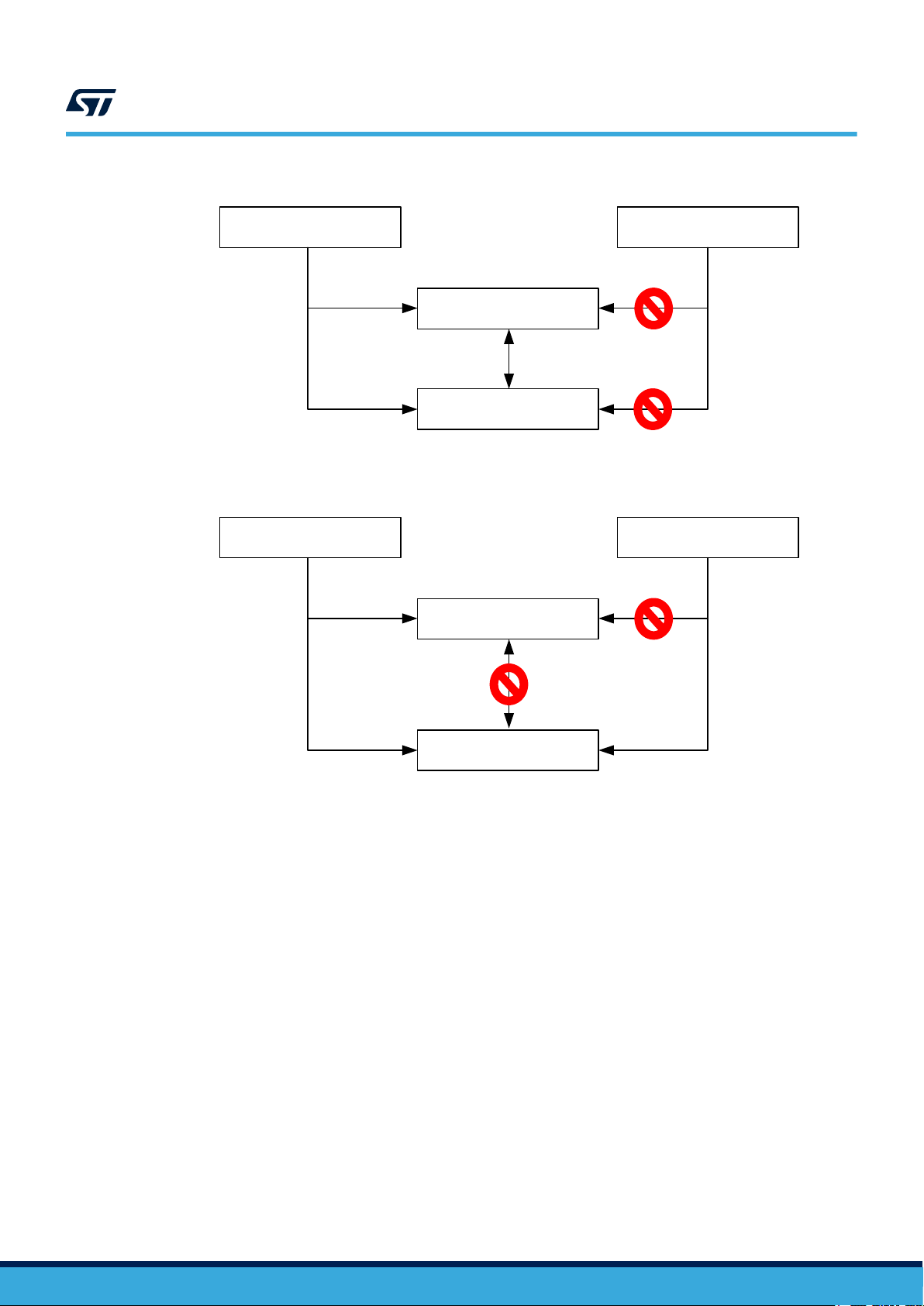
Figure 1. Secure UART connection to I/O allowed when the I/O is secure.
Secure access Non-secure access
Secure UART
Secure I/O
Figure 2. Secure UART connection to I/O not allowed when the I/O is non-secure.
Secure access Non-secure access
AN5600
4.2 I/Os with analog switches
When analog function with analog switch is used, the STM32L552xx and STM32L562xx add a secure gate on the
analog switch. This secure gate controls the switch opening/closing and allows blocking the connection between
the secure I/O and corresponding non-secure analog peripheral function.
Here, a different requirement applies to analog peripherals comparing to digital peripherals.
The goal is to prevent from capturing or corrupting pad level signals by using analog switches embedded in the
GPIO cells. A typical example is to use a non-secure ADC to capture serial data transiting on a secure I/O.
The analog functions concerned by this rule (for instance when an IO is secure and analog peripheral is nonsecure, the connection is blocked by hardware) are the following:
Secure UART
Non-secure I/O
AN5600 - Rev 1
page 6/17
Page 7

AN5600
I/Os used for additional functions with direct connections to peripherals
Table 3. Access rules when the I/O is used as ADC/OPAMP/COMP input
Peripheral Analog function
ADCx (x = 1,2) ADC12_INy (y = 1..16)
OPAMPx (x = 1,2) OPAMPx_VINy (x = 1,2, y = 1,2)
COMPx (x = 1,2) COMPx_INy (x = 1,2; y = 1,2)
Table 4. Blocked connection between non-secure ADC/OPAMP/COMP and corresponding secure I/Os
Security configuration
Peripheral Allocated I/O
Secure
Non-secure Zero
Secure
Non-secure
Figure 3. Blocked connection between non-secure ADC/OPAMP/COMP and corresponding secure I/Os
Secure
Non-secure I/O data
Input
I/O data
Connection blocked
ADCx Iny
by hardware
OPAMPx VINy
COMPx INy
Non secure analog peripheral
Secure I/O
4.3 I/Os used for additional functions with direct connections to peripherals
There are some direct connections between peripherals and I/Os additional functions that do not have a hardware
protection and to which the user must pay attention.
Unsuitable configuration can result in leaking information from secure resource or causing malfunction of secure
application.
For inputs there is the risk of secrets leakage.
For outputs there is more a risk to make the application fail.
To address this potential issue, it is up to the secure application to decide to configure these peripherals as secure
even if they are not used by a secure application.
Table 5 summarizes the list of peripherals and I/Os connections that do not have a hardware protection linked to
TrustZone®. Especially the listed signals (input and/or outputs) are not blocked when the I/O is set as secure and
the associated peripheral is non-secure.
AN5600 - Rev 1
page 7/17
Page 8

AN5600
I/Os used for additional functions with direct connections to peripherals
Table 5. Direct connection between peripheral and I/O, with no protection
Peripheral Signal I/O Input Output
DAC
PVD PVD_IN - x -
RTC
TSC
TAMP
PWR WKUPx, x = 1..5 PA0, PC13, PE6, PA2, PC5 - -
RCC LSCO PA2 - x
UCPD1
EXTI EXTIx, x = 0..15 All I/Os x -
DAC1_OUT1 PA4 - X
DAC1_OUT2 PA5 - X
RTC_OUT1 PC13 - X
RTC_OUT2 PB2 - X
RTC_TS PC13 x -
RTC_REFIN PB15 - -
TSC_G1_IOy PB12, PB13, PB14 x -
TSC_G2_IOy PB4, PB5, PB6, PB7 x -
TSC_G3_IOy PC10, PC11, PC12 x -
TSC_G4_IOy PC6, PC7, PC8, PC9 x -
TSC_G5_IOy PE10, PE11, PE12, PE13 x -
TSC_G6_IOy PD10, PD11, PD12, PD13 x -
TSC_G7_IOy PE2, PE3, PE4, PE5 x -
TSC_G8_IOy PF14, PF15, PG0, PG1 x -
TAMP_INx, x = 1..8
TAMP_OUTx, x = 1..8 - x
UCPD1_CC1 PA15 x x
UCPD1_DB1 PB5 x -
UCPD1_CC2 PB15 x x
UCPD1_DB2 PB14 x -
PE6, PC13, PF7, PF8, PF9, PA0, PA1, PC5
x -
AN5600 - Rev 1
Figure 4. Allowed connection between some specific non-secure signals and corresponding secure I/Os
DAC1_OUTx
PVD_IN
RTC_OUTx
RTC_TS
Connection is not blocked
by hardware
RTC_REFIN
TSC_Gx_IOy
TAMP_INx
TAMP_OUTx
WKUPx
Secure I/O
LSCO
UCPD1_CCx
UCPD1_DBx
EXTIx
Non secure peripherals/functionalities
page 8/17
Page 9

AN5600
I/Os used for additional functions with direct connections to peripherals
Caution: When an I/O is secure and it is used with a secure digital peripheral, some considerations are to be considered
when we have some non-secure specific functions on this I/O. These specific functions are summarized in the
Table 5. Direct connection between peripheral and I/O, with no protection.
4.3.1 Examples
When secure application sets PA4 as secure to be used as LPTIM2_OUT, if the DAC peripheral is non-secure, it
can be programmed to output data to PA4, potentially causing malfunction to the secure application.
When secure application sets PA0 as secure to be used as UART4_TX, if the TAMP peripheral is non-secure it
can be programmed to capture the USART input traffic through the TAMP_IN signal.
The touch sense I/Os are grouped in groups of three or four IOs as shown in the Table 5. Direct connection
between peripheral and I/O, with no protection.
For every I/O, the touch sense peripheral could enable the analog switch and I/Os can be connected. So, it is
possible to read secure I/O data with a non-secure I/O.
Consequently, depending on the application and criticality of secure information leaked to the non-secure world
or non-secure information injected to the secure world, the DAC, TAMP, TSC peripherals should be configured as
secure even they are not used by the application.
AN5600 - Rev 1
page 9/17
Page 10
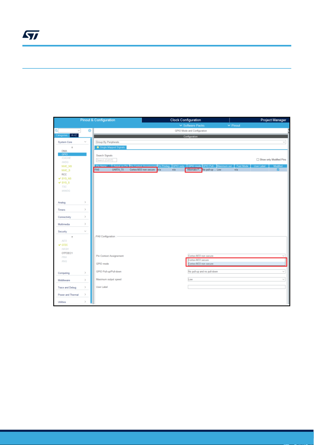
5 Basic example based on CubeMX
In the example, PA0 is used as UART4_TX.
When PA0 is configured for UART4_TX alternate function, with UART4 is non-secure (default state), it is still
possible to configure PA0 as secure or non-secure as shown in the figure below:
Figure 5. UART4 non-secure, PA0 secure/non-secure
AN5600
Basic example based on CubeMX
AN5600 - Rev 1
Now, the UART4 is configured as secure through GTZC:
page 10/17
Page 11

AN5600
Basic example based on CubeMX
Figure 6. UART4 secure through GTZC
Once UART4 is configured as secure through GTZC, it is no more possible to configure PA0 as non-secure. This
is because it is not possible to connect a secure peripheral to a non-secure I/O.
Figure 7. No more possible to configure PA0 as non-secure
AN5600 - Rev 1
page 11/17
Page 12

6 Conclusion
The STM32L5 Series provides a complete and cost-effective hardware security solution, which is used to
enhance the security level of a typical IoT end node device. This is thanks to the hardware security features set it
provides and hardware protections it implements preventing the non-secure world to accede secure information or
to cause secure application trouble.
In the STM32L5 devices, based on the peripheral security attribute, the corresponding I/O security attribute
follows some rules:
• Some paths between peripherals and I/Os are protected by hardware, so even if the secure application
doesn’t implement the right configuration, there is no risk to leak information to non-secure world or to
receive wrong information from the non-secure world that may cause application malfunction.
• At the same time, there are some other paths between peripherals and I/Os that don’t have any hardware
protection.
• Consequently, it is up to the secure application to setup the right configuration.
So, despite the embedded protection mechanism provided inside the STM32L5, it is recommended that the
application firmware configures in a consistent and coherent way the security state of each peripheral and its
associated GPIO.
AN5600
Conclusion
AN5600 - Rev 1
page 12/17
Page 13

Revision history
Date Revision Changes
28-Jan-2021 1 Initial release.
AN5600
Table 6. Document revision history
AN5600 - Rev 1
page 13/17
Page 14

AN5600
Contents
Contents
1 General information ...............................................................2
2 Security levels.....................................................................3
3 I/O security ........................................................................4
4 STM32L5 I/Os access rules when TrustZone is enabled.............................5
4.1 I/Os used as alternate function...................................................5
4.2 I/Os with analog switches........................................................6
4.3 I/Os used for additional functions with direct connections to peripherals.................7
4.3.1 Examples ..............................................................9
5 Basic example based on CubeMX .................................................10
6 Conclusion .......................................................................12
Revision history .......................................................................13
Contents ..............................................................................14
List of tables ..........................................................................15
List of figures..........................................................................16
AN5600 - Rev 1
page 14/17
Page 15

AN5600
List of tables
List of tables
Table 1. Threat models ......................................................................3
Table 2. Access Rules when the I/O is used as alternate function ........................................ 5
Table 3. Access rules when the I/O is used as ADC/OPAMP/COMP input ................................... 7
Table 4. Blocked connection between non-secure ADC/OPAMP/COMP and corresponding secure I/Os ..............7
Table 5. Direct connection between peripheral and I/O, with no protection ...................................8
Table 6. Document revision history ............................................................. 13
AN5600 - Rev 1
page 15/17
Page 16

AN5600
List of figures
List of figures
Figure 1. Secure UART connection to I/O allowed when the I/O is secure. .................................. 6
Figure 2. Secure UART connection to I/O not allowed when the I/O is non-secure. ............................6
Figure 3. Blocked connection between non-secure ADC/OPAMP/COMP and corresponding secure I/Os............. 7
Figure 4. Allowed connection between some specific non-secure signals and corresponding secure I/Os ............8
Figure 5. UART4 non-secure, PA0 secure/non-secure............................................... 10
Figure 6. UART4 secure through GTZC ........................................................ 11
Figure 7. No more possible to configure PA0 as non-secure .......................................... 11
AN5600 - Rev 1
page 16/17
Page 17

AN5600
IMPORTANT NOTICE – PLEASE READ CAREFULLY
STMicroelectronics NV and its subsidiaries (“ST”) reserve the right to make changes, corrections, enhancements, modifications, and improvements to ST
products and/or to this document at any time without notice. Purchasers should obtain the latest relevant information on ST products before placing orders. ST
products are sold pursuant to ST’s terms and conditions of sale in place at the time of order acknowledgement.
Purchasers are solely responsible for the choice, selection, and use of ST products and ST assumes no liability for application assistance or the design of
Purchasers’ products.
No license, express or implied, to any intellectual property right is granted by ST herein.
Resale of ST products with provisions different from the information set forth herein shall void any warranty granted by ST for such product.
ST and the ST logo are trademarks of ST. For additional information about ST trademarks, please refer to www.st.com/trademarks. All other product or service
names are the property of their respective owners.
Information in this document supersedes and replaces information previously supplied in any prior versions of this document.
© 2021 STMicroelectronics – All rights reserved
AN5600 - Rev 1
page 17/17
 Loading...