

Page 1

UM2611
User manual
Artificial Intelligence (AI) and computer vision function pack
for STM32H7 microcontrollers
Introduction
FP-AI-VISION1 is a function pack (FP) demonstrating the capability of STM32H7 Series microcontrollers to execute a
Convolutional Neural Network (CNN) efficiently in relation to computer vision tasks. FP-AI-VISION1 contains everything needed
to build a CNN-based computer vision application on STM32H7 microcontrollers.
FP-AI-VISION1 also demonstrates several memory allocation configurations for the data involved in the application. Each
configuration enables the handling of specific requirements in terms of amount of data required by the application. Accordingly,
FP-AI-VISION1 implements examples describing how to place the different types of data efficiently in both the on-chip and
external memories. These examples enable the user to understand easily which memory allocation fits his requirements the
best.
This user manual describes the content of the FP-AI-VISION1 function pack and details the different steps to be carried out in
order to build a CNN-based computer vision application on STM32H7 microcontrollers.
UM2611 - Rev 3 - September 2020
For further information contact your local STMicroelectronics sales office.
www.st.com
Page 2

1 General information
The FP-AI-VISION1 function pack runs on the STM32H7 microcontrollers based on the Arm® Cortex®-M7
processor.
Note: Arm is a registered trademark of Arm Limited (or its subsidiaries) in the US and/or elsewhere.
1.1 FP-AI-VISION1 function pack feature overview
• Runs on the STM32H747I-DISCO board connected with the STM32F4DIS-CAM camera daughterboard
• Includes three image classification application examples based on CNN:
– One food recognition application operating on color (RGB 24 bits) frame images
– One person presence detection application operating on color (RGB 24 bits) frame images
– One person presence detection application operating on grayscale (8 bits) frame images
• Includes complete application firmware for camera capture, frame image preprocessing, inference execution
and output post-processing
• Includes examples of integration of both floating-point and 8-bit quantized C models
• Supports several configurations for data memory placement in order to meet application requirements
• Includes test and validation firmware in order to test, debug and validate the embedded application
• Includes capture firmware enabling dataset collection
•
Includes support for file handling (on top of FatFS) on external microSD™ card
UM2611
General information
UM2611 - Rev 3
page 2/50
Page 3

1.2 Software architecture
The top-level architecture of the FP-AI-VISION1 function pack usage is shown in Figure 1.
UM2611
Software architecture
Figure 1. FP-AI-VISION1 architecture
Applications
(food recognition, person presence detection)
STM32_AI_Runtime
(Neural Network runtime library)
STM32_AI_Utilities
(Optimized routines)
Middleware level
STM32_Fs
(FatFS abstraction)
Board support package
(BSP)
Drivers
Hardware components
STM32_Image
(Image processing library)
FatFS
(Light FAT file system)
Hardware abstraction layer
(HAL)
STM32 LCDCamera sensor
STM32H747I-DISCOSTM32F4DIS-CAM
1.3
UM2611 - Rev 3
Development boards
Terms and definitions
Table 1 presents the definitions of the acronyms that are relevant for a better contextual understanding of this
document.
Table 1. List of acronyms
Acronym Definition
API Application programming interface
BSP Board support package
CNN Convolutional Neural Network
DMA Direct memory access
FAT File allocation table
page 3/50
Page 4

Acronym Definition
FatFS Light generic FAT file system
FP Function pack
FPS Frame per second
HAL Hardware abstraction layer
LCD Liquid crystal display
MCU Microcontroller unit
microSD
MIPS Million of instructions per second
NN Neural Network
RAM Random access memory
QVGA Quarter VGA
SRAM Static random access memory
VGA Video graphics array resolution
™
Micro secure digital
UM2611
Overview of available documents and references
1.4 Overview of available documents and references
Table 2 lists the complementary references for using FP-AI-VISION1.
Table 2. References
ID Description
User manual:
[1]
Getting started with X-CUBE-AI Expansion Package for Artificial Intelligence (AI) (UM2526).
Reference manual:
[2]
STM32H745/755 and STM32H747/757 advanced Arm
MobileNets: Efficient Convolutional Neural Networks for Mobile Vision Applications:
[3]
https://arxiv.org/pdf/1704.04861.pdf
The Food-101 Data Set:
[4]
https://data.vision.ee.ethz.ch/cvl/datasets_extra/food-101/
STM32CubeProgrammer software for programming STM32 products:
[5]
STM32CubeProg
Keras - The Python Deep Learning library:
[6]
https://keras.io/
STM32Cube initialization code generator:
[7]
STM32CubeMX
®
-based 32-bit MCUs (RM0399).
UM2611 - Rev 3
page 4/50
Page 5

UM2611
Building a CNN-based computer vision application on STM32H7
2 Building a CNN-based computer vision application on STM32H7
Figure 2 illustrates the different steps to obtain a CNN-based computer vision application running on the
STM32H7 microcontrollers.
Figure 2. CNN-based computer vision application build flow
network.c/h
network_data.c/h
FLOAT
model
32-bit
floating-point
C code
Build
float
C model
Quantization tool
STM32Cube.AI
Runtime
library
STM32H7
drivers
Image
preprocessing library
Main framework
fp_vision_app.c/h
img_preprocess.c/h
main.c/h
Neural Network
runtime library
QUANTIZED
model
network.c/h
network_data.c/h
8-bit
integer
C code
Build
quantized
C model
Legend:
CNN float
CNN quantized
Generated library
Computer vision application on STM32H7
Other libraries
Ecosystem & tools
Starting from a floating-point CNN model (designed and trained using a framework such as Keras), the user
generates an optimized C code (using the STM32Cube.AI tool, [1]) and integrates it in a computer vision
framework (provided as part of FP-AI-VISION1) in order to build his computer vision application on STM32H7.
Note: For users having selected a dual-core MCU like the STM32H747 for their application but running it on the
Cortex®-M7 core only: STM32CubeMX does not support the addition of packages like the STM32Cube.AI (X-
CUBE-AI) to the project. As a consequence, when using STM32CubeMX along with STM32Cube.AI, a single-
core MCU like the STM32H743 must be selected to be able to generate the Neural Network code for the
Cortex®-M7 core.
The user has the possibility to select one of two options for generating the C code:
• Either generating the floating-point C code directly from the CNN model in floating-point
• Or quantizing the floating-point CNN model to obtain an 8-bit model, and subsequently generating the
corresponding quantized C code
UM2611 - Rev 3
page 5/50
Page 6

UM2611
Integration of the generated code
For most CNN models, the second option enables to reduce the memory footprint (Flash and RAM) as well as
inference time. The impact on the final output accuracy depends on the CNN model as well as on the quantization
process (mainly the test dataset and the quantization algorithm).
As part of the FP-AI-VISION1 function pack, three image classification application examples are provided
including the following material:
• One food recognition application:
– Floating–point Keras model (.h5 file)
– 8-bit quantized model (.h5 file + .json file) obtained using STM32Cube.AI (X-CUBE-AI) quantizer
– Generated C code in both floating point and 8-bit quantized format
– Example of computer vision application integration based on C code generated by STM32Cube.AI (X-
CUBE-AI)
• Two person presence detection applications:
– 8-bit quantized models (.tflite file) obtained using the TFLiteConverter tool
– Generated C code in 8-bit quantized format
– Examples of computer vision application integration based on C code generated by STM32Cube.AI (X-
CUBE-AI)
1. TensorFlow is a trademark of Google Inc.
(1)
2.1 Integration of the generated code
From a float or quantized model, the user must use the STM32Cube.AI tool (X-CUBE-AI) to generate the
corresponding optimized C code.
When using the GUI version of STM32Cube.AI (X-CUBE-AI) with the user's own .ioc file, the following set of
files is generated in the output directory:
• Src\network.c and Inc\network.h: contain the description of the CNN topology
• Src\network_data.c and Inc\network_data.c: contain the weights and biases of the CNN
Note: For the network, the user must keep the default name, which is “network”. Otherwise, the user must rename all
the functions and macros contained in files ai_interface.c and ai_interface.h. The purpose of the ai_
interface.c and ai_interface.h files is to provide an abstraction interface to the NN API.
From that point, the user must copy and replace the above generated .c files and .h files respectively into the
following directories:
• \Projects\STM32H747I-DISCO\Applications\<app_name>\CM7\Src
<app_name> is any of
– FoodReco_MobileNetDerivative\Float_Model
– FoodReco_MobileNetDerivative\Quantized_Model
– PersonDetection\Google_Model
– PersonDetection\MobileNetv2_Model
• \Projects\STM32H747I-DISCO\Applications\<app_name>\CM7\Inc
<app_name> is any of
– FoodReco_MobileNetDerivative\Float_Model
– FoodReco_MobileNetDerivative\Quantized_Model
– PersonDetection\Google_Model
– PersonDetection\MobileNetv2_Model
UM2611 - Rev 3
An alternate solution is to use the CLI (command-line interface) version of STM32Cube.AI (X-CUBE-AI), so that
the generated files be directly copied into the Src and Inc directories contained in the output directory provided
on the command line. This solution does not require any manual copy/paste operation.
page 6/50
Page 7

UM2611
Integration of the generated code
The application parameters are configured in files fp_vision_app.c and fp_vision_app.h where they can
be easily adapted to the user's needs.
In file fp_vision_app.c:
• The output_labels[] table of strings (where each string corresponds to one output class of the Neural
Network model) is the only place where adaptation is absolutely required for a new application.
• The App_Context_Init() function is in charge of initializing the different software components of the
application. Some changes may be required to:
– adapt the camera orientation
– adapt the path to read input images from the microSD™ card when in Onboard Validation mode
– adapt to the NN input data range used during the training phase
– adapt the pixel color format of the NN input data
In file fp_vision_app.h:
• The two following #define must absolutely be updated with the dimensions of the NN input tensor:
– AI_NETWORK_WIDTH
– AI_NETWORK_HEIGHT
UM2611 - Rev 3
page 7/50
Page 8

3 Package content
3.1 CNN model
The FP-AI-VISION1 function pack is demonstrating two CNN-based image classification applications:
• A food-recognition application recognizing 18 types of food and drink
• A person presence detection application identifying whether a person is present in the image or not
3.1.1 Food recognition application
The food-recognition CNN is a derivative of the MobileNet model (refer to [3]).
MobileNet is an efficient model architecture [3] suitable for mobile and embedded vision applications. This model
architecture was proposed by Google®.
The MobileNet model architecture includes two simple global hyper-parameters that efficiently trade off between
latency and accuracy. Basically these hyper-parameters allow the model builder to determine the application rightsized model based on the constraints of the problem.
The food recognition model that is used in this FP has been built by adjusting these hyper-parameters for an
optimal trade-off between accuracy, computational cost and memory footprint, considering the STM32H747 target
constraints.
The food-recognition CNN model has been trained on a custom database of 18 types of food and drink:
• Apple pie
• Beer
• Caesar salad
• Cappuccino
• Cheesecake
• Chicken wings
• Chocolate cake
Coke
™
•
• Cupcake
• Donut
• French fries
• Hamburger
• Hot dog
• Lasagna
• Pizza
• Risotto
• Spaghetti bolognese
• Steak
The food-recognition CNN is expecting color image of size 224 × 224 pixels as input, each pixel being coded on
three bytes: RGB888.
The FP-AI-VISION1 function pack includes two examples based on the food recognition application: one example
implementing the floating-point version of the generated code, and one example implementing the quantized
version of the generated code.
UM2611
Package content
3.1.2 Person presence detection application
Two person presence detection applications are provided in this package:
• One based on a low-complexity CNN model (so-called Google_Model) working on grayscale images (8 bits
per pixel) with a resolution of 96 × 96 pixels. The model is downloaded from storage.googleapis.com.
• One based on a higher-complexity CNN model (so-called MobileNetv2_Model) working on color images
(24 bits per pixel) with a resolution of 128 × 128 pixels.
The person presence detection models contain two output classes: Person and Not Person.
The FP-AI-VISION1 function pack demonstrates 8-bit quantized models.
UM2611 - Rev 3
page 8/50
Page 9

3.2 Software
3.2.1 Folder organization
Figure 3 shows the folder organization in FP-AI-VISION1 function pack.
UM2611
Software
Figure 3. FP-AI-VISION1 folder tree
FLOAT
model
32-bit
floating-point
C code
Quantization tool
STM32Cube.AI
Generated code:
network.c/h
network_data.c/h
QUANTIZED
model
8-bit
integer
C code
UM2611 - Rev 3
Legend:
CNN float
CNN quantized
Ecosystem & tools
Driver
Contains all the BSP and STM32H7 HAL source code.
page 9/50
Page 10

Middlewares
Contains five sub-folders:
• ST/STM32_AI_Runtime
The lib folder contains the Neural Network runtime libraries generated by STM32Cube.AI (X-CUBE-AI) for
each IDE: IAR Embedded Workbench® from IAR Systems (EWARM), MDK-ARM from Keil®, and
STM32CubeIDE from STMicroelectronics. These libraries do not need to be replaced when converting a
new Neural Network.
The Inc folder contains the include files required by the runtime libraries.
These two folders do not need to be replaced when converting a new Neural Network, unless using a new
version of the X-CUBE-AI code generator.
• ST/STM32_AI_Utilities
Contains optimized routines.
• ST/STM32_Image
Contains a library of functions for image processing. These functions are used to preprocess the input frame
image captured by the camera. The purpose of this preprocessing is to generate the adequate data (such as
size, format, and others) to be input to the Neural Network during the inference.
• ST/STM32_Fs
Contains a library of functions for handling image files using FatFS on a microSD™ card.
• Third_Party/FatFS
Third party middleware providing support for FAT file system.
UM2611
Software
Project/STM32H747I-DISCO/Applications
Contains the projects and source codes for the applications provided in the FP-AI-VISION1 FP. These
applications are running on the STM32H747 (refer to [2]), which is a dual-core microcontroller based on the
Cortex®-M7 and Cortex®-M4 processors. The application code is running only on the Cortex®-M7 core.
Project/STM32H747I-DISCO/Applications/Common
This folder contains the source code common to all applications:
• ai_interface.c and ai_interface.h
Provide an abstraction of the NN API.
• fp_vision_ai.c and fp_vision_ai.h
Provide the utilities that are required to adapt the representation of the NN input data, post-process the NN
output data, initialize the NN, and run an inference of the NN. These files require to be adapted by the user
for application parameters when integrating a new Neural Network model.
• fp_vision_camera.c and fp_vision_camera.h
Provide the functions to configure and manage the camera module.
• fp_vision_display.c and fp_vision_display.h
Provide the functions to configure and manage the LCD display.
• fp_vision_preproc.c and fp_vision_preproc.h
Provide an abstraction layer to the image preprocessing library (located in Middlewares/ST/STM32_Imag
e).
• fp_vision_test.c and fp_vision_test.h
Provide a set of functions for testing, debugging and validating the application.
• fp_vision_utils.c and fp_vision_utils.h
Provide a set of miscellaneous utilities.
UM2611 - Rev 3
page 10/50
Page 11

UM2611
Software
Project/STM32H747I-DISCO/Applications/FoodReco_MobileNetDerivative
This folder contains all the source code related to the food recognition application. It contains two sub-folders, one
sub-folder per application example:
• One demonstrating the integration of the float C model (32-bit float C code)
• One demonstrating the integration of the quantized C model (8-bit integer C code)
Each sub-folder is composed as follows:
• Binary
Contains the binaries for the applications:
– STM32H747I-DISCO_u_v_w_x_y_z.bin
Binaries generated from the source files contained in the Float_Model/CM7 and Quantized_Model
/CM7 folders.
◦ u corresponds to the application name. For the food recognition application, the value is:
• Food
◦ v corresponds to the model type. For the food recognition application, it can be:
• Std (for standard)
• Optimized (for optimized)
When v is Opt, it means that the binary is generated from sources that are not released as part of
the FP-AI-VISION1 function pack since they are generated from a specific version of the food
recognition CNN model. This specific version of the model is further optimized for a better tradeoff between accuracy and embedded constraints such as memory footprint and MIPS. Contact
STMicroelectronics for information about this specific version.
◦ w corresponds to the data representation of the model type. For the food recognition application, it
can be:
• Float (for float 32 bits)
• Quant8 (for quantized 8 bits)
◦ x corresponds to the configuration for the volatile data memory allocation. For the food
recognition application, it can be:
• Ext (for external SDRAM)
• Split (for split between internal SRAM and external SDRAM)
• IntMem (for internal SRAM with memory optimized)
• IntFps (for internal SRAM with FPS optimized)
◦ y corresponds to the memory allocation configurations for the non-volatile data. For the food
recognition application, it can be:
• IntFlash (for internal Flash memory)
• QspiFlash (for external Q-SPI Flash memory)
• ExtSdram (for external SDRAM)
◦ z corresponds to the version number of the FP-AI-VISION1 release. It is expressed as Vabc
where a, b and c represent the major version, minor version, and patch version numbers
respectively. For the food recognition application corresponding to this user manual, the value is:
• V200
UM2611 - Rev 3
page 11/50
Page 12

• CM7
Contains the source code specific to the food recognition application example that is executed on the
Cortex®-M7 core. There are two types of files:
– Files that are generated by the STM32Cube.AI tool (X-CUBE-AI):
◦ network.c and network.h: contain the description of the CNN topology
◦ network_data.c and network_data.h: contain the weights and biases of the CNN
– Files that contain the application:
◦ main.c and main.h
◦ fp_vision_app.c and fp_vision_app.h
Used to configure the application specific settings.
◦ stm32h7xx_it.c and stm32h7xx_it.h
Implement the interrupt handlers.
• CM4
This folder is empty since all the code of the food recognition application is running on the Cortex®-M7 core.
• Common
Contains the source code that is common to the Cortex®-M7 and Cortex®-M4 cores.
• EWARM
Contains the IAR Systems IAR Embedded Workbench® workspace and project files for the application
example. It also contains the startup files for both cores.
• MDK-ARM
Contains the Keil® MDK-ARM workspace and project files for the application example. It also contains the
startup files for both cores.
• STM32CubeIDE
Contains the STM32CubeIDE workspace and project files for the application example. It also contains the
startup files for both cores.
Note: For the EWARM, MDK-ARM and STM32CubeIDE sub-folders, each application project may contain several
configurations. Each configuration corresponds to:
• A specific data placement in the volatile memory (RAM)
• A specific placement of the weight-and-bias table in the non-volatile memory (Flash)
UM2611
Software
Project/STM32H747I-DISCO/Applications/PersonDetection
This folder contains the source code that is specific to the person presence detection applications. It contains two
sub-folders, one sub-folder per application example:
• One demonstrating the integration of a low-complexity model (so-called Google_Model)
• One demonstrating the integration of a medium-complexity model (so-called MobileNetv2_Model)
The organization of sub-folders is identical to the one of the sub-folders described above in the context of the food
recognition application examples.
UM2611 - Rev 3
page 12/50
Page 13

UM2611
Software
The Binary sub-folder contains the binaries for the applications. The binaries are named as STM32H747I-DISC
O_u_v_w_x_y_z.bin where:
• u corresponds to the application name. For the person presence detection applications, the value is:
– Person
• v corresponds to the model type. For the person presence detection applications, it can be:
– Google
– MobileNetV2
• w corresponds to the data representation of the model type. For the person presence detection applications,
the value is:
– Quant8 (for quantized 8 bits)
• x corresponds to the memory allocation configurations for the volatile data. For the person presence
detection applications, the value is:
– IntFps (for internal SRAM with FPS optimized)
• y corresponds to the memory allocation configurations for the non-volatile data. For the person presence
detection applications, the value is:
– IntFlash (for internal Flash memory)
• z corresponds to the version number of the FP-AI-VISION1 release. It is expressed as Vabc where a, b and
c represent the major version, minor version, and patch version numbers respectively. For the person
presence detection application corresponding to this user manual, the value is:
– V200
Utilities/AI_resources/Food-Recognition
This sub-folder contains:
• The original trained model (file FoodReco_MobileNet_Derivative_Float.h5) for the food recognition
CNN used in the application examples. This model is used to generate:
– Either directly the floating-point C code via STM32Cube.AI (X-CUBE-AI)
– Or the 8-bit quantized model via the quantization process, and then subsequently the integer C code
via STM32Cube.AI (X-CUBE-AI)
• The files required for the quantization process (refer to Section 3.2.2 Quantization process):
– config_file_foodreco_nn.json: file containing the configuration parameters for the quantization
operation
– test_set_generation_foodreco_nn.py: file containing the function used to prepare the test
vectors used in the quantization process
• The quantized model generated by the quantization tool (files FoodReco_MobileNet_Derivative_Qua
ntized.json and FoodReco_MobileNet_Derivative_Quantized.h5)
• The re-training script (refer to ): FoodDetection.py along with a Jupyter™ notebook (FoodDetection.i
pynb)
• A script (create_dataset.py) to convert a dataset of images in the format expected by the piece of
firmware performing the validation on board (refer to Onboard Validation mode in Section 3.2.8 Embedded
validation, capture and testing)
Utilities/AI_resources/PersonDetection
This sub-folder contains:
• MobileNetv2_Model/README.md: describes how to retrain a new person detection image classifier from
a pre-trained network using TensorFlow™.
• MobileNetv2_Model/create_dataset.py: Python™ script to create the ***Person20*** dataset
from the previously downloaded COCO dataset as described in the README.md file.
• MobileNetv2_Model/train.py: Python™ script to create an image classifier model from a pre-trained
MobileNetV2 head.
UM2611 - Rev 3
page 13/50
Page 14

UM2611
Software
• MobileNetv2_Model/quantize.py: Python™ script to perform post-training quantization on a Keras
model using the TFLiteConverter tool from TensorFlow™. Sample images are required to run the
quantization operation.
3.2.2 Quantization process
The quantization process consists in quantizing the parameters (weights and biases) as well as the activations of
a NN in order to obtain a quantized model having parameters and activations represented on 8-bit integers.
Quantizing a model reduces the memory footprint because weights, biases, and activations are on 8 bits instead
of 32 bits in a float model. It also reduces the inference execution time through the optimized DSP unit of the
Cortex®-M7 core.
Several quantization schemes are supported by the STM32Cube.AI (X-CUBE-AI) tool:
• Fixed point Qm,n
• Integer arithmetic (signed and unsigned)
Refer to the STM32Cube.AI tool (X-CUBE-AI) documentation in [1] for more information on the different
quantization schemes and how to run the quantization process.
Note: • Two datasets are required for the quantization operation. It is up to the user to provide his own datasets.
• The impact of the quantization on the accuracy of the final output depends on the CNN model (that is its
topology), but also on the quantization process: the test dataset and the quantization algorithm have a
significant impact on the final accuracy.
3.2.3 Training scripts
Training scripts are provided for each application.
3.2.3.1 Food recognition application
File Utilities/AI_ressources/Food-Recognition/FoodDetection.ipynb contains an example script
showing how to train the MobileNet derivative model used in the function pack. As the dataset used to train the
model provided in the function pack is not publicly available, the training script relies on a subset of the Food-101
dataset (refer to [4]). This publicly available dataset contains images of 101 food categories with 1000 images per
category.
In order to keep the training process short, the script uses only 50 images per food category, and limits the
training of the model to 20 epochs. To achieve a training on the whole dataset, the variable
max_imgs_per_class in section Prepare the test and train datasets must be updated to np.inf.
Note: The use of the GPU is recommended for the complete training on the whole dataset.
The Jupyter™ notebook is also available as a plain Python™ script in the Utilities/AI_ressources/Food-R
ecognition/FoodDetection.py file.
3.2.3.2 Person presence detection application
File Utilities/AI_ressources/PresenceDetection/MobileNetv2_Model/train.py contains an
example script showing how to retrain the MobileNetV2 model by using transfer learning. The training script relies
on the ***Person20*** dataset. Instructions on how to build the ***Person20*** dataset from the publiclyavailable COCO-2014 dataset can be found in Utilities/AI_resources/PersonDetection/MobileNetv
2_Model/README.md along with the Utilities/AI_resources/PersonDetection/MobileNetv2_Mode
l/create_dataset.py Python™ script to filter COCO images. An example Python™ script to perform post-
training quantization is available in Utilities/AI_resources/PersonDetection/MobileNetv2_Model/q
uantize.py. The post-training quantization is performed on a Keras model using the TFLiteConverter tool from
TensorFlow™. Sample images are required to run the quantization operation. Sample images can be extracted
from the model training set.
UM2611 - Rev 3
page 14/50
Page 15

3.2.4 Memory requirements
When integrating a C model generated by the STM32Cube.AI (X-CUBE-AI) tool, the following memory
requirements must be considered:
• Volatile (RAM) memory requirement: memory space is required to allocate:
– The inference working buffer (called the activation buffer in this document). This buffer is used
during inference to store the temporary results of the intermediate layers within the Neural Network.
– The inference input buffer (called the nn_input buffer in this document), which is used to hold the
input data of the Neural Network.
• Non-volatile (Flash) memory requirement: memory space is required to store the table containing the
weights and biases of the network model.
On top of the above-listed memory requirements, some more requirements come into play when integrating the C
model for a computer vision application:
• Volatile (RAM) memory requirement: memory space is required in order to allocate the various buffers that
are used across the execution of the image pipeline (camera capture, frame pre-processing).
UM2611
Software
UM2611 - Rev 3
page 15/50
Page 16

3.2.4.1 Application execution flow and volatile (RAM) data memory requirement
In the context of a computer vision application, the integration requires several data buffers as illustrated in
Figure 4. Section 3.2.4.1 shows the different data buffers required during the execution flow of the application.
Figure 4. Data buffers during execution flow
Initialization phase
UM2611
Software
Start first frame capture
Frame capture
completed?
Memory copy
Start next frame capture
Image resizing
Pixel color format conversion
(PFC)
DMA
memcpy
DMA
Image
resizing
(*)
DMA2D
or
SW
R
W
R
W
R
W
R
W
R
W
DCMI data register
camera_capture buffer
camera_capture buffer
camera_frame buffer
DCMI data register
camera_capture buffer
camera_frame buffer
Resize_Dst_Img buffer
Resize_Dst_Img buffer
Pfc_Dst_Img buffer
Pixel format adaptation
Neural Network inference
Legend:
R: read operation
W: write operation
(*): Also swaps red and
blue pixel components
if necessary.
Format
adaptation
Neural
Network
inference
HW operation SW operation
Occurs in all memory allocation configurations except in the
“Full internal, memory optimized (Int_Mem)” configuration,
in which case the camera_capture and camera_frame
buffers are the same.
RAM data memory
R
W
R
R/W
W
Occurs where shown, except when in the
“Full internal, memory optimized (Int_Mem)”
configuration, in which case it occurs after NN
inference completion.
Pfc_Dst_Img buffer
nn_input buffer
nn_input buffer
activation (= working) buffer
nn_output buffer
Peripheral register memory
UM2611 - Rev 3
page 16/50
Page 17

UM2611
Software
The application executes the following operations in sequence:
1. Acquisition of the camera frame (via the DMA engine from DCMI data register) in the camera_capture
buffer. After acquisition completion, the content of the camera_capture buffer is copied into the LCD frame
buffer (not shown in Table 3 and always located in the external SDRAM) via the DMA2D engine with the
transformation from the RGB565 capture format to the ARGB8888 display format.
2. At this point, depending on the memory allocation configuration chosen, the camera_capture buffer
content is copied onto the camera_frame buffer and the capture of the subsequent frame is launched.
3. Rescale the image contained in the camera_frame buffer into the Resize_Dst_Img buffer to match the
expected CNN input tensor dimensions. For instance, the food recognition NN model requires an input
tensor such as Height × Width = 224 × 224 pixels.
4. Perform pixel color format conversion and red blue color channel swapping (either via DMA2D hardware or
software routine) from the Resize_Dst_Img buffer into the Pfc_Dst_Img buffer. For instance, in the food
recognition example, the RGB565 capture format is converted to the RGB888 format to provide the three
input channels expected by the food recognition CNN model.
5. Adapt the format of each pixel contained in the Pfc_Dst_Img buffer content into the nn_input buffer. The
adaptation consists in changing the representation of each pixel to fit with the range defined by the NN
model training and the quantization format expected by a quantized NN.
6. Run inference of the NN model: the nn_input buffer as well as the activation buffer are provided as
input to the NN. The results of the classification are stored into the nn_output buffer.
7. Post-process the nn_output buffer content and display the results on the LCD display.
The activation buffer is the working buffer used by the NN during the inference. Its size depends on the NN
model used.
Note: The activation buffer size is provided by the STM32Cube.AI tool (X-CUBE-AI) when analyzing the NN (refer
to Section 3.2.4.1 for an example).
The nn_output buffer is where the classification output results are stored. For instance, in the food recognition
NN provided in the FP-AI-VISION1 function pack, the size of this buffer is 18 × 4 = 72 bytes: 18 corresponds to
the number of output classes and 4 corresponds to the fact that the probability of each output class is provided as
a float value (single precision, coded on 4 bytes).
UM2611 - Rev 3
page 17/50
Page 18

UM2611
Table 3 details the amount of data RAM required by the food recognition applications when integrating the
quantized C model or the float C model.
Table 3. SRAM memory buffers for food recognition applications
Software
SRAM data buffer
SRAM data buffer size (byte)
Food recognition CNN
Quantized C model Float C model
camera_capture
camera_frame
Resize_Dst_Img
Pfc_Dst_Img
nn_input
activation
nn_output
Name Pixel format
16 bits
(RGB565)
16 bits
(RGB565)
16 bits
(RGB565)
24 bits
(RGB888)
(1)
24 bits
(RGB888)
(1)
- 98 K 395 K
-
VGA capture
(640 × 480)
600 K
(640 × 480 × 2)
600 K
(640 × 480 × 2)
(224 × 224 × 3)
(18 × 4)
QVGA capture
(320 × 240)
(320 × 240 × 2)
(320 × 240 × 2)
147 K
72
150 K
150 K
(224 × 224 × 2)
(224 × 224 × 3)
VGA capture
(640 × 480)
(640 × 480 × 2)
(640 × 480 × 2)
98 K
147 K
600 K
600 K
588 K
(224 × 224 × 3 × 4)
72
(18 × 4)
QVGA capture
(320 × 240)
150 K
(320 × 240 × 2)
150 K
(320 × 240 × 2)
1. When generating the C code with the STM32Cube.AI tool: if the “allocate input in activation” option is selected (either via the
--allocate-inputs option in the CLI or via the “Use activation buffer for input buffer” checkbox in the advanced
settings of the GUI), STM32Cube.AI overlays the nn_input buffer with the activation buffer;it might result in a bigger
activation size. However in this case the nn_input buffer is not required any longer. In the end, the overall amount of
memory required is reduced. In the given food recognition quantized C model, when the “allocate input in activation” is
selected, the size of the generated activation buffer is ~148 Kbytes, which is bigger than 98 Kbytes but lower than
245 Kbytes (98 + 147). Regarding the given food recognition float C model: the “allocate input in activation” option is not
selected since the nn_input buffer (which size is equal to 588 Kbytes) does not fit in internal SRAM.
UM2611 - Rev 3
page 18/50
Page 19

UM2611
Software
Table 4 details the amount of data RAM required by the presence detection applications when integrating the
MobileNetV2 model or the Google model.
Table 4. SRAM memory buffers for person presence detection applications
SRAM data buffer
SRAM data buffer size (byte)
Person presence detection CNN
MobileNetV2 model Google model
Name
QVGA capture
(320 × 240)
camera_capture
camera_frame
Resize_Dst_Img
Pfc_Dst_Img
nn_input
activation
(1)
(1)
(320 × 240, 16-bit RGB565)
(320 × 240, 16-bit RGB565)
(128 × 128, 16-bit RGB565)
(128 × 128, 24-bit RGB888)
(128 × 128, 24-bit RGB888)
nn_output
150 K
(320 × 240, 16-bit RGB565)
150 K
(320 × 240, 16-bit RGB565)
32 K
(96 × 96, 16-bit RGB565)
48 K
(96 × 96, 8-bit grayscale)
48 K
(96 × 96, 8-bit grayscale)
197 K 37 K
8
(2 × 4)
150 K
150 K
18 K
9 K
9 K
8
(2 × 4)
1. When generating the C code with the STM32Cube.AI tool: if the “allocate input in activation” option is selected (either via the
--allocate-inputs option in the CLI or via the “Use activation buffer for input buffer” checkbox in the advanced
settings of the GUI), STM32Cube.AI overlays the nn_input buffer with the activation buffer; it might result in a bigger
activation size. However in this case the nn_input buffer is not required any longer. In the end, the overall amount of
memory required is reduced. In the given Google quantized C model, when the “allocate input in activation” is selected, the
size of the generated activation buffer is 37 Kbytes, which is lower than 46 Kbytes (37 + 9).
UM2611 - Rev 3
page 19/50
Page 20

3.2.4.2 STM32H747 internal SRAM
Table 5 represents the internal SRAM memory map of the STM32H747XIH6 microcontroller:
Memory Address range Size (Kbyte)
DTCM RAM 0x2000 0000 ‑ 0x2001 FFFF 128
Reserved 0x2002 0000 ‑ 0x23FF FFFF -
AXI SRAM 0x2400 0000 ‑ 0x2407 FFFF 512
Reserved 0x2400 8000 ‑ 0x2FFF FFFF -
SRAM1 0x3000 0000 ‑ 0x3001 FFFF 128
SRAM2 0x3002 0000 ‑ 0x3003 FFFF 128
SRAM3 0x3004 0000 ‑ 0x3004 7FFF 32
Reserved 0x3004 8000 ‑ 0x37FF FFFF -
SRAM4 0x3800 0000 ‑ 0x3800 FFFF 64
Reserved 0x3801 0000 ‑ 0x387F FFFF -
BCKUP SRAM 0x3880 0000 ‑ 0x3880 0FFF 4
Total - 1 Mbyte
UM2611
Software
Table 5. STM32H747XIH6 SRAM memory map
The STM32H747XIH6 features about 1 Mbyte of internal SRAM. However, it is important to note that:
• This 1 Mbyte is not a contiguous memory space. The largest block of SRAM is the AXI SRAM, which has a
size of 512 Kbytes.
• The nn_input buffer must be placed in a continuous area of memory. This is the same for the
activation buffer. As a result, the basic following rule applies: if either the nn_input buffer or the
activation buffer is larger than 512 Kbytes, the generated C model is not able to execute by relying only
on the internal SRAM. In this case, additional external data RAM is required.
3.2.4.3 Buffer placement in volatile (RAM) data memory
The comparison of the sizes in Table 3, Table 4 and Table 5 leads to the following conclusions regarding the
integration of the C models for the different application examples provided in the FP-AI-VISION1 FP:
• Regarding the food recognition application, the float C model implementation does not fit completely into the
internal SRAM, whatever the camera resolution selected: some external RAM is required in order to run this
use case.
Concerning the implementation of the quantized C model:
– If the VGA camera resolution is selected, the implementation does not fit completely into the internal
SRAM. Some external RAM is required to run this use case.
– If the QVGA camera resolution is selected, the implementation fits completely into the internal SRAM.
No external RAM is required.
• Regarding the person presence detection application, all the example implementations provided fit
completely into the internal SRAM. No external RAM is required.
UM2611 - Rev 3
page 20/50
Page 21

UM2611
Software
In the context of the FP-AI-VISION1 FP, two memory allocation configurations are supported for the
implementations that do not entirely fit into the STM32 internal SRAM:
• Full External (Ext) memory allocation configuration: consists in placing all the buffers (listed in Table 3) in the
external SDRAM.
• Split External/Internal (Split) memory allocation configuration: consists in placing the activation buffer
(which includes the nn_input buffer if the allocate input in activation option in selected in the
STM32Cube.AI (X-CUBE-AI) tool) as well as the Resize_Dst_Img and Pfc_Dst_Img buffers (since in the
current version of the FP, both buffers are by design overlaid with the activation buffer) in the internal
SRAM and the camera_capture and camera_frame buffers in the external SDRAM. The nn_input
buffer is also placed in the external SDRAM (like in the food recognition float C model for instance), unless
its size is such that it enables the nn_input buffer to be overlaid with the activation buffer (via the
selection of the allocate input in activation option).
Choosing one configuration or the other comes down to the following trade-off:
• Release as much internal SRAM as possible so that it is available for other user applications possibly
requiring a significant amount of internal SRAM
• Reduce the inference time by having the working buffer (activation buffer) allocated in faster memory
such as the internal SRAM
In the context of the FP-AI-VISION1 FP, two memory allocation configurations are supported for the
implementations that do entirely fit into the STM32 internal SRAM:
• Full internal, memory optimized (Int_Mem) memory allocation configuration: consists in placing all the
buffers listed in Table 3 or Table 4 in internal memory. The placement is such that it enables the SRAM
occupation optimization.
• Full internal, frame per second optimized (Int_Fps) memory allocation configuration: consists in placing all
the buffers listed in Table 3 or Table 4 in internal memory. The placement is such that it enables the
optimization of the number of frames processed per second.
Section 3.2.4.4 Optimizing the internal SRAM memory space describes in details the Full internal, memory
optimized and Full internal, frame per second optimized memory allocation configurations.
3.2.4.4 Optimizing the internal SRAM memory space
For the use case fitting integrally in the internal SRAM, two memory allocation schemes are supported with a view
to optimizing the internal SRAM memory space as much as possible.
These two memory allocation schemes rely on the allocate input in activation feature offered by the
STM32Cube.AI tool (X-CUBE-AI) with a view to optimize the space required for the activation and nn_input
buffers: basically, the nn_input buffer is allocated within the activation buffer, making both buffer “overlaid”.
(Refer to [1] for more information on how to enable these optimizations when generating the Neural Network C
code.)
First memory allocation scheme: Full internal, memory optimized (Int_Mem)
A single and unique physical memory space is allocated for all the buffers: camera_capture, camera_frame,
Resize_Dst_Img, Pfc_Dst_Img , nn_input, nn_output and activation buffers. In other words, these
seven buffers are “overlaid”, which means that a unique physical memory space is used for seven different
purposes during the application execution flow.
The size of this memory space is equal to the size of the largest among the activation buffer and the
camera_frame buffer. For instance, in the food recognition quantized model in QVGA, the size of this memory
space is equal to the size of the camera_frame buffer amounting to 150 Kbytes.
The advantage of this approach is that the required memory space is optimized at best.
This approach has also two main drawbacks:
• The data stored in the memory space are overwritten (and thus no longer available) as the application is
moving forward along the execution flow.
• The memory space is not available for a new camera capture until the NN inference is completed. As a
consequence, the maximum number of frames that can be processed per second is not optimized.
UM2611 - Rev 3
page 21/50
Page 22

The whole amount of memory required is allocated in a single region as illustrated in Figure 5.
Figure 5. SRAM allocation - Memory optimized scheme
UM2611
Software
R
Image
rescaling
Pixel color
format
conversion
(**)
W
R
Pixel
format
adaptation
W
@ = lower address
DCMI
data
register
R
DMA
camera_frame
buffer
W
W
(*)
Resize_Dst_Img
buffer
R
Pfc_Dst_Img
buffer
nn_input
buffer
activation
buffer
R
R/W
Neural
Network
inference
@ = higher address
(***)
W
nn_output
buffer
Application execution flow
Notes:
(*): When in Full internal, memory optimized allocation configuration, the camera_capture and camera_frame buffers are one single and unique buffer since
the subsequent capture starts only after the NN inference is completed.
(**): The pixel color format conversion can be performed either in hardware via the DMA2D or in software.
(***): higher address = lower address + Max(activation buffer size, camera_frame buffer size)
Legend:
R: read operation
W: write operation
HW
operation
SW
operation
Peripheral register memory SRAM data memory
nn_input
allocated in activation
Note: By enabling the memory optimization feature in the STM32Cube.AI tool (“allocate input in activation”), only
148 Kbytes of memory are required to hold both the activation and the nn_input buffers (versus
147 Kbytes + 98 Kbytes = 245 Kbytes if this feature is not enabled).
Second memory allocation scheme: Full internal, frame per second optimized (Int_Fps)
• A first physical memory space is allocated only for the camera_capture buffer. The advantage of this
approach is that a subsequent frame can be captured as soon as the content of the camera_capture
buffer is copied onto the camera_frame buffer without waiting for the inference to complete. As a result, the
number of frames processed per second is optimal.
This is at the expense of the amount of memory space required.
• A second unique physical memory space is allocated for all the other buffers: camera_frame,
Resize_Dst_Img, Pfc_Dst_Img, nn_input, nn_output and activation buffers. In other words,
these six buffers are “overlaid”, which means that a unique physical memory space is used for six different
purposes during the application execution flow.
The size of this memory space is equal to the size of the biggest of the five “overlaid” buffers: in our case, it
is the largest among the activation and camera_frame buffers. For instance, in the food recognition
quantized model in QVGA, the size of this memory space is equal to the size of the camera_frame buffer,
amounting to 150 Kbytes.
UM2611 - Rev 3
page 22/50
Page 23

UM2611
Software
Conclusion: The overall memory size required by the second allocation scheme is
150 Kbytes + 150 Kbytes = 300 Kbytes. The amount of memory required by the second scheme is higher than the
one in the first scheme but the second scheme enables to optimize the number of frames processed per second.
The whole amount of memory required is allocated in a single region as illustrated in Figure 6.
Figure 6. SRAM allocation - FPS optimized scheme
DCMI
data
register
R
DMA
R
DMA
W
camera_capture
buffer
R
memcpy
W
@ = lower
address
W
R
camera_frame
buffer
Image
rescaling
W
Resize_Dst_Img
buffer
Pixel color
format
conversion
(*)
R
W
Pfc_Dst_Img
buffer
R
Pixel
format
adaptation
W
nn_input
buffer
R
Neural
Network
activation
buffer
R/W
inference
W
@ = higher
address
(**)
nn_output
buffer
Application execution flow
Notes:
(*): The pixel color format conversion can be performed either in hardware via the DMA2D or in software.
(**): higher address = lower address + camera_frame buffer size + Max(activation buffer size, camera_frame buffer size)
Legend:
R: read operation
W: write operation
HW
operation
SW
operation
Peripheral register memory SRAM data memory
allocated in activation
Note: By enabling the memory optimization feature in the STM32Cube.AI tool (“allocate input in activation”), only
148 Kbytes of memory are required to hold both the activation and the nn_input buffers (versus
147 Kbytes + 98 Kbytes = 245 Kbytes if this feature is not enabled).
UM2611 - Rev 3
nn_input
page 23/50
Page 24

3.2.4.5 Weight and bias placement in non-volatile (Flash) memory
The STM32Cube.AI (X-CUBE-AI) code generator generates a table (defined as constant) containing the weights
and biases. Therefore, by default, the weights and biases are stored into the internal Flash memory.
There are use cases where the table of weights and biases does not fit into the internal Flash memory (the size of
which being 2 Mbytes, shared between read-only data and code). In such situation, the user has the possibility to
store the weight-and-bias table in the external Flash memory.
The STM32H747I-DISCO Discovery board supported in the context of this FP has a serial external Flash that is
interfaced to the STM32H747I MCU via a Quad-SPI. An example illustrating how to place the weight-and-bias
table in the external Flash memory is provided in this FP under Projects/STM32H747I-DISCO/Application
s/FoodReco_MobileNetDerivative/Float_Model directory (configurations STM32H747I-DISCO_FoodRe
co_Float_Ext_Qspi, STM32H747I-DISCO_FoodReco_Float_Split_Qspi, STM32H747I-DISCO_FoodRe
co_Float_Split_Sdram and STM32H747I-DISCO_FoodReco_Float_Ext_Sdram).
Follow the steps below to load the weight-and-bias table in the Q-SPI external Flash memory:
1. Define flags WEIGHT_QSPI to 1 and WEIGHT_QSPI_PROGED to 0 to define a memory placement section in
the memory range corresponding to the Quad-SPI memory interface (0x9000 0000) and place the table of
weights and biases into it.
In order to speed up the inference, it is possible for the user to set flag WEIGHT_EXEC_EXTRAM to 1 (as
demonstrated for instance in configurations STM32H747I-DISCO_FoodReco_Float_Split_Sdram and S
TM32H747I-DISCO_FoodReco_Float_Ext_Sdram) so that the weight-and-bias table gets copied from
the external Q-SPI Flash memory into the external SDRAM memory at program initialization.
UM2611
Software
UM2611 - Rev 3
page 24/50
Page 25

UM2611
Software
2. Generate a binary of the whole application as an .hex file (not as a .bin file). Load the .hex file using the
STM32CubeProgrammer (STM32CubeProg) tool [5]. Select first the external Flash loader for the
STM32H747I-DISCO Discovery board. As shown in Figure 7, the user must select the External loaders tab
on the left to access the External loaders view. After selecting the right Flash loader, the user must select the
Erasing & programming tab on the left to access the Erasing & programming view shown on Figure 8.
Figure 7 and Figure 8 are snapshots of the STM32CubeProgrammer (STM32CubeProg) tool showing the
sequence of steps to program the full binary of the application into the Flash memory.
Figure 7. Flash programming (1 of 2)
2
Select the Flash loader for the
STM32H747I-DISCO Discovery board
1
Select the External loaders tab
UM2611 - Rev 3
page 25/50
Page 26

Figure 8. Flash programming (2 of 2)
UM2611
Software
3
4
Load the binary into the target memory
Browse for the binary (.hex) of the full application
3. Once the table of weights and biases is loaded into the external memory, it is possible to continue the
debugging through the IDE by defining flag WEIGHT_QSPI_PROGED to 1
Defining flag WEIGHT_QSPI to 0 generates a program with the weight-and-bias table located in the internal
Flash memory.
Table 6 summarizes the combinations of the compile flags.
Table 6. Compile flags
Compile flag
Effect
WEIGHT_QSPI
WEIGHT_QSPI
_PROGED
WEIGHT_EXEC
_EXTRAM
UM2611 - Rev 3
Generates a binary with the weight-and-bias table placed in the
Generates a binary with the
weight-and-bias table placed in
the external Q-SPI Flash
memory
Generates a binary without the
weight-and-bias table (since
already loaded)
1. To be loaded using the STM32CubeProgrammer tool (STM32CubeProg).
internal Flash memory
(1)
memory into the external SDRAM
memory into the external SDRAM
- 1 0 0
Weight-and-bias table copied
from the external Q-SPI Flash
at startup
- 1 1 0
Weight-and-bias table copied
from the external Q-SPI Flash
at startup
0 0 0
0 0 1
0 1 0
0 1 1
1 0 1
1 1 1
page 26/50
Page 27

Refer to Section 3.2.5 Execution performance for the performance when the weight-and-bias table is accessed
from the external Q-SPI Flash memory and external SDRAM versus internal Flash memory.
When generating new C code from a new model, the usual way to do (as described in Section 2.1 Integration of
the generated code) is to replace the existing network.c, network.h, network_data.c and network_data
.h files by the ones generated. If placement in external memory is required, the existing network_data.c file
must not be replaced. Instead, it is requested to replace only the content of the weight-and-bias table (named s_n
etwork_weights[]) contained in the existing network_data.c file by the content of the table contained in the
generated network_data.c file.
3.2.4.6 Summary of volatile and non-volatile data placement in memory
The FP-AI-VISION1 function pack demonstrates the implementation of four different schemes for allocating the
volatile data in memory:
• Full internal memory with FPS optimized (Int_Fps):
All the buffers (listed in Table 3 and Table 4) are located in the internal SRAM. To enable the whole system
to execute from the internal memory, some memory buffers are overlaid (as shown in Figure 6).
In this memory layout scheme, the camera_capture buffer is not overlaid so that it enables a new camera
capture while the inference is running, hence maximizing the number of frames per second (FPS).
• Full internal memory with memory optimized (Int_Mem):
All the buffers (listed in Table 3 and Table 4) are located in the internal SRAM. In order to enable the whole
system to execute from the internal memory, some memory buffers are overlaid (as shown in Figure 5).
In this memory layout scheme, the camera_capture and camera_frame buffers are one and single
unique buffer, which is overlaid so that it optimizes the internal SRAM occupation as much as possible.
• Full external memory (Ext):
All the buffers (listed in Table 3 and Table 4) are located in the external SDRAM.
• Split internal / external memory (Split):
The camera_capture and camera_frame buffers are located in the external SDRAM. The activation
buffer (which includes the nn_input buffer if the allocate input in activation option is selected in the
STM32Cube.AI (X-CUBE-AI) tool) as well as the Resize_Dst_Img and Pfc_Dst_Img buffers (since in the
current version of the FP, both buffers are by design overlaid with the activation buffer), are located in
the internal SRAM. In this allocation scheme, the nn_input buffer is also placed in the external SDRAM
(like in the food recognition float C model for instance), unless its size is such that it enables the nn_input
buffer to be overlaid with the activation buffer (via the selection of the allocate input in activation option).
UM2611
Software
The FP-AI-VISION1 function pack also demonstrates the implementation of three different ways to access (at
inference time) the non-volatile data stored in memory:
• Access from the internal Flash memory
• Access from the external Q-SPI Flash memory
• Access from the external SDRAM: in this case the non-volatile data are stored either in the internal Flash
memory or in the external Q-SPI Flash memory and are copied into the external SDRAM at program startup
UM2611 - Rev 3
page 27/50
Page 28

UM2611
Software
Table 7 lists the IAR Embedded Workbench® projects available in FP-AI-VISION1 with the various configurations.
Table 7. Summary of IAR Embedded Workbench® project configurations versus memory schemes
IAR Embedded Workbench® project configuration
name
STM32H747I-DISCO_FoodReco_Float_Ext
STM32H747I-DISCO_FoodReco_Float_Ext_Qspi External Q-SPI Flash memory
STM32H747I-DISCO_FoodReco_Float_Ext_Sdram External SDRAM
STM32H747I-DISCO_FoodReco_Float_Split
STM32H747I-DISCO_FoodReco_Float_Split_Qspi External Q-SPI Flash memory
STM32H747I-DISCO_FoodReco_Float_Split_Sdram External SDRAM
STM32H747I-DISCO_FoodReco_Quantized_Ext Full external
STM32H747I-DISCO_FoodReco_Quantized_Split Split internal / external
STM32H747I-DISCO_FoodReco_Quantized_Int_Mem
STM32H747I-DISCO_FoodReco_Quantized_Int_Fps
STM32H747I-DISCO_PersonDetect_MobileNetv2
Memory allocation scheme for
volatile data
Full external
Split internal / external
Full internal with memory
optimized
Full internal with FPS optimizedSTM32H747I-DISCO_PersonDetect_Google
Memory used to store the
weights and biases
Internal Flash memory
Internal Flash memory
Internal Flash memory
UM2611 - Rev 3
page 28/50
Page 29

3.2.5 Execution performance
Table 8 and Table 9 present the camera capture time and preprocessing time measured for both the food
recognition and person presence detection applications.
Table 8. Measurements of frame capture and preprocessing times for the food recognition application
Measurements
(ms)
Camera frame capture time
Image rescaling time
Pixel color conversion
Pixel format adaptation time
1.
Measurement conditions: STM32H747 at 400 MHz CPU clock, code compiled with EWARM v8.40.2 with option -O3.
2. The values depend on the lighting conditions since the exposure time may vary.
3. Values for the OV9655 module of the STM32F4DIS-CAM camera daughterboard connected with the STM32H747I-DISCO
Discovery board.
4. In the FP-AI-VISION1, the “Nearest Neighbor” algorithm is used as the rescaling method. The memory locations of the
camera_capture and Resize_Dest_Img buffers have an impact on the timing.
5. The memory locations of the Resize_Dest_Img and Pfc_Dest_Img buffers have an impact on the timing.
6. A pre-computed look-up table is used for the pixel format adaptation when dealing with the quantized model. The memory
locations of the Pfc_Dest_Img and nn_input buffers have an impact on the timing.
(2) (3)
(4)
(5)
(6)
UM2611
Software
examples
Food recognition
(1)
VGA capture (640 × 480)
Quantized C model Float C model Quantized C model
~65 ~35
~5 to ~7 ~5
< 1 to ~2 < 1
~1 to ~3 ~9 to ~11 ~1
QVGA capture
(320 × 240)
Table 9. Measurements of frame capture and preprocessing times for the person presence detection
application examples
Person presence detection
Measurements
(ms)
(1)
MobileNetV2 model
(128 × 128, 24-bit RGB888)
Camera frame capture time
Image rescaling time
Pixel color conversion
Pixel format adaptation time
1.
Measurement conditions: STM32H747 at 400 MHz CPU clock, code compiled with EWARM v8.40.2 with option -O3.
(2) (3)
(4)
(5)
(6)
~2 ~1
QVGA capture (320 × 240)
Google model
(96 × 96, 8-bit grayscale)
~35
< 1
< 1
2. The values depend on the lighting conditions since the exposure time may vary.
3. Values for the OV9655 module of the STM32F4DIS-CAM camera daughterboard connected with the STM32H747I-DISCO
Discovery board.
4. In the FP-AI-VISION1, the “Nearest Neighbor” algorithm is used as the rescaling method.
5. The memory locations of the Resize_Dest_Img and Pfc_Dest_Img buffers have an impact on the timing.
6. A pre-computed look-up table is used for the pixel format adaptation when dealing with the quantized model.
Considering the different possible models (float and quantized), the different possible camera resolutions (VGA
and QVGA), the different possible locations for data in volatile memory (full external, split, full internal FPS
optimized, full internal memory optimized), and the different possible locations of the weight-and-bias table during
inference execution (internal Flash memory, external Q-SPI Flash memory, external SDRAM), the number of
possible configuration is high.
UM2611 - Rev 3
page 29/50
Page 30

UM2611
Software
Table 10 and Table 11 summarize the configurations supported in the FP-AI-VISION1 function pack for both the
food recognition and person presence detection applications.
Table 10. Configurations supported by the FP-AI-VISION1 function pack for the food recognition
applications
Food recognition
Volatile memory
layout scheme
Full internal
Memory optimized
Full internal
FPS optimized
Full external
Split
external/internal
Weight-and-bias
table location
Internal Flash memory
External SDRAM Not supported
Internal Flash memory
External Q-SPI Flash memory Not supported
External SDRAM Not supported
Internal Flash memory YES
External SDRAM Not supported YES
Internal Flash memory YES
External SDRAM Not supported YES
Quantized C model Float C model
VGA capture
(640 × 480)
Not possible
Not possible
QVGA capture
(320 × 240)
YES
YES
Not supported
Not supported
VGA capture
(640 × 480)
Not possible Not possibleExternal Q-SPI Flash memory Not supported
Not possible Not possible
YES
YES
QVGA capture
(320 × 240)
Not supportedExternal Q-SPI Flash memory Not supported YES
Not supportedExternal Q-SPI Flash memory Not supported YES
Table 11. Configurations supported by the FP-AI-VISION1 function pack for the person presence detection
applications
Volatile memory
layout scheme
Full internal
Memory optimized
Full internal
FPS optimized
Full external
Split
external/internal
Weight-and-bias
table location
Internal Flash memory
External Q-SPI Flash memory
External SDRAM
Internal Flash memory YES YES
External Q-SPI Flash memory
External SDRAM
Internal Flash memory
External SDRAM
Internal Flash memory
External SDRAM
MobileNetV2 model Google model
Person presence detection
NO NO
NO NO
NO NOExternal Q-SPI Flash memory
NO NOExternal Q-SPI Flash memory
The values provided in Table 12 and Table 13 below result from measurements performed using application
binaries built with the EWARM IDE.
UM2611 - Rev 3
page 30/50
Page 31

UM2611
Software
Table 12 presents the execution performance of the food recognition applications with the following conditions:
• IAR Systems EWARM v8.40.2
• -O3 option
• Cortex®-M7 core clock frequency set to 400 MHz
Table 12. Execution performance of the food recognition application
C model
Float VGA
Quantized
1. FPS is calculated taking into account the capture, preprocessing, and inference times.
2.
IAR™ configuration > Binary file.
3. Food recognition CNN model quantized using the quantization tool (provided by the STM32Cube.AI tool v5.1.2) with the
“UaUa per layer” quantization scheme.
Camera
resolution
VGA
(3)
QVGA
Volatile memory
layout scheme
Full external
Split
Full external
Split 79 11.8 H
Full internal
Memory optimized
Full internal
FPS optimized
Weight-and-bias
table location
Internal Flash
memory
Q-SPI external
Flash memory
External SDRAM 267 3.5 C
Internal Flash
memory
Q-SPI external
Flash memory
External SDRAM 243 3.9 F
Internal Flash
memory
NN
inference
time (ms)
250 3.7
283 3.3 B
227 4.1 D
261 3.6 E
97 9.2
79 8.5 I
79 11.8 J
Frames
processed
per second
(1)
(FPS)
Output
accuracy
(%)
~73
~72.5
Binary
file
(2)
A
G
UM2611 - Rev 3
The FPS values provided in Table 12 are max values. The FPS values can vary depending on the light conditions.
Indeed, the FPS value includes the inference time, but also the preprocessing and camera capture times (refer to
Table 8). The capture time depends on the light conditions via the exposure time.
The binary files, contained in the Binary folder, associated with the scenarios in Table 12, are listed below:
• A: STM32H747I-DISCO_FoodReco_Float_Ext > STM32H747I-DISCO_Food_Std_Float_Ext_IntF
lash_V200.bin
• B: STM32H747I-DISCO_FoodReco_Float_Ext_Qspi > STM32H747I-DISCO_Food_Std_Float_Ext
_QspiFlash_V200.hex
• C: STM32H747I-DISCO_FoodReco_Float_Ext_Sdram > STM32H747I-DISCO_Food_Std_Float_E
xt_ExtSdram_V200.hex
• D: STM32H747I-DISCO_FoodReco_Float_Split > STM32H747I-DISCO_Food_Std_Float_Split
_IntFlash_V200.bin
• E: STM32H747I-DISCO_FoodReco_Float_Split_Qspi > STM32H747I-DISCO_Food_Std_Float_S
plit_QspiFlash_V200.hex
• F: STM32H747I-DISCO_FoodReco_Float_Split_Sdram > STM32H747I-DISCO_Food_Std_Float_
Split_ExtSdram_V200.bin
• G: STM32H747I-DISCO_FoodReco_Quantized_Ext > STM32H747I-DISCO_Food_Std_Quant8_Ex
t_IntFlash_V200.bin
page 31/50
Page 32

UM2611
Software
• H: STM32H747I-DISCO_FoodReco_Quantized_Split > STM32H747I-DISCO_Food_Std_Quant8_
Split_IntFlash_V200.bin
• I: STM32H747I-DISCO_FoodReco_Quantized_Int_Mem > STM32H747I-DISCO_Food_Std_Quant8
_IntMem_IntFlash_V200.bin
• J: STM32H747I-DISCO_FoodReco_Quantized_Int_Fps > STM32H747I-DISCO_Food_Std_Quant8
_IntFps_IntFlash_V200.bin
Table 13 presents the execution performance of the recognition application generated from the optimized model
(not provided as part of the FP-AI-VISION1 function pack. Contact STMicroelectronics for information about this
specific version.) The measurement conditions are:
• IAR Systems EWARM v8.40.2
• -O3 option
•
Cortex®-M7 core clock frequency set to 400 MHz
Table 13. Execution performance of the optimized food recognition application
C model
Float VGA
Quantized
1. FPS is calculated taking into account the capture, preprocessing, and inference times.
2. Food recognition CNN model quantized using the quantization tool (provided by the STM32Cube.AI tool v5.1.2) with the
“UaUa per layer” quantization scheme.
Camera
resolution
VGA
(2)
QVGA
Volatile memory
layout scheme
Full external
Split Not possible
Full external 220 4.3
Split 145 6.6 M
Full internal
Memory optimized
Full internal
FPS optimized
Weight-and-bias
table location
Internal Flash
memory
NN
inference
time (ms)
503 1.9 ~78 K
145 5.4 N
145 6.6 O
Frames
processed
per second
(1)
(FPS)
Output
accuracy
(%)
~77.5
Binary
file
The binary files, contained in the Binary folder, associated with the scenarios in Table 13, are listed below:
• K: STM32H747I-DISCO_Food_Opt_Float_Ext_IntFlash_V200.bin
• L: STM32H747I-DISCO_Food_Opt_Quant8_Ext_IntFlash_V200.bin
• M: STM32H747I-DISCO_Food_Opt_Quant8_Split_IntFlash_V200.bin
• N: STM32H747I-DISCO_Food_Opt_Quant8_IntMem_IntFlash_V200.bin
• O: STM32H747I-DISCO_Food_Opt_Quant8_IntFps_IntFlash_V200.bin
L
UM2611 - Rev 3
The straight model (Table 12) shows better execution performance in some cases than the optimized model
(Table 13). However, this is at the expense of the accuracy, which is better when using the optimized model since
in both cases the CNN working buffer (activation buffer) is located in the internal SRAM.
page 32/50
Page 33

UM2611
Software
Table 14 presents the execution performance of the person presence detection applications with the following
conditions:
• IAR Systems EWARM v8.40.2
• -O3 option
• Cortex®-M7 core clock frequency set to 400 MHz
Table 14. Execution performance of the person presence detection application
C model
MobileNetV2
Google 41 23.3 87 Q
1. FPS is calculated taking into account the capture, preprocessing, and inference times.
2. Top-1 accuracy against ***Person20*** dataset.
3.
IAR™ configuration > Binary file.
Camera
resolution
QVGA Full internal
Volatile memory
layout scheme
Weight-and-bias
table location
Internal Flash
memory
NN
inference
time (ms)
174 5.7 92 P
Frames
processed
per second
(1)
(FPS)
Output
accuracy
(2)
(%)
Binary
(3)
file
The binary files, contained in the Binary folder, associated with the scenarios in Table 14, are listed below:
• P: STM32H747I-DISCO_PersonDetect_MobileNetv2 > STM32H747I-DISCO_Person_MobileNetv
2_Quant8_IntFps_IntFlash_V200.bin
• Q: STM32H747I-DISCO_PersonDetect_Google > STM32H747I-DISCO_Person_Google_Quant8_
IntFps_IntFlash_V200.bin
Note regarding the versions of the STM32Cube.AI library
The kernels of the v5.1.2 STM32Cube.AI (X-CUBE-AI) library are optimized to deal efficiently with the following
situations:
• Quantized model with activations located in internal SRAM
• Float model with weights located in external memory
As a consequence:
• When a quantized model is used: if activations are in external SDRAM, it is recommended to use version
5.0.0 of the STM32Cube.AI (X-CUBE-AI) library to obtain optimized inference time
• When a float model is used with weights located in internal Flash memory: it is recommended to use version
5.0.0 of the STM32Cube.AI (X-CUBE-AI) library to obtain optimized inference time
UM2611 - Rev 3
CNN impact on the final accuracy
As mentioned previously in Quantization process, the type of CNN has an impact on the final accuracy. This is
illustrated by the columns Ouput accuracy in Table 12 and Table 13:
• Table 12 contains numbers pertaining to a network which topology has been optimized in such a way to
reducing the inference time. However, this is at the expense of the output accuracy (accuracy drop of about
10 %).
• Table 13 provides numbers pertaining to a network which topology has been optimized in such a way to
optimize the output accuracy. As a result, Table 13 shows accuracies that are better than the ones shown in
Table 12. However, this is at the expense of the inference time and the memory space required by the
network (larger activation buffer and weight-and-bias table).
page 33/50
Page 34

3.2.6 Memory footprint
Table 15 presents the memory requirements for all the applications. The numbers in the table account neither for
the code and data related to the LCD display management nor for the code and data related to the test mode
implementations.
UM2611
Software
Table 15. Memory footprints per application
Application C model
Food Reco
Float standard
Food Reco
Float optimized
Food Reco
Quantized standard
Food Reco
Quantized optimized
Person Detect
MobileNetV2
Person Detect
Google
Camera
resolution
VGA
VGA
(4)
QVGA
VGA
(4)
QVGA
QVGA
Volatile data memory
configuration
Full external
Split ~420 K ~1.2 M
(1)
Code
RO data
~520 K
Internal
(2)
SRAM
~20 K ~1.6 M
(3)
~60 K
Full external ~590 K ~20 K ~2.0 M
Full external
~20 K
Split
Full internal
Memory optimized
Full internal
FPS optimized
Full external
Split
Full internal
Memory optimized
Full internal
FPS optimized
Full internal
FPS optimized
~140 K
~80 K
~160 K
~500 K ~390 K
~230 K ~320 K
~170 K
~320 K
~20 K
~240 K
~390 K
External
SDRAM
~1.2 M
0
~1.2 M
0
0
1. The “allocate input in activation” option is selected in the STM32Cube.AI tool for C code generation (except for the Food
Reco float models).
2. Includes the weight-and-bias table.
3. Includes the stack and heap size requirements.
4. Food recognition CNN model quantized using the quantization tool (provided by the STM32Cube.AI tool v5.1.2) with the
“UaUa per layer” quantization scheme.
Flash (byte) RW data (byte)
UM2611 - Rev 3
The external SDRAM also contains the two following items:
• Read and write buffers for managing the display on the LCD: total size of 16 Mbytes since each buffer (of
size 840 × 480 × 4 = 1.575 Mbytes) is placed in a separate SDRAM bank to optimize the SDRAM access
• The buffers used for the test mode implementation: total size of 5.4 Mbytes
The code size is different between the float and quantized models. This is due to the fact that both models do not
involve the same set of functions from the runtime library.
page 34/50
Page 35

UM2611
3.2.7 Visualization modes
3.2.7.1 Food recognition applications
The main application provides two visualization modes:
• A logo view, where each food category is represented by a logo
• An image view, which displays the camera feed
By default, the application starts with the logo view activated. Press the [WakeUp] button during the execution to
toggle between the modes.
Note: When pressing the [WakeUp] button, the user must wait for the message Entering/Exiting CAMERA
PREVIEW mode, Please release button to show up on the screen before releasing the button. Both
visualization modes also report the inference time (in ms), the number of frames per second (FPS) that are
processed, and the Top-1 output class probability (in %).
3.2.7.2 Person presence detection applications
For the person presence detection applications, only the camera image view mode is available. The captured
camera content is displayed along with the inference time (in ms), the number of processed frames per second
(FPS) and the Top-1 output class probability (in %). The person presence detection applications provide four
camera orientation modes:
• Normal
• Flipped image (default)
• Mirrored image
• Mirrored and flipped image
Pressing on the blue [WakeUp] button causes the camera sensor to cycle through the different camera orientation
modes listed above. This functionality can be used to place the camera in different orientations with respect to the
board LCD display.
Software
3.2.8 Embedded validation, capture and testing
The FP-AI-VISION1 function pack embeds the possibility to perform validation, capture and testing via specific
operating modes:
• Frame Capture mode: captures frames from the camera to a microSD™ card
• Memory Dump mode: dumps every step of the processing pipeline to a microSD™ card for debug
• Onboard Validation mode: evaluates the Neural Network with images stored in a microSD™ card
This section presents each of the three modes as well as the way to start each of them.
Prerequisite
The three modes require a microSD™ card to be plugged into the STM32H747I-DISCO Discovery board. It is
recommended to use at least a class 10 microSD™ card to avoid slow read/write operations. Moreover, the card
must be FatFS formatted and contain one single partition.
UM2611 - Rev 3
page 35/50
Page 36

UM2611
Software
Enabling the validation, capture and testing modes
Maintain the [WakeUp] button pressed during the welcome screen (after a reset) to enable the test menu shown
in Figure 9 instead of the main application.
Figure 9. Validation, capture and testing menu
Start the desired application by pressing the corresponding arrow key of the joystick:
• [UP]: the default application is started (Neural Network inference with images from the camera)
• [RIGHT]: the Frame Capture mode is started
• [LEFT]: the Memory Dump mode is started
• [DOWN]: the Onboard Validation mode is started
UM2611 - Rev 3
page 36/50
Page 37

Overview of Onboard Validation, Frame Capture and testing modes
Figure 10. Overview of validation, capture and testing modes
UM2611
Software
(16 bits per pixel, RGB565 color format, VGA or QVGA resolution)
Read a .bmp file stored
on the microSD™ card
Input frame source
Camera frame acquisition
camera_capture
Input frame resize
Resize_Dst_Img
Pixel color format
conversion
Pfc_Dst_Img
Pixel format adaptation
camera_frame_buff.bmp/raw
camera_frame_buff_xx.bmp/raw
resize_output_buff.bmp/raw
Memory Dump output file contents
(1) (2)
pfc_output_buff.bmp/raw
nn_input_buff.bmp/raw
nn_input
Neural Network inference
and output post process
nn_output
Notes:
(1) The example is based on the food recognition (quantized C model) application. In this specific example, the pixel color format
conversion (PFC) is configured (by the application) to swap the blue and red components for each pixel. This swap is required in this
specific case since the food recognition NN model is trained with images containing pixels in BGR format while the frames acquired
by the camera contain pixels in RGB format.
(2) The picture is extracted from The Food-101 Data Set.
Legend:
Write operation in Memory Dump mode
Write operation in Frame Capture mode
Write operation in Onboard Validation mode
nn_input_buff_xx.bmp/raw
nn_output_buff.txt
confusion_matrix.csv
Application execution step
Data memory buffer
Output file on microSD™ card
UM2611 - Rev 3
page 37/50
Page 38

UM2611
Software
Frame Capture mode
The main purpose of the Frame Capture application is to enable data collection. By default in the application, the
frame is captured at two stages:
• right after the camera acquisition (RGB565 format)
and
• after all the preprocessing stages, just before being fed to the input of the Neural Network
However, by modifying the application code, the frame can be captured at any stage of the execution chain. To do
so, set to 1 the PerformCapture field of the TestRunContext structure that is initialized before each stage of
the execution chain.
The format of the file into which the frame is captured can be configured with one of the formats below:
• .bmp file with data encoded in 16-bit pixel format (RGB565)
• .raw binary file format
This is configurable via the capture_file_format field of the CaptureContext structure during the
initialization of the Frame Capture mode. The default format is .bmp.
At the end, the captured frame is stored into the microSD™ card.
For the frame capture mode, the user can also choose to swap the red and blue components of the pixels before
writing the buffer content into the output file. This is done by setting to 1 the rb_swap field of the
TestRunContext structure.
At application startup, the Camera_Capture folder is created if not already existing and a session name is
generated and displayed in the top-left corner of the screen. A sub-folder, named CAM_CAPTURE_SESS_<sessio
n name>, is also created. The screen shows the image taken from the camera and in the top-right corner, the
READY message indicates that the program is ready to write to the microSD™ card.
To trigger a frame capture, press on the [WakeUp] button. The READY message switches to BUSY, indicating that
the frame is being written to the microSD™ card, preventing all other capture meanwhile. Once the write operation
is finished, the READY message is displayed and capture enabled again.
Each capture generates two files in the sub-folder corresponding to the session:
• camera_frame_buff_xx.bmp or camera_frame_buff_xx.raw: contains the frame captured right after
the camera acquisition, before the preprocessing stage.
• nn_input_buff_xx.bmp or nn_input_buff_xx.raw: contains the frame captured after the
preprocessing stage, before the input of the Neural Network.
For a given session, the xx filename postfix corresponds to the incremental capture number.
UM2611 - Rev 3
Memory Dump mode
The Memory Dump application is mainly intended for debug purposes. When entering this operating mode, the Me
mory_Dump folder is created if not already existing.
The screen shows the image contained in the camera_frame buffer and in the top-right corner, the READY
message indicates that the program is ready to start a memory dump session.
To trigger a memory dump session, press on the [WakeUp] button. The READY message switches to BUSY,
indicating that the memory dump operations are being performed and that writing to the microSD™ card is taking
place, preventing all other capture meanwhile. Similarly to the Frame Capture mode, a session name is generated
and displayed in the top-left corner of the screen. A sub-folder named DUMP_SESS_<session name> is also
created. Once the memory dump operations are completed, the READY message is displayed and memory dump
enabled again.
During a memory dump session, each execution stage of the application (as described in
Section 3.2.4.1 Application execution flow and volatile (RAM) data memory requirement) is followed by a dump
of the memory portion containing the output data. The memory content is dumped into files stored in the
microSD™ card. These files can be in one the following formats: .bmp, .raw or .txt.
page 38/50
Page 39

UM2611
Software
Each memory dump session generates five files in the sub-folder corresponding to the session:
• camera_frame_buff.bmp or camera_frame_buff.raw: camera_frame buffer content following
acquisition.
• resize_output_buff.bmp or resize_output_buff.raw: Resize_Dst_Img buffer content following
resizing operation.
• pfc_output_buff.bmp or pfc_output_buff.raw: Pfc_Dst_Img buffer content following pixel color
format conversion operation.
• nn_input_buff.bmp or nn_input_buff.raw: nn_input buffer content following pixel format
adaptation operation.
• nn_output_buff.txt: nn_ouput buffer content following Neural Network inference.
The memory dump mode has three sub-modes depending on the source of the input image:
•
SD card: the input image is coming from a .bmp file stored in the microSD™ card in a folder named dump_s
rc_image_xx, xx being the resolution of the image (possible values are: vga and qvga).
• Camera live: the input image is coming from the camera acquisition (like in the nominal operating mode).
• Test Color Bar: the input image is coming from the camera acquisition, the camera being configured in test
color bar mode.
The format of the file into which the memory content is dumped can be configured with one of the five formats
below:
• .bmp file format with data encoded in 8 bits per pixel
• .bmp file format with data encoded in 16 bits per pixel (RGB565)
• .bmp file format with data encoded in 24 bits per pixel (RGB888)
• .raw binary file format
• .txt file format
Figure 10 above shows an example of Memory Dump output files obtained when using the food recognition
quantized model in QVGA resolution. The output file obtained after the pixel color format conversion stage has
red and blue pixel components swapped. The reason for the swap is because the food recognition NN model
expects the memory layout of the input pixel with the blue component at address offset 0. However the camera
capture acquisition is providing frames with pixels organized with red components at address offset 0. A swap
between the red and blue pixel components is required so to feed the NN model with correct input data.
Onboard Validation mode
The Onboard Validation application uses images stored in the microSD™ card as inputs for evaluating the Neural
Network.
In order for the program to find the images in the microSD™ card, a directory named onboard_valid_dataset
_xx must exist at the root of the file system, xx being the resolution of the image (possible values are: vga and q
vga). Inside this directory, there must be one directory per class containing the images with the same name as
defined by NN_OUTPUT_CLASS_LIST in the code.
In the function pack, this variable is aliased to output_labels defined in file fp_vision_app.c. The following
example is given for the food recognition application:
#define NN_OUTPUT_CLASS_LIST output_labels
const char *output_labels[AI_NET_OUTPUT_SIZE] = {
"Apple Pie", "Beer", "Caesar Salad", "Cappuccino", "Cheesecake", "Chicken Wings", "Chocolate
Cake", "Coke", "Cup Cakes", "Donuts", "French Fries", "Hamburger", "HotDog", "Lasagna",
"Pizza", "Risotto", "Spaghetti Bolognese", "Steak"};
All images must be stored in the BMP format (16 bits per pixel) with a VGA or QVGA resolution. The class is
derived directly from the directory containing the images. The filenames are not considered.
A helper script (named create_dataset.py) to convert any dataset of images to the BMP format is provided in
the Utilities\AI_resources\Food-Recognition directory.
UM2611 - Rev 3
page 39/50
Page 40

For the food recognition example, the structure of the microSD™ file system must be as follows:
.
|-- onboard_valid_dataset_xx
|-- Apple Pie
| |-- apple_pie_example1.bmp
| |-- another_apple_pie.bmp
| `-- ...
|-- Beer
| |-- beer.bmp
| |-- another_beer.bmp
| `-- ...
|-- Caesar Salad
| |-- a_caesar_salad.bmp
| `-- ...
|-- Cappuccino
| |-- cappuccino.bmp
| `-- ...
|-- Cheesecake
| |-- cheesecake.bmp
| `-- ...
|-- Chicken Wings
| |-- chicken_wing.bmp
| `-- ...
|-- Chocolate Cake
| |-- chocolate_cake.bmp
| `-- ...
|-- Coke
| |-- coke.bmp
| `-- ...
|-- Cup Cakes
| |-- cup_cakes.bmp
| `-- ...
|-- Donuts
| |-- donuts.bmp
| `-- ...
|-- French Fries
| |-- french_fries.bmp
| `-- ...
|-- Hamburger
| |-- hamburger.bmp
| `-- ...
|-- Hot Dog
| |-- hot_dog.bmp
| `-- ...
|-- Lasagna
| |-- lasagna.bmp
| `-- ...
|-- Pizza
| |-- pizza.bmp
| `-- ...
|-- Risotto
| |-- risotto.bmp
| `-- ...
|-- Spaghetti Bolognese
| |-- spaghetti_bolognese.bmp
| `-- ...
`-- Steak
|-- steak.bmp
`-- ...
UM2611
Software
UM2611 - Rev 3
page 40/50
Page 41

UM2611
Software
At startup, the Onboard Validation application displays a summary of the information presented in this section.
Press the [WakeUp] button to start the validation. The screen shown in Figure 11 is then displayed.
Figure 11. Onboard Validation summary of information for a food recognition example
At the top of the display, the class name is presented with its index in NN_OUTPUT_CLASS_LIST.
The left side shows the current image being processed by the Neural Network, which is resized to match the
network input size. Below the image, the display shows the NN Top-1 output, the confidence level, and the
average categorical cross-entropy loss across all processed images.
The right side of the display shows the confusion matrix, that is constantly updated while images are being
processed by the neural network. The rows indicate the ground-truth label, and the columns the predicted class.
UM2611 - Rev 3
page 41/50
Page 42

UM2611
Software
When all images are processed, a message is displayed and a press on the [WakeUp] button updates the display
with a classification report, as shown in Figure 12.
Figure 12. Onboard Validation classification report for a food recognition example
The classification report shows the precision, recall, and f1-score for each class, as well as the macro average
(average of the unweighted mean per class) and weighted average (average of the support-weighted mean per
class).
The confusion matrix, the list of misclassified files and the classification report are saved at the root of the
microSD™ card file system as:
• confusion_matrix.csv
• missclassified.txt
• classification_report.txt
3.2.9 Output display
By default, only the information (class name + confidence level in %) concerning the output class with the highest
probability (Top1) is displayed on the LCD after the inference.
The CNN inference time (expressed in milliseconds) as well as the number of frames processed per second
(FPS) are also displayed on the LCD after the inference.
One of the three LEDs below is set after each inference:
• Red LED: if output confidence is below 55 %
• Orange LED: if output confidence ranges from 55 % to 70 %
• Green LED: if output confidence is above 70 %
UM2611 - Rev 3
page 42/50
Page 43

Figure 13. Food recognition example with green LED on
UM2611
Hardware setup
3.3 Hardware setup
The FP-AI-VISION1 function pack supports the following hardware configuration: STM32H747I-DISCO Discovery
board connected to the STM32F4DIS-CAM camera daughterboard.
The STM32H747I-DISCO Discovery board features:
• One STM32H747XIH6 microcontroller with:
– SRAM:
◦ 864 Kbytes of system SRAM (512 Kbytes + 288 Kbytes + 64 Kbytes)
◦ 128 Kbytes of DTCM RAM
– Flash memory:
◦ 2 Mbytes (2 banks of 1 Mbyte each)
• One 8-bit camera connector
• One 256-Mbit external SDRAM
The STM32F4DIS-CAM camera daughterboard features:
•
One OmniVision® OV9655 camera module
Note: Information about STM32F4DIS-CAM is obtained directly from Farnell website at https://www.farnell.com.
UM2611 - Rev 3
page 43/50
Page 44
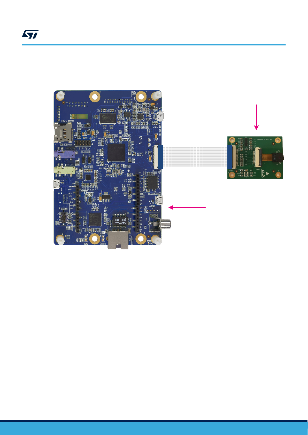
UM2611
Hardware setup
The STM32F4DIS-CAM camera daughterboard is connected to the STM32H747I-DISCO Discovery board
through a flex cable provided with the camera daughterboard as illustrated in Figure 14.
Figure 14. Hardware setup with STM32H747I-DISCO and STM32F4DIS-CAM
STM32F4DIS-CAM
Flex cable
STM32H747I-DISCO
UM2611 - Rev 3
page 44/50
Page 45

4 Testing the CNN
4.1 Testing conditions
The typical testing environment consists of a tablet device placed in front of the camera. In that case, the user
must keep in mind that the following parameters impact the accuracy of the recognition:
• Ambiance light and illumination, for instance neon light flickering
• Quality of the input image displayed by the tablet. High-resolution is required
• Distance between the camera and the tablet
• Reflection, for instance when a tablet is used as input image source
Adjusting the camera contrast by pressing the joystick [LEFT] ans [RIGHT] buttons is a way to improve the
accuracy of the recognition.
4.2 Camera and LCD setting adjustments
The LCD brightness is set using the joystick ([UP] and [DOWN]).
The camera contrast levels are adjusted using the joystick ([LEFT] and [RIGHT]).
The LCD brightness and camera contrast levels are set to their default values using the joystick ([SEL]).
UM2611
Testing the CNN
UM2611 - Rev 3
page 45/50
Page 46

Revision history
Table 16. Document revision history
Date Version Changes
17-Jul-2019 1 Initial release.
Replaced former section Test mode with Section 3.2.8 Embedded validation
and testing.
Replaced former section Two acquisition modes with Section 3.2.7 Two
visualization modes.
24-Dec-2019 2
10-Sep-2020 3
Added Section 3.2.3 Training script.
Updated the folder tree across the entire document.
Updated the entire document with respect to the possible buffer optimization
offered by the allocate input in activation option in STM32Cube.AI.
Updated measurement conditions and results in Section 3.2.5 Execution
performance and overall memory footprint.
Document entirely updated:
• Added person presence detection applications
• Updated data buffer and memory usage
• Updated performance measurements and memory footprints
• Updated folder organization and content
• Updated scenarios
• Updated validation, capture and testing modes
UM2611
UM2611 - Rev 3
page 46/50
Page 47

UM2611
Contents
Contents
1 General information ...............................................................2
1.1 FP-AI-VISION1 function pack feature overview .....................................2
1.2 Software architecture ...........................................................3
1.3 Terms and definitions ...........................................................3
1.4 Overview of available documents and references....................................4
2 Building a CNN-based computer vision application on STM32H7 ...................5
2.1 Integration of the generated code .................................................6
3 Package content...................................................................8
3.1 CNN model ...................................................................8
3.1.1 Food recognition application ................................................8
3.1.2 Person presence detection application ........................................8
3.2 Software ......................................................................9
3.2.1 Folder organization .......................................................9
3.2.2 Quantization process ....................................................14
3.2.3 Training scripts .........................................................14
3.2.4 Memory requirements ....................................................15
3.2.5 Execution performance ...................................................29
3.2.6 Memory footprint........................................................34
3.2.7 Visualization modes .....................................................35
3.2.8 Embedded validation, capture and testing.....................................35
3.2.9 Output display..........................................................42
3.3 Hardware setup...............................................................43
4 Testing the CNN ..................................................................45
4.1 Testing conditions .............................................................45
4.2 Camera and LCD setting adjustments ............................................45
Revision history .......................................................................46
Contents ..............................................................................47
List of tables ..........................................................................48
List of figures..........................................................................49
UM2611 - Rev 3
page 47/50
Page 48

UM2611
List of tables
List of tables
Table 1. List of acronyms ....................................................................3
Table 2. References ........................................................................4
Table 3. SRAM memory buffers for food recognition applications ........................................ 18
Table 4. SRAM memory buffers for person presence detection applications................................. 19
Table 5. STM32H747XIH6 SRAM memory map ....................................................20
Table 6. Compile flags ..................................................................... 26
Table 7. Summary of IAR Embedded Workbench® project configurations versus memory schemes ................ 28
Table 8. Measurements of frame capture and preprocessing times for the food recognition application examples ....... 29
Table 9. Measurements of frame capture and preprocessing times for the person presence detection application examples29
Table 10. Configurations supported by the FP-AI-VISION1 function pack for the food recognition applications .......... 30
Table 11. Configurations supported by the FP-AI-VISION1 function pack for the person presence detection applications .. 30
Table 12. Execution performance of the food recognition application ...................................... 31
Table 13. Execution performance of the optimized food recognition application ............................... 32
Table 14. Execution performance of the person presence detection application ............................... 33
Table 15. Memory footprints per application........................................................ 34
Table 16. Document revision history ............................................................. 46
UM2611 - Rev 3
page 48/50
Page 49

UM2611
List of figures
List of figures
Figure 1. FP-AI-VISION1 architecture ...........................................................3
Figure 2. CNN-based computer vision application build flow............................................5
Figure 3. FP-AI-VISION1 folder tree ............................................................9
Figure 4. Data buffers during execution flow...................................................... 16
Figure 5. SRAM allocation - Memory optimized scheme ............................................. 22
Figure 6. SRAM allocation - FPS optimized scheme ................................................ 23
Figure 7. Flash programming (1 of 2) .......................................................... 25
Figure 8. Flash programming (2 of 2) .......................................................... 26
Figure 9. Validation, capture and testing menu .................................................... 36
Figure 10. Overview of validation, capture and testing modes .......................................... 37
Figure 11. Onboard Validation summary of information for a food recognition example ......................... 41
Figure 12. Onboard Validation classification report for a food recognition example ............................ 42
Figure 13. Food recognition example with green LED on.............................................. 43
Figure 14. Hardware setup with STM32H747I-DISCO and STM32F4DIS-CAM .............................. 44
UM2611 - Rev 3
page 49/50
Page 50

UM2611
IMPORTANT NOTICE – PLEASE READ CAREFULLY
STMicroelectronics NV and its subsidiaries (“ST”) reserve the right to make changes, corrections, enhancements, modifications, and improvements to ST
products and/or to this document at any time without notice. Purchasers should obtain the latest relevant information on ST products before placing orders. ST
products are sold pursuant to ST’s terms and conditions of sale in place at the time of order acknowledgement.
Purchasers are solely responsible for the choice, selection, and use of ST products and ST assumes no liability for application assistance or the design of
Purchasers’ products.
No license, express or implied, to any intellectual property right is granted by ST herein.
Resale of ST products with provisions different from the information set forth herein shall void any warranty granted by ST for such product.
ST and the ST logo are trademarks of ST. For additional information about ST trademarks, please refer to www.st.com/trademarks. All other product or service
names are the property of their respective owners.
Information in this document supersedes and replaces information previously supplied in any prior versions of this document.
© 2020 STMicroelectronics – All rights reserved
UM2611 - Rev 3
page 50/50
 Loading...