

Page 1
UM2043
User manual
Getting started with the STM32Cube function pack for IoT sensor node with
telemetry and device management applications for Microsoft Azure cloud
Introduction
FP-CLD-AZURE1 is an STM32Cube function pack which lets you safely connect a B-L475E-IOT01A or STEV
node to Microsoft Azure IoT, transmit sensor data and receive commands from Azure IoT Central PnP.
It fully supports Azure device management primitives and includes a sample implementation for firmware update over the air
(FOTA).
The package also contains a sample application for data telemetry/device management and firmware update to be connected to
Azure IoT Central PnP application.
This software, together with the suggested combination of STM32 and ST devices, can be used, for example, to develop
sensor-to-cloud applications for a broad range of use cases, such as smart home or smart industry.
The software runs on the STM32 microcontroller and includes drivers for the Wi-Fi connectivity, and motion and environmental
sensors.
AL-STWINKT1B
RELATED LINKS
Visit the STM32Cube ecosystem web page on www.st.com for further information
UM2043 - Rev 9 - March 2021
For further information contact your local STMicroelectronics sales of
fice.
www.st.com
Page 2

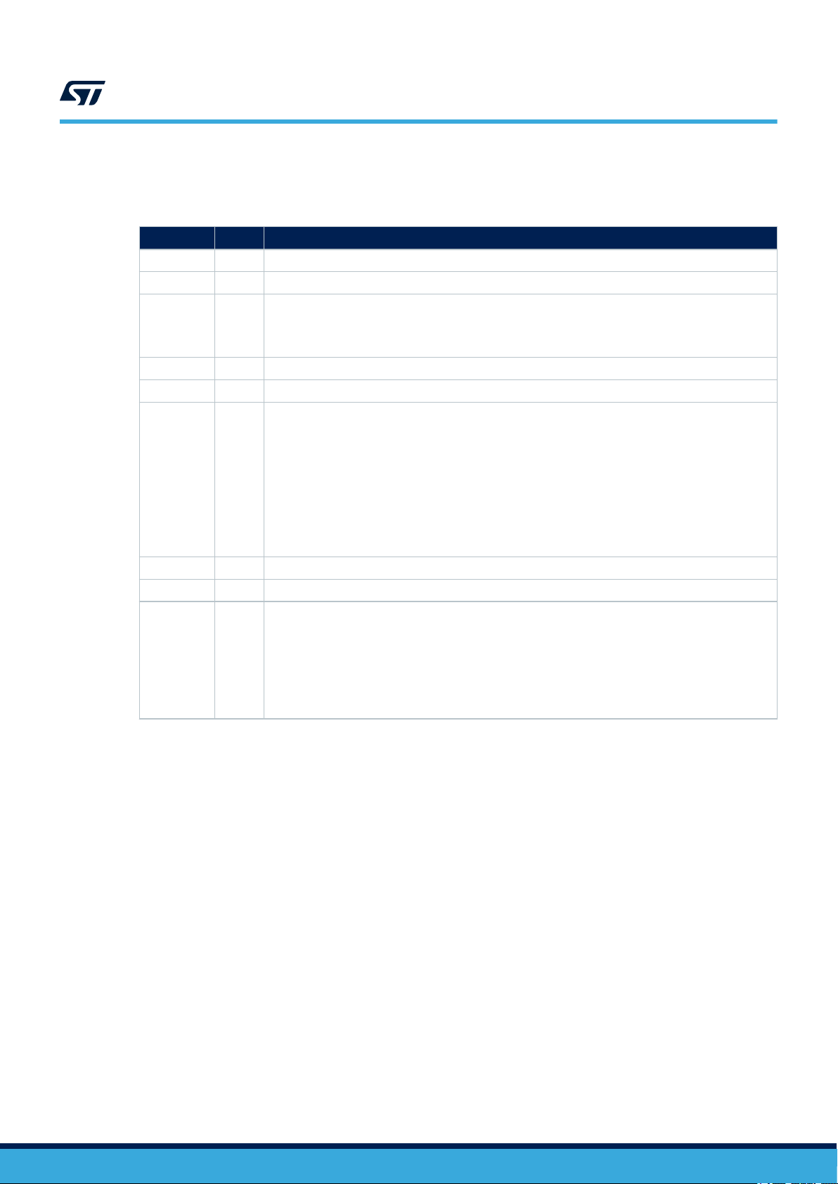
1 Acronyms and abbreviations
Table 1. List of acronyms
Acronym Description
AP Access point
BSP Base support package
FOTA Firmware update over-the-air
DICE Device identifier composition engine
DPS Device provisioning system
GPIO General purpose input/output
HAL Hardware abstraction layer
HTML Hypertext markup language
HTTP Hypertext transfer protocol
IDE Integrated development environment
IoT Internet of things
I²C Inter-integrated circuit
MCU Microcontroller unit
MEMS Micro electro-mechanical systems
ODE Open development environment
UM2043
Acronyms and abbreviations
PnP IoT Central Plug and Play
REST API Representational state tranfer apis
RIoT Robust Intenet of Things
SDK Software development kit
SMD Surface mount device
SSID Service set identifier
STM32UID STM32 unique device ID
UART Universal asynchronous receiver/transmitter
URL Uniform resource locator
Wi-Fi Wireless LAN based on IEEE 802.11
WLAN Wireless local area network
UM2043 - Rev 9
page 2/25
Page 3
2 FP-CLD-AZURE1 software description
Applications
STM32Cube Hardware Abstraction Layer (HAL)
Middleware
Hardware
Abstraction
Meta Data Mgr
Hardware
mbedTLS
Network Library
B-L475E-IOT01A
Discovery kit IoT node
Azure IoT SDK Public Review
STEVAL-STWINKT1B
evaluation board
Azure1 PNP
BootLoader
2.1 Overview
The package features:
•
Complete firmware to safely connect a node with sensors to Microsoft Azure IoT using Wi-Fi communication
technology
• A sample application for data telemetry/device management to be connected to Azure IoT Central PnP
application
• Middleware libraries featuring Microsoft Azure IoT software development, transport-level security (mbedTLS)
and meta-data management
• Ready-to-use binaries to connect the node to Azure IoT Central PnP application for sensor data visualization
and device management (FOTA)
• Sample implementations available for STM32L4 Discovery Kit for IoT node (B-L475E-IOT01A) and for
STWIN SensorTile Wireless Industrial Node development kit (STEVAL-STWINKT1B)
• Easy portability across different MCU families, thanks to STM32Cube
• Free, user-friendly license terms
UM2043
FP-CLD-AZURE1 software description
2.2 Architecture
The software layers used by the application to access and use the STM32 microcontroller and the Wi-Fi and
sensors are:
• STM32Cube HAL driver layer: a simple, generic, multi-instance set of APIs (application programming
interfaces) to interact with the upper layer applications, libraries and stacks. The APIs are based on a
common framework so that overlying software like middleware can implement functions and routines without
specific microcontroller unit (MCU) hardware configurations. This structure improves library code reusability
and guarantees easy portability across other devices.
• Board support package (BSP) layer: drives the STM32 Nucleo board peripherals like the LED, user
button, etc. (not the MCU), with a specific set of APIs. This interface also helps in identifying the specific
board version.
• Middleware layer: contains the MetaDataManager to save Meta Data in the STM32 Flash memory
mbedTLS and the Microsoft Azure IoT device SDK (https://github.com/Azure/azure-iot-sdks) to facilitate the
connection of STM32 Nucleo with Azure IoT services.
,
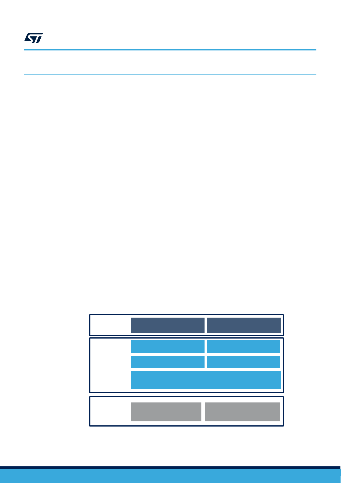
Figure 1. FP-CLD-AZURE1 software architecture
UM2043 - Rev 9
page 3/25
Page 4
2.3 Folder structure
UM2043
Folder structure
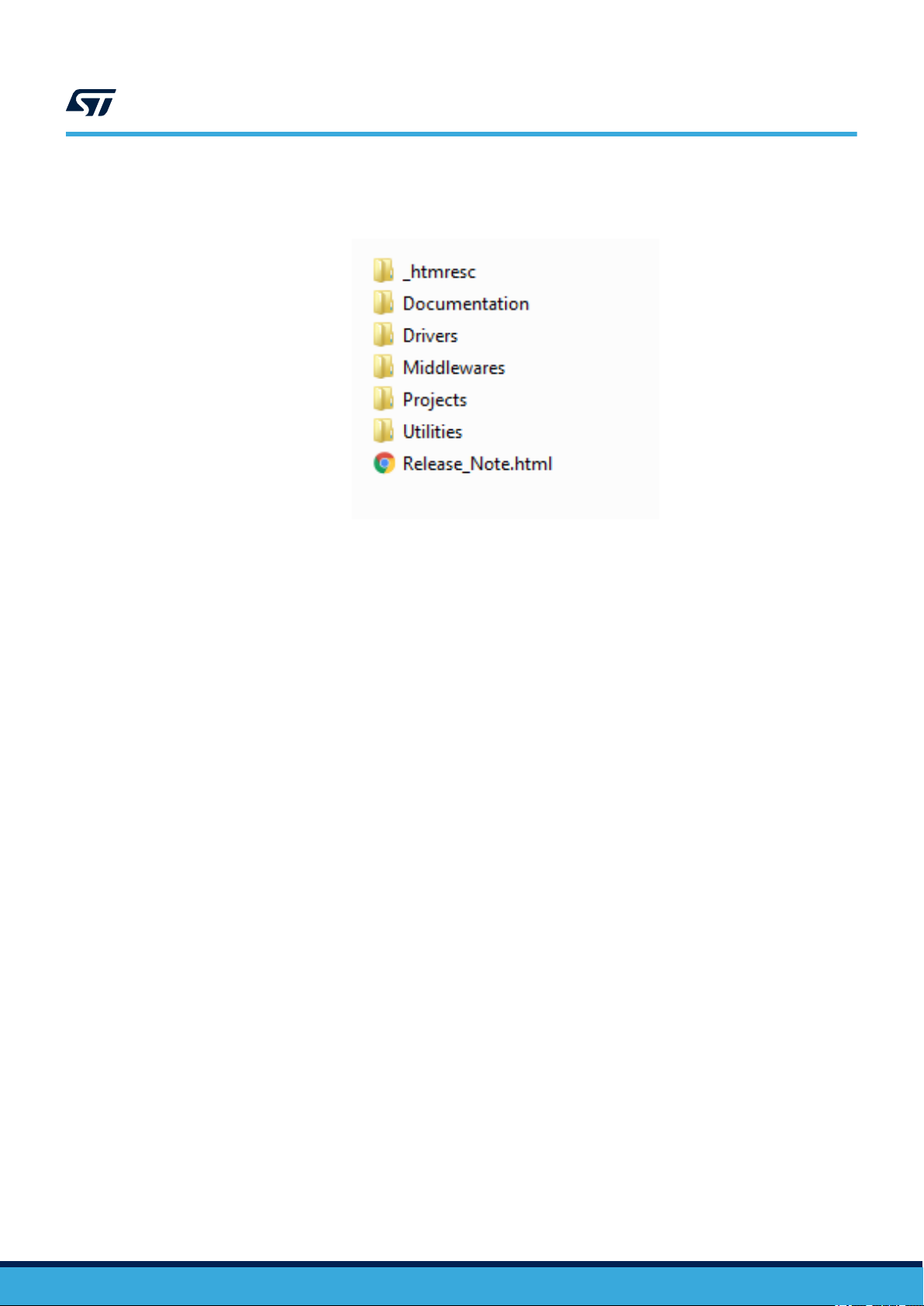
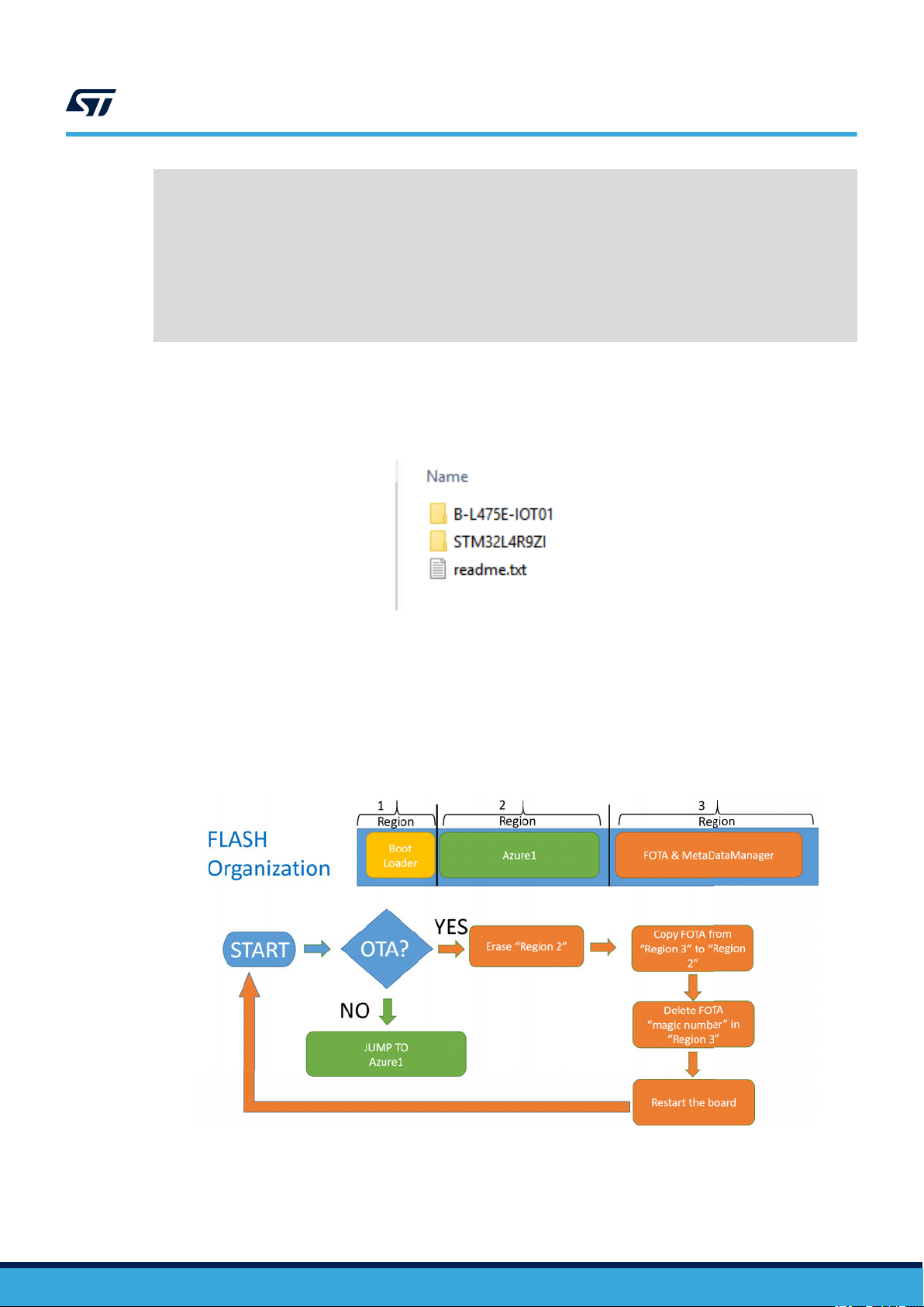
Figure 2. Package folder structure
The following folders are included in the software package:
• Documentation: with two compiled HTML files generated from the source code detailing the software
components and APIs (one for each project).
• Drivers: the HAL drivers and the board-specific drivers for each supported board or hardware platform,
including those for the on-board components, and the CMSIS vendor-independent hardware abstraction
layer for the ARM Cortex-M processor series.
• Middlewares: the middleware interface for MetaDataManager, mbedTLS and the porting of Microsoft Azure
IoT device SDK.
• Utilities: contains BootLoader for B-L475E-IOT01A and for STEVAL-STWINKT1.
• Projects contains:
– the AzurePnP sample application (for B-L475E-IOT01A/STEVAL-STWINKT1B) to transmit sensor data
and receive commands via a personal Azure account using IoT Central PnP accessible through the
link in the documentation included in the source package that allows importing the application template
used for this example
– the BootLoader project used in FP-CLD-AZURE1 for the firmware update procedure
– sample applications that can be compiled with IAR Embedded Workbench for ARM, RealView
Microcontroller Development Kit (MDK-ARM-STM32) or STM32CubeIDE development environments
– for each sample application, a configurable pre-compiled binary to connect devices to the Azure web
dashboards
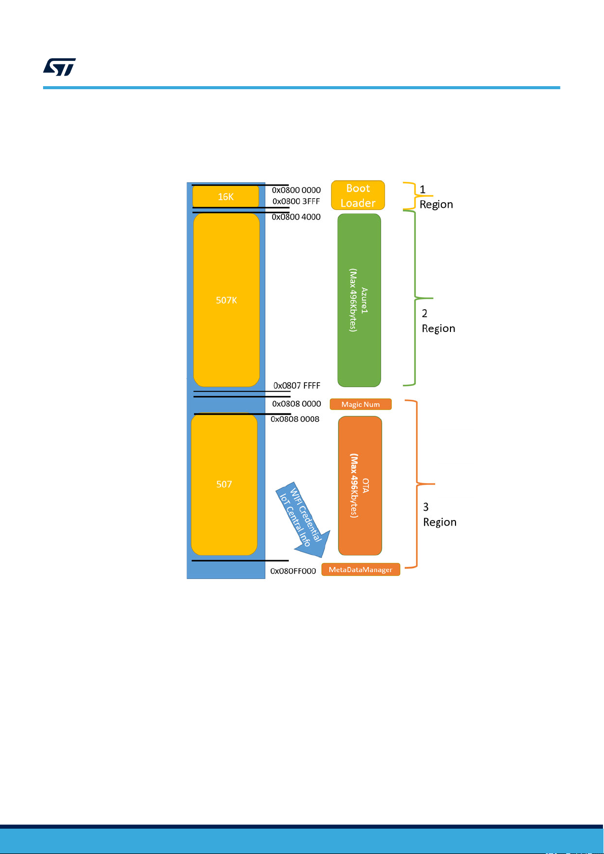
2.4 Flash memory management
The sample application uses the Flash memory to:
1. save the Wi-Fi credentials and the IoT Central PnP information in the Meta Data Manager;
2. allow the Firmware-Over-The-Air update
To enable these features the Flash is divided in different regions (see Figure 3. Azure1 Flash structure for
STM32L475VG):
1. the first region contains a custom boot loader (required for firmware update);
2. the second region contains the application firmware;
3. the third region is used in a firmware update procedure to store the new downloaded firmware before
updating it, and to save data inside the Meta Data Manager.
The STEVAL-STWINKT1B embeds the STM32L4R9ZI microcontroller with 2 MBytes of Flash divided in pages
of 4 KBytes. The B-L475E-IOT01A embeds the STM32L475VG microcontroller with 1 MByte of Flash divided in
pages of 2 KBytes. In this section the STM32L475VG is used as example, even if the STM32L4R9ZI has a similar
Flash organization.
UM2043 - Rev 9
page 4/25
Page 5
UM2043
The boot process for the firmware update over-the-air (FOTA) application
The Meta Data Manager is placed at the end of the Flash (0x080FF000 for STM32L475VG). For more information
®
on the Flash memory management, refer to RM0351: "STM32L4x5 and STM32L4x6 advanced Arm
-based 32-bit
MCUs" on www.st.com.
Figure 3. Azure1 Flash structure for STM32L475VG
2.5 The boot process for the firmware update over-the-air (FOTA) application
To enable the firmware update procedure, the Azure1 application binary cannot be flashed at the beginning of the
Flash memory (address 0x08000000), and is therefore compiled to run from the beginning of the second Flash
region (at 0x08004000).
To enable this procedure, a vector table offset is set in Src/system_stm32l4xx.c (for B-L475E-IOT01A or STEVAL-
STWINKT1): #define VECT_TAB_OFFSET 0x4000.
The linker script also requires changes; in this section, considering the B-L475E-IOT01A as example, the Linker
script for Azure, compiled using IAR Embedded Workbench for ARM, is modified as follows:
UM2043 - Rev 9
page 5/25
Page 6
UM2043
The installation process for the firmware update over-the-air (FOTA) application
/*-Specials-*/
define symbol __ICFEDIT_intvec_start__ = 0x08004000;
/*-Memory Regions-*/
define symbol __ICFEDIT_region_ROM_start__ = 0x08004000;
define symbol __ICFEDIT_region_ROM_end__ = 0x0807FFFF;
define symbol __ICFEDIT_region_RAM_start__ = 0x20000000;
define symbol __ICFEDIT_region_RAM_end__ = 0x20017FFF;
define symbol __ICFEDIT_region_SRAM2_start__ = 0x10000000;
define symbol __ICFEDIT_region_SRAM2_end__ = 0x10007FFF;
/*-Sizes-*/ define symbol __ICFEDIT_size_cstack__ = 0x6000;
define symbol __ICFEDIT_size_heap__ = 0x12000;
Using the above linker script, the maximum usable code size is fixed at 496 KB.
Before flashing the compiled Azure1 firmware, you must flash the appropriate bootloader binary for B-L475E-
IOT01A, available in the Utilities\BootLoader folder, in the first Flash region (address 0x08000000).
Figure 4. BootLoader folder content
When the firmware update procedure is activated, the new firmware is downloaded and copied in the third Flash
region.
After board reset, the following procedure applies:
• if there is a new firmware downloaded in the third Flash region, the BootLoader overwrites the second Flash
region (containing the current firmware), replaces its content with the new firmware and restarts the board;
• if there is no new firmware downloaded, the BootLoader jumps to the firmware stored in region 2.
Figure 5. Azure1 boot sequence
2.6 The installation process for the firmware update over-the-air (FOTA) application
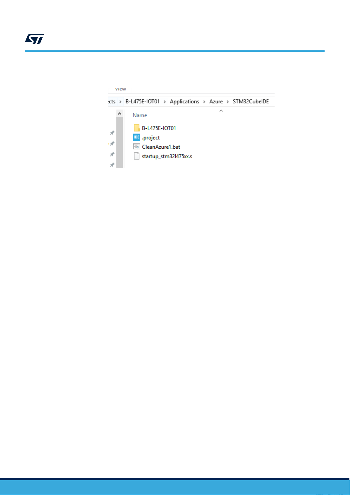
The flashing procedure is simplified by a script available for each IDE (IAR/RealView/STM32CubeIDE).
UM2043 - Rev 9
page 6/25
Page 7
The installation process for the firmware update over-the-air (FOTA) application
The script uses the command line of STM32CubeProgrammer.
Figure 6. Project folder content example
In particular, the script:
• erases the full Flash;
• flashes the BootLoader at the correct position (0x08000000);
• flashes the Azure1 firmware at the correct position (0x08004000).
UM2043
UM2043 - Rev 9
page 7/25
Page 8
UM2043
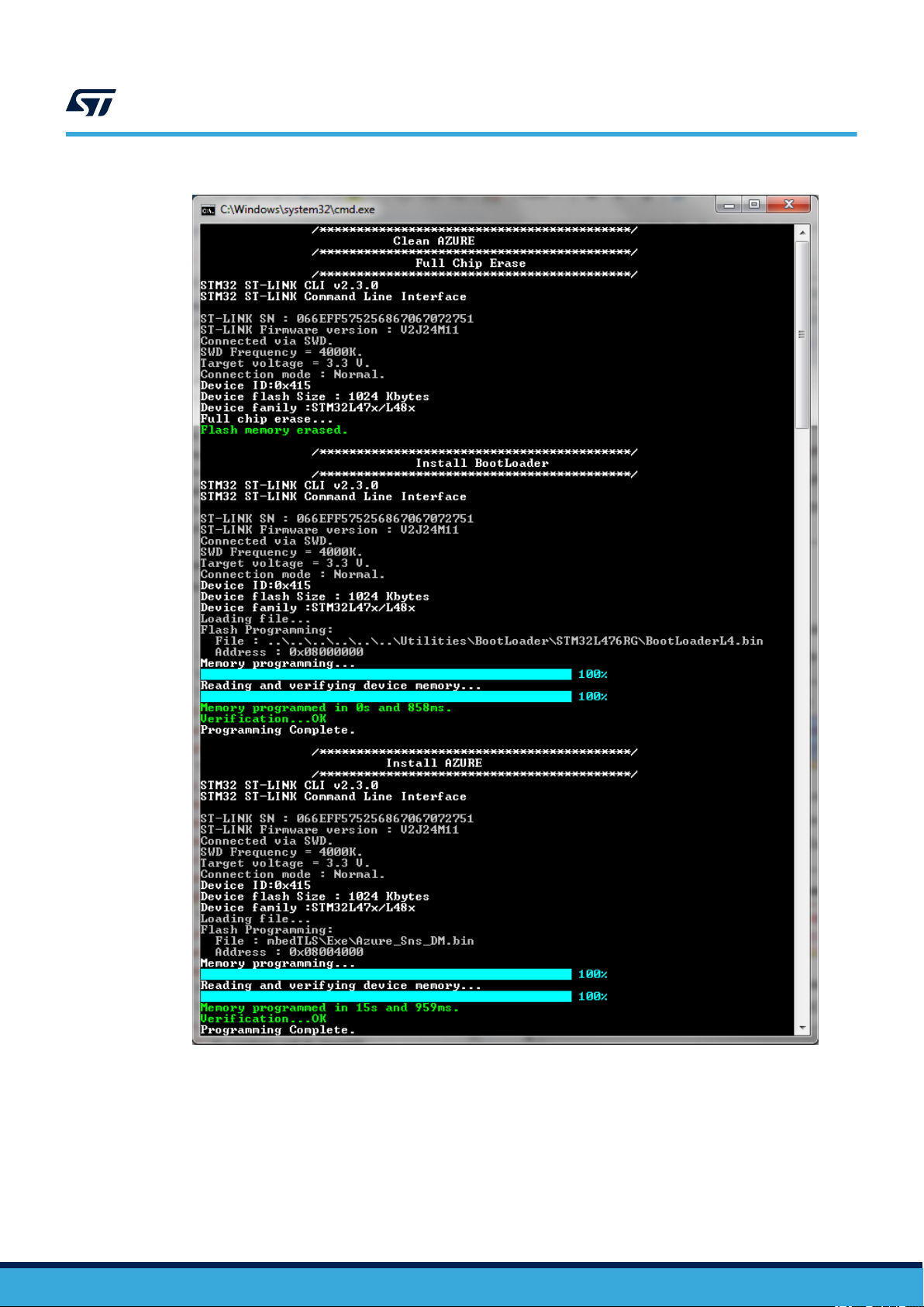
The installation process for the firmware update over-the-air (FOTA) application
Figure 7. BootLoader and Azure installation
UM2043 - Rev 9
The same script also dumps a unique image file (containing the BootLoader and the Azure firmware) that can be
directly flashed to the beginning of the Flash memory.
page 8/25
Page 9

Azure IoT sample application description
Figure 8. BootLoader and Azure Dump process
UM2043
2.7 Azure IoT sample application description
AzurePnP sample application for B-L475E-IOT01A and STEVAL-STWINKT1B is provided in the Projects
directory.
The board uses a Wi-Fi module (which is integrated in the B-L475E-IOT01A but not in the STEVAL-STWINKT1B,
so in the latter case an additional STEVAL-STWINWFV1 Wi-Fi adpater module is needed) and the sample
application reads data values from the temperature, humidity, accelerometer and gyroscope sensors and
transmits them to the Microsoft Azure IoT Hub via Wi-Fi.
The sample application also fully supports Azure device management primitives to remotely control the device,
and includes a sample to trigger firmware update over-the-air procedure.
RELATED LINKS
For further information on how to register a free sample account in Azure connect to Microsoft Azure website
2.7.1 Launch sample application
Once you have set up your system as per Section 3.3 Hardware and software setup, you can proceed to launch
the sample application provided with FP-CLD-AZURE1.
Pre-compiled binaries are available, together with the project files to rebuild the solution.
A serial terminal interface is necessary to monitor the log of the sample application and can be used for device
configuration.
UM2043 - Rev 9
page 9/25
Page 10

2.7.1.1 Serial terminal interface setup
Set up a serial terminal (i.e. TeraTerm) with the parameters reported in the figure below. In particular, set the
proper baudrate (115200) and a Transmit delay (10 msec/char).
UM2043
Azure IoT sample application description
Figure 9. Serial port configuration
2.7.2 Device configuration
It is possible to configure the sample application via serial terminal interface or by modifying the source code to
add Wi-Fi access point credentials: SSID, password and security (WEP,WPA,WPA2).
After configuration, parameters are permanently stored in the Flash memory and can be re-used or changed after
board reset.
2.7.2.1 Wi-Fi access point configuration via serial terminal
Step 1. Open the serial terminal and press Reset.
The very first time the board is flashed and the application is launched, the default SSID and password
are used as written in the code.
Step 2. Press the blue User Button within 3 seconds.
UM2043 - Rev 9
page 10/25
Page 11

Step 3. Enter the requested parameters.
Wi-Fi credentials inserted are stored in the Flash memory and used after each board reset, unless the
User Button is pressed.
UM2043
Azure IoT sample application description
Figure 10. Configure Wi-Fi credentials
2.7.2.2 Configuration in source code
Wi-Fi configuration and Azure IoT Hub connection string can be directly entered in the source code before
recompiling the solution file, as described below.
Step 1. Open the solution file according to the selected IDE and platform used.
Step 2. Open the file azure_config.h and add a custom value for AZURE_DEFAULT_SSID,
AZURE_DEFAULT_SECKEY, AZURE_DEFAULT_PRIV_MODE.
Step 3. Rebuild the solution file according to the selected IDE and flash the microcontroller.
Follow the procedure described in Section 2.6 The installation process for the firmware update
over-the-air (FOTA) application.
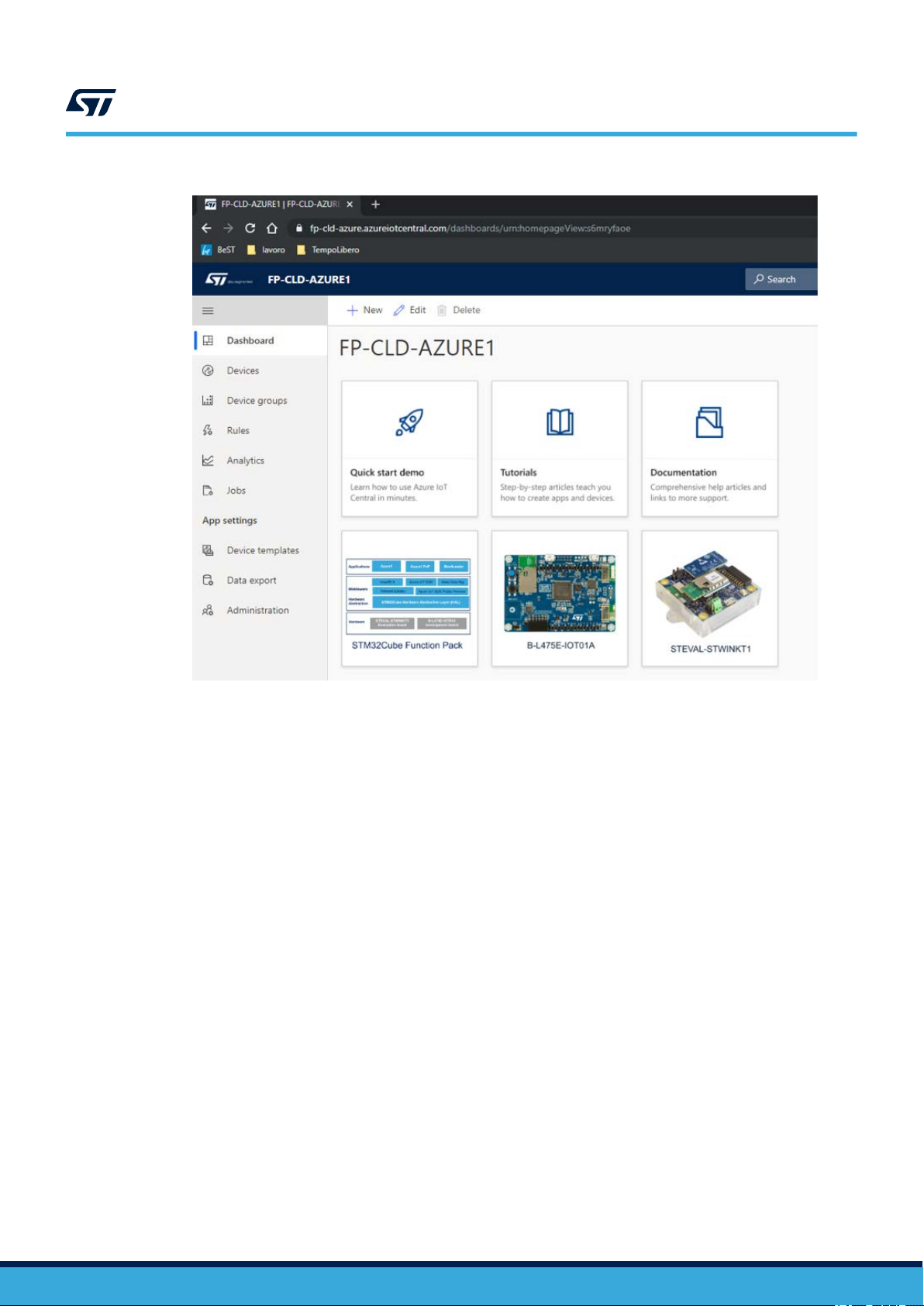
2.7.3 IoT Central PnP sample for Azure application
For B-L475E-IOT01A/STEVAL-STWINKT1B, the AzurePnP application can send sensor data, receive commands
and make a Firmware-Over-the-Air Update (FOTA) with a private subscription to Microsoft SaaS (software-as-aservice) IoT Central PnP.
The AzurePnP application uses a device application template. To use the same application template inside a
personal account on Microsoft IoT Central, it is necessary to copy the link contained in the FP-CLD-AZURE1
documentation.
UM2043 - Rev 9
page 11/25
Page 12

Azure IoT sample application description
Figure 11. Azure IoT Central PnP: create a new application
UM2043
Choose the application name and the "Pricing Plan".
UM2043 - Rev 9
page 12/25
Page 13
Azure IoT sample application description
Figure 12. Azure IoT Central PnP: Application created
UM2043
Create a real device using the [Devices] tab. Select the Right "Device template" for the board that you are using
and Select "+" for creating a new device.
It is possible to choose another the device name instead of the proposed one.
UM2043 - Rev 9
page 13/25
Page 14

Azure IoT sample application description
Figure 13. Azure IoT Central: real device creation
UM2043
Selecting the created real device, you can view the connection parameters. To find them, select [Connect] inside
the [Device explorer] after having selected the real device created.
Figure 14. Azure IoT Central: retrieve the connection parameters
The connection parameters are:
1. Scope ID: the scope of the DPS instance for the created application. This value is the same for all the real
devices created under the same application.
2. Device ID: the device identification. This value is different for each device created.
3. Primary Key: the primary device SAS token. This value is different for each device created.
UM2043 - Rev 9
page 14/25
Page 15

UM2043
Azure IoT sample application description
After having retrieved these parameters, you can run the pre-compiled binary Azure_PnP_BL.bin on the node
(B-L475E-IOT01A/STEVAL-STWINKT1B). After inserting the Wi-Fi credential access, the board waits for the
connection parameters in the UART console.
Figure 15. Azure IoT Central: connection parameters insertion in the UART console
Note: Parameters are saved in the Flash memory using the MetaData Manager. You can change them anytime by
pressing the [User button] at the boot when the UART asks whether to keep or change the saved values.
Note: With a single device provisioning as shown in the above example, digit y if you already have configured the
Automatic Group Enrollment.
The board contacts the DPS identified by the Scope ID and retrieves the IoT hub and the device name to connect
the application template instantiated. You can view the sensor data sent by the board to the IoT Central.
UM2043 - Rev 9
page 15/25
Page 16

Azure IoT sample application description
Figure 16. Azure IoT Central: sensor data
UM2043
Under [Commands] you can send commands to the board (pause/play/resume/stop/reboot of firmware update)
or set the output data rate or full scale, or enable/disable each board sensor.
UM2043 - Rev 9
page 16/25
Page 17

Azure IoT sample application description
Figure 17. Azure IoT Central: change settings and send commands
UM2043
UM2043 - Rev 9
The [Board Status] tab shows a report for the real device created.
Figure 18. Azure IoT Central: board status
page 17/25
Page 18

3 System setup guide
3.1 Hardware description
3.1.1 STM32L4 Discovery kit for IoT node
The STM32L4 Discovery kit for the IoT node (B-L475E-IOT01A) allows users to develop applications with direct
connection to cloud servers. The STM32L4 Discovery kit enables a wide diversity of applications by exploiting
low-power multilink communication (BLE, Sub-GHz), multiway sensing (detection, environmental awareness) and
ARM® Cortex®-M4 core-based STM32L4 Series features. Arduino™ Uno V3 and PMOD connectivity provide
unlimited expansion capabilities with a large choice of specialized add-on boards.
The STM32L4 Discovery kit includes an ST
STM32Cube software libraries together with packaged software samples for a smooth connection to cloud
servers.
Figure 19. STM32L4 Discovery kit for IoT node
UM2043
System setup guide
-LINK debugger/programmer and comes with the comprehensive
Information regarding the STM32L4 Discovery kit for the IoT node is available at
3.1.2 STEVAL-STWINKT1B wireless industrial node
The STWIN SensorTile wireless industrial node (STEV
design that simplifies prototyping and testing of advanced industrial IoT applications such as condition monitoring
and predictive maintenance.
The kit features a core system board with a range of embedded industrial-grade sensors and an ultra-lowpower microcontroller for vibration analysis of 9-DoF motion sensing data across a wide range of vibration
frequencies, including very high frequency audio and ultrasound spectra, and high precision local temperature
and environmental monitoring.
The development kit is complemented with a rich set of software packages and optimized firmware libraries, as
well as a cloud dashboard application, all provided to help speed up design cycles for end-to-end solutions.
The kit supports BLE wireless connectivity through an on-board module, and Wi-Fi connectivity through a special
plugin expansion board (STEVAL-STWINWFV1). Wired connectivity is also supported via an on-board RS485
transceiver. The core system board also includes an STMod+ connector for compatible, low cost, small form
factor daughter boards associated with the STM32 family, such as the LTE Cell pack.
Apart from the core system board, the kit is provided complete with a 480 mAh Li-Po battery, an STLINK-V3MINI
debugger and a plastic box.
UM2043 - Rev 9
AL-STWINKT1B) is a development kit and reference
page 18/25
Page 19

Figure 20. STEVAL-STWINKT1B SensorTile Wireless Industrial Node
UM2043
Hardware description
The STLINK-V3MINI is a standalone debugging and programming mini probe for STM32 microcontrollers, with
JTAG/SWD interfaces for communication with any STM32 microcontroller located on an application board. It
provides a virtual COM port interface for host PCs to communicate with target MCUs via UART. The STLINK-
V3MINI is supplied with an STDC14 to STDC14 flat cable.
Figure 21. STEVAL-STWINKT1B connected to STLINK-V3MINI
UM2043 - Rev 9
page 19/25
Page 20

3.2 Software requirements
The following software components are needed to set up a suitable development environment for compiling and
running the FP-CLD-AZURE1
• FP-CLD-AZURE1 software available on www.st.com/stm32ode
• Development tool-chain and compiler; the FP-CLD-AZURE1 software supports the three following
environments:
– IAR Embedded Workbench for ARM® (IAR-EWARM) toolchain + ST-LINK
– RealView Microcontroller Development Kit (MDK-ARM-STR) toolchain + ST-LINK
– STM32CubeIDE + ST-LINK
• Serial line monitor (e.g., TeraTerm, https://ttssh2.osdn.jp/)
• STM32CubeProgrammer
package:
3.3 Hardware and software setup
3.3.1 Hardware setup
The following hardware components are needed:
•
For B-L475E-IOT01A:
1. One STM32L4 Discovery Kit for IoT node (order code: B-L475E-IOT01A)
2. One USB type A to Micro-B USB cable to connect the STM32L4 Discovery Kit to the PC
• For the STEVAL-STWINKT1B:
1. One STWIN SensorTile Wireless Industrial Node development kit (order code: STEVAL-STWINKT1B)
2. One Wi-Fi expansion for the SensorTile Wireless Industrial Node (STWIN) kit (order code: STEVAL-
STWINWFV1)
3. Two USB type A to Micro-B USB cables to connect the STWIN Kit and the STLINK-V3MINI to the PC
UM2043
Software requirements
3.3.2 Software setup
3.3.2.1 Development tool-chains and compilers
Select one of the IDEs in Section 3.2 Software requirements and refer to the system and setup information
provided by the selected IDE provider
Project files for all of the supported IDEs can be found inside one of the FP-CLD-AZURE1 package folders, i.e. for
IAR Embedded Workbench for Azure application: Projects\SelectedBoard\Applications\Azure\EWARM.
.
UM2043 - Rev 9
page 20/25
Page 21
Revision history
Date Version Changes
23-Mar-2016 1 Initial release.
29-Apr-2016 2 Minor text edits.
13-Dec-2016 3
06-Jun-2017 4 Updated all content to reflect v3.0 firmware.
19-Oct-2017 5 Updated all content to reflect v3.1 firmware.
07-May-2018 6
09-Jan-2019 7 Updated all content to reflect v4.0 firmware version.
02-Apr-2020 8 Updated all document to reflect v5.0.0 firmware version.
11-Mar-2021 9
UM2043
T
able 2. Document revision history
Updated for v2.0 firmware.
Added companion web application information.
Added X-NUCLEO-IKS01A2 support information.
To reflect v3.3 firmware:
•
updated Introduction, Section 2.1 Overview, Section 2.3 Folder structure, Section 2.7 Azure
IoT sample application description, Section 2.7.2.2 Use pre-compiled binaries, Section 2.7.2.3
Modify and rebuild solution files, Section 2.8.3.1 Overview of the web page sections, Section
3.3.1 Hardware setup and Section 3.3.3 System setup guide for STM32 Nucleo and expansion
boards;
• added Section 2.7.7 Motor control sample application, Section 2.7.8 IoT Central sample for
Azure_Sns_DM application, Section 3.1.5 X-NUCLEO-IHM02A1 expansion board and Section
3.1.6 X-NUCLEO-NFC04A1 expansion board;
• removed references to X-NUCLEO-IKS01A1 and X-NUCLEO-NFC01A1 expansion boards.
Updated Introduction, Section 2.1 Overview, Figure 1. FP-CLD-AZURE1 software architecture,
Section 2.3 Folder structure, Section 2.7 Azure IoT sample application description and
Section 3.2 Software requirements.
Removed Section 2.7.1.2 Use pre-compiled binaries, Section 2.7.4 DICE emulator for robust Internet
of Things, Section 2.8 STM32 ODE web dashboard for FP-CLD-AZURE1.
Replaced Section 3.1.2 STEV
STWINKT1B wireless industrial node.
AL-STWINKT1 development kit by Section 3.1.2 STEVAL-
UM2043 - Rev 9
page 21/25
Page 22

UM2043
Contents
Contents
1 Acronyms and abbreviations ......................................................2
2 FP-CLD-AZURE1 software description .............................................3
2.1 Overview .....................................................................3
2.2 Architecture ...................................................................3
2.3 Folder structure ................................................................4
2.4 Flash memory management .....................................................4
2.5 The boot process for the firmware update over-the-air (FOT
A) application ...............5
2.6 The installation process for the firmware update over-the-air (FOTA) application .........6
2.7 Azure IoT sample application description...........................................9
2.7.1 Launch sample application .................................................9
2.7.2 Device configuration .....................................................10
2.7.3 IoT Central PnP sample for Azure application ..................................11
3 System setup guide...............................................................18
3.1 Hardware description ..........................................................18
3.1.1 STM32L4 Discovery kit for IoT node .........................................18
3.1.2 STEVAL-STWINKT1B wireless industrial node .................................18
3.2 Software requirements .........................................................20
3.3 Hardware and software setup ...................................................20
3.3.1 Hardware setup.........................................................20
3.3.2 Software setup .........................................................20
Revision history .......................................................................21
UM2043 - Rev 9
page 22/25
Page 23

UM2043
List of figures
List of figures
Figure 1. FP-CLD-AZURE1 software architecture ...................................................3
Figure 2. Package folder structure .............................................................4
Figure 3. Azure1 Flash structure for STM32L475VG .................................................5
Figure 4. BootLoader folder content ............................................................6
Figure 5. Azure1 boot sequence ...............................................................6
Figure 6. Project folder content example .........................................................7
Figure 7. BootLoader and Azure installation .......................................................8
Figure 8. BootLoader and Azure Dump process ....................................................9
Figure 9. Serial port configuration ............................................................. 10
Figure 10. Configure Wi-Fi credentials .......................................................... 1
Figure 11. Azure IoT Central PnP: create a new application............................................12
Figure 12. Azure IoT Central PnP: Application created ............................................... 13
Figure 13. Azure IoT Central: real device creation .................................................. 14
Figure 14. Azure IoT Central: retrieve the connection parameters........................................14
Figure 15. Azure IoT Central: connection parameters insertion in the UART console........................... 15
Figure 16. Azure IoT Central: sensor data ........................................................16
Figure 17. Azure IoT Central: change settings and send commands ......................................17
Figure 18. Azure IoT Central: board status .......................................................17
Figure 19. STM32L4 Discovery kit for IoT node .................................................... 18
Figure 20. STEVAL-STWINKT1B SensorTile Wireless Industrial Node .................................... 19
Figure 21. STEVAL-STWINKT1B connected to STLINK-V3MINI.........................................19
1
UM2043 - Rev 9
page 23/25
Page 24

UM2043
List of tables
List of tables
T
able 1. List of acronyms ....................................................................2
Table 2. Document revision history .............................................................21
UM2043 - Rev 9
page 24/25
Page 25

UM2043
IMPORTANT NOTICE – PLEASE READ CAREFULLY
STMicroelectronics NV and its subsidiaries (“ST”) reserve the right to make changes, corrections, enhancements, modifications, and improvements to ST
products and/or to this document at any time without notice. Purchasers should obtain the latest relevant information on ST products before placing orders. ST
products are sold pursuant to ST’
Purchasers are solely responsible for the choice, selection, and use of ST products and ST assumes no liability for application assistance or the design of
Purchasers’ products.
No license, express or implied, to any intellectual property right is granted by ST herein.
Resale of ST products with provisions different from the information set forth herein shall void any warranty granted by ST for such product.
ST and the ST logo are trademarks of ST. For additional information about ST trademarks, please refer to www
names are the property of their respective owners.
Information in this document supersedes and replaces information previously supplied in any prior versions of this document.
s terms and conditions of sale in place at the time of order acknowledgement.
.st.com/trademarks. All other product or service
© 2021 STMicroelectronics – All rights reserved
UM2043 - Rev 9
page 25/25
 Loading...