

AN5224
Application note
STM32 DMAMUX: the DMA request router
Introduction
In order to offload certain data transfer duties from the CPU, STM32 microcontrollers (MCUs) and microprocessors (MPUs)
embed direct memory access (DMA) controllers. The DMA can perform block-oriented data transfer upon a peripheral request
or a software trigger.
Each DMA channel has a software-configurable selection of the peripheral requesting its services. On legacy STM32 products,
the channel request selection is implemented within the DMA controller with a restricted list of peripheral requests for a given
channel. The software application cannot freely map any peripheral request to any channel.
STM32 DMA request routing capabilities are enhanced by a DMA request multiplexer (DMAMUX peripheral). The DMAMUX
adds more flexibility to give full dynamic DMA peripheral request mapping instead of pseudo-dynamic mapping. It offers fully
configurable routing of any DMA request from a given peripheral to any DMA controller and/or controller DMA channel.
This application note explains the various DMAMUX features of the products listed in the table below: how to configure the
DMAMUX as well as giving guidance on the use of the new synchronization and request generation capabilities.
For further information on DMAMUX in STM32 devices, refer to the product reference manuals available on www.st.com.
Table 1. Applicable products
Type Product series
STM32H7 Series
STM32G0 Series
Microcontrollers
Microprocessors STM32MP1 Series
STM32G4 Series
STM32L4+ Series
STM32L5 Series
STM32WB Series
AN5224 - Rev 4 - June 2020
For further information contact your local STMicroelectronics sales office.
www.st.com
1 DMAMUX description
A peripheral indicates a request for DMA transfer by setting its DMA request signal. The DMA request is pending
until it is served by the DMA controller that generates a DMA acknowledge signal, and the corresponding DMA
request signal is de-asserted.
In this document, the set of control signals required for the DMA request/acknowledge protocol is not explicitly
described and it is referred to as peripheral DMA request line.
The DMA request router can be considered as an extension of the DMA controller. It routes the DMA peripheral
requests to the DMA controller itself.
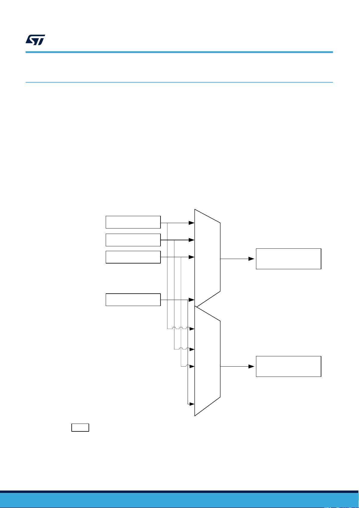
The DMAMUX request multiplexer enables routing a DMA request line from the peripherals to the DMA
controllers of the product. The routing function is ensured by a programmable multi-channel DMA request line
multiplexer. Each channel (DMAMUX channel 0 in the example of the figure below) selects a unique DMA request
line to forward (unconditionally or synchronously) to the associated DMA controller channel (DMA channel 0 in the
example of the figure below). This allows DMA requests to be managed with a high flexibility, maximizing the
number of DMA requests that run concurrently.
AN5224
DMAMUX description
Figure 1. DMAMUX request multiplexer
P1
P2
P3
Pn
...
DMAMUX
channel 0
...
DMAMUX
channel 15
DMA channel 0
DMA channel 15
AN5224 - Rev 4
Px
Peripheral x request (example LPUART1_TX or LPUART1_RX)
page 2/14
2 DMAMUX features
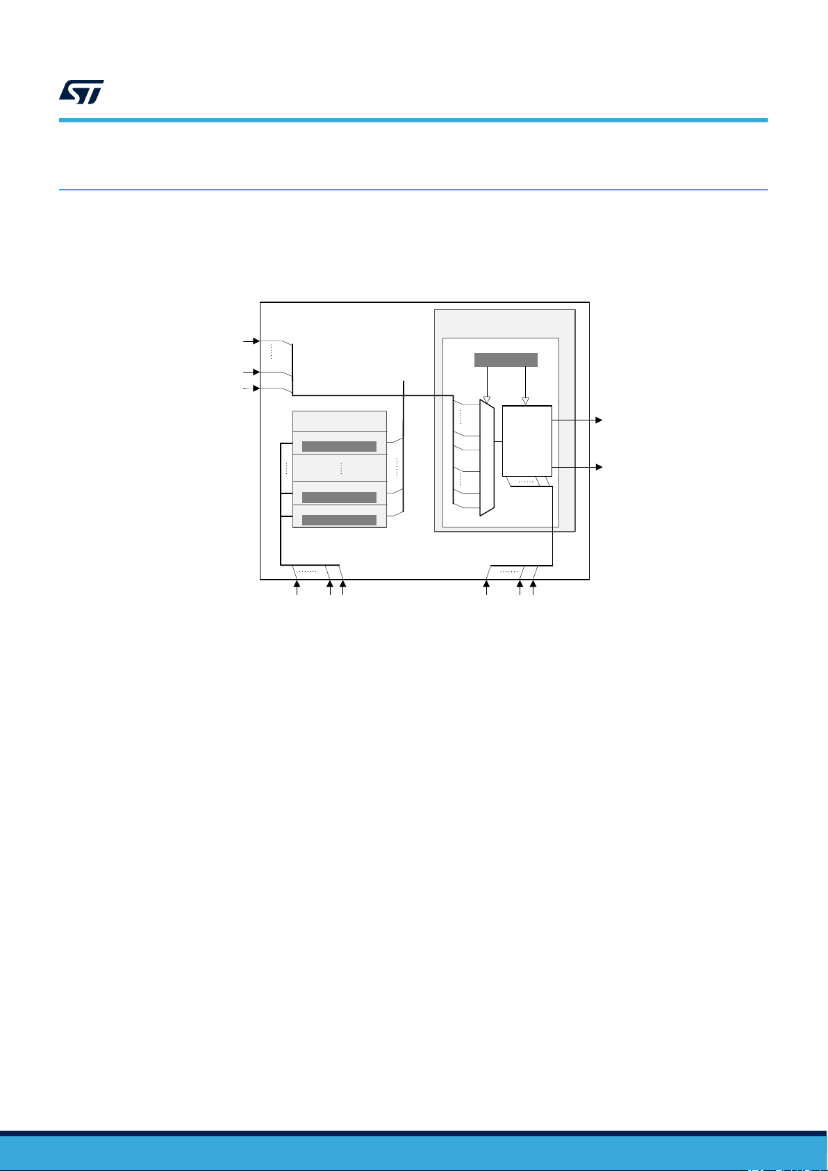
The figure below represents a simplified DMAMUX block diagram. The “Request multiplexer” structure is
duplicated N times depending on the number of DMA channels managed by the DMAMUX.
AN5224
DMAMUX features
Figure 2. DMAMUX simplified block diagram
DMAMUX
p
DMA requests
from peripherals:
dmamux_req_inx
Note: Simplified block diagram with only one request multiplexer.
1
0
Request generator
Channel n
DMAMUX_RGCnCR
Channel 1
DMAMUX_RGC1CR
Channel 0
DMAMUX_RGC0CR
Trigger inputs:
dmamux_trgx
n
1
0
01t
dmamux_req_genx
Request multiplexer
Channel 0
DMAMUX_C0CR
Channel
select
n+p+2
n+3
n+2
n+1
dmamux_reqx
2
1
Synchronization inputs:
Sync
dmamux_syncx
Ctrl
DMA request to DMA Channel 0:
dmamux_req_out0
DMA channel event:
01s
01s
dmamux_evt0
The DMAMUX is mainly composed of two components, the request multiplexer (or router block) and the
request generator.
The request multiplexer includes a synchronization unit per channel, with inputs/outputs as follows:
• Inputs:
– dmamux_reqx: DMA request from a peripheral (dmamux_req_inx) or from the request generator
(dmamux_req_genx)
dmamux_req_gen[0..n] are affected respectively to dmamux_req[1..n+1] and dmamux_req_inx are
affected starting from dmamux_req[n+2].
– dmamux_syncx: optional synchronization event
• Outputs:
– dmamux_req_outx: DMA request dmamux_reqx forwarded from the input to the output
– dmamux_evtx: optional generated event that may be used to trigger/synchronize other DMAMUX
channels
The request generator allows DMA request generation on interrupt signals or events, with input/output as follows:
• Input: dmamux_trgx, trigger event inputs to the request generator sub-block
• Output: dmamux_req_genx, DMA request from the request generator sub-block to the DMAMUX request
multiplexer channels
The number of request multiplexer blocks depends on the number of DMA channels managed by the DMAMUX.
For examples:
• For a 8 channels DMA, 8 request multiplexer channels must be available.
• For a product with two DMA controllers with 8 channels each, 16 request multiplexer channels must be
available.
AN5224 - Rev 4
page 3/14
The request generator is instantiated once by DMAMUX. It contains N channels (depending on the product)
capable of generating DMA requests. Refer to the 'DMAMUX implementation' section in the product reference
manual for more details.
Thanks to the request generator block, user software can trigger DMA transfers based on signals from peripherals
that do not implement the DMA requests.
2.1 Request routing and synchronization
2.1.1 Unconditional request forwarding
In order to perform peripheral-to-memory or memory-to-peripheral transfers, the DMA controller channel requires
each time a peripheral DMA request line. Each time a request occurs, the DMA channel transfers data from/to
peripheral. The DMAMUX request multiplexer channel x allows the selection/routing of the peripheral DMA
request line to the DMA channel x.
When the multiplex is set (DMAREQ_ID not equal to zero), it ensures the actual routing of DMA request line. The
connection of peripheral DMA request to the multiplexer channel output is selected through the programmed ID in
DMAREQ_ID bits of the channel control register (DMAMUX_CxCR).
For each peripheral DMA request line in the product, a unique ID is affected. The value zero
(DMAREQ_ID = 0x00) corresponds to no DMA request line selected.
After the configuration of a DMAMUX channel, the corresponding DMA controller channel can be configured on its
turn. Two different DMAMUX channels can not be configured to select the same peripheral DMA request line as
source.
AN5224
Request routing and synchronization
2.1.2 Conditional request forwarding
In addition to unconditional request forwarding, the synchronization unit allows the software to implement
conditional request forwarding. The routing is effectively done only when a defined condition is detected. The
DMA transfers can be synchronized with internal or external signals.
For example, the user software can use the synchronization unit to initiate or adjust data transmission throughput.
DMA request can be forwarded in one of the following way:
• each time an edge is detected on a GPIO pin (EXTI)
• in response to a periodic event from a timer
• in response to an asynchronous event from a peripheral
• in response to an event from another request router (request chaining)
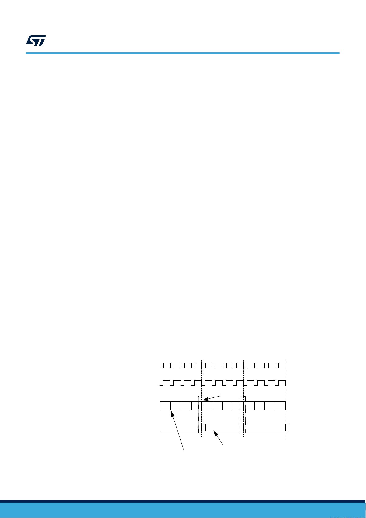
On top of DMA request conditioning, the synchronization unit allows the generation of events that may be used by
other DMAMUX sub-blocks (such as the request generator or another DMAMUX request multiplexer channel).
Figure 3. DMA request line multiplexer channel - Event generation
dmamux_req
dmamux_req_out
DMA request counter
Request counter auto-reload
23 1 0 23 1 0 23 1 0
AN5224 - Rev 4
dmamux_evt
Event generation (can be used as sync event)
Request counter decrements after each transfer.
page 4/14

AN5224
Request routing and synchronization
When DMAMUX channel is configured in synchronous mode its behavior is as follows:
1. The request multiplexer input (DMA request from the peripheral) can become active but it is not forwarded
on the DMAMUX request multiplexer output until the synchronization signal is received.
2. When the sync event is received the request multiplexer connects its input and output and the pending
peripheral request, if any, is forwarded.
3. Each forwarded DMA request decrements the request multiplexer counter (user programmed value). When
the counter reaches zero and the last forwarded request is acknowledged by the DMA controller, the
connection between the DMA controller and the peripheral is disabled (not forwarded) waiting for a new
synchronization event.
For each underrun of the counter, request multiplexer line can generate an optional event to synchronize with a
second DMAMUX line. The same event can be used in some low-power scenarios to switch the system back to
stop mode without any CPU intervention.
Synchronization mode can be used to automatically synchronize data transfers with a timer for example, or to
trigger the transfers on a peripheral event.
The synchronization signal (SYNC_ID), the synchronization signal polarity (SPOL) and the number of requests to
forward (NBREQ+1) are configured in the request line multiplexer channel configuration register
(DMAMUX_CxCR).
AN5224 - Rev 4
page 5/14

2.2 Request generation
The request generator can be considered as an intermediary between a peripheral and the DMA controllers. It
allows peripherals without DMA capability (such as RTC alarm or comparators) to generate a programmable
number of DMA requests on an event. The trigger signal (SIG_ID), the trigger polarity (GPOL) and the number of
requests minus 1 to generate (GNBREQ) are configured in the request generator configuration register
(DMAMUX_RGxCR).
Upon the trigger event reception, the corresponding generator channel starts generating DMA requests on its
output. Each time the DMAMUX generated request is served by the connected DMA controller, a built-in DMA
request counter (one counter per request generator channel) is decremented.
At its underrun, the request generator channel stops generating DMA requests and the DMA request counter is
automatically reloaded to its programmed value upon the next trigger event.
dmamux_req_gen
dmamux_req_out
AN5224
Request generation
Figure 4. DMA request generation
Request counter auto-reload (wait for new trigger)
2.3
Request generator counter
23 1 0 23 1 0 3
dmamux_trg
Active trigger event edge
Generator request counter decremets after each transfer.
If a new trigger event is received while the generator is managing the previous triggered DMA request sequence,
then the request trigger event overrun flag bit OFx is asserted by the hardware in the status DMAMUX_RGSR
register.
Request generation and synchronization
In order to implement autonomous transfer and control scenarios, the DMAMUX offers the possibility to combine
request generation and request synchronization feature within the same configuration.
AN5224 - Rev 4
page 6/14

3 DMAMUX examples
These examples use the STM32CubeMX tool version 4.26.1, running on STM32 microcontrollers (based on
Arm® cores).
Note: Arm is a registered trademark of Arm Limited (or its subsidiaries) in the US and/or elsewhere.
3.1 Example using the synchronization
After the configuration of the DMA channel to serve the peripheral DMA request line (example SPI6_TX),
synchronization block can be enabled as shown in the figure below. In this case, the LPTIM3_out signal rising
edge is used to control the transfer periods.
Figure 5. Example using the synchronization (based on STM32CubeH7)
AN5224
DMAMUX examples
AN5224 - Rev 4
· Set Enable synchronization checkbox
· Set Synchronization signal from the list
(configured in the application)
· Set Synchronization signal polarity
· Set Enable event checkbox
(enable event generation)
· Set number of requests to be forwarded
page 7/14

Example using the DMAMUX request generator sub-block
3.2 Example using the DMAMUX request generator sub-block
In order to have some automation, new DMA transfers can be generated following the DMA transfer to SPI6.
Thanks to the DMAMUX Channel 0 event generation, the request generator can be triggered. The scenario can
be configured as shown in the figure below.
Figure 6. Example using the request generator (based on STM32CubeH7)
· Set request generation signal from the list
(using the event from DMAMUX2 request
generator 0)
· Set signal polarity (using the rising edge)
· Set the number of requests to be generated
(from the DMAMUX2 channel 1 to the BDMA
channel 1)
· The synchronization for this channel is not
enabled.
AN5224
AN5224 - Rev 4
page 8/14

3.3 STM32CubeH7 examples
The following examples are extracted from the STM32CubeH7 ones:
• DMAMUX_RequestGen
This example uses the EXTI0 line to trigger the DMAMUX request generator and to perform DMA data
transfers from the SRAM buffer to the GPIO output data register, changing output pin state on every EXTI0
rising edge occurrence.
DMAMUX2
AN5224
STM32CubeH7 examples
Figure 7. DMAMUX_RequestGen
SRAM4 buffer
BDMA Ch 0
Mux Ch 0
Req Gen ch 0
PF10
GPIOF ODR
EXTI
0
EXTI
PA0
• DMAMUX_SYNC
This example uses the USART1 in DMA synchronized mode to send a countdown from 10 to 00 with 2
seconds period. The DMAMUX synchronization block is configured to synchronize the DMA transfer with the
LPTIM1 output signal. Each rising edge of the synchronization signal (LPTIM1 output signal) authorizes four
USART1 requests to be transmitted to the USART1 peripheral using the DMA. These four requests
represent the two characters '\n\r' plus the two characters count down itself from 10 to 00. LPTIM1 is
configured to generate a PWM with 2 seconds period.
Figure 8. DMAMUX_SYNC
SRAM buffer =
{10 to 00 }
DMAMUX1
NBREQ=4-1
Mux Ch 0
usart1_tx_dma
Synch
DMA Ch 0
TX
10
09
08
USART1
AN5224 - Rev 4
lptim1_out
LPTIM1
out
2 s
page 9/14

4 Conclusion
The DMAMUX controller is designed to simplify embedded application resources allocation as it offers the
flexibility to dynamically allocate a peripheral to a DMA channel. Additionally it increases the DMA capabilities by
offering synchronization mechanism that allows an increased CPU offload from transfer control and
synchronization. Also the combination of synchronization and request generation can be used to implement
power optimized data transfer (in autonomous mode without CPU involvement).
AN5224
Conclusion
AN5224 - Rev 4
page 10/14

Revision history
16-Oct-2018 1 Initial release.
20-Nov-2018 2 Updated Table 1. Applicable products.
16-Jan-2019 3 Updated Section 3. DMAMUX examples.
8-Jun-2020 4
AN5224
Table 2. Document revision history
Date Version Changes
Updated Introduction with new products STM32G4, STM32L5 and STM32MP1
Series.
AN5224 - Rev 4
page 11/14

AN5224
Contents
Contents
1 DMAMUX description ..............................................................2
2 DMAMUX features .................................................................3
2.1 Request routing and synchronization ..............................................4
2.1.1 Unconditional request forwarding ............................................4
2.1.2 Conditional request forwarding ..............................................4
2.2 Request generation.............................................................6
2.3 Request generation and synchronization ...........................................6
3 DMAMUX examples................................................................7
3.1 Example using the synchronization................................................7
3.2 Example using the DMAMUX request generator sub-block............................8
3.3 STM32CubeH7 examples .......................................................9
4 Conclusion .......................................................................10
Revision history .......................................................................11
AN5224 - Rev 4
page 12/14

AN5224
List of figures
List of figures
Figure 1. DMAMUX request multiplexer..........................................................2
Figure 2. DMAMUX simplified block diagram ......................................................3
Figure 3. DMA request line multiplexer channel - Event generation .......................................4
Figure 4. DMA request generation .............................................................6
Figure 5. Example using the synchronization (based on STM32CubeH7)...................................7
Figure 6. Example using the request generator (based on STM32CubeH7) .................................8
Figure 7. DMAMUX_RequestGen .............................................................. 9
Figure 8. DMAMUX_SYNC ..................................................................9
AN5224 - Rev 4
page 13/14

AN5224
IMPORTANT NOTICE – PLEASE READ CAREFULLY
STMicroelectronics NV and its subsidiaries (“ST”) reserve the right to make changes, corrections, enhancements, modifications, and improvements to ST
products and/or to this document at any time without notice. Purchasers should obtain the latest relevant information on ST products before placing orders. ST
products are sold pursuant to ST’s terms and conditions of sale in place at the time of order acknowledgement.
Purchasers are solely responsible for the choice, selection, and use of ST products and ST assumes no liability for application assistance or the design of
Purchasers’ products.
No license, express or implied, to any intellectual property right is granted by ST herein.
Resale of ST products with provisions different from the information set forth herein shall void any warranty granted by ST for such product.
ST and the ST logo are trademarks of ST. For additional information about ST trademarks, please refer to www.st.com/trademarks. All other product or service
names are the property of their respective owners.
Information in this document supersedes and replaces information previously supplied in any prior versions of this document.
© 2020 STMicroelectronics – All rights reserved
AN5224 - Rev 4
page 14/14
 Loading...