

STMicroelectronics UM2800, STEVAL-VOICE-UI User Manual
UM2800
User manual
Getting started with the STEVAL-VOICE-UI voice user interface evaluation kit
Introduction
The STEVAL-VOICE-UI Amazon™ qualified evaluation kit is designed to allow evaluation of a cost-effective way to integrate
AVS for AWS IoT Services® into smart devices, so they can implement state-of-art, hands-free voice control based on natural
language comprehension.
Users will therefore enjoy a heightened experience with target IoT end products, with the ability to talk to Amazon Alexa and
control smart home devices, get assistance, listen to the news, check the weather forecast, play music, etc.
The software package implements audio front-end, Amazon wake word, audio playback and Amazon Alexa® communication
protocol software. The SDK runs on internal memories only, offering maximum integration and cost-effective solutions.
The STEVAL-VOICE-UI is built with a modular approach for easy prototyping and debugging purposes as well as easy
adaptation to specific microphone spacings, user interface and audio output requirements.
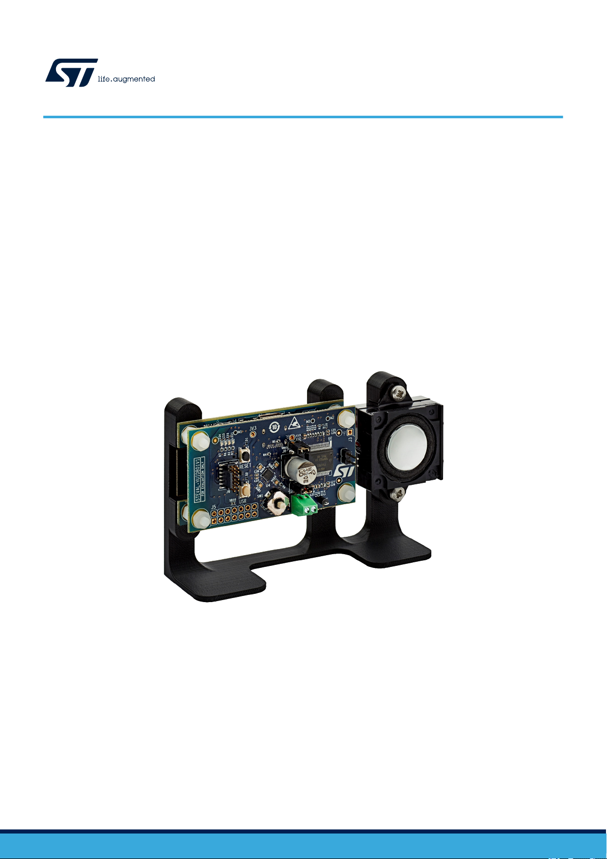
Figure 1. STEVAL-VOICE-UI voice user interface evaluation kit
UM2800 - Rev 1 - November 2020
For further information contact your local STMicroelectronics sales office.
www.st.com
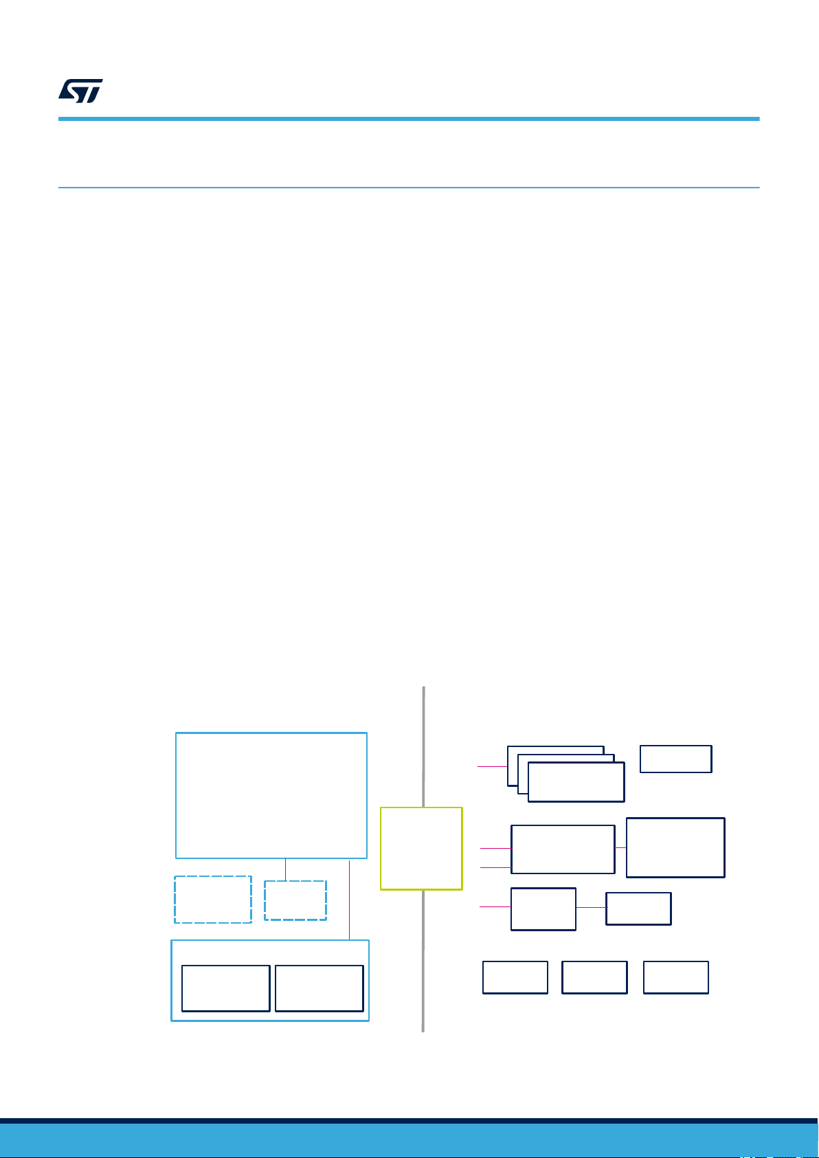
1 Overview
Cortex-M7F@480MHz
1MB RAM
2MB Flash
STM32H753VIT6E
700mA DC-DC
SPI
Murata 1DX
2MB NOR
Flash
STDC14
Led driver
UART
PDM
Joystick
I2C
40pin
conn
(CN1)
USB-C
STSAFE
I2C
Wi-Fi Module
Wi-Fi sub-system
4 LED
(bypass mode)
Audio OUT
ISSI IS25LP016D
I2S
PDM
I2C
UART
STEVAL-VUIDB01V1STEVAL-VUIMB02V1
I2C
I2S
ST1S12GR
LED
4x RGB
2x Buttons
Speaker
output
connector
LED1202
FDA903D
MP23DB01HP
Digital microphone
(Optional)
(Optional)
The STEVAL-VOICE-UI kit features:
• STM32H753VIT6E high-performance MCU with 2 MB embedded Flash, 1 Mb embedded SRAM and in
cost-effective LQFP package
• 2.4 GHz Wi-Fi subsystem with Murata 1DX module used in bypass mode coupled to ISSI IS25LP016D 2
MBytes NOR Flash memory
• 3 x MP23DB01HP MEMS microphones with 36 and 30 mm spacing
• FDA903D class D digital input automotive audio amplifier
• 8 Ohm loudspeaker
• 4 RGB LEDs and 4 simple LEDs
• Joystick, reset and user push buttons
• High modularity with mother/daughter board
• Small 36x65 mm² footprint with simple and cost-effective PCB design
1.1 Kit components
The STEVAL-VOICE-UI kit package includes:
• STEVAL-VUIMB02V1: VUI mother board embedding the STM32H753VIT6E MCU and the Wi-Fi module
• STEVAL-VUIDB01V1: VUI daughter board including the audio front-end (MP23DB01HP microphones and
FDA903D audio amplifier) and the user interface (buttons, joystick, LEDs and USB)
• 8 Ohm speaker
• Mechanical parts
• STLINK-V3MINI debugger/programmer for STM32 with programming cable
• A to C connector cable
UM2800
Overview
1.2
UM2800 - Rev 1
Functional block diagram
Figure 2. STEVAL-VOICE-UI functional block diagram
page 2/34
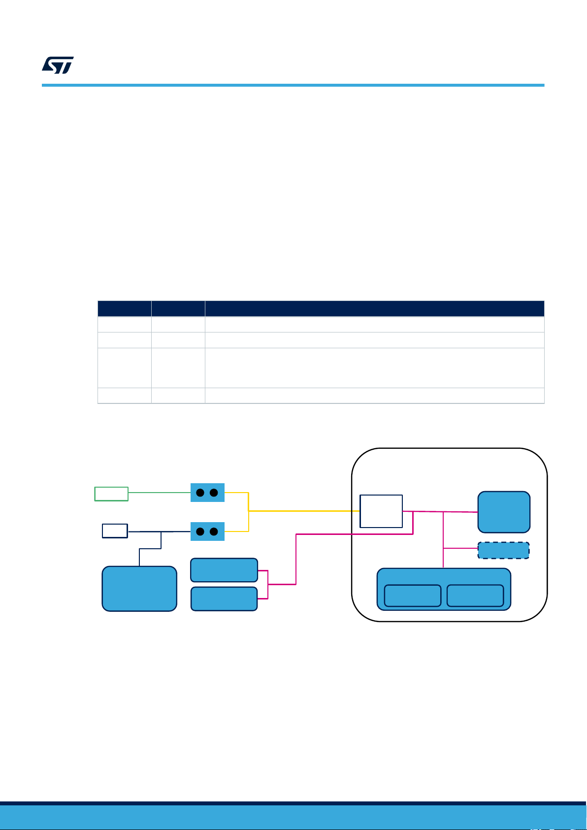
1.3 System requirements
U4
STM32H7
VBUS
J1
MP23DB01HP
LED1202
USB-C
J2
5V
V_PA
STEVAL-VUIMB01V1
Wi-Fi sub-module
STSAFE
FDA903D
Audio Amplifier
STEVAL-VUIDB02V1
Murata 1DX
2MB NOR
3V3
ST1S12
J8
UM2800
System requirements
• Windows® OS (7, 8 and 10), Linux® 64-bit, or MacOS
• html5 web browser version
• Companion app requires Android 7
1.4 Development toolchains
• IAR Systems - IAR Embedded Workbench® EWARM
1.5 Power supply
The easiest way to power the STEVAL-VOICE-UI kit is via the USB-C connector.
J1 J8 Description
CLOSE CLOSE Single power supply from USB. Do not connect V_PA (J2)
CLOSE OPEN Single power supply from V_PA (J2) → up to 5 V
Dual power supply:
OPEN CLOSE
OPEN OPEN 5 V from external source (CN1)
• 5 V from USB
• V_PA from J2 → Up to 18 V
®
Table 1. Power supply options
Figure 3. STEVAL-VOICE-UI power supply block diagram
UM2800 - Rev 1
page 3/34
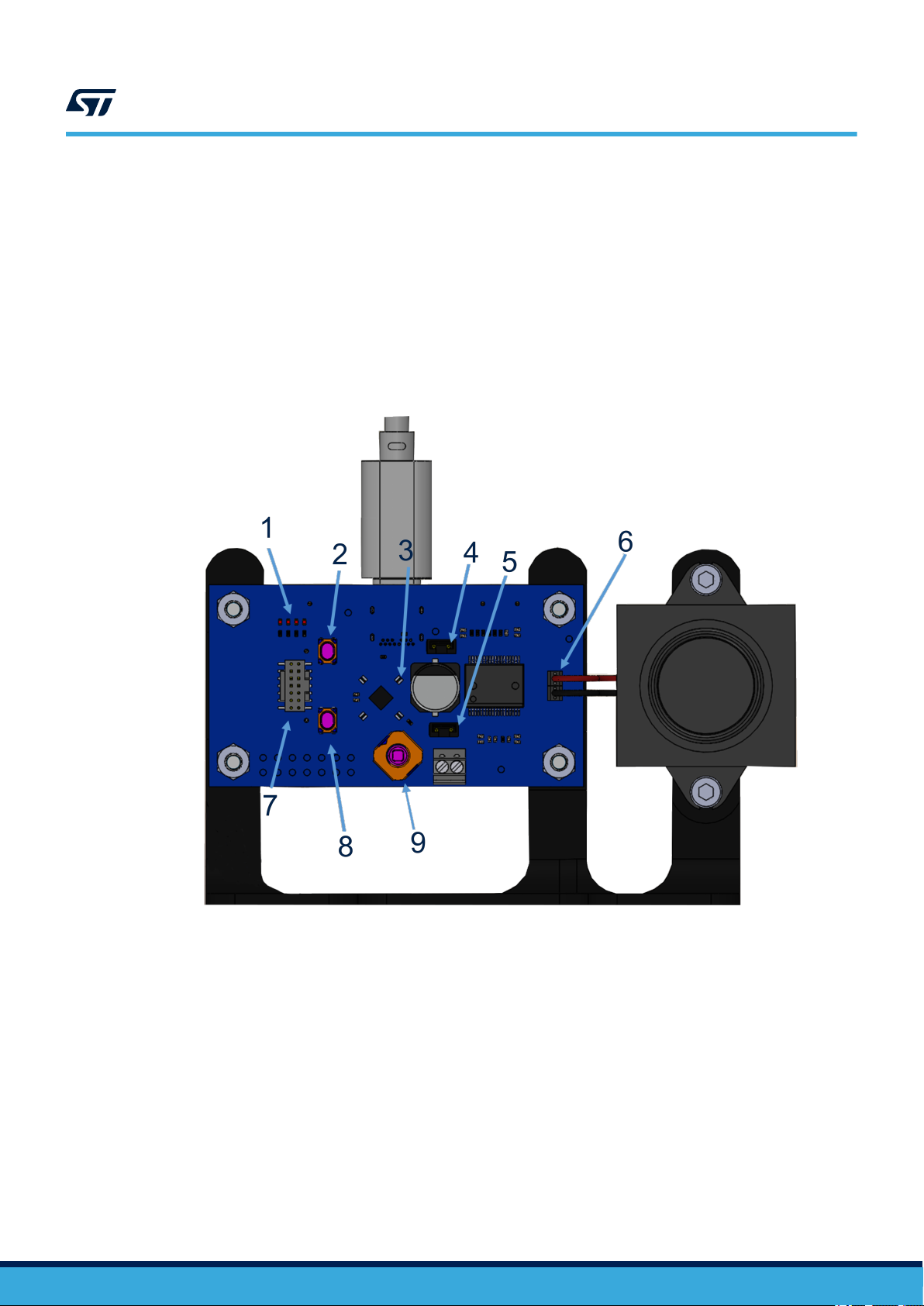
1.6 User interfaces
1. 4 LEDs
2. Reset button
3. 4 RGB LEDs
4. J8
5. J1
6. Loudspeaker terminals
7. Programming connector (STDC14)
8. User button
9. Joystick
UM2800
User interfaces
Figure 4. STEVAL-VOICE-UI user interfaces
UM2800 - Rev 1
page 4/34

2 Demo firmware
2.1 Pre-requisites
The pre-installed ST_VOICE_UI flashed demo firmware demonstrates a voice service solution able to connect to
AVS for AWS IoT.
A direct Internet connection is needed (without proxy).
As an Alexa® device, you need an Amazon™ account to connect to AVS for AWS IoT service.
The account can be created on www.amazon.com or other local versions.
The users who have registered to Amazon Music service will be able to play music on the device.
2.2 Device setup
Step 1. Power the device through a USB C cable.
Step 2. Configure the network connection.
Step 3. Register to AVS for AWS IoT service.
2.2.1 Android users
For Android users, the stvsSmartConfig companion app is available on Google Store and allows configuring the
device. The application is also available in the software delivery package for manual installation.
UM2800
Demo firmware
UM2800 - Rev 1
page 5/34
UM2800
Device setup
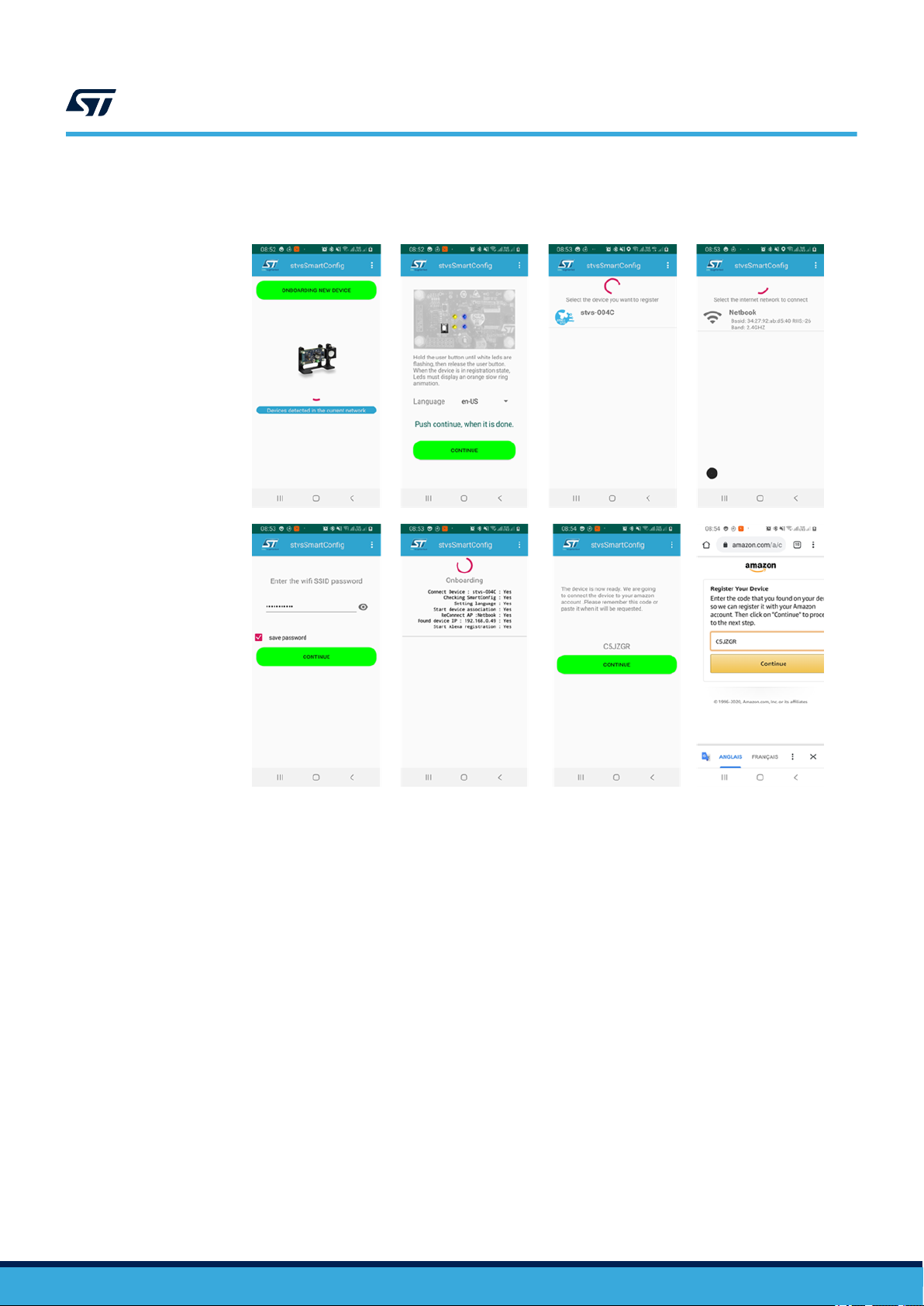
Step 1. To configure a new device, push the [Onboarding new device] button and follow the instructions.
Figure 5. stvsSmartConfig procedure
2.2.2 Other users - HTTP UI
The device embeds an HTTP service that the consumer can connect to via smartphone or PC and an HTML5
browser (Safari or Chrome). To connect to the server, the smartphone must be connected to the same Wi-Fi spot
of the board.
The HTTP UI interface tab allows checking the service status and changing some configurations.
Two cases must be distinguished:
1. Wi-Fi connection
2. Other connections (Wi-Fi information already logged in)
2.2.2.1 Wi-Fi connection
Step 1. Ensure the device is in Access Point (AP) mode.
Step 1a. Check the current mode using the RGB LEDs (see Table 2).
Step 1b. If not in AP mode, refer to Section 2.9 .
Step 2. Connect your phone/PC navigator to 192.168.0.1.
Step 3. Follow the procedure described in Section 2.2.2.1.1 .
2.2.2.1.1 Wi-Fi configuration
By default, the device comes in Wi-Fi AP mode and offers a hotspot whose name looks like stvs-xxxx.
Step 1. Connect your PC or smartphone to the hotspot and then connect the browser to the address
192.168.0.1.
UM2800 - Rev 1
page 6/34
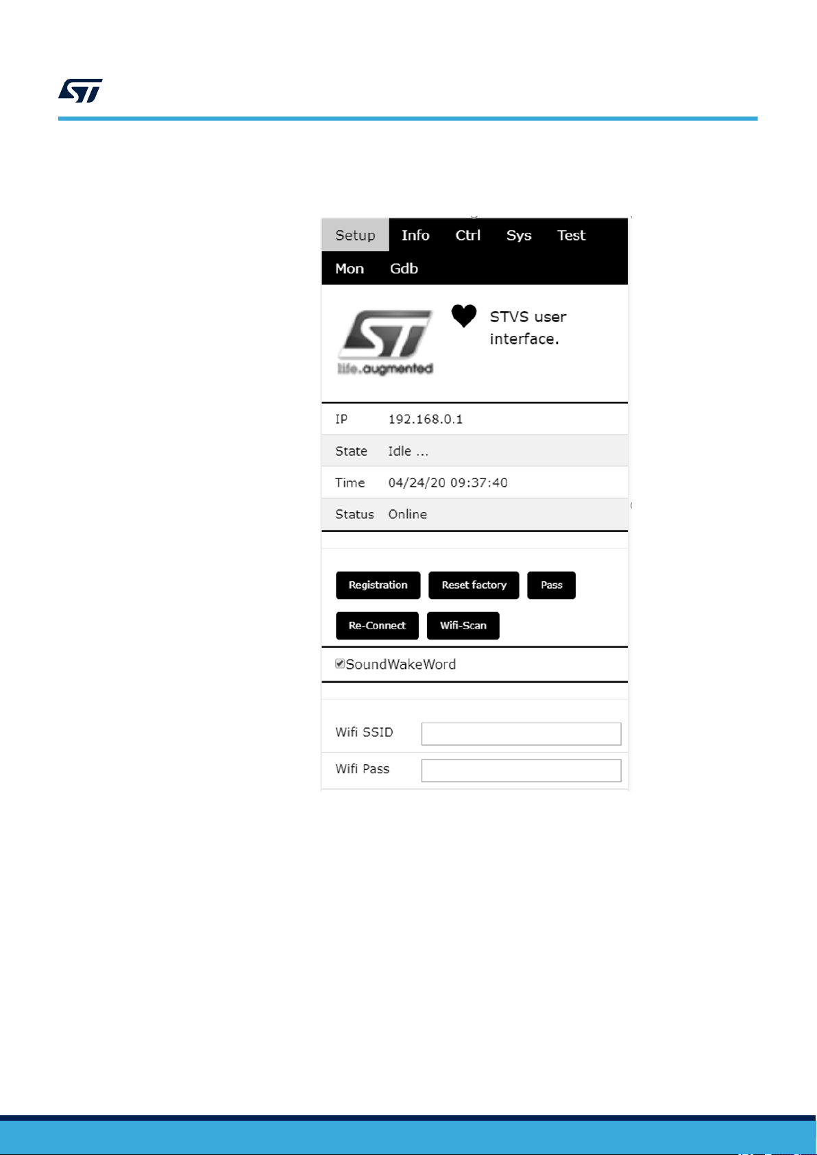
Step 2. Go to STVS UI [Setup] tab.
UM2800
Device setup
Figure 6. STVS user interface
2.2.2.2
UM2800 - Rev 1
Step 3. Push the [Wi-Fi-Scan] button.
All visible spots will be listed in the scan results.
Step 4. Scroll down and select your home network (in this case the hotspot is called [Netbook]).
Step 5. Scroll back and type the Wi-Fi password.
Step 6. Scroll down and select the connection type ([Wi-Fi STA].
Step 7. To connect the board, scroll up and select [Re-connect].
Step 8. Check RGB LEDs on the board (see Table 2).
After few seconds, the Wi-Fi state should switch from “disconnected” to “connected “.
The board reboots and connects to the network via Wi-Fi using a new IP address.
Connection to Wi-Fi STA
In this case, hotspot Wi-Fi information has already been configured and the board is properly connected to it
(refer to Section 2.2.2.1.1 , step 6).
page 7/34

Step 1. Get the board IP address available in the serial console.
Step 2. Refer to Section 2.11 to access the traces.
Note: Traces with the IP address looks like:
00:00:00 : 192.168.X.X : 06:STVS_EVT_NETWORK_IP(0x3001D5BC)
The IP is no longer in the AP mode (address = 192.168.0.1).
Step 3. Connect to the UI using the given address.
Step 4. If there is no serial console connected to the board, scan the network using a free application.
Once installed, the application shows all STVS devices available in the neighborhood and allows
connecting to them:
– iPhone users can install “Bonjour HTTP search” from the App Store;
– Android users can download “BonjourBrowser” from the Android Store;
– PC users can install “bonjour browser” from www.tildesoft.com.
2.3 Device registration
Step 1. From www.amazon.com or local Amazon server, create an Amazon account.
UM2800
Device registration
Step 2. Under [Setup] tab, click [Registration](HTML5 browser required).
The browser will display a code and a link (amazon.com/code).
UM2800 - Rev 1
page 8/34
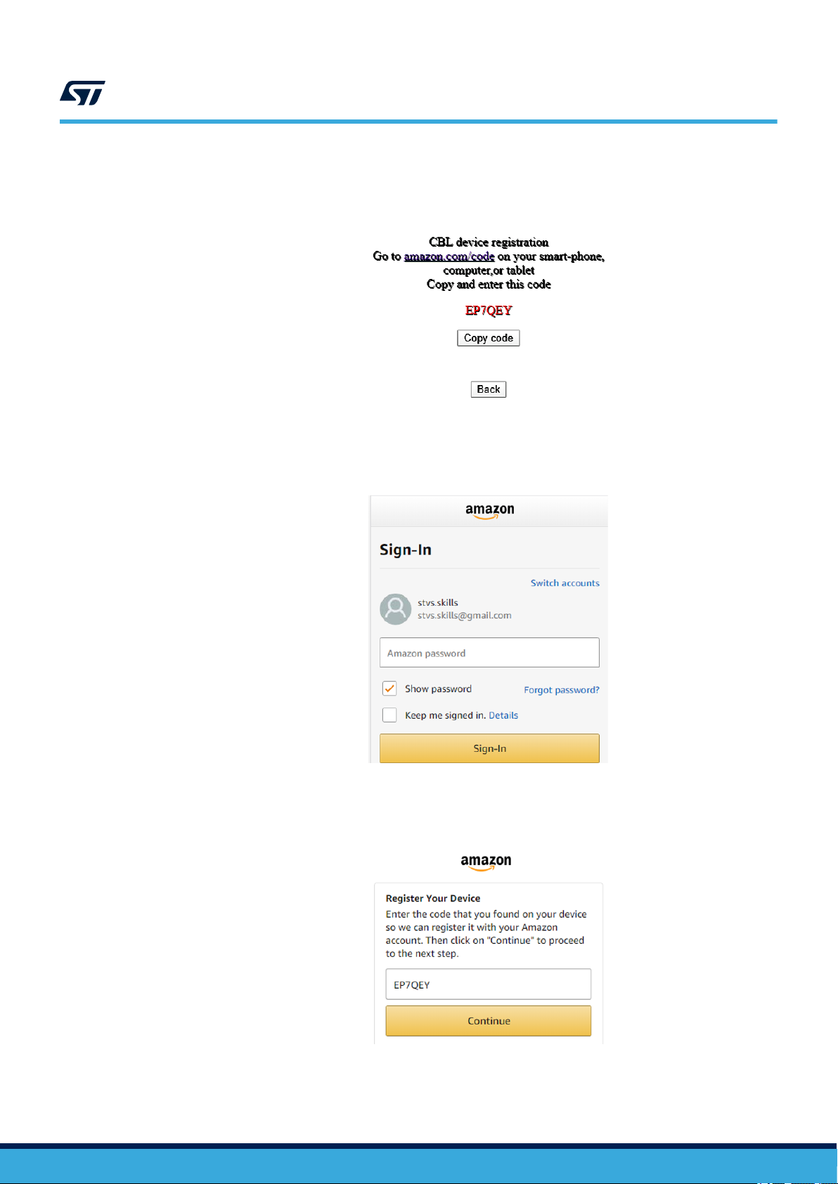
Step 3. Copy the code and click on the link.
Figure 7. CBL device registration code
You will be redirected to an Amazon sign-in page.
UM2800
Device registration
Figure 8. Amazon sign-in page
UM2800 - Rev 1
Step 4. Enter you Amazon credentials.
If credentials are correct, you will be redirected to the following page.
Figure 9. Register device page
page 9/34
Step 5. Past or enter the code given in the previous page and click on continue.
If this step is successful, the board connects to AVS for AWS IoT and the LEDs turns off after few
seconds.
Now you can test the device. You can talk to Alexa (for example, asking: “Alexa, what time is it ?”)
2.4 Privacy mode
UM2800
Privacy mode
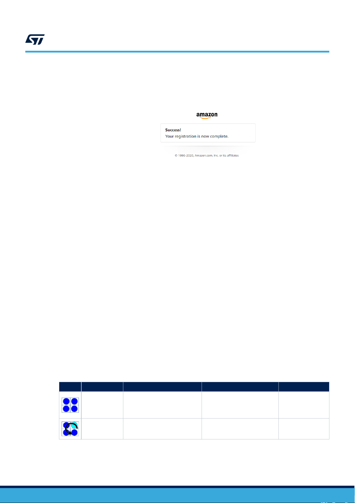
Figure 10. Successful registration
The device enters privacy mode when you briefly push the white user button.
A red LED switches on and the device does not send any other audio request to the cloud, even when saying
"Alexa".
2.5 Alarms
When an alarm or a timer is set and the device rings, you have to press the joystick to acknowledge and stop the
alert.
Example of voice requests:
• “Alexa set a timer for 2 minutes”;
• “Alexa set an alarm at 5 pm”;
• “Alexa set alarm” → Alexa will ask for details.
2.6 Amazon music control
If the Amazon account used to register the board is registered to Amazon music, it is possible to ask Alexa to play
some songs or playlists and navigate it.
The joystick is also used to navigate music playlists.
2.7 LED UI animations
Table 2. RGB LED animations indicating device state
Effects Color Internal service ID Animation Comment
Blue Restarting Solid
Blue/Cyan Booting Normal beat
Just after the reset.
It remains like this
until the first event is
dispatched.
It remains like this
during the basic
system initialization.
UM2800 - Rev 1
page 10/34
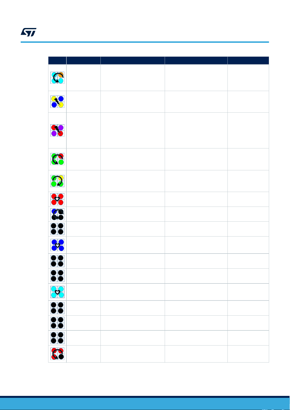
UM2800
LED UI animations
Effects Color Internal service ID Animation Comment
It signals a
Cyan/Orange configuration_changes Normal beat
Blue/Yellow has_ip Very fast blinking
Red/Purple error_need_credentials Fast blinking
Green/Red
Yellow/Green connecting Fast counterclockwise rotation
error_need_registration Slow rotation
configuration state,
mainly when the
board is in Access
Point mode.
During the boot, it
signals by a sort
event that the network
has an IP address.
It signals an error,
the system needs
AWS and AVS
credentials. It should
occur only during
test and development
configuration.
It signals an error.
The system needs an
AVS registration (refer
to Section 2.3 ).
It signals a
reconnection to the
AVS for AWS IoT
service.
Red Privacy Very long pulsation
Blue/Black Wakeup Very fast rotation
Black Idle All off
Blue activeListening Very long pulsation
Black stopListening All off Not signalled yet.
Black startListening All off Not signalled yet.
Cyan activeSpeaking Very very long pulsation
Black stopSpeaking All off Not signalled yet.
Black startSpeaking All off Not signalled yet.
Black thinking All off Not signalled yet.
It signals the privacy
mode is ON.
Short signal when a
Wakeup occurs.
It signals the board is
ready for interactions.
The AVS for AWS IoT
service is listening for
utterance.
The AVS for AWS IoT
service is speaking or
playing.
UM2800 - Rev 1
Red/Black alerting Slow counterclockwise rotation
A timer/alarm/
notification/remember
is triggered.
page 11/34
 Loading...