

Page 1
UM2777
User manual
How to use the STEVAL-STWINKT1B SensorTile Wireless Industrial Node for
condition monitoring and predictive maintenance applications
Introduction
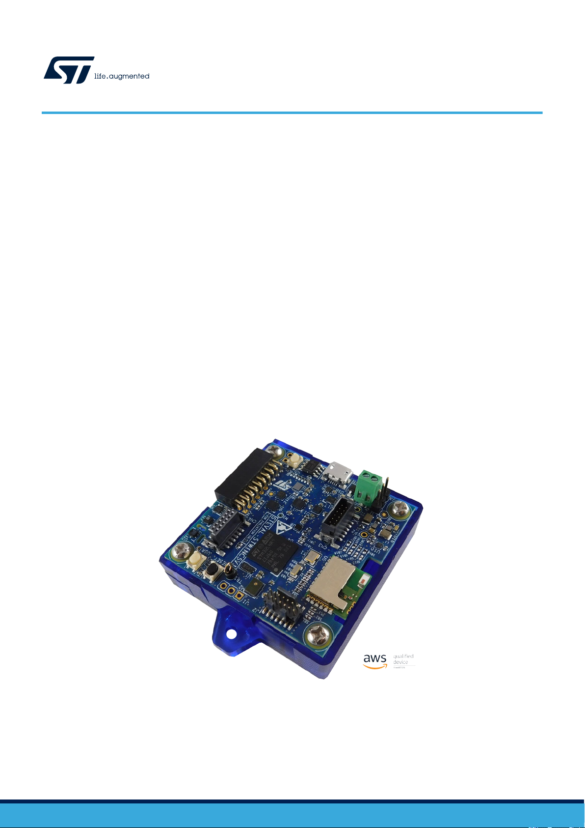
The STWIN SensorT
simplifies prototyping and testing of advanced industrial IoT applications such as condition monitoring and predictive
maintenance.
It is the updated version of STEVAL-STWINKIT1, now including STSAFE-A110 populated, BlueNRG-M2SA module and
IMP23ABSU MEMS microphone.
The kit features a core system board with a range of embedded industrial-grade sensors and an ultra-low-power microcontroller
for vibration analysis of 9-DoF motion sensing data across a wide range of vibration frequencies, including very high frequency
audio and ultrasound spectra, and high precision local temperature and environmental monitoring.
The development kit is complemented with a rich set of software packages and optimized firmware libraries, as well as a cloud
dashboard application, all provided to help speed up design cycles for end-to-end solutions.
The kit supports Bluetooth® low energy wireless connectivity through an on-board module, and Wi-Fi connectivity through
a special plugin expansion board (STEVAL-STWINWFV1). Wired connectivity is also supported via an on-board RS485
transceiver. The core system board also includes an STMod+ connector for compatible, low cost, small form factor daughter
boards associated with the STM32 family, such as the LTE Cell pack.
Apart from the core system board, the kit is provided complete with a 480 mAh Li-Po battery, an STLINK-V3MINI debugger and
a plastic box.
ile wireless industrial node (STEVAL-STWINKT1B) is a development kit and reference design that
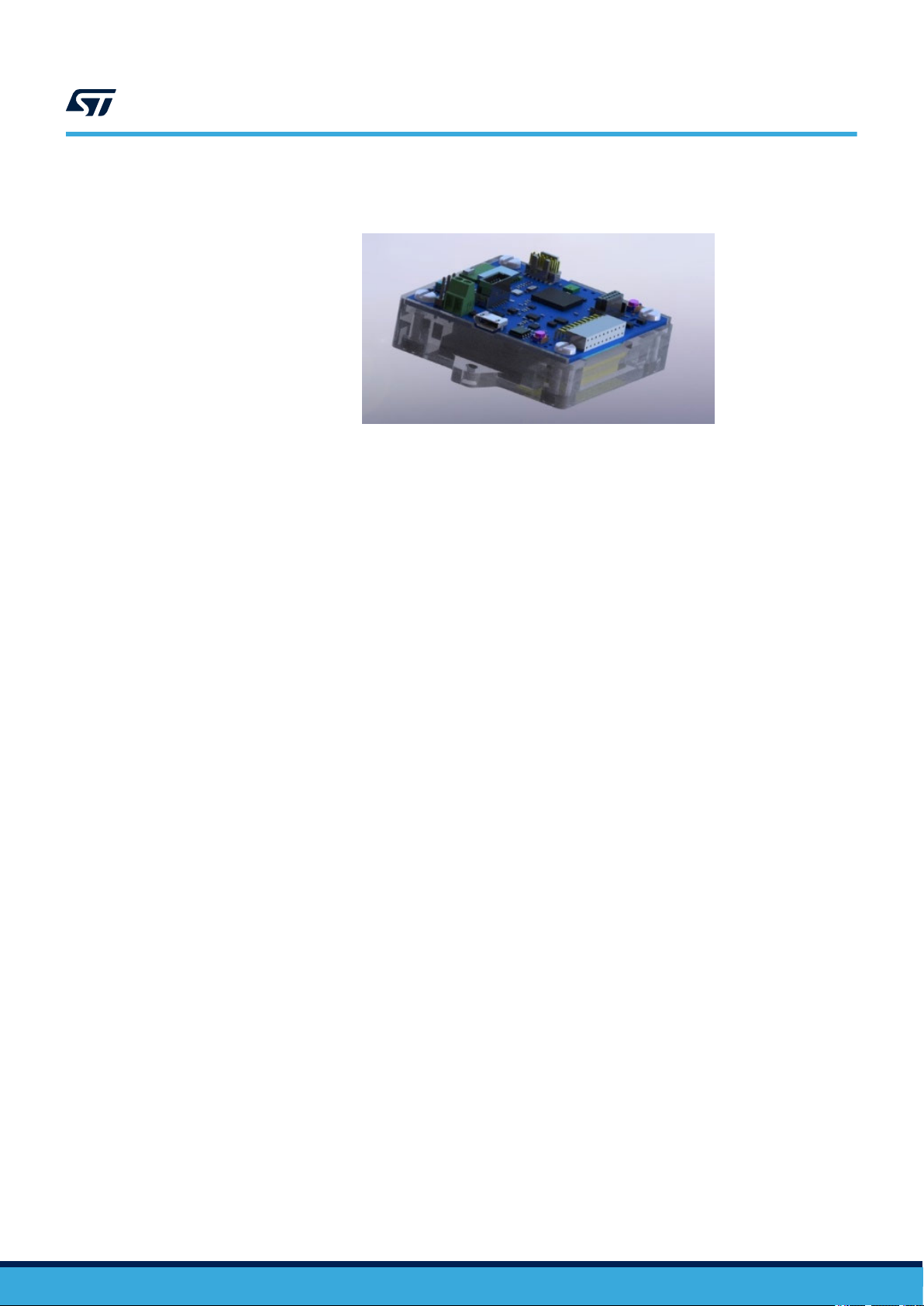
Figure 1. STEVAL-STWINKT1B SensorTile Wireless Industrial Node
UM2777 - Rev 2 - January 2021
For further information contact your local STMicroelectronics sales of
fice.
www.st.com
Page 2
1 STWIN kit components
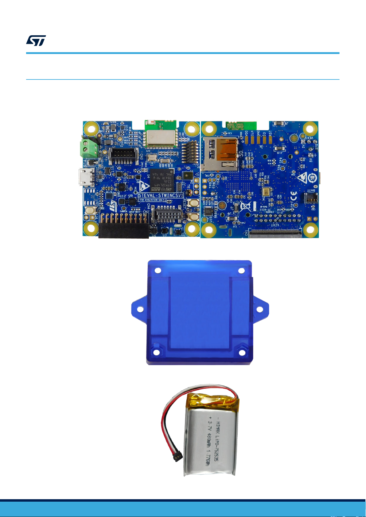
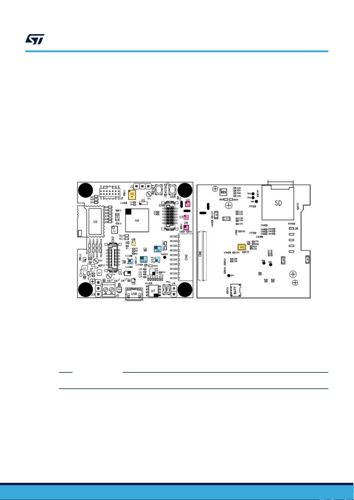
The SensorTile Wireless Industrial Node (STWIN) is packaged with the components shown below.
Figure 2. STWIN Core System board top and bottom
UM2777
STWIN kit components
Figure 3. Protective plastic case
Figure 4. 480mAh 3.7V Li-Po Battery
UM2777 - Rev 2
page 2/45
Page 3
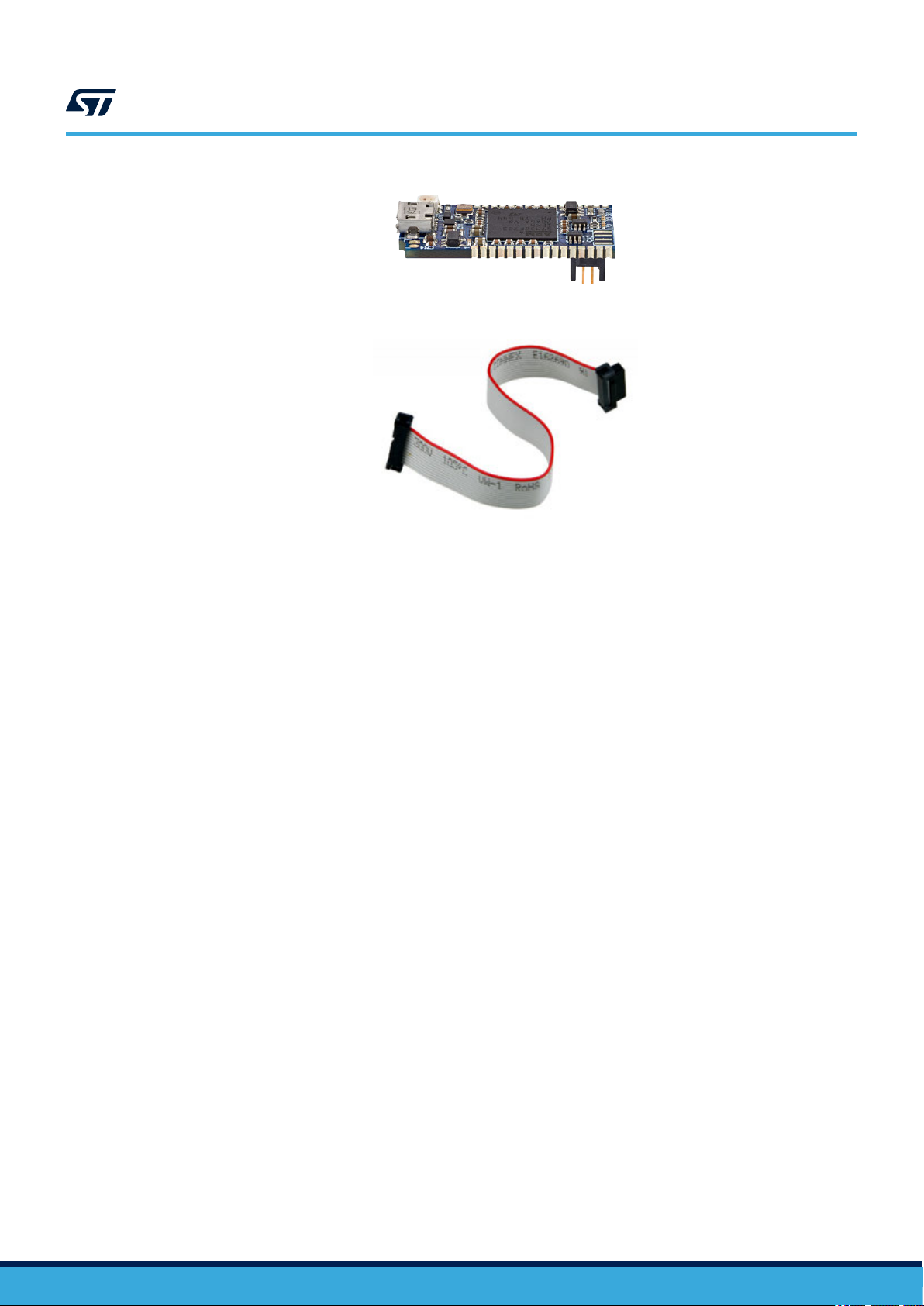
Figure 5. STLink-V3Mini Debugger/Programmer for STM32
Figure 6. Programming cable
UM2777
STWIN kit components
UM2777 - Rev 2
page 3/45
Page 4
2 Functional blocks
SPI3
ADC1
USART2
Enanced
SWD
Connector
UART5
I2C2
ADC3
GPIO
Auxiliary
Connector
DFSDM1
I2C2
IMP34DT05
Digital Microphone
LPS22HH
Pressure Sensor
HTS221
Humidity and
Temperature Sensor
STTS751
Temperature Sensor
IIS2MDC
3D Magnetometer
STM32L4R9ZIJ6
Microcontroller
Ultra Low Power
Cortex M4F@120MHz
32 kHz
Crystal
16 MHz
Crystal
BlueNRG-M2SA
Bluetooth® low energy
Application Processor Module
STR485LV
RS485 Interface
SPI2
IMP23ABSU
Analog Microphone
TS922EIJT
Low noise, low
distortion OpAmp
20-pin STMOD+
12-pin female sensor
connector
12-pin male
connector
40-pin Flex
STSAFE
Secure Element*
I2C2
SPIx, I2S,
USARTx,...
IIS2DH
3D Accelerometer
IIS3DWB
Vibrometer
ISM330DHCX
6-Axis IMU
USBLC6-2P6
USB ESD protection
ESDALC6V1-1U2
Single Line ESD
protection
EMIF06-MSD02N16
EMI filter and ESD
protection
STBC02
Li-Ion linerar battery
charger
ST1PS01EJR
step-down switching
regulator
LDK130
Low Noise LDO
Sensing
Processing
Connectivity
Power Mng.
Analog
Secure
* not mounted
connector
connector
SPI3
ADC1
I2C2
IMP34DT05
Digital Microphone
LPS22HH
Pressure Sensor
HTS221
Humidity and
Temperature Sensor
STTS751
Temperature Sensor
IIS2MDC
3D Magnetometer
STM32L4R9ZIJ6
Microcontroller
Ultra Low Power
Cortex M4F@120MHz
IMP23ABSU
Analog Microphone
TS922EIJT
Low noise, low
distortion OpAmp
IIS2DH
3D Accelerometer
IIS3DWB
Vibrometer
ISM330DHCX
6-Axis IMU
Sensing
Analog
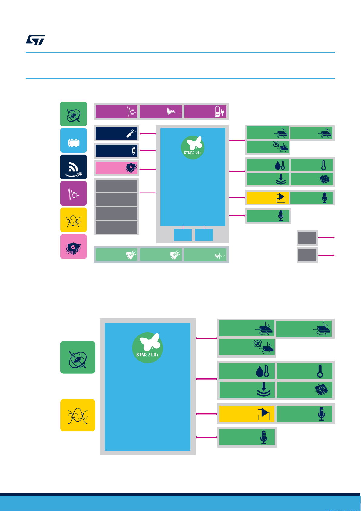
Figure 7. STEVAL-STWINKT1B functional block diagram
UM2777
Functional blocks
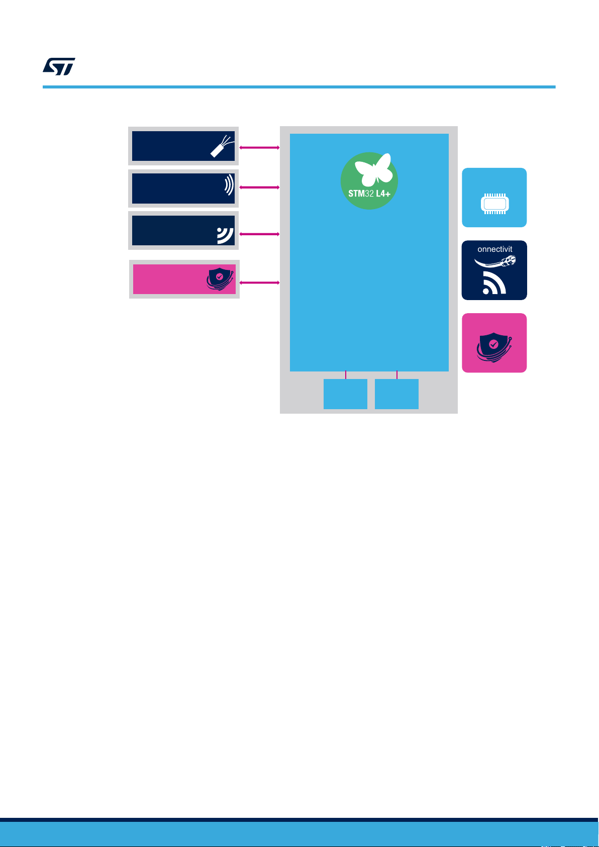
2.1 Sensing
The core system board offers a comprehensive range of sensors specifically designed to support and enable the
Industry 4.0 applications.
Figure 8. STEVAL-STWINKT1B functional block diagram of sensing elements and STM32L4R9ZIJ6
UM2777 - Rev 2
DFSDM1
page 4/45
Page 5
UM2777
Sensing
The motion sensors communicate with the STM32L4R9ZIJ6 microcontroller via SPI in order to accommodate the
high data rates, while the magnetometer and environmental sensors communicate via I2C.
The suitably filtered signal from the IMP23ABSU
and then sampled by the internal 12-bit ADC in the MCU, while the signal from digital microphone is directly
managed by the digital filter for Sigma-Delta modulators (DFSDM) interface in the MCU.
Figure 9. Core system board sensor locations
U2: HTS221 relative humidity and temperature sensor
U3: LPS22HH digital absolute pressure sensor
U6: STTS751 low-voltage digital local temperature sensor
U8: TS922 rail-to-rail, high output current, dual operational amplifier
U9: ISM330DHCX 3D acc. + 3D gyro iNEMO IMU with machine learning core
U11: IIS3DWB ultra-wide bandwidth (up to 6 kHz), low-noise, 3-axis digital vibration sensor
U12: IIS2DH ultra-low-power high performance MEMS motion sensor
U13: IIS2MDC ultra-low-power 3-axis magnetometer
M1: IMP23ABSU analog MEMS microphone
M2: IMP34DT05 industrial grade digital MEMS microphone
analog microphone is amplified by a TS922 low noise op-amp
2.1.1 HTS221 humidity and temperature sensor
The HTS221
signal ASIC to provide measurement information through digital serial interfaces.
The sensing element consists of a polymer dielectric planar capacitor structure capable of detecting relative
humidity variations and is manufactured using a dedicated ST process.
The HTS221 is available in a small top-holed cap land grid array (HLGA) package guaranteed to operate over a
temperature range from -40 °C to +120 °C.
is an ultra-compact relative humidity and temperature sensor with a sensing element and a mixed
RELATED LINKS
Visit the product web page for the HTS221 relative humidity and temperature sensor
2.1.2 LPS22HH MEMS pressure sensor
The LPS22HH is an ultra-compact piezoresistive absolute pressure sensor which functions as a digital output
barometer
I3CSM or SPI from the sensing element to the application.
The sensing element, which detects absolute pressure, consists of a suspended membrane manufactured using a
dedicated process developed by ST.
The LPS22HH is available in a full-mold, holed LGA package (HLGA). It is guaranteed to operate over a
temperature range extending from -40 °C to +85 °C.
. The device consists of a sensing element and an IC interface which communicates through I²C, MIPI
UM2777 - Rev 2
page 5/45
Page 6

RELATED LINKS
Visit the product web page for the LPS22HH MEMS pressure sensor
2.1.3 STTS751 digital temperature sensor
The STTS751
The temperature is measured with a user-configurable resolution between 9 and 12 bits. At 9 bits, the smallest
step size is 0.5 °C, and at 12 bits, it is 0.0625 °C. At the default resolution (10 bits, 0.25 °C/LSB), the nominal
conversion time is 21 milliseconds.
Up to eight devices can share the same 2-wire SMBus without ambiguity, allowing a single application to monitor
multiple temperature zones.
is a digital temperature sensor which communicates over a 2-wire SMBus 2.0 compatible bus.
RELATED LINKS
Visit the product web page for the STTS751 digital temperature sensor
2.1.4 TS922 rail-to-rail, high output current, dual operational amplifier
The TS922 is a rail-to-rail dual BiCMOS operational amplifier optimized and fully specified for 3 V and 5 V
operation. The very low noise, low distortion, low of
highly suitable for high quality, low voltage, or battery operated audio systems.
fset, and high output current capability render this device
UM2777
Sensing
RELATED LINKS
Visit the product web page for the TS922 rail-to-rail, high output current, dual operational amplifier
2.1.5 ISM330DHCX iNEMO IMU 3D Acc + 3D Gyro
The ISM330DHCX is a system-in-package featuring a high-performance 3D digital accelerometer and +3D digital
gyroscope tailored for Industry 4.0 applications.
The sensing elements of the accelerometer and of the gyroscope are implemented on the same silicon die, which
ensures superior stability and robustness.
Several embedded features such as programmable FSM, FIFO, sensor hub, event decoding and interrupts allow
the implementation of smart and complex sensor nodes able to deliver high performance at very low power
RELATED LINKS
Visit the product web page for the ISM330DHCX iNEMO IMU 3D Acc + 3D Gyro
2.1.6 IIS3DWB ultra-wide bandwidth (up to 6 kHz), low-noise, 3-axis digital vibration sensor
The IIS3DWB is a system-in-package featuring a 3-axis digital accelerometer with low noise over an ultra-wide
and flat frequency range. The wide bandwidth, low noise, very stable and repeatable sensitivity
the capability of operating over an extended temperature range (up to +105 °C), render the device particularly
suitable for vibration monitoring in industrial applications.
The high performance delivered at low power consumption, together with the digital output and embedded digital
features like FIFO and interrupts are of primary importance in battery-operated industrial wireless sensor nodes.
, together with
.
RELATED LINKS
Visit the product web page for the IIS3DWB ultra-wide bandwidth (up to 6 kHz), low-noise, 3-axis digital vibration sensor
2.1.7 IIS2DH ultra-low power 3-axis high-performance accelerometer
The IIS2DH
interface standard output.
The device may be configured to generate interrupt signals from two independent inertial wake-up/free-fall events,
as well as from the position of the device itself.
UM2777 - Rev 2
is an ultra-low-power high-performance three-axis linear accelerometer with digital I2C/SPI serial
page 6/45
Page 7

UM2777
Processing and connectivity
RELATED LINKS
Visit the product web page for the IIS2DH ultra-low power 3-axis high-performance accelerometer
2.1.8 IIS2MDC 3-axis magnetometer
The IIS2MDC is a high-accuracy
range up to ±50 gauss, and includes an I²C serial bus interface that supports 100 kHz, 400 kHz, 1 MHz, and
3.4 MHz rates and an SPI serial standard interface.
The device can be configured to generate an interrupt signal from magnetic field detection.
RELATED LINKS
Visit the product web page for the IIS2MDC 3-axis magnetometer
2.1.9 IMP23ABSU analog MEMS microphone with extended frequency response up to 80 kHz for
ultrasound applications
The IMP23ABSU is a compact, low-power microphone based on a capacitive sensing element and an IC
interface.
The sensing element can detect acoustic waves and is manufactured using a special silicon micro-machining
process to produce audio sensors.
The IMP23ABSU has an acoustic overload point of 130 dBSPL with a typical 64 dB signal-to-noise ratio.
The IMP23ABSU sensitivity is -38 dBV ±1 dB at 94 dBSPL, 1 kHz.
The IMP23ABSU is available in a package compliant with re-flow soldering and is guaranteed to operate over an
extended temperature range (-40 to +85 °C).
, ultra-low-power 3-axis digital magnetic sensor. It has a magnetic field dynamic
RELATED LINKS
Visit the product web page for the IMP23ABSU analog MEMS microphone
2.1.10 IMP34DT05 digital MEMS microphone
The IMP34DT05 is an ultra-compact, low-power
sensing element and an IC interface; the device features 64 dB signal-to-noise ratio and -26 dBFS ±3 dB
sensitivity.
The IC interface includes a dedicated circuit able to provide a digital signal externally in PDM format.
RELATED LINKS
Visit the product web page for the IMP34DT05 digital MEMS microphone
2.2 Processing and connectivity
The STWIN core system board features several wired and wireless connectivity options and the STM32L4R9ZI
ultra-low-power microcontroller
Cortex-M4 32-bit RISC core, operating at up to 120 MHz and equipped with 640 Kb SRAM and 2 MB Flash
memory.
, which is part of the STM32L4+ series MCUs based on the high-performance Arm
, omnidirectional, digital MEMS microphone built with a capacitive
UM2777 - Rev 2
page 7/45
Page 8
USART2
STM32L4R9ZIJ6
Microcontroller
Ultra Low Power
Cortex M4F@120MHz
32 kHz
Crystal
16 MHz
Crystal
BlueNRG-M2SA
Bluetooth low energy
Application Processor Module
STR485LV
RS485 Interface
SPI2
SPI1
Secure
Processing
Connectivity
STEVAL-STWINWFV1
12-pin male com.
connector
STSAFE
Secure Element*
I2C2
Processing and connectivity
Figure 10. Main connectivity components and the STM32L4R9ZI processing unit
UM2777
Each connectivity component is connected to an independent bus on the STM32L4R9ZI MCU, so they can all be
configured individually.
UM2777 - Rev 2
page 8/45
Page 9
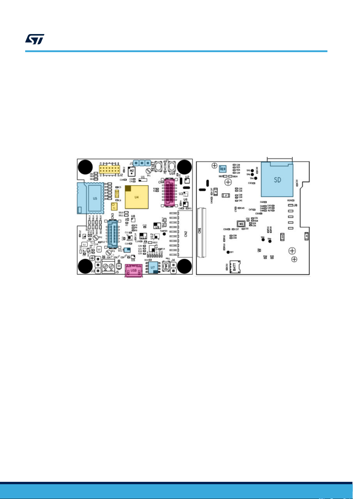
Figure 11. MCU and connectivity element locations
U4: STM32L4R9ZI Cortex-M4F 120MHz 640Kb RAM
U5: BlueNRG-M2SA V
U7: STSAFE-A110 authentication and brand protection secure solution
U17: STG3692 high bandwidth quad SPDT switch
U19: STR485 3.3V RS485 up to 20Mbps
USB: Micro-USB connector (power supply + data)
X1: 16MHz crystal oscillator
X2: 32.768 kHz crystal oscillator
J2: STDC14 programming connector for STLINK-V3
J1: RS485 interface header connector
CN3: Connectivity expansion connector (for STEVAL-STWINWFV1)
CN4: Audio/sensor expansion connector
SD: microSD card socket
ery low power application processor module for Bluetooth® low energy v5.0
UM2777
Processing and connectivity
2.2.1 STM32L4R9ZI Cortex-M4F 120MHz 640Kb RAM
The STM32L4R9ZI devices is an ultra-low-power microcontroller (STM32L4+ Series MCU) based on the highperformance Arm Cortex-M4 32-bit RISC core, which operates at a frequency of up to 120 MHz.
The Cortex-M4 core features a single-precision floating-point unit (FPU), which supports all the Arm singleprecision data-processing instructions and all the data types. The Cortex-M4 core also implements a full set of
DSP (digital signal processing) instructions and a memory protection unit (MPU) which enhances application
security.
These devices embed high-speed memories (2 Mbytes of Flash memory and 640 Kbytes of SRAM), a flexible
external memory controller (FSMC) for static memories (for devices with packages of 100 pins and more), two
OctoSPI Flash memory interfaces and an extensive range of enhanced I/Os and peripherals connected to two
APB buses, two AHB buses and a 32-bit multi-AHB bus matrix.
The MCU embeds several protection mechanisms for embedded Flash memory and SRAM: readout protection,
write protection, proprietary code readout protection and a firewall.
These devices offer a fast 12-bit ADC (5 Msps), two comparators, two operational amplifiers, two DAC channels,
an internal voltage reference buffer, a low-power RTC, two general-purpose 32-bit timer, two 16-bit PWM timers
for motor control, seven general-purpose 16-bit timers, and two 16-bit low-power timers. The devices support four
digital filters for external sigma delta modulators (DFSDM). In addition, up to 24 capacitive sensing channels are
available.
They also feature standard and advanced communication interfaces such as:
• Four I2Cs
• Three SPIs
• Three USARTs, two UARTs and one low-power UART
• Two SAIs
• One SDMMC
UM2777 - Rev 2
page 9/45
Page 10

UM2777
Processing and connectivity
• One CAN
One USB OTG full-speed
•
• Camera interface
• DMA2D controller
The device operates in the -40 to +85 °C (+105 °C junction) and -40 to +125 °C (+130 °C junction) temperature
ranges from a 1.71 to 3.6 V for VDD power supply when using internal LDO regulator and a 1.05 to 1.32 V V
power supply when using external SMPS supply. A comprehensive set of power-saving modes allows the design
of low-power applications.
Some independent power supplies are supported, such as an analog independent supply input for ADC, DAC,
OPAMPs and comparators, a 3.3 V dedicated supply input for USB and up to 14 I/Os, which can be supplied
independently down to 1.08 V. A VBAT input allows backup of the RTC and the registers. Dedicated V
supplies can be used to bypass the internal LDO regulator when connected to an external SMPS.
RELATED LINKS
Visit the product web page for the STM32L4R9ZI micrcontroller
2.2.2 BlueNRG-M2 very low power application processor module for Bluetooth® low energy v5.0
The BlueNRG-M2 is a Bluetooth®
with BT specifications v5.0 and BQE qualified. The module simultaneously supports multiple roles and can act at
the same time as Bluetooth master and slave device.
The BlueNRG-M2 is based on the BlueNRG-2 system-on-chip and provides a complete RF platform in a tiny
form factor, integrating radio, embedded antenna and high frequency oscillators to offer a certified solution that
optimizes the final application time-to-market.
The BlueNRG-M2 can be directly powered by a pair of AAA batteries or any power source from 1.7 to 3.6 V.
low energy system-on-chip application processor certified module compliant
DD12
power
DD12
RELATED LINKS
Visit the product web page for the BlueNRG-M2SA application module for Bluetooth® low energy v5.0 wireless technology
2.2.3 STEVAL-STWINWFV1 Wi-Fi expansion (not included in the kit) for the SensorTile wireless
industrial node (STWIN) kit
The STEV
Wireless Industrial Node (STWIN) kit.
Through the CN3 connectivity expansion connector, the STEVAL-STWINWFV1 can be plugged into the STWIN
core system board.
It is based on the ISM43362-M3G-L44-E Wi-Fi module and its main features are:
• 802.11 b/g/n compatible
• based on Broadcom MAC/Baseband/Radio device
• fully contained TCP/IP stack
• host interface: SPI up to 25 MHz
The RF power emitted is +9 dBm (limited by firmware).
The module operating band is 2400 MHz ~ 2483.5 MHz (2.4 GHz ISM Band).
AL-STWINWFV1 expansion board (sold separately) adds 2.4 GHz Wi-Fi connectivity to the SensorTile
RELATED LINKS
Visit the product web page for further details on the STEVAL-STWINWFV1
2.2.4 STR485LV 3.3V RS485 up to 20Mbps
The STR485 is a low power dif
half-duplex mode. Data and enable signals are compatible with 1.8 V or 3.3 V supplies.
ferential line transceiver for RS485 data transmission standard applications in
UM2777 - Rev 2
page 10/45
Page 11

Power management
Two speeds are selectable via the SLR pin: fast data rate up to 20 Mbps or slow data rate up to 250 kbps for
extended cables.
Excessive power dissipation caused by bus contention or faults is prevented by a thermal shutdown circuit that
forces the driver outputs into a high impedance state. The receiver has a fail-safe feature that guarantees a high
output state when the inputs are left open, shorted or idle.
RELATED LINKS
Visit the product web page for the STR485LV 3.3V RS485 up to 20Mbps
2.2.5 USB connector
The Micro-USB connector on the board can be used for both power supply and data transfer (USB Device only).
Dif
ferent examples of USB class implementation can be found in STSW-STWINKT01 software package.
2.2.6 STSAFE-A110 authentication, state-of-the-art security for peripherals and IoT devices
The STSAFE-A1
data management services to a local or remote host. It consists of a full turnkey solution with a secure operating
system running on the latest generation of secure microcontrollers.
The STSAFE-A110 can be integrated in IoT devices, smart-home, smart-city and industrial applications,
consumer electronics devices, consumables and accessories.
10 is a highly secure solution that acts as a secure element providing authentication and secure
UM2777
RELATED LINKS
Visit the product web page for the STSAFE-A110 authentication, state-of-the-art security for peripherals and IoT devices
2.2.7 microSD card socket
On the bottom side of the STWIN core system board is a microSD Card socket that is accessible even when
the board is mounted in the plastic box. The card is accessed through a 4-bit wide SDIO port for maximum
performance.
A couple of firmware examples involving high speed data logging on the SD card are available in the STSW
STWINKT01 software package.
2.2.8 Clock sources
There are two external clock sources on the STWIN core system board:
•
X1: 16 MHz high speed external (HSE) oscillator for the MCU.
• X2: 32.768 kHz low speed external (LSE) oscillator for the RTC embedded in the MCU.
2.3 Power management
The STWIN core system board includes a range of power management features that enable very low power
consumption in final applications.
The main supply is through a lithium ion polymer battery (3.7 V
(STBC02) with Vin [4.8 -5.5 V].
-
, 480 mAh) and the integrated battery charger
UM2777 - Rev 2
page 11/45
Page 12
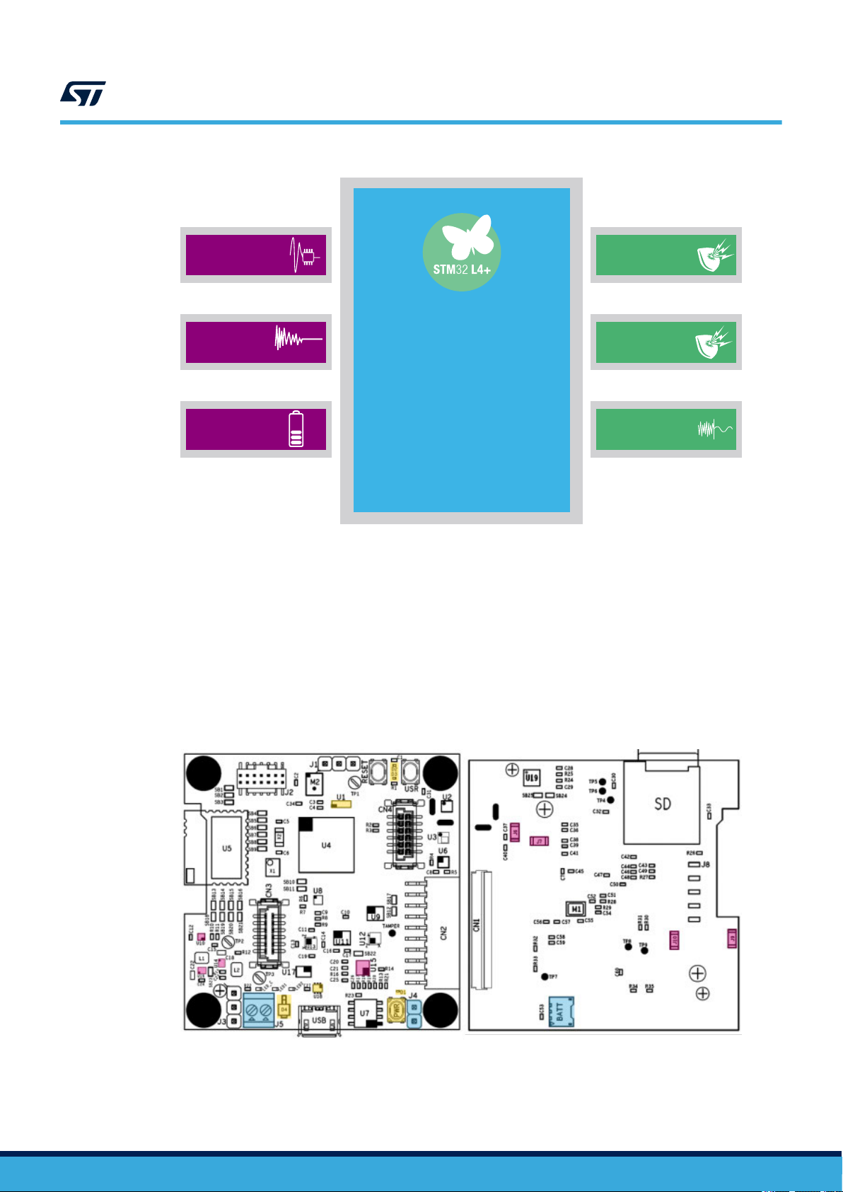
Figure 12. Power and protection components
STM32L4R9ZIJ6
Microcontroller
Ultra Low Power
Cortex M4F@120MHz
LDK130
Low Noise LDO
ESDALC6V1-1U2
Single Line ESD
protection
USBLC6-2P6
USB ESD protection
EMIF06-MSD02N16
EMI filter and ESD
protection
ST1PS01EJR
step-down
switching regulator
STBC02
Li-Ion linerar
battery charger
UM2777
Power management
Figure 13. Power and protection component locations
U1: EMIF06-MSD02N16
U10: LDK130 300 mA very low noise LDO
U14, U16: ST1PS01 400 mA Synchronous step-down converter
U15: STBC02 Li-Ion linear battery charger
U18: USBLC6-2 low capacitance ESD protection for USB
D1, D2, D3: Single-line low capacitance Transil for ESD protection
D4: Power Schottky rectifier (1A)
BATT: Battery connector
J4: Battery pins
J5: 5V Ext power supply connector
J6, J7, J9, J10: Current monitoring SMD jumper
PWR: Power button
6-line EMI filter and ESD protection for T-Flash and microSD card interfaces
UM2777 - Rev 2
page 12/45
Page 13
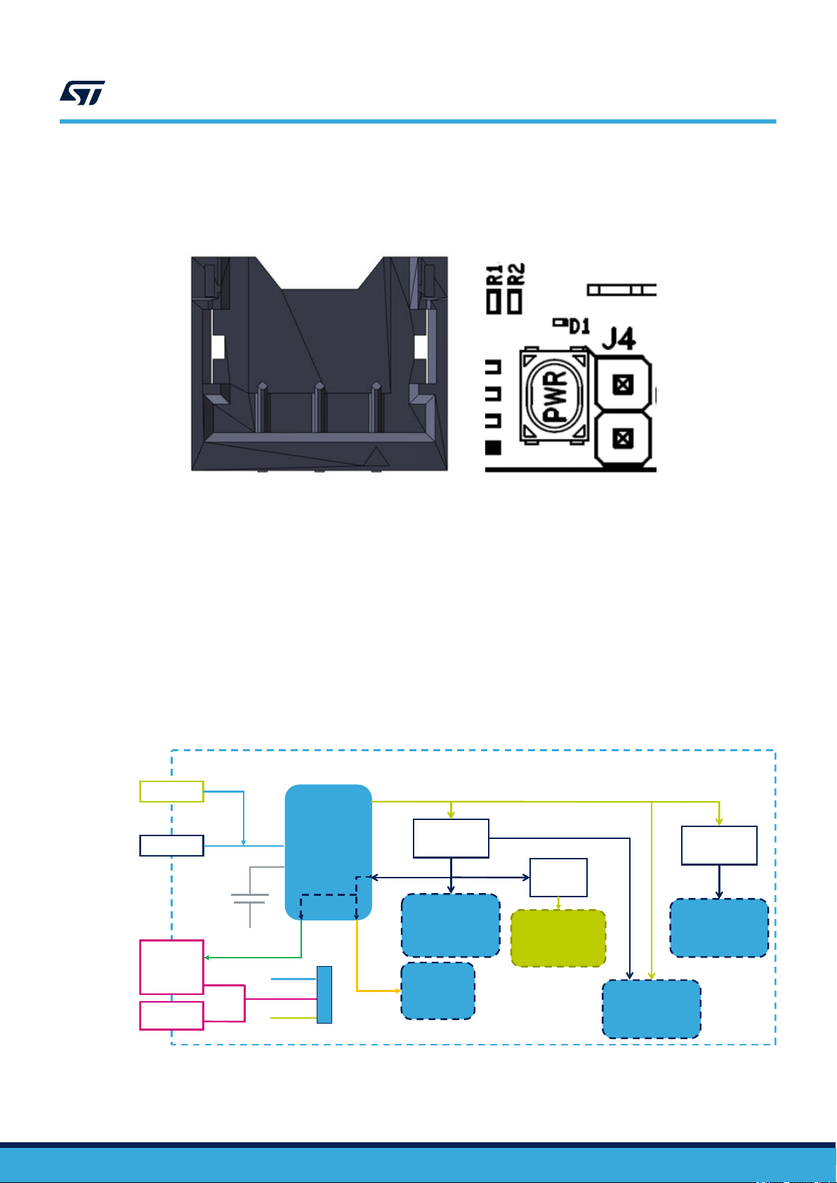
2.3.1 Battery connectors
3 2 1
2
1
VBAT
BAT_NTC
GND
VBAT
GND
STWIN core system board
USB
3V3 DCDC
U14
CN3 (Wi-Fi)
STSAFE
5V
SYS (5V or VBAT)
CN2
(AMicArray)
CN2
CN1
VBAT
J5
STBC02
Battery
Charger
Analog Mic
OpAmp
U10
2.7 LDO
DCDC_1
DCDC_2
3V3_Ext
U16
3V3 DCDC
VEXT
J3
µSDCard
RS485
SYS
V_USB
5V
STM32L4+
Sensors
Bluetooth
low
energy
The battery supply voltage (VBAT) may be provided by connecting the 480 mA LiPo battery included in the
STWIN kit to the dedicated battery connector
UM2777
Power management
, or by supplying an external voltage through the J4 connector.
Figure 14. Battery and J4 connectors for VBAT supply
2.3.2 Power supply
The STWIN core system board can receive power from different sources:
•
• Vin: through J5 connector [4.8-5.5 V]. The current on this port needs to be limited to 2 A
• VBAT: lithium ion polymer battery (3.7 V, 480 mAh), STBC02 battery charger integrated in the board
The battery is always optional. The STBC02 battery charger automatically checks the available power inputs and
selects one to power the system. When the battery is connected as well as one of the other sources, the STBC02
automatically charges the battery.
When battery-powered, the equipment is intended to work properly with an operating temperature of 35°C.
Without the battery, the equipment is intended to work properly with an operating temperature of 45°C.
V_USB: through micro USB connector [5 V]
Figure 15. Power circuits
UM2777 - Rev 2
page 13/45
Page 14
2.3.3 Power ON/OFF procedure
If the STWIN core system board is not powered via battery, then the board will turn on and off when you connect
and disconnect an external supply
, respectively.
Follow the steps below to power the board on and off when it is powered by a LiPo battery.
Step 1. Push the PWR button for about a second to power the board on.
Power on is managed by the STBC02 battery charger WAKE-UP hardware feature.
Step 2. Push the PWR button again to turn the board off.
In the application code examples provided with the software, the microcontroller detects the push
action and activates the battery charger SHUTDOWN command to switch the power supply off.
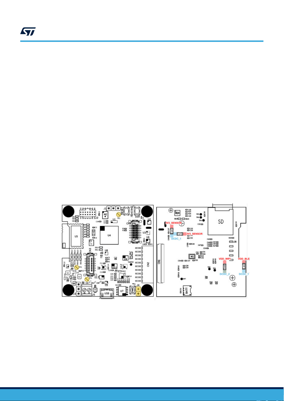
2.3.4 Power consumption evaluation
There are several test points and jumpers on the STWIN core system board available to monitor the electrical
performance of running applications. In particular
in each of the four main power supply domains on the board.
The best way to evaluate general power consumption is to remove both the battery and the USB cable and
provide 5 V directly on the J5 connector.
J6: Sensor current monitoring
J4: Battery supply
J7: STM32 digital power supply current monitoring
J9: BlueNRG-M2SA Bluetooth® low energy module current monitoring
J10: STEVAL-STWINWFV1 (Wi-Fi expansion) and STSAFE-A110 current monitoring
TP1, TP2: GND
TP3: DCDC_1 (3.3V)
UM2777
Power management
, there are four jumpers for monitoring the current consumption
Figure 16. Power monitoring points
UM2777 - Rev 2
page 14/45
Page 15

2.4 Buttons, LEDs and connectors
140
Figure 17. Buttons, LEDs and connectors
USR: User button
PWR: connected to the STBC02 for integrated W
RESET: connected to STM32 MCU reset pin (BLACK)
LED_C: Red LED connected to STBC02 and used for battery status feedback
LED1: Green LED connected to STM32
LED2: Orange LED connected to STM32
CN1: 40-pin flex general purpose expansion
CN2: STMod+ connector
CN3: 12-pin male connectivity expansion connector, suitable for the STEVAL-STWINWFV1 expansion board
CN4: 12-pin female sensor expansion connector, suitable for the STEVAL-STWINMAV1 analog microphone array expansion
board
Batt
UM2777
Buttons, LEDs and connectors
AKE-UP function and the STM32L4R9ZI MCU as generic USR button
2.4.1 Flex expansion connector
This is a general purpose expansion connector.
Pin No. Description STM32 pin Default Signal
1 USART3_CTS PB13 -
2 STMOD2 PD8/ PC3 USART3_TX/ SPI2_MOSI
3 STMOD3 PD9/ PD3 USART3_RX/ SPI2_MISO
4 STMOD4 PD1/ PB1 SPI2_CLK/ USART3_RTS
5 GND - -
6 VEXT - -
Figure 18. CN1 Flex connector top view
able 1. CN1 pin descriptions
T
UM2777 - Rev 2
page 15/45
Page 16

Pin No. Description STM32 pin Default Signal
7 I2C4_SCL PD12 -
8 SPI2_MOSI_p2 PB15 -
9 SPI2_MISO_p2 PC2 -
10 I2C4_SDA PD13 -
11 PC5/WKUP5 PC5 WKUP5
12 EX_RESET PD11 -
13 EX_ADC PA5 -
14 EX_PWM PA15 -
15 VEXT - -
16 GND - -
17 PG12 PG12 EX_CN (ex tint)
18 PG10 PG10 TIM
19 PG9 PG9 TIM
20 PB14 PB14 TIM, DSFDMD2
21 PA9 PA9 -
22 PA10 PA10 -
23 PB11 PB11 DSI_TE,TIM,LPUART_TX
24 PC13 PC13 TAMP, WKUP
25 PB9 PB9
26 PB8 PB8
27 PE9 PE9 TIM, DSFDMCLK
28 3V3_Ext - -
29 DSI_D1_N -
30 DSI_D1_P -
31 GND - -
32 DSI_D0_N -
33 DSI_D0_P -
34 SYS - -
35 DSI_CLK_N -
36 DSI_CLK_P -
37 3V3_Ext - -
38 PA0 PA0 ADC_IN5
39 PA1 PA1 ADC_IN6
40 SYS - -
CAN, TIM, DSFDM,I2C1
STM32 Display Serial Interface (DSI) Host
STM32 Display Serial Interface (DSI) Host
STM32 Display Serial Interface (DSI) Host
UM2777
Buttons, LEDs and connectors
SAI2
UM2777 - Rev 2
RELATED LINKS
View the vendor documentation on handling FH34SRJ series connectors
page 16/45
Page 17

2.4.2 STMod+ connector
UM2777
Buttons, LEDs and connectors
Figure 19. STMod+ connector top views
Daughterboard Host board
Male connector Female connector
STMod+ Pin number
10
9
8
7
6
5
4
3
2
1
20
19
18
17
16
15
14
13
12
11
PCB
Edge
Border
PCB
Edge
Border
7.62 mm2.77 mm
20
19
18
17
16
15
14
13
12
11
10
9
8
7
6
5
4
3
2
1
Table 2. STMod+ connector pin assignments and descriptions
Function1 of the primary host mapped
1
SPIx_NSS2 / UAR
2
SPIx_MOSIp3 / UART
3
SPIx_MISOp4 / UAR
T
y_CTS
y_TX Output / Output
T
y_RX Input / Input
4 SPIx_SCK / UARTy_RTS Output / Output Output / Output
5 GND Ground Reference Ground reference
6
+5 V Power Supply
5
7 I2Cz_SCL Input / Output Input / Output
8
SPIx_MOSIs3 Output
9
SPIx_MISOs4 Input / Output
10 I2Cz_SDA Input / Output Input / Output
11
INT6 Input
12 RESET Output Output
13 ADC Input Input
14 PWM Output Output
15
+5 V Power Supply
5
16 GND Ground Reference Ground reference
GPIO
GPIO
GPIO
GPIO
7
7
7
7
17
18
19
20
Output / Input
Output / Output
Input / Input
Power supply
Output
Input / Output
Input
Power supply
Output / Input
Output / Input
Output / Input
Output / Input
Description
UM2777 - Rev 2
1. If two functions are provided on a STMod+ connector pin, you can connect two different I/O ports from STM32: the firmware
manages the conflicts that may arise. MOSIs means used in Serial Daisy Chained-SPI mode and MOSIp means used in
Parallel SPI mode. More alternate functions may be available from STM32, refer to the User manual of the host board and
the corresponding STM32 datasheet available on www
.st.com.
2. Instead of SPIx_NSS, a GPIO can be used as SPI Chip Select.
3. Pins 2 and 8 are the same SPIx_MOSI signals, but they must come from two different I/O ports.
page 17/45
Page 18

4. Pins 3 and 9 are the same SPIx_MISO signals, but they must come from two different I/O ports.
b6 b1
a6 a1
b6b1
a6a1
5. Power Supply is Output or Input, depending on host / daughterboard configuration.
INT is an interrupt line.
6.
7. GPIO ports with many alternate functions (like UART, I²C, SPI and analog inputs/outputs) are privileged to offer optimum
flexibility.
RELATED LINKS
Read TN1238: STMod+ interface specification available on the ST website for more information
2.4.3 Connectivity expansion connector
Figure 20. CN3 connectivity connector top view
UM2777
Buttons, LEDs and connectors
This connector is suitable for the STEVAL-STWINWFV1 Wi-Fi expansion board.
Pin Description STM32 pin Pin Default Signal STM32 pin
a1 GND - b1 WIFI_DRDY PE11
a2 CS/USART3_CTS PB13 b2 WIFI_WAKEUP PD7
a3 SPI1_CLK/USART3_RTS PB1 b3 WIFI_BOOT0 PF12
a4 SPI1_MISO/USART3_RX PD9 b4 WIFI_RST PC6
a5 SPI1_MOSI/USART3_TX PD8 b5 I2C3_SDA PG8
a6 3V3 Output (VDD_WIFI) - b6 I2C3_SCL PG9
2.4.4 Sensor expansion connector
able 3. CN3 pin descriptions
T
Figure 21. CN4 sensor connector top view
This connector is suitable for the STEVAL-STWINMA
UM2777 - Rev 2
V1 analog microphone expansion board.
page 18/45
Page 19

Pin Description STM32 pin Pin Default Signal STM32 pin
a1 5V/Batt Output - b1 DFSDM1_D7 PB10
a2 3V3 Output - b2 DFSDM1_CKOUT PE9
a3 SAI1_FS_A - DFSDM_D3 PE4 b3 I2C2_SCL PF1
a4 GND - b4 I2C2_SDA PF0
a5 SAI1_SD_A/ SAI1_SD_B/DFSDM_D2 PE6 b5 SAI1_SCK_A PE5
a6 GND - b6 SAI1_MCLK_A/DFSDM_D5 PE2
2.5 Protective plastic box
The plastic case is designed to protect and hold the STWIN core system board and the LiPo battery together.
The case can also house two magnets (not included in the STEV
wireless industrial node on appropriate metallic areas in the monitored equipment.
RELATED LINKS
The system was tested with the following 25x8x3mm magnets
UM2777
Protective plastic box
Table 4. CN4 pin descriptions
AL-STWINKT1B kit), allowing you to stick the
2.6 STLINK-V3MINI debugger and programmer for STM32
The STLINK-V3MINI is a standalone debugging and programming mini probe for STM32 microcontrollers, with
JT
AG/SWD interfaces for communication with any STM32 microcontroller located on an application board.
It provides a Virtual COM port interface for host PCs to communication with target MCUs via UART.
The STLINK-V3MINI is supplied with an STDC14 to STDC14 flat cable.
Figure 22. STLINK-V3MINI and STDC14 cable
UM2777 - Rev 2
page 19/45
Page 20

3 How to program the board
3.1 How to program STWIN with STLINK-V3MINI
Follow the procedure below to program the STWIN core system board.
Step 1. Connect the STWIN core system board to the STLINK-V3MINI programmer using the 14-pin flat cable.
The programmer and the cable are included in the STEV
Step 2. Connect both the boards to a PC using micro USB cables.
Figure 23. STLINK-V3MINI connected to STWIN core system board
UM2777
How to program the board
AL-STWINKT1B hardware kit.
Step 3. Download the firmware onto the core system board; you can either:
–
download one of the sample application binaries provided using STM32CubeProgrammer or
ST-LINK Utility
– recompile one of the projects with your preferred IDE (EWARM, Keil, STM32CubeIDE)
3.2 How to program STWIN without STLINK-V3MINI using STM32CubeProgrammer
"USB mode"
The STEV
To enter "Firmware upgrade" mode you must follow the procedure below:
Step 1. Unplug the STWIN core system board.
Step 2. Press the USR button.
Step 3. While keeping the button pressed, connect the USB cable to the PC.
AL-STWINKT1B can also be reprogrammed via USB using the STM32CubeProgrammer "USB mode".
Now the board is in DFU mode.
UM2777 - Rev 2
page 20/45
Page 21

UM2777
How to program STWIN without STLINK-V3MINI using STM32CubeProgrammer "USB mode"
Step 4. Y
ou can upgrade the firmware by following the steps below:
Step 4a. Open STM32CubeProgrammer.
Step 4b. Select [USB] on the top-right corner.
Figure 24. STM32CubeProgrammer - USB mode selection
Step 4c. Click on
[Connect].
UM2777 - Rev 2
page 21/45
Page 22
UM2777
How to program STWIN without STLINK-V3MINI using STM32CubeProgrammer "USB mode"
Figure 25. STM32CubeProgrammer - connection
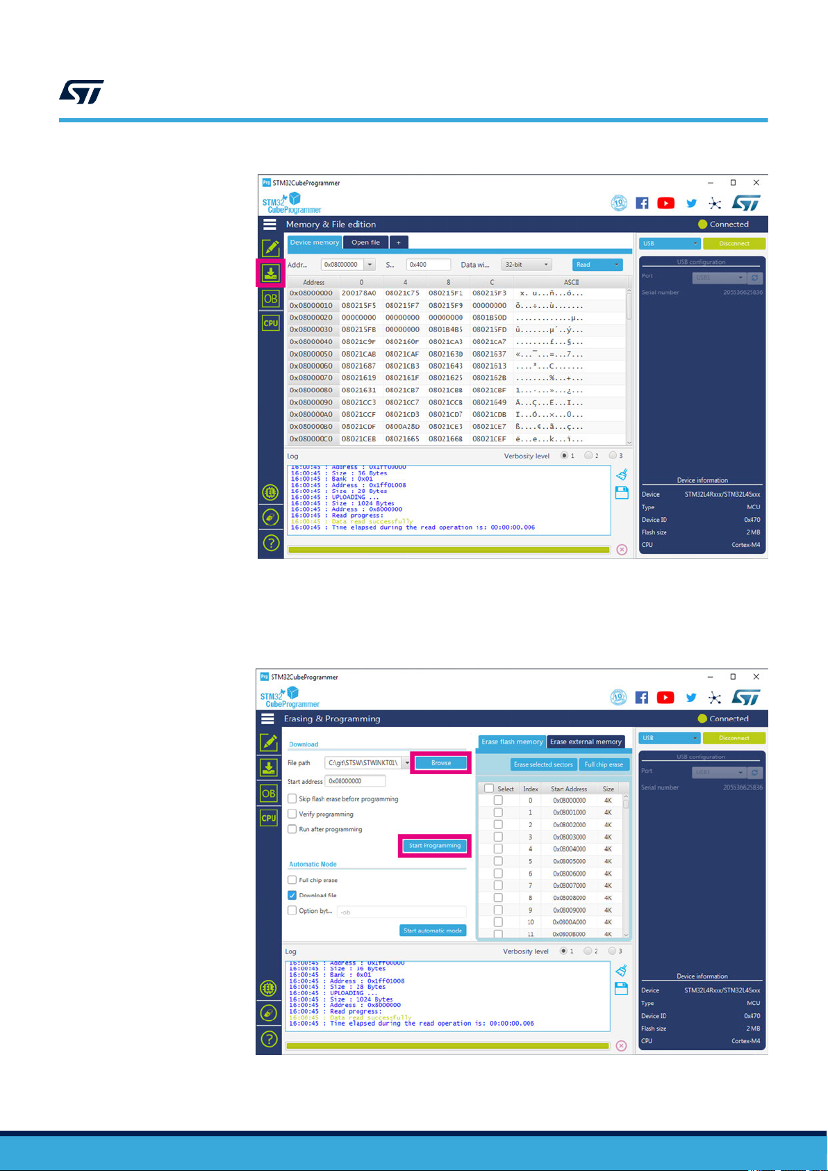
Step 4d. Go to the [Erasing & Programming] tab.
Step 4e. Search for the new .bin or .hex binary file to be flashed into the board.
Step 4f. Click on
[Start Programming].
Figure 26. STM32CubeProgrammer - programming
UM2777 - Rev 2
page 22/45
Page 23

4 STWIN assembly steps
To assemble your SensorTile Wireless Industrial Node, you need the following components:
STWIN core system board
•
• 4x M3 bolts and nuts
• Plastic box (2 parts)
• Battery
• 2x Magnets (optional - not included in the kit):
– RS Stock No. 177-4040 Brand Eclipse Mfr Part No.N859
Figure 27. Exploded cad drawing of STWIN node components
UM2777
STWIN assembly steps
UM2777 - Rev 2
page 23/45
Page 24
STWIN assembly steps
Step 1. (Optional) Insert the magnets in the rectangular recesses in the bottom of the main case.
Figure 28. Optional magnets inserted in main case
UM2777
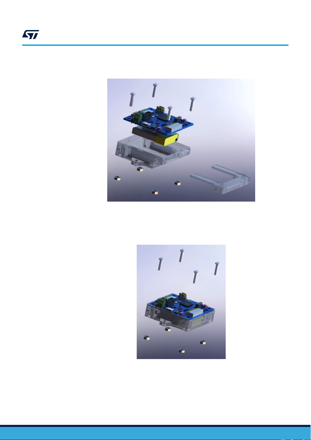
Step 2. Slide the U-shaped bracket into the main case.
This will secure the magnets if they are present.
Step 3. Insert the STWIN core system board with the correct orientation.
Figure 29. Core system board inserted in main case
UM2777 - Rev 2
page 24/45
Page 25
STWIN assembly steps
Step 4. Fasten the core system board to the case using the nuts and bolts provided with the kit.
Figure 30. Core system board fastened with bolts
UM2777
UM2777 - Rev 2
page 25/45
Page 26
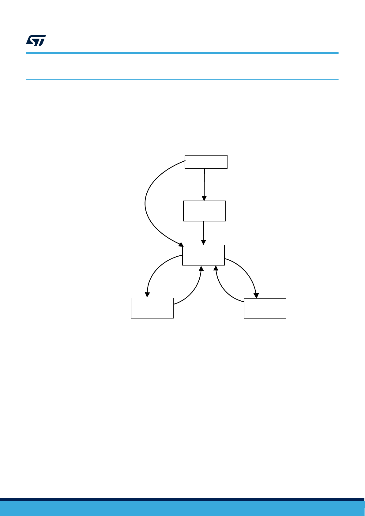
5 How to run the HSDatalog application
IDLE
SDCard inserted and
JSON config found
USB cmd
START
POWER ON
LOAD CUSTOM
CONFIG
LOG TO
SDCARD
LOG VIA USB
USB cmd
STOP
NO SD Card or
JSON config
not found
USER Button or
BLE Command
Bluetooth low energy
UM2777
How to run the HSDatalog application
The HSDatalog (High-Speed Datalog) application is part of the FP-SNS-DA
TALOG1 STM32ODE function pack.
It allows you to save data from any combination of sensors and microphones configured up to their maximum
sampling rate. Sensor data are stored on a micro SD Card, SDHC (Secure Digital High Capacity) formatted with
the FAT32 file system, or can be streamed to a PC via USB.
At startup, the application tries to load the device configuration from the SD card (if any) and then goes to Idle
state, waiting for the start command either via USB, push button or Bluetooth® low energy.
Figure 31. HSDatalog data flow
UM2777 - Rev 2
Together with HSDatalog application, inside the Utilities folder, MATLAB and Python scripts are available to
automatically read and plot the data saved by the application.
The script has been successfully tested with MA
The 'ReadSensorDataApp.mlapp' MATLAB app is also available, developed and tested using the App Designer
tool available in MATLAB v2019a.
TLAB v2019a and Python 3.7.
page 26/45
Page 27

Figure 32. Folder structure in the SD card
UM2777
How to run the HSDatalog application
The script performs the following actions:
•
Reads and decodes the JSON file
• Reads the raw data and uses the information from the JSON to translate them into readable data (data +
timestamp)
• Plots the data
Note: The handling of JSON scripts requires MATLAB v2019a or above.
UM2777 - Rev 2
page 27/45
Page 28

2.7 V Analog LDO
5
V_USB
SW_SEL
ESDALC6V1-1U2
C22
TP2
EN
SH1
10uF
CON2
1
EN
B2
U16
DCDC_1
SH2
OTG_FS_DP
DCDC_1
R12
VBat
B4
AGND
IN2
F5
TH
1
R13
USB-MICRO
3
SW1_OA
100k
R15 1M
E3
VOUT
D1
1
OUT
C23
3V3_LDO
20K
NC2
D3
A3
E1
TH
1
OTG_FS_DM
F4
C4
BATMS
C2
USB
CHG
E1C5
SYS1
LDK130PU-R
6
IN
IN1
E5
3V3 15 0mA.
SW2_I
F2
E4
4
EN
5V
4
DCDC_1
C_EN
3V3_SD_485
R23
BAT_NTC
F3
SW1_I
VIN
BAT_NTC
47.5K
4.7uF
2k
TH
1
SYS
3
D2
CHRG
RESET_NOW
CEN
B1
C1
VIN
STBC02AJR
LDO
3
EXT 5V
3.3V DC-DC
NC
C3
V_USB
5V
100k
A4
ISET
D4
IPRE
SYS
56K
22uF
DCDC_1
ADJ
A3
R11
RST_PENDING
A1
2k
VOUT
D1
U18
3V3_Ext
SW_SEL
R17
6
D4
PWR
1
E1
PGOOD
GND
D2
Battery Connector
A1
D0
NC
5
Battery management
DCDC_2_EN
3V3 400 mA
3V3 40 0mA.
(4.2 V -> 3 V)
Battery monitor
3
R22
C15
VBat
BUTTON_PWR
20K
C27
SW2_OA
F1
D4
2
DCDC_1
L2 2.2uH
A1
D0
C1
B2
R21 0R
VBUS
4
D3
C21 10uF
R10
BAT2
B5
D5
SYS2
R20
C20 1uF
NCSB17
100k
J5
SB23 0R
TP7
C1
1
1
5
SB22
2
C25 10uF
R16
C12
10uF
C18
VBat
D1
ST1PS01EJR
SW
SW2_OB
SW_SEL
uC_ADC_BATT
SB12 0R
DCDC_2
USBLC6-2P6
2
GND
GND
A3
1uF
PGOOD
LED_C
Red
2
C3
2
2
1
DCDC_2
R18
1
J4
2
STRIP254P-M-2
U10
DCDC_1
BUTTON_PWR
TP3
VBat
E3
SW1_OB
C3
E3
nRESET
E2
100mA 10mA
TP1
R19 0R
U15
2V7A
PGOOD
GND
D2
22uF
R14
B2
ST1PS01EJR
SW
D1
1
3
100nF
1
2
C24
BATT
L1 2.2uH
NC
4
2
BAT1
A5
A2
2
GND
SYS
D2
WAKEUP
100K
U14
1uF
V_USB
BATMS
NC (10k )
BATMS
B3
BATSNS
NTC
D1
DCDC_1
1
C26
BATSNSFV
UM2777 - Rev 2
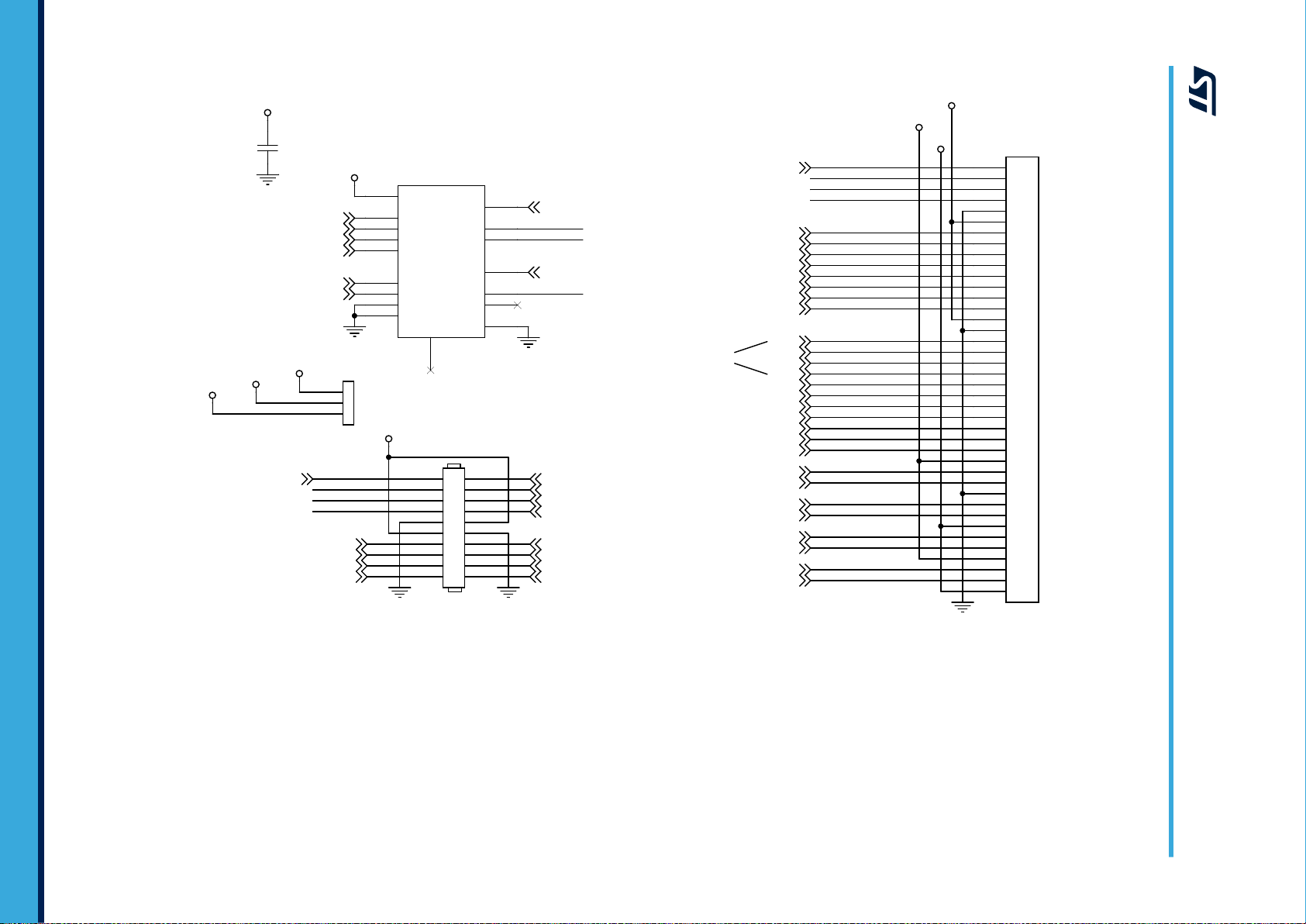
6 Schematic diagrams
page 28/45
Figure 33. STEV
AL-STWINKT1B schematic (1 of 7)
Schematic diagrams
UM2777
Page 29
NC
10
STMOD4
SPI2_MISO_p2
3
4S1
3-4SEL
40
8
16
DSI_D1_N
20
18
21
EX_RESET
7
7
PC5/WKUP5
13
2
12
19
PG10
PB14
3-4SEL
15
17
EX_PWM
SYS
PG10
17
3V3_Ext
10
PG12
USART3_RTS
10
3
DSI_CLK_N
D3
PG9
18
1
PB11
16
29
VEXT
26
SPI2_MOSI
15
PA9
PB9
USART3_CTS
9
20
C60
100nF
31
STMOD2
I2C4_SCL
4
CN1
FH34SRJ-40S-0.5SH(99)
1-2SEL
13
PA0
3
PG9
DSI_D0_P
25
3
DSI_D1_P
USART3_CTS
1S1
12
STMOD2
5
30
8
U17
STG3692
19
1
I2C4_SDA
GND
VEXT
32
SPI2_MISO
SYS
STMOD2
14
1-2SEL
4S2
14
SPI2_CLK
STMOD4
7
USART1
WKUP5
TIM, DSFDMCLK
TIM
TAMP, WKUP
DSI_TE,TIM,LPUART_TX
DCDC_1
4
11
2S1
VCC
I2C4_SDA
2
33
2
EX_PWM
17
4
11
27
STMOD3
DSI_D0_N
1
STMOD3
9
PA1
SPI2_MISO_p2
35
38
2S2
6
14
I2C4_SCL
34
PC5/WKUP5
5V
24
STMod+ interface
PE9
6
SPI2_MOSI_p2
PB8
9
2
28
PG12
1
EX_RESET
36
D2
1S2
13
PB14
16
J3
CN2
PA10
6
39
VEXT
3S1
23
5
PC13
3S2
STMOD4
D1
USART3_RX
5
STMOD3
37
SPI2_MOSI_p2
EX_ADC
15
EX_ADC
SAI2
CAN, TIM, DSFDM,I2C1
TIM,DSFDMD2
TIM
ADC_IN5
ADC_IN6
EX_CN
USART3_TX
22
11
8
DSI_CLK_P
DCDC_1
12
D4
UM2777 - Rev 2
Figure 34. STEV
AL-STWINKT1B schematic (2 of 7)
page 29/45
Schematic diagrams
UM2777
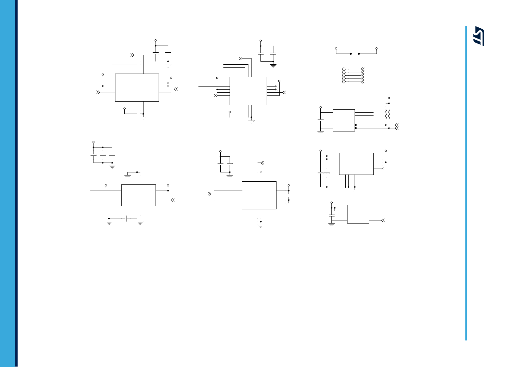
Page 30
INT2_DH
I2C2_SDA
CS
VDD
SCL/SPC
C13
100nF
INT1
3V3_Sensors
4
C14
100nF
SPI3_MISO
OCS_Aux
VDD
R4
7.5k
C1
9
14
2
CS
2
SPI3_MISO
8
5
5
SDO_Aux
1
OCS_Aux
SCL
6
RES
12
C8
100nF
6
3
SDA
5
INT2_DHC
1
INT2_ADWB
TP4
U9
ISM330DHCX
SPI3_CLK
GND1
NC1
11
C58
10uF
8
GND2
SCx
3
CS
VDD
CS
13
VDD
INT
3V3_Sensors
7
I2C2_SCL
C31
100nF
5
4
10
4
SDO/SA0
I2C2_SCL
GND
INT1
GND
5
U6
SDO/SA0
U2HTS221
INT2
SPI3_MOSI
9
C56
100nF
3
9
I2C2_SCL
3
12
3V3_Sensors
4
C17
100nF
I2C2_SDA
SCL
3
3V3_Sensors
8
3V3_Sensors
SPI3_MOSI
TP6
10
C40
100nF
1
C57
100nF
SDA
U3
LPS22HH
3
6
DRDY
5
11
I2C2_SDA
3V3_Sensors
GND2
5
SCx
3V3_Sensors
2
INT1
R5
7.5k
SPI3_CLK
U12
TP8
3V3_Sensors
9
CS_DH
SPI3_MOSI
CS_ADWB
SCL
SDO/SA0
J6
Sensors and digital mic current monitoring
13
4
12
SPI3_CLK
7
VDDIO
CS
INT_DRDY
6-Axis
Acc + Gyro
Pressure
SPI3_MISO
INT1_ADWB
SDO_Aux
3V3_Sensors
2
8
6
14
SDA
3V3_Sensors
GND2
1
4
7
TP5
SDA/SDI/SDO
C11
10uF
SCL/SPC
SDO/SA0
1
9
10
SPI3_CLK
1
U11
SPI3_MOSI
1
INT_HTS
2
2
I2C2_SMBA
6
SDA/I/O
I2C2_SCL
VDD
VDDIO
3V3_Sensors
VDDIO
SDA/I/O
12
I2C2_SDA
3V3_Sensors
CS
7
6
I2C Addr: 1001000b
I2C Addr: 0011110b
I2C Addr: 1011111b
I2C Addr: 1011101b
8
3V3_Sensors
GND1
EV
11
SCL
INT_M
7
10
INT2
VDDIO
C19
0.22uF
C59
100nF
SPI3_MISO
3V3_Sensors
10
GND
GND3
NC2
Therm
2
INT2
3V3_Sensors
3V3_Sensors
1
SDA
Magnetometer
Vibrometer
Humidity & Temperature
U13IIS2MDC
3V3_Sensors
GND1
VDD
NC3
3V3_Sensors
2
C37
4.7uF
C16
100nF
3
VDD
INT1_DHC
6
I2C2_SCL
INT_STT
CS_DHC
DCDC_1
SDx
SCL
4
GND2
I2C2_SDA
SDx
TP9
VDD_IO
GND
RES
3V3_Sensors
11
GND2
Accelerometer
Temperature
IIS3DWB
STTS751
IIS2DH
UM2777 - Rev 2
Figure 35. STEV
AL-STWINKT1B schematic (3 of 7)
page 30/45
Schematic diagrams
UM2777
Page 31

U4
X1
16MHz
STM32L4R9ZIJ6
CS_WIFI
I2C3_SDA
2
F10
J1
G5
M6
SAI1_MCLK_A
PF12
PB1
C6
VDDUSB
A9
C11
R3
4.7k
PH1-OSC_OUT
INT1_DHC
H9
G3
PGOOD
WIFI_BOOT0
L6
PD15
SWDIO
R34
1k
G7
D2
ESDALC6V1-1U2
RESET
PF0
BOOT0-PE0
E9
PA0
PB10
F7
K8
PC0
C1
VDD_uC
VSS4
SPI1_MOSI
1
J9
PB11
B2
K9
LED2
SDMMC_D3
10
2
PA10
C49
6.8pF
OSC32_OUT
PA9
PG5
PF2
PG9
INT1_ADWB
E11
PG10
PG7
C45
100nF
LED2
Orange
R2
4.7k
INT_M
Differential pairs
100 OHM
R32
4.7k
D3
ESDALC6V1-1U2
LED2
SPI3_MISO
B1
EX_PWM
PA10
I2C2_SMBA
VBATVSSDSI
CHRG
R33
4.7k
INT_STT
CS_ADWB
D4
VDDA
C5
5.6pF
PC14-OSC32_IN
D1
H6
PF15
SPI2_MISO
WIFI_DRDY
B8
PD12
I2C4_SDA
PF7
PA15
SDMMC_D1
H10
L2
PD3
PA1
PE2
A8
C3
VDD_uC
PD7
PB9
PD9
7
PC13
VDD5
J2
PE11
PC1
L11
USART2_TX
BOOT0-PE0
PC9
PA14/SWCLK
C12
PD8
SPI2_MOSI_p2
H7B12
PB8
PE3
M10
PA5
L4
C48
1uF
RESET
OSC32_OUT
STSAFE_RESET
VDD1
C35
100nF
PB14
R35
560R
PC2
PD14
I2C4_SCL
DSI_D0_P
G12
VDD4
PF5
1
2
USART3_RTS
DAC1_OUT1
DFSDM1_CKOUT
5
H12
PD0
M3
E2
PE15
PF1
PF14
PC11
PE5
PG10
E3
C41
4.7uF
SWDCLK
PD6
INT2_ADWB
G8
PA0/WKUP1
PF6
USART2_TX
SDMMC_D0
K3
PA8
F11
D11
VSS5
E12
NRST
H3
4
PB5
PB3
PC4
G4
4
L5
VDD2
PB12
A10
USART2_RX
PG3
PA6
K10
OSC_IN
11
C39
100nF
J12
PB14
VREF+
C10
D12
PC6
OSC32_IN
PA11
INT2_DHC
E1
A6
M8
VDDIO2_1
PG1
USART3_TX
4
A11
VSS3
INT2_DH
DSI_CLK_N
K12
PG6
PE7
G6
E4
DFSDM1_D7
F9
3
1
SAI1_SD_B
BUTTON_PWR
M7
WIFI_WAKEUP
1
PE14
SDMMC_CK
G9
C7
SAI1_SD_A
PD4
PE8
CS_DH
PB2
2V7A
H5
DSIHOST_D0P
SPI1_CLK
PG2
PE4
D3
J10
SD_DETECT
PC8
PD1
PC10
B7
E10
I2C4_SCL
8
BOOT0-PE0
D8
SPI3_MOSI
D5
B3
I2C2_SCL
SWDCLK
PE13
PF9
OSC32_IN
K5
K1
J4
12
A7
H4
BLE_RST
USART3_RX
B10
VDD6
D6
F4
VDD_uC
PG12
1
INT_HTS
DSIHOST_D1P
RTC_TAMP1
H11
PA3
SAI1_FS_A/DFSDM_D3
B9
J6
C2
C9
uC_ADC_BATT
PG8
DSI_D1_N
SPI2_CLK
PB6
VSS6
G11
2
G2
ADC1_IN2
PA4
VSS9
J7
STM32 Current monitoring
PA1
M4
K4
A5
B4
F12
PB4
SPI1_MISO
2
VDD_uC
PE12
R1
10k
C4
PD10
PC3
H8
14
OSC_OUT
PB15
6
9
A12
PE10
PG0
M5
D7
PF3
VDDIO2_2
H1
I2C2_SDA
E5
PH0-OSC_IN
1
OSC_OUT
I2C3_SCL
PC5/WKUP5
USART3_CTS
PH3-BOOT0
A4
L12
I2C2_SDA
L10
PF10
I2C4_SDA
C38
100nF
C1
100nF
DSIHOST_D0N
PA13/SWDIO
EX_ADC
PC13/WKUP2
3-4SEL
1
C6
5.6pF
SPI2_MOSI
EX_RESET
BLE_SPI_CS
DSI_D0_N
PD13
DSIHOST_D1N
DSIHOST_CKP
H2
G10
SDMMC_D2
3
PF13
K7
PG13
OTG_FS_DM
K11
K2
2V7A
PC12
PE12
D9
J11
BLE_TEST9
PG12
C50
100nF
E8
LED1
D10
A1
PB0
VSS1
USART2_RTS
2
C46
10nF
L9
PB7
PC7
PD2
B6
VDD_uC
C43
6.8pF
RESET
J8
PF8
VDD3
F1
G1
PC5/WKUP5
C42
100nF
C32
100nF
SW_SEL
PA9
A2
1
13
PE0
D2
VSS2
PC15-OSC32_OUT
DCDC_2_EN
C_EN
M1
F2
2
E6
2
2
VDD_uC
PB11
AGND
EXTI_LINES
EXTI0 --> USR Button
EXTI1 --> BLE
EXTI2 --> INT2_DH or INT2_ADWB
EXTI3 --> BLE_TEST9
EXTI4 --> INT2_DHC
EXTI5 --> WKUP_INT
EXTI6 --> HTS
EXTI7 --> PGOOD
EXTI8 --> INT1_DLC
EXTI9 --> Mag
EXTI10 --> PWR_BTN
EXTI11 --> WiFi
EXTI12 --> EX_CN
EXTI13 --> TAMP,WKUP Ext
EXTI14 --> INT1_ADWB
EXTI15 --> INT_STT
USR/BOOT
VCAPDSI
BLE_TEST8
ADC1_IN1
PB8
RESET
1-2SEL
VDD7
PG4
K6
DSI_CLK_P
PF11
VDD_uC
PE6/WKUP3
F5
PG9
VSS8
1
USART2_RX
PA2/WKUP4
B5
CHRG
LED1
Green
SDMMC_CMD
J7
M12
PA7
J2
STDC14
PE9
M9
SAI1_SCK_A
DSIHOST_CKN
A3
PB9
M2
DCDC_1
3
WIFI_RST
E7
J3
C8
PE1
OTG_FS_DP
LED1
C34
100nF
L3
X2
32.7680KHZ
SP1
L8
PD11
VSS7
C5
SPI3_CLK
PD5
OSC_IN
F6
B11
M11
I2C2_SCL
PF4
CS_DHC
PE9
Close to
VREF/VDDA
Close to VDD/VDDIO2
Close to
VDDUSB
SWDIO
BLE_INT
C44
100nF
PA12
J5
L7
PB13
DSI_D1_P
C7
2.2uF
VSSA/VREF-
C36
1uF
L1
F3
USR
3
4
DFSDM1_DATIN5
C47
100nF
SPI2_MISO_p2
F8
UM2777 - Rev 2
Figure 36. STEV
AL-STWINKT1B schematic (4 of 7)
page 31/45
Schematic diagrams
UM2777
Page 32

AudioCoupon Connector
HP Filter --> fc = 15.9 Hz
LP Filter --> fc = 99.4 KHz
DAC for mic bias
DFSDM_D2
DFSDM_D5
DCDC_1
3V3_Sensors
2V7A
2V7A
2V7A
SYS
DFSDM1_DATIN5
DFSDM1_CKOUT
DFSDM1_CKOUT
DFSDM1_D7
SAI1_FS_A/DFSDM_D3
SAI1_MCLK_A
SAI1_SD_A SAI1_SCK_A
I2C2_SDA
I2C2_SCL
SAI1_SD_B
DAC1_OUT1
ADC1_IN2
ADC1_IN1
PE12
R74.7k
C2
100nF
C51
100nF
R8
1M
CN4
M55-6001242R
a1 b1
a2 b2
a3 b3
a4 b4
a5 b5
a6 b6
C9
10nF
U8
TS922EIJT
Vcc-
C2
+IN2
C3
OUT2
A3
-IN2
B3
Vcc+
A2
OUT1
A1
-IN1
B1
+IN1
C1
C54
10nF
C55
1uF
R28
10k
M1
DOUT
1
GND12GND2
3
VDD
5
GND3
4
SB110R
C10
100nF
C52
1uF
M2
DOUT
4
LR2GND
5A
VDD
1
CLK
3
GND5BGND5DGND
5C
R6100k
R9
1M
SB10NC
R29160
C30
1uF
MREF
M1
M1P_FILT
M1P_FILT
MREF
M1P
MREF_DIV
MREF
RE
CLK_Ex
EP
11
2
10A
SDMMC_D2
CMD
USART2_RTS
3
SB25 0R
11
U1 EMIF06-MSD02N16
4
RDAT3_GND
DETGNDA
SDMMC_CMD
17
10
C29
10nF
7
DAT0_Ex
SD
Micro-SD
6
CLK_In
3V3_SD_485
SDMMC_D0
9A
SDMMC_D1
15
VCC
SDMMC_D3
VCC
1 10
C3
100nF
USART2_TX
VDD
14
GND
DAT2_Ex
1
6
DAT1
DAT2_In
3
GND
SD Card
RS485
SB24 NC
Card Removed --> CLOSE
Card Inserted --> OPEN
DETGNDB
5
9B
3
DE
B
CD/DAT3
DAT2
J1
NC
1
5
CMD_In
DAT1_Ex
6
3V3_SD_485
SD_DETECT
C28
100nF
SD_DETECT
CLK
9
4
2
DAT3_In
GND
DAT0
8
R24 62
DETCA
2
C4
10uF
5
DETCB
8
13
12
4
DAT1_In
VL
RDATA_VCC
CMD_Ex
7
16
R
U19 STR485LV
R25 62
SLR
10B
3
D
USART2_RX
DAT0_In
DAT3_Ex
1
9
WP/CD
8
A
7
SDMMC_CK
2
3V3_SD_4853V3_SD_485
IMP34DT05
MP23ABS1
UM2777 - Rev 2
Figure 37. STEV
AL-STWINKT1B schematic (5 of 7)
page 32/45
Schematic diagrams
UM2777
Page 33

A
8
DAT0_In
14
7
SLR
2
DETGNDB
VDD
4
10B
SB25
12
CMD_Ex
13
6
GND
STR485LV
DAT2
6
GND
10
B
9
8
NC
1
3V3_SD_485
Micro-SD
3
DAT2_Ex
VCC
15
3V3_SD_485
RE
4
10nF
U1
DAT2_In
2
100nF
WP/CD
8
3V3_SD_485
Card Removed --> CLOSE
Card Inserted --> OPEN
SDMMC_D2
SDMMC_CK
DAT3_Ex
7
C28
USART2_TX
C29
6
SD_DETECT
C3
SD Card
RS485
DE
3
CMD_In
4
R
2
0R
SDMMC_D1
DETGNDA
DETCA
9A
CLK
5
100nF
R24 62
DAT1_In
9
CD/DAT3
1
U19
17
11
CLK_Ex
D
5
11
VCC
9B
10uF
3V3_SD_485
EP
62
2
SDMMC_D0
DAT17DAT0
SDMMC_D3
SDMMC_CMD
VL
1
RDAT3_GND
1
DAT0_Ex
GND
CLK_In
EMIF06-MSD02N16
5
3
CMD
C4
J1
DETCB
10A
16
RDATA_VCC
DAT1_Ex
10
R25
USART2_RTS
SD_DETECT
USART2_RX
NCSB24
DAT3_In
3
SD
UM2777 - Rev 2
Figure 38. STEV
AL-STWINKT1B schematic (6 of 7)
page 33/45
Schematic diagrams
UM2777
Page 34

9
b1
b3
I2C3_SDA
CS_WIFI
BLE_SWDCLK
BLE_CS
100nF
5
SDA
1
1
4.7k
5
SPI1_CLK
18
DIO1/SPI_CS
2
SPI1_MISO
a4
Male Conn
NCSB15
BLE Current monitoring
R30
USART3_RTS
19
8
SPI1_MOSI
BLE_RST
1
BLE_SPI_MISO
RTC_TAMP1
DCDC_2
VDD_BLE
4
U5
USART3_CTS
47k
BLE_SWDCLK
100nF
SB13 NC
21
NC#21
NC#3
7
SCL
4.7k
b6
SB4
NCSB16
a3
SO8N
DIO3/SPI_MOSI
SB9 NC
BT_RESET
20
4
GND
R31
VDD_BLE
WIFI_WAKEUP
14
VDD_WIFI
RESET
VCC
2
BLE_SWDIO
WIFI_BOOT0
ADC IN2
BLE_INT
SB21 0R
0RSB18
3
SB20 0R
BLE_TEST8
ADC IN1
1
STSAFE-A110
8
0R
DIOA12
USART3_TX
13
3
NC#1
NC
SPI2_MOSI
NC
SPI1_MOSI
STRIP254P-M-5-90-SMD
SB6 0R
WIFI_DRDY
SPI1_MISO
C33
USART3_RX
BLE_SWDIO
SB3 NC
15
1
Default ON
Default OFF
Default ON
Default OFF
M55-7001242R
BLE_SPI_MOSI
SPI2_MISO
BLE_SPI_SCK
VDD_WIFI
SB8 0R
5
DIO4/I2C_CLK
2
a2 b2
USART2_TX
R27
2
DIO0/SPI_CLK
16
I2C3_SCL
DIO14/ANATEST0
DIO7/BOOT/UART_CTS
GND
DIO6/UART_RTS
DIO8/UART_TXD
DIO11/UART_RXD
DIO9/TCK/SWTCK
DIO10/TMS/SWTDI
ANATEST1
6
NC#2
I2C3_SCL
I2C3_SCL
VBLUE
4 17
BLE_TEST9
DCDC_2
WIFI_RST
I2C3_SDA
J8
NCSB14
Wi-Fi Current monitoring
SB5 0R
10
BLE_SPI_MOSI
I2C3_SDA
SB2
SB7 NC
SPI1_CLK
a1
4.7k
R26
b4
a5
DCDC_2
DCDC_1
U7
11
12
SPI2_CLK
DIO5/I2C_SDA
3
C53
BLE
WIFI
STSAFE-A100
TAMPER
SB1
BLE_INT
a6
STSAFE_RESET
J10
BLE_SPI_MISO
7
USART2_RX
NC#22
22
CN3
VDD_BLE
VDD_BLE
BLE_SPI_SCK
b5
BLE_SPI_CS
SB19 0R
23
NC#23
BlueNRG-M2SA
DIO2/SPI_MISO
6
BLE_RST
J9
BLE_CS
2
UM2777 - Rev 2
Figure 39. STEV
AL-STWINKT1B schematic (7 of 7)
page 34/45
Schematic diagrams
UM2777
Page 35

7 Bill of materials
Table 5. Bill of materials
Item Q.ty Ref. Part / Value Description Manufacturer Order code
1 1 BATT
2 1 CN1 Hirose FH34SRJ-40S-0.5SH(99)
3 1 CN2 HEADER 10 Samtec SQT-110-01-F-D-RA
4 1 CN3
5 1 CN4
C1, C2, C3, C8,
C10, C13, C14,
C16, C17, C27,
C28, C31, C32,
6 30
7 7
8 2 C5, C6 5.6pF, 10V, ±1%
9 1 C7 2.2µF, 10V, ±20%
10 4 C9, C29, C46, C54 10nF, 25V, ±10%
11 8
12 2 C18, C22 22µF, 10V, ±20%
13 1 C19 0.22µF, 16V, ±10%
14 3 C26, C37, C41 4.7µF, 10V, ±20%
15 2 C43, C49 6.8pF, 10V, ±5%
16 3 D1, D2, D3
17 1 D4 1A
C33, C34, C35,
C38, C39, C40,
C42, C44, C45,
C47, C50, C51,
C53, C56, C57,
C59, C60
C4, C11, C21,
C23, C24, C25,
C58
C12, C15, C20,
C30, C36, C48,
C52, C55
100nF, 16V, ±10%
10µF, 10V, ±20%
1µF, 10V, ±10%
Battery Connector
Amass
M55 series 12 pin
connector
M55 series 12 pin
connector - Female,
1.27pitch
CAP CER X7R 0402,
0402 (1005 Metric)
CAP CER X5R 0402,
0402 (1005 Metric)
CAP CER C0G/NP0
0402, 0402 (1005
Metric)
CAP CER X5R 0402,
0402 (1005 Metric)
CAP CER X7R 0402,
0402 (1005 Metric)
CAP CER X5R 0402,
0402 (1005 Metric)
CAP CER X5R 0603,
0603 (1608 Metric)
CAP CER X7R 0402,
0402 (1005 Metric)
CAP CER X5R 0402,
0402 (1005 Metric)
CAP CER C0G/NP0
0402, 0402 (1005
Metric)
Single-line low
capacitance T
for ESD protection,
ST0201
Power Schottky
rectifier
, 1.27pitch
ransil™
, STmite
Molex 78171-0003
Harwin M55-7001242R
Harwin M55-6001242R
Murata
Electronics North
America
Samsung ElectroMechanics
America, Inc.
Yageo CC0402BRNPO9BN5R6
Wurth Electronics
Inc.
AVX Corporation 04023C103KAT2A
Taiyo Yuden JMK105BJ105KV-F
Taiyo Yuden LMK107BBJ226MA-T
Murata
Electronics North
America
Murata
Electronics North
America
Murata
Electronics North
America
ST ESDALC6V1-1U2
ST STPS120M
GRM155R71C104KA88J
CL05A106MP8NUB8
Wurth-885012105013
GRM155R71C224KA12D
GRM155R61A475MEAAD
GRM0225C1E6R8CA03L
UM2777
Bill of materials
UM2777 - Rev 2
page 35/45
Page 36
Bill of materials
Item Q.ty Ref. Part / Value Description Manufacturer Order code
18 1 J1 N.M.
19 1 J2 STDC14
20 1 J3 CON5_1 V_EXT selector - -
21 1 J4 STRIP254P-M-2 - -
22 1 J5 CON2
23 1 J6
24 1 J7
25 1 J8 N.M.
0 OHM 1206 or
2.54 Jumper
0 OHM 1206 or
2.54 Jumper
Stripline for RS485 (not
mounted)
STDC14 - ARM MIPI10
compatible
Morsettiera a 2 vie,
passo 2.54mm
Sensors and digital
mic current monitoring:
RES SMD
STM32 Current
monitoring: RES SMD
STRIP254P-M-5-90SMD (not mounted)
- -
Samtec FTSH-107-01-L-DV-K
- -
Yageo AF1206JR-070RL
Yageo AF1206JR-070RL
- -
UM2777
26 1 J9
27 1 J10
28 1 LED_C Red LED, LED_0402
29 1 LED1 Green LED, LED_0402
30 1 LED2 Orange LED, LED_0402
31 2 L1, L2 2.2uH, ±20% Inductor, 2520 Wurth Wurth-74438323022
32 1 M1 1.3A MEMS audio sensor ST IMP23ABSU
33 1 M2 MEMS audio sensor ST IMP34DT05
34 2 USR, PWR
35 1 RESET
36 1 R1
37 8
38 2 R4, R5
39 4 R6, R12, R14, R20
40 3 R8, R9, R15
41 1 R10
42 2 R11, R16
R2, R3, R7, R26,
R30, R31, R32,
R33
0 OHM 1206 or
2.54 Jumper
0 OHM 1206 or
2.54 Jumper
4.2x3.2x2.5mm,
white
4.2x3.2x2.5mm,
black
10k, 100ppm/C,
1/16W
, ±1%
4.7k, 100ppm/C,
1/16W
, ±1%
7.5k, 100ppm/C,
1/16W
, ±5%
100k, 100ppm/C,
1/16W
, ±1%
1M, 100ppm/C,
±1%
47.5K, 100ppm/C,
1/16W
, ±1%
20K, 100ppm/C,
1/16W
, ±1%
Bluetooth® low energy
current monitoring:
RES SMD
Wi-Fi Current
monitoring: RES SMD
SW PUSHBUTTONSPST
-2
SW PUSHBUTTONSPST
-2
RES SMD 0402, 0402
(1005 Metric)
RES SMD 0402, 0402
(1005 Metric)
RES SMD 0402, 0402
(1005 Metric)
RES SMD 0402, 0402
(1005 Metric)
RES SMD 0402, 0402
(1005 Metric)
RES SMD 0402, 0402
(1005 Metric)
RES SMD 0402, 0402
(1005 Metric)
Yageo AF1206JR-070RL
Yageo AF1206JR-070RL
Vishay
Semiconductor
Opto Division
Panasonic
Electronic
Components
Panasonic
Electronic
Components
ALPS SKRPABE010
ALPS SKRPADE010
Yageo RC0402FR-0710KL
TE Connectivity
Passive Product
Yageo RC0402JR-077K5L
TE Connectivity
Passive Product
TE
CONNECTIVITY
Yageo RC0402FR-0747K5L
Yageo RC0402FR-0720KL
VLMS1500-GS08
LNJ347W83RA
LNJ847W86RA
CRG0402F4K7
CRG0402F100K
CRG0402F1M0
UM2777 - Rev 2
page 36/45
Page 37

Bill of materials
Item Q.ty Ref. Part / Value Description Manufacturer Order code
43 1 R13 10k N.M., ±1%
44 2 R17, R22
45 1 R18
46 2 R19, R21 0R
47 1 R23
48 2 R24, R25
49 1 R27
50 1 R28
51 1 R29
52 1 R34
53 1 R35
SB1, SB2, SB3,
54 13
55 12
56 1 SD Micro-SD Wurth Electronics 693071010811
57 1 SP1 N.M. (not mounted) - -
58 7
59 1 TP1
60 2 TP2, TP3 N.M.
61 1 USB
62 1 U1
63 1 U2
SB7, SB9, SB10,
SB13, SB14,
SB15, SB16,
SB17, SB22, SB24
SB4, SB5, SB6,
SB8, SB1
SB18, SB19,
SB20, SB21,
SB23, SB25
TP4, TP5, TP6,
TP7, TP8, TP9,
T
1, SB12,
AMPER
2k, 100ppm/C,
±1%
56K, 100ppm/C,
±1%
100K, 100ppm/C,
±1%
62, 100ppm/C,
1/16W
, ±1%
47k, 100ppm/C,
1/16W
, ±1%
10k, 100ppm/C,
1/16W
, ±1%
160, 100ppm/C,
1/16W
, ±1%
1k, 100ppm/C,
1/16W
, ±1%
560R, 100ppm/C,
1/16W
, ±1%
0 OHM N.M.
0R
1mm N.M.
RES, SMD, 0402 (not
mounted), 0402 (1005
Metric)
RES SMD 0402, 0402
(1005 Metric)
RES SMD 0402, 0402
(1005 Metric)
RES SMD 0402, 0402
(1005 Metric)
RES SMD 0402, 0402
(1005 Metric)
RES SMD 0402, 0402
(1005 Metric)
RES SMD 0402, 0402
(1005 Metric)
RES SMD 0402, 0402
(1005 Metric)
RES SMD 0402, 0402
(1005 Metric)
RES SMD 0402, 0402
(1005 Metric)
RES SMD 0402, 0402
(1005 Metric)
RES SMD 0402 (not
mounted), 0402 (1005
Metric)
RES SMD 0402, 0402
(1005 Metric)
TEST POINT 1MM
SMD PADSTASCK (not
mounted)
Test Point Through
Hole
Test Point Through
Hole (not mounted)
USB Micro-B, USBMicro-B
6-line IPAD™, EMI
filter and ESD
protection
Humidity, Temperature,
HLGA-6L(2 x 2 x 0.9
mm)
TE
CONNECTIVITY
Yageo RT0402FRE072KL
Yageo RC0402FR-0756KL
Vishay Dale CRCW04020000Z0ED
Yageo RC0402FR-07100KL
Yageo RC0402FR-0762RL
Samsung ElectroMechanics
America, Inc.
Yageo RC0402FR-0710KL
TE Connectivity
Passive Product
Yageo RC0402FR-071KL
Yageo RC0402FR-07560RL
Vishay Dale CRCW04020000Z0ED
Vishay Dale CRCW04020000Z0ED
- -
Keystone
Electronics
- -
GCT USB3075-30-A
ST EMIF06-MSD02N16
ST HTS221TR
CRG0402F10K
RC1005F473CS
CRG0402F160R
5001
UM2777
UM2777 - Rev 2
page 37/45
Page 38

UM2777
Bill of materials
Item Q.ty Ref. Part / Value Description Manufacturer Order code
MEMS NANO
64 1 U3
65 1 U4
66 1 U5
67 1 U6
68 1 U7 Secure element, SO8N ST STSAFE-A110
69 1 U8
70 1 U9
71 1 U10
72 1 U11
73 1 U12
74 1 U13
75 2 U14, U16
76 1 U15
77 1 U17
78 1 U18 USB Protection ST USBLC6-2P6
79 1 U19
80 1 X1 16MHz 16.00MHz Crystal 8pF NDK NX3225GA-16MHZ-STD-CRG-1
81 1 X2 32.7680KHZ
82 1 STLINK-V3MINI ST STLINK-V3MINI
83 1
84 1 Plastic Box - -
85 1 480mAh Battery LiPo Himax LiPo-752535
PRESSURE SENSOR:
260-1, (2 x 2 x 0.73
mm)
STM32L496,
UFBGA144
Very low power
application processor
module for Bluetooth®
low energy v5.0
Digital temperature
sensor
, UDFN-6L
OpAmp - excellent
audio performance /
low distortion (0.005%)
3D accelerometer
and 3D gyroscope,
LGA-14L (2.5 x 3 x
0.83 mm)
300 mAvery low noise
LDO, DFN6
Accelerometor Ultra
Wide Bandwidth,
LGA-14L (2.5 x 3 x
0.83 mm)
Accelerometor Ultralow-power
(2.0x2.0x1 mm)
MEMS Magnetometer,
(2.0x2.0x0.7)
400mA step-down
switching regulator
Flip-chip
Li-Ion Linear Battery
Charger with LDO
3.3V
(2.59x2.25 mm)
Low voltage high
bandwidth quad SPDT
switch
Low power transceiver
for RS-485, DFN10
CRYSTAL 32.7680KHz
6PF SMD
Programming Cable
(Included in ST
, LGA-12
,
, Flip Chip30
-LINK)
ST LPS22HHTR
ST STM32L4R9ZIJ6
ST BlueNRG-M2SA
ST STTS751-0DP3F
ST TS922EIJT
ST ISM330DHCX
ST LDK130PU-R
ST IIS3DWB
ST IIS2DHTR
ST IIS2MDCTR
ST ST1PS01EJR
ST STBC02AJR
ST STG3692
ST STR485LV
NDK
- -
NX3215SA-32.768K-STDMUA-14
UM2777 - Rev 2
page 38/45
Page 39

Bill of materials
Item Q.ty Ref. Part / Value Description Manufacturer Order code
86 4 12mm M3
87 4 M3 HEX Nut - steel - -
Pan head phillips steel
- -
UM2777
UM2777 - Rev 2
page 39/45
Page 40

Revision history
T
able 6. Document revision history
Date Version Changes
17-Nov-2020 1 Initial release.
11-Jan-2021 2
Updated Introduction.
Minor text changes.
UM2777
UM2777 - Rev 2
page 40/45
Page 41

UM2777
Contents
Contents
1 STWIN kit components ............................................................2
2 Functional blocks..................................................................4
2.1 Sensing ......................................................................4
2.1.1 HTS221 humidity and temperature sensor .....................................5
2.1.2 LPS22HH MEMS pressure sensor ...........................................5
2.1.3 STTS751 digital temperature sensor..........................................6
2.1.4 TS922 rail-to-rail, high output current, dual operational amplifier.....................6
2.1.5 ISM330DHCX iNEMO IMU 3D Acc + 3D Gyro ..................................6
2.1.6 IIS3DWB ultra-wide bandwidth (up to 6 kHz), low-noise, 3-axis digital vibration sensor ...6
2.1.7 IIS2DH ultra-low power 3-axis high-performance accelerometer.....................6
2.1.8 IIS2MDC 3-axis magnetometer ..............................................7
2.1.9 IMP23ABSU analog MEMS microphone with extended frequency response up to 80 kHz for
ultrasound applications ....................................................7
2.1.10 IMP34DT05 digital MEMS microphone ........................................7
2.2 Processing and connectivity .....................................................7
2.2.1 STM32L4R9ZI Cortex-M4F 120MHz 640Kb RAM................................9
2.2.2 BlueNRG-M2 very low power application processor module for Bluetooth® low energy v5.0
.....................................................................10
2.2.3 STEV
2.2.4 STR485LV 3.3V RS485 up to 20Mbps .......................................10
2.2.5 USB connector .........................................................11
2.2.6 STSAFE-A110 authentication, state-of-the-art security for peripherals and IoT devices ..11
2.2.7 microSD card socket ..................................................... 11
2.2.8 Clock sources ..........................................................11
AL-STWINWFV1 Wi-Fi expansion (not included in the kit) for the SensorTile wireless
industrial node (STWIN) kit ................................................10
2.3 Power management ...........................................................11
2.3.1 Battery connectors ......................................................13
2.3.2 Power supply ..........................................................13
2.3.3 Power ON/OFF procedure ................................................14
2.3.4 Power consumption evaluation .............................................14
2.4 Buttons, LEDs and connectors ..................................................15
2.4.1 Flex expansion connector .................................................15
UM2777 - Rev 2
page 41/45
Page 42

UM2777
Contents
2.4.2 STMod+ connector ......................................................17
2.4.3 Connectivity expansion connector...........................................18
2.4.4 Sensor expansion connector...............................................18
2.5 Protective plastic box ..........................................................19
2.6 STLINK-V3MINI debugger and programmer for STM32 .............................19
3 How to program the board ........................................................20
3.1 How to program STWIN with STLINK-V3MINI .....................................20
3.2 How to program STWIN without STLINK-V3MINI using STM32CubeProgrammer "USB
mode" .......................................................................20
4 STWIN assembly steps ...........................................................23
5 How to run the HSDatalog application.............................................26
6 Schematic diagrams ..............................................................28
7 Bill of materials ...................................................................35
Revision history .......................................................................40
UM2777 - Rev 2
page 42/45
Page 43

List of figures
UM2777
List of figures
Figure 1. STEV
Figure 2. STWIN Core System board top and bottom ................................................ 2
Figure 3. Protective plastic case ...............................................................2
Figure 4. 480mAh 3.7V Li-Po Battery ...........................................................2
Figure 5. STLink-V3Mini Debugger/Programmer for STM32 ............................................3
Figure 6. Programming cable .................................................................3
Figure 7. STEVAL-STWINKT1B functional block diagram ............................................. 4
Figure 8. STEVAL-STWINKT1B functional block diagram of sensing elements and STM32L4R9ZIJ6 ...............4
Figure 9. Core system board sensor locations .....................................................5
Figure 10. Main connectivity components and the STM32L4R9ZI processing unit ..............................8
Figure 11. MCU and connectivity element locations ..................................................9
Figure 12. Power and protection components ..................................................... 12
Figure 13. Power and protection component locations ............................................... 12
Figure 14. Battery and J4 connectors for VBAT supply ............................................... 13
Figure 15. Power circuits .................................................................... 13
Figure 16. Power monitoring points ............................................................ 14
Figure 17. Buttons, LEDs and connectors ........................................................15
Figure 18. CN1 Flex connector top view ......................................................... 15
Figure 19. STMod+ connector top views ......................................................... 17
Figure 20. CN3 connectivity connector top view .................................................... 18
Figure 21. CN4 sensor connector top view ....................................................... 18
Figure 22. STLINK-V3MINI and STDC14 cable .................................................... 19
Figure 23. STLINK-V3MINI connected to STWIN core system board...................................... 20
Figure 24. STM32CubeProgrammer - USB mode selection ............................................ 21
Figure 25. STM32CubeProgrammer - connection ................................................... 22
Figure 26. STM32CubeProgrammer - programming ................................................. 22
Figure 27. Exploded cad drawing of STWIN node components ......................................... 23
Figure 28. Optional magnets inserted in main case .................................................. 24
Figure 29. Core system board inserted in main case ................................................. 24
Figure 30. Core system board fastened with bolts .................................................. 25
Figure 31. HSDatalog data flow ............................................................... 26
Figure 32. Folder structure in the SD card ........................................................ 27
Figure 33. STEVAL-STWINKT1B schematic (1 of 7) .................................................28
Figure 34. STEVAL-STWINKT1B schematic (2 of 7) .................................................29
Figure 35. STEVAL-STWINKT1B schematic (3 of 7) .................................................30
Figure 36. STEVAL-STWINKT1B schematic (4 of 7) .................................................31
Figure 37. STEVAL-STWINKT1B schematic (5 of 7) .................................................32
Figure 38. STEVAL-STWINKT1B schematic (6 of 7) .................................................33
Figure 39. STEVAL-STWINKT1B schematic (7 of 7) .................................................34
AL-STWINKT1B SensorTile Wireless Industrial Node .....................................1
UM2777 - Rev 2
page 43/45
Page 44

UM2777
List of tables
List of tables
T
able 1. CN1 pin descriptions ................................................................ 15
Table 2. STMod+ connector pin assignments and descriptions .......................................... 17
Table 3. CN3 pin descriptions ................................................................ 18
Table 4. CN4 pin descriptions ................................................................ 19
Table 5. Bill of materials .................................................................... 35
Table 6. Document revision history............................................................. 40
UM2777 - Rev 2
page 44/45
Page 45

UM2777
IMPORTANT NOTICE – PLEASE READ CAREFULLY
STMicroelectronics NV and its subsidiaries (“ST”) reserve the right to make changes, corrections, enhancements, modifications, and improvements to ST
products and/or to this document at any time without notice. Purchasers should obtain the latest relevant information on ST products before placing orders. ST
products are sold pursuant to ST’
Purchasers are solely responsible for the choice, selection, and use of ST products and ST assumes no liability for application assistance or the design of
Purchasers’ products.
No license, express or implied, to any intellectual property right is granted by ST herein.
Resale of ST products with provisions different from the information set forth herein shall void any warranty granted by ST for such product.
ST and the ST logo are trademarks of ST. For additional information about ST trademarks, please refer to www
names are the property of their respective owners.
Information in this document supersedes and replaces information previously supplied in any prior versions of this document.
s terms and conditions of sale in place at the time of order acknowledgement.
.st.com/trademarks. All other product or service
© 2021 STMicroelectronics – All rights reserved
UM2777 - Rev 2
page 45/45
 Loading...