

UM2674
User manual
How to use the 2 kW two-channel interleaved PFC based on the STNRGPF02
digital controller
Introduction
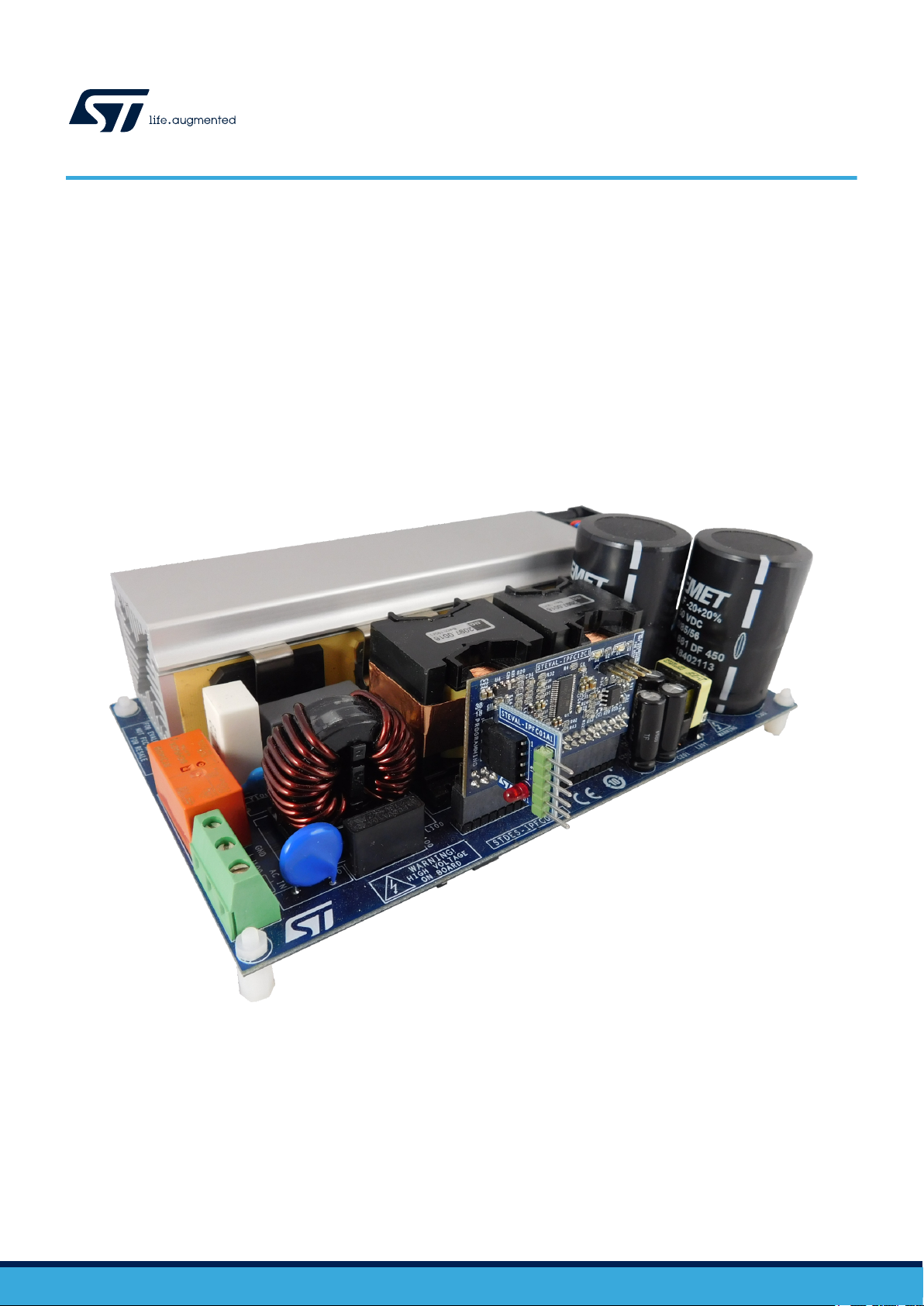
The STEVAL-IPFC02V1 2 kW interleaved PFC kit is based on the STNRGPF02 digital controller and consists of a power board,
control board and adapter board. The digital configurable ASIC can drive up to two channels in an interleaved PFC for industrial
applications.
The STNRGPF02 embedded on the control board implements mixed signal (analog/digital) average current mode control in
CCM at fixed frequency. The analog section ensures cycle-by-cycle current regulation, while digital control manages the nontime-critical operations. You can use the eDesignSuite software available on the ST website to configure the digital controller
according to specific application requirements.
Figure 1. STEVAL-IPFC02V1 evaluation kit with power, control and adapter boards
UM2674 - Rev 3 - January 2021
For further information contact your local STMicroelectronics sales office.
www.st.com

1 Safety instructions
Danger:
The evaluation board uses voltage levels that can cause serious injury and even death.
Do not touch any components immediately after disconnecting the input power supply as the
charged capacitors need time to discharge.
Due to the high power density, board components and heat sinks can become very hot and cause
severe burns when touched.
This board is intended for use by skilled technical personnel who are suitably qualified and familiar with the
installation, use and maintenance of power electronic systems. The same personnel must be aware of and must
apply national accident prevention rules.
The electrical installation shall be completed in accordance with the appropriate requirements (e.g., crosssectional areas of conductors, fusing, and GND connections).
UM2674
Safety instructions
UM2674 - Rev 3
page 2/28
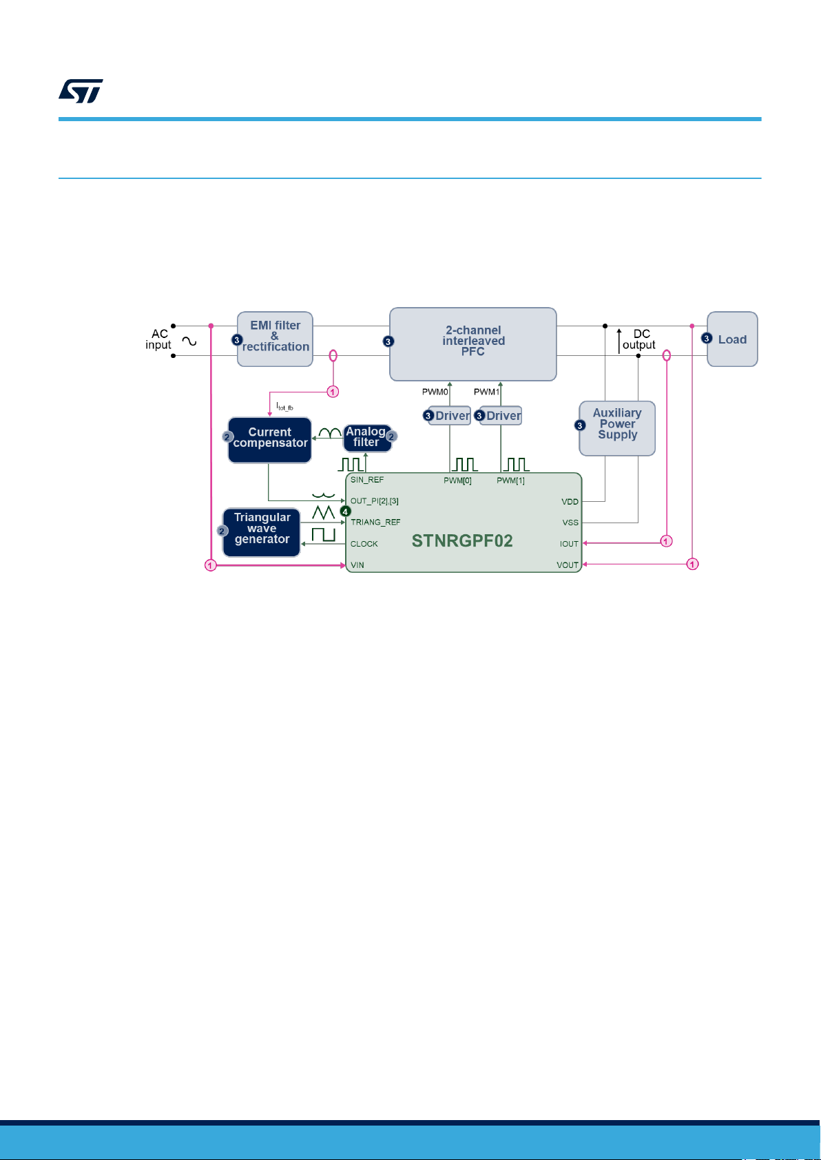
2 STEVAL-IPFC02V1 evaluation kit overview
Figure 2. STEVAL-IPFC02V1 block diagram
1. I/O measurement signals
2. Analog circuitry
3. Power stages
4. Digital control section
UM2674
STEVAL-IPFC02V1 evaluation kit overview
2.1
The STEVAL-IPFC02V1 implements mixed signal (analog/digital) control, combining the flexibility of a
programmable high end digital solution with the responsiveness and accuracy of analog componentry. The
inner current loop consists of an analog proportional-integral (PI) compensator that ensures the highest possible
bandwidth and cycle-by-cycle regulation. The outer voltage loop is performed by a digital PI controller with fast
dynamic response.
Board features
The 2 kW interleaved PFC evaluation kit features:
• A modular design with the following separate boards:
– STEVAL-IPFC02P1 power board
– STEVAL-IPFC02C1 control board
– STEVAL-IPFC01A1 adapter board
• 2-channel interleaved PFC
• Input voltage range: 90 to 265 VAC (50 or 60 Hz)
• Maximum output power: 2 kW at 230 VAC; 1 kW at 115 VAC;
• Output voltage: 400 V
• Fixed frequency average current mode control and CCM operation
• Mixed-signal, semi-digital approach
• Programmable phase shedding
• Cooling System management
• Programmable fast overcurrent and thermal protection
• Digital inrush current limiter function performed with relay
• Soft startup and burst mode management
• Load current and input voltage feed forward
• Channel current balance function
UM2674 - Rev 3
page 3/28

• Two status LEDs to signal nominal and fault conditions
• Browser GUI tool (eDesignSuite) for driver customization
• Serial communication port for
– STNRGPF02 programming
– PFC parameter monitoring
UM2674
Board features
UM2674 - Rev 3
page 4/28
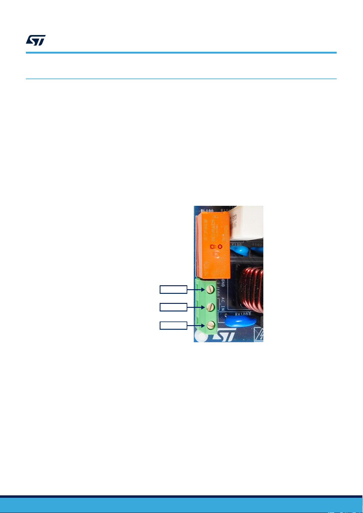
EARTH
AC LINE
AC LINE
How to use the STEVAL-IPFC02V1 evaluation board
3 How to use the STEVAL-IPFC02V1 evaluation board
To perform functional and efficiency testing, you need the following equipment:
• Programmable AC source with power > 2 kW
• DC electronic load or load resistor > 2 kW
• Power analyzer
• Digital oscilloscope
The STEVAL-IPFC02V1 board can be tested up to 2 kW at 230 V
range between 47 and 63 Hz.
Note: Any load or passive oscilloscope probe must be isolated from the input source of the PFC.
3.1 How to connect and start the STEVAL-IPFC02P1 power board
Step 1. Insert the STEVAL-IPFC02C1 control board in connector J100 on the STEVAL-IPFC02P1 power board.
Figure 3. STEVAL-IPFC02P1 AC supply connection
and 1 kW at 115 V
RMS
, in a frequency
RMS
UM2674
UM2674 - Rev 3
page 5/28
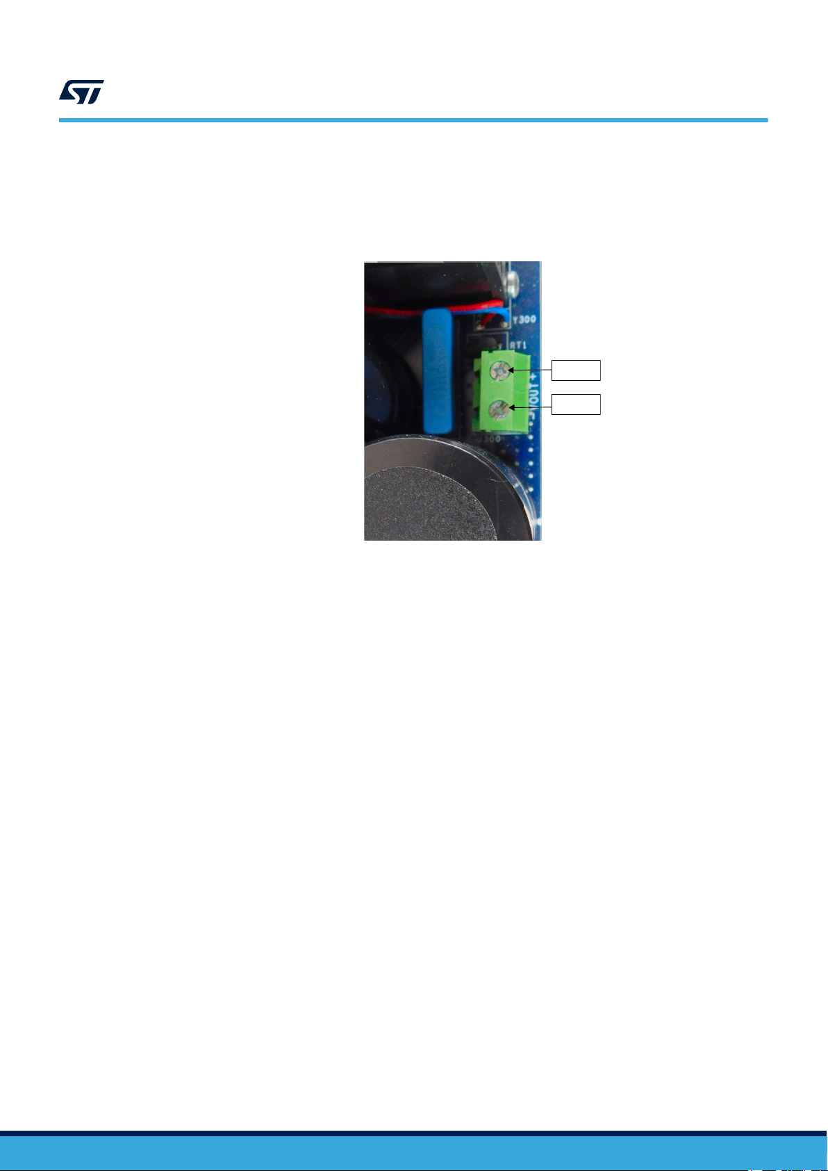
+400V
GND
UM2674
How to connect and start the STEVAL-IPFC02P1 power board
Step 2. Connect the load wires to the output terminals on J300 of the STEVAL-IPFC02P1 power board.
The actual load (electronic dc load, load resistors, inverter, etc.) must remain disconnected until the
soft startup sequence has completed.
The correct polarity is indicated on the board.
Figure 4. STEVAL-IPFC02P1 DC output connection
Step 3. Supply the following input voltage while no load is connected on the output:
– 90 – 265 VAC (50 or 60 Hz)
Step 4. Apply the load.
max: 2 kW at 230 VAC, 1 kW at 115 V
AC
3.1.1 STEVAL-IPFC02P1 power board startup sequence
1. The appropriate AC input voltage is applied under a no load condition.
2. When the input voltage rises above 60 V, the auxiliary power supply starts and generates the auxiliary
voltages (13 VDC and 5 VDC) for the drivers and the signal conditioning circuitry.
UM2674 - Rev 3
page 6/28
0
13V
0
V_INPUT
5V
5V
A A A A A A
5V
RELAY
ZVD
VIN_L1
R108
33k
R102
33k
RV100
S14K27 5
- +
D101
50A
2
1
3
4
D100
STPS 1L30A
D103
BAS70-04 FILM
3
1
2
R104
470k
N.M.
R107
10M
D104
BAS70-04 FILM
3
1
2
ISO100
TLP385(E
12
43
R114
3k
0.1%
R106
100k
R123
3k
0.1%
R101
150
R112
470k
C111
100pF
R121
470k
C101
0.1uF
R103
470k
N.M.
L100
2x4.5mH
2 1
3 4
C100
100nF
Y101
2.2nF
C110
100pF
R100 22
R113
470k
J100
VIN
1
2
3
R122
470k
R105
33k
Q100
STS6 NF20V
6
4
213 5
7
8
R111
10M
C102
1nF
D102
GF1M
RL100
250Vac -16A
11
1
A1
A2
3
12
2
14
Y100
2.2nF
R110
47k
F100
20A 250 Vac
R109
33k
AC-IN-L2
L1
L2
AC-IN-L1
L1 VDDIO
L2
VIN_L2
UM2674
How to connect and start the STEVAL-IPFC02P1 power board
3. Once the auxiliary voltages are nominal, the inrush current limiter phase begins by charging the output
capacitor until the DC voltage reaches the peak input voltage. The current is limited by resistor R101 until it
is shorted by the relay RL100 at the end of inrush phase.
Figure 5. STEVAL-IPFC02P1 input section
4. After the inrush limiter phase, the soft startup procedure is activated and the output voltage rises up to 436
VDC, at which point the PFC enters burst mode to regulate the output voltage between 416 and 436 VDC.
5. The green LED D2 on the control board indicates when the sequence has finished and the PFC is ready for
the load to be connected.
6. Once you connect the load:
– the output voltage is regulated to 400 V ±2 V.
– for 185 – 265 VAC, the maximum output power is 2000 W
– for 90 – 140 VAC, the maximum output power is 1000 W
UM2674 - Rev 3
page 7/28
PFC controller customization with eDesignSuite
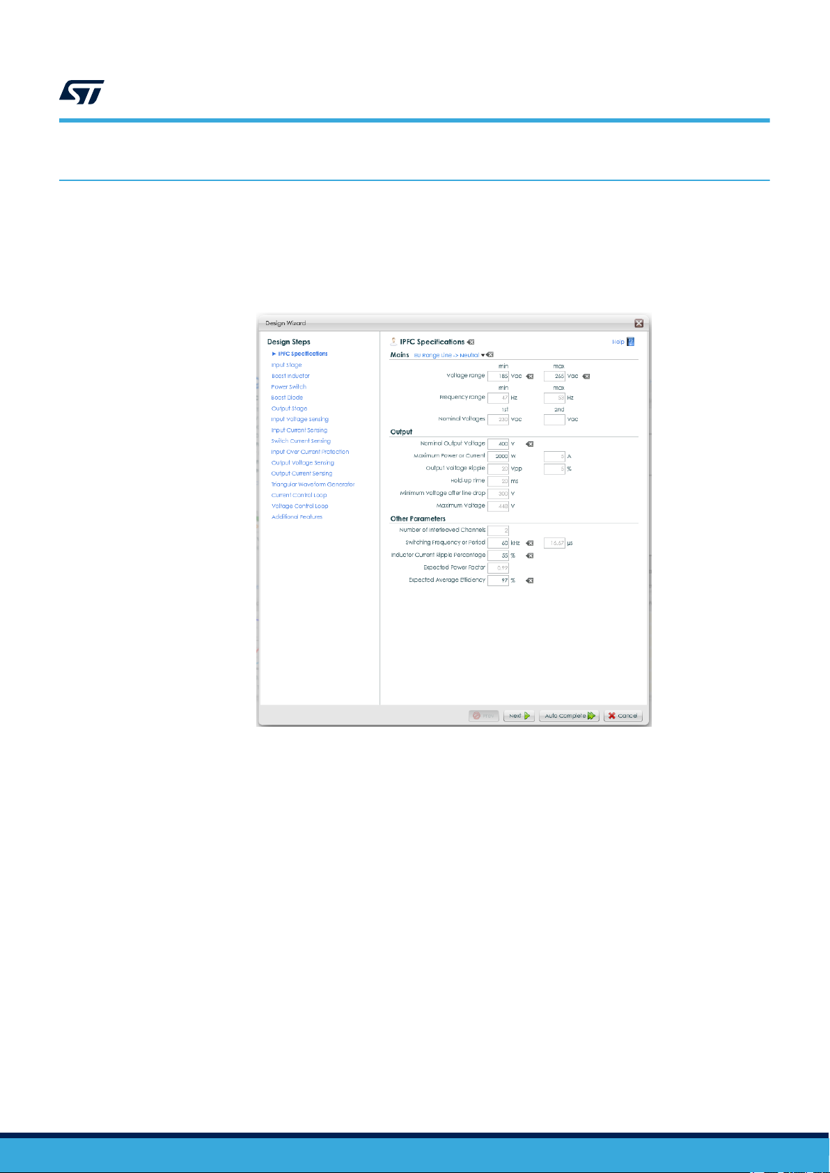
4 PFC controller customization with eDesignSuite
The eDesignSuite software tool developed by STMicroelectronics helps you configure ST products for power
conversion applications. You can use it to customize the PFC controller for a specific application by entering the
main specifications for your application and generating an automatic design, or by following a guided process for
more specific designs.
Figure 6. PFC specifications
UM2674
UM2674 - Rev 3
page 8/28

UM2674
Status LEDs and fault conditions
5 Status LEDs and fault conditions
The STEVAL-IPFC02C1 control board has the following status LEDs:
• a green LED connected to STNRGPF02 pin 15 (PFC_OK)
• a red LED connected to STNRGPF02 pin 14 (PFC_FAULT)
5.1 Normal operation
During normal operation, the green LED (D2) on the STEVAL-IPFC02C1 control board remains lit to indicate that
the PFC is operating under allowable conditions.
5.2 Fault conditions
When a fault is detected, the red LED (D1) on the STEVAL-IPFC02C1 control board lights up and the green LED
(D2) turns off. The device stops all switching activities and turns off the fan.
After a fault condition, the board must be reset by switching off the AC input voltage and discharging the output
capacitors.
Note: Warning: Do not short the output terminals to discharge the capacitors as the high discharge current may
damage the output current sensing circuitry.
The following conditions will trigger a fault protection:
• Highly distorted input voltage waveforms that inhibit frequency measurement. For example, if the mains
frequency out of the accepted range (e.g., 47-63 Hz).
• Overcurrent condition on at least one PFC channel. This protection prevents PFC inductor saturation.
• Overvoltage protection on output voltage if the output voltage exceeds 450 V
• Overvoltage protection on input voltage:
– for 115 VAC nominal supply: above 140 V
– for 230 VAC nominal supply: above 265 V
• Over-temperature protection when the ambient temperature of the board exceeds the threshold setting.
DC
5.3 Wait conditions
In addition to the conditions that trigger PFC_OK and PFC_FAULT, there are other conditions that are indicated
with both LEDs are off:
• Undervoltage condition on the output when the DC bus voltage falls below 340 V.
• Undervoltage condition on input when the input rms voltage falls below 90 VAC for 115 VAC nominal (or
185 VAC for 230 VAC nominal).
• Input voltage dropout when the input voltage signal disappears for more than 25 ms.
Under these conditions, the STNRGPF02 will drive both LEDs on the control board off and will wait until the
conditions have cleared before repeating the startup sequence.
UM2674 - Rev 3
page 9/28

0
13V
0
V_INPUT
5V
5V
A A A A A A
5V
RELAY
ZVD
VIN_L1
R10 8
33k
R10 2
33k
RV100
S1 4K275
- +
D101
50A
2
1
3
4
D100
STP S1L30 A
D103
BAS70-0 4FILM
3
1
2
R10 4
470 k
N.M.
R10 7
10M
D104
BAS70-0 4FILM
3
1
2
ISO10 0
TLP385 (E
12
43
R11 4
3k
0.1%
R10 6
100 k
R12 3
3k
0.1%
R10 1
150
R11 2
470 k
C11 1
100 pF
R12 1
470 k
C10 1
0.1u F
R10 3
470 k
N.M.
L100
2x4.5 mH
2 1
3 4
C10 0
100 nF
Y101
2.2n F
C11 0
100 pF
R10 0 22
R11 3
470 k
J1 00
VIN
1
2
3
R12 2
470 k
R10 5
33k
Q10 0
STS 6NF20 V
6
4
213 5
7
8
R11 1
10M
C10 2
1nF
D102
GF1 M
RL100
250 Vac -16A
11
1
A1
A2
3
12
2
14
Y100
2.2n F
R11 0
47k
F10 0
20A 25 0Vac
R10 9
33k
AC-IN-L2
L1
L2
AC-IN-L1
L1 VDDIO
L2
VIN_L2
UM2674 - Rev 3
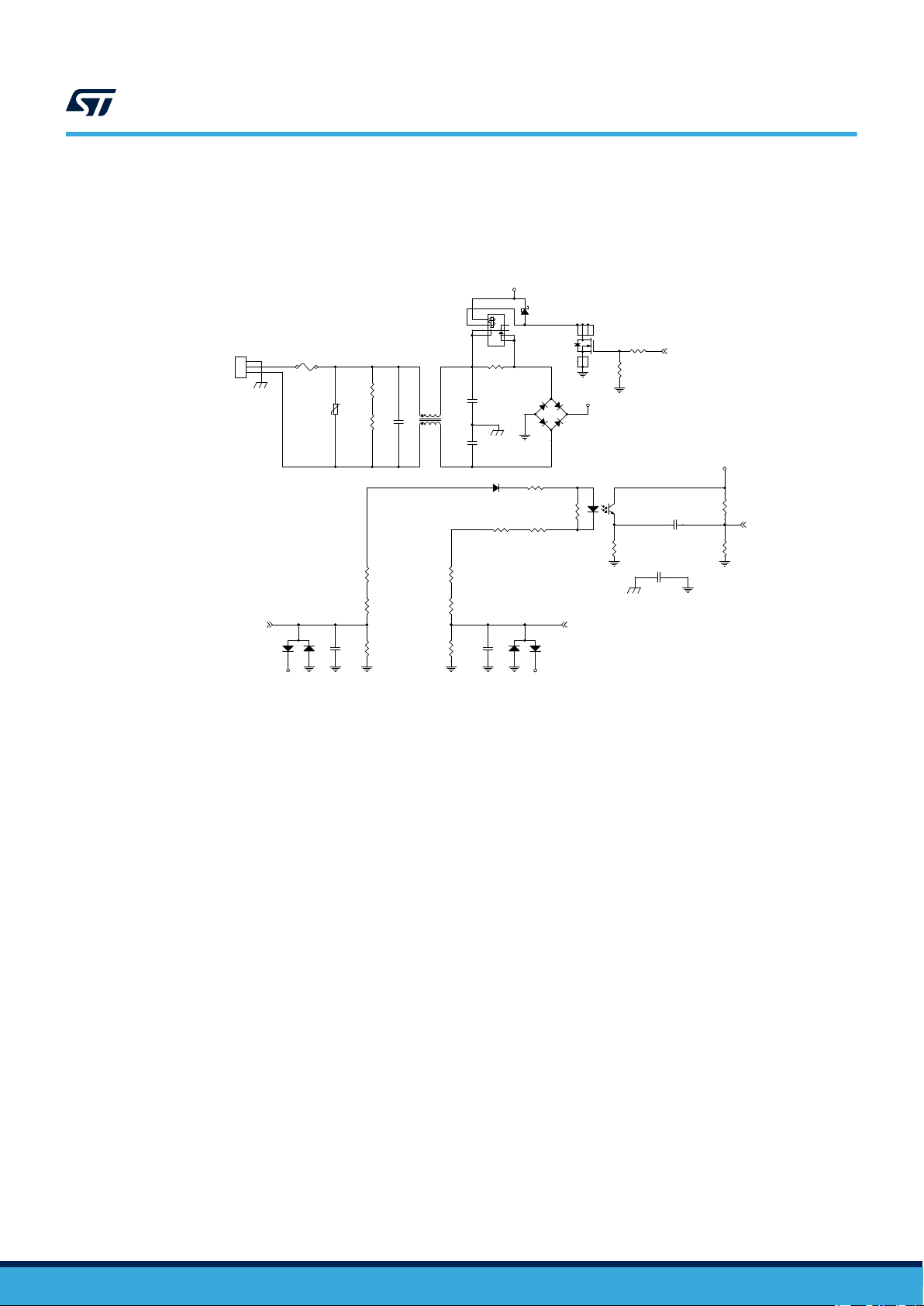
6 STEVAL-IPFC02V1 schematic diagrams
Figure 7. STEVAL-IPFC02P1 schematic - input section
page 10/28
Schematic diagrams
UM2674

5V
13V
+40 0V
D203
STPS1L30A
D204
TMMBAT46FILM
C206
4.7 uF
+
C203
470uF
12
R205
2.7
L201
2198.00 37
1
5
4
3
10
8
7
6
R203
24k
R202
12k
C200
470nF
C207
4.7 uF
L200
4.7 uH
1 2
D202
STTH1L06A
R200
22
D200
SM6T220A
C210
1nF
D201
STPS2150A
C209
4.7 nF
R207
3.3 k
U200
L4931ABD50-TR
VOUT
1
GND1
2
GND2
3
NC
4
INHIBIT
5
GND3
6
GND4
7
VIN
8
+
C205
10uF
12
R204
2.7
R206
24k
U201
ALTAIR05T-800
COMP
7
DRAIN4
16
IREF
5
FB
6
VDD
3
GND4SRC1
1
SRC2
2
DRAIN315DRAIN214DRAIN1
13
+
C201
470uF
12
R201
33k
C208
470nF
+
C202
470uF
12
C204
470nF
6.5V
UM2674 - Rev 3
Figure 8. STEVAL-IPFC02P1 schematic - auxiliary power supply
page 11/28
Schematic diagrams
UM2674
13V
V_INPUT
5V
13V
+400 V
0
A
5V
13V
5V
5V
5V
13V13V
5V 5V
A A
5V 5V
ZVD ZVD
VIN_L1 VIN_L1
VIN_L2 VIN_L2
RELAY
C30 4
1uF
D306
STP S1 L30A
C31 1
0.1u F
L301
209 7.00 16
34
12
25
C30 9
100 pF
C31 2
0.1u F
D309
TMMBAT46FILM
C31 9
0.1u F
R34 6
62k
0.1%
D303
STP S1 L30A
R32 8
*
N.M.
C32 3
0.1u F
R33 5 22
R30 1
100
R34 0
2.2k 0.1%
D301
STP SC 120 65D
R34 1
100
D310 TMMBAT46FILM
R34 2
2.2k 0.1%
R32 7
2.2k 0.1%
D307
STP S1 L30A
U302
STLM20 W87 F
NC
1
GND
2
VOUT3VCC
4
GND1
5
R30 2
100
U306
PM88 34
EN1
1
PWM1
2
GND
3
PWM24OUT2
5
Vcc
6
OUT1
7
EN2
8
U305
PM88 34
EN1
1
PWM1
2
GND
3
PWM24OUT2
5
Vcc
6
OUT1
7
EN2
8
R33 9
100
R30 5
1k
C30 5
10n F
R33 4
2.2k 0.1%
-
+
U303
TSV91 1ILT
3
4
1
52
C31 0
100 pF
R34 9
510
R31 7
10k
-
+
U301
TSV91 1ILT
3
4
1
52
R33 3
100
C30 6
0.1u F
R31 0 33
R32 5
2.2k 0.1%
R30 8
10k
0.1%
C31 6
0.1u F
C31 8
150 pF
R32 0
6m
R31 1 33
+
C30 2
680 uF
12
R30 3
470 k
R31 5
10k
C307 10 0pF
L300
209 7.00 16
34
12
25
R30 7
10k
0.1%
R35 0
510
-
+
U304
TSV91 1ILT
3
4
1
52
D304
STP S1 L30A
D308
STP S1 L30A
R30 0
40m
R34 7 0
D300
STP SC 120 65D
R31 9
56k
0.1%
C31 5
0.1u F
C32 1
150 pF
R31 2 10
J30 0
VOUT
1
2
C30 8
100 pF
R32 4
82k
0.1%
Q30 0
STG W20 H65F B
23
1
C32 0
0.1u F
R30 6
470 k
R34 8 0
D305
STP S1 L30A
C31 3
0.1u F
R31 4
470 k
R32 2
100
C31 4
10n F
Q30 1
STG W20 H65F B
23
1
R32 9
470
R34 3
62k
0.1%
R33 0
82k
0.1%
R30 4
1k
R34 4
100
R31 3 10
J30 1
con 40-2 x20-strip-fe male
33
1 2
3 4
5 6
7 8
9 10
11 12
13 14
15 16
17 18
19 20
21 22
23 24
25 26
27 28
29 30
31 32
34
35 36
37 38
39 40
R31 6
10m
R32 1
100
C30 0
0.56 uF
Q30 2
STS 6NF2 0V
6
4
213 5
7
8
R31 8
10m
R33 1
62k
0.1%
R32 3
3.3k
0.1%
R33 2
11k
R33 6
62k
0.1%
R30 9
56k
0.1%
-
+
U300
TSV91 1ILT
3
4
1
52
t
RT1
16
D302
STP S1 L30A
R34 5
2.2k 0.1%
Y300
LAM 4 K 150 12
+
1
-
2
R33 8
10k
R32 6 0
R33 7
33k
C31 7
0.1u F
+
C30 1
680 uF
12
C32 2
0.1u F
VBUS
FAN TEMP
CS0
LOAD
CS1
CS1
CS0
I_1
I_0
OCP
PWM0
PWM1
OCP
I_tot
PW M0 PW M0
PW M1
I_0
PW M0
I_1
I_tot
FAN F AN
TEMP TEMP
VBUS VBUS
LOAD LOAD
OCP OCP
I_tot
RELAY
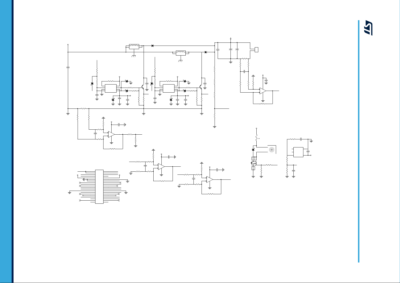
UM2674 - Rev 3
Figure 9. STEVAL-IPFC02P1 schematic - boost interleaving section
page 12/28
Schematic diagrams
UM2674

PROGRAMMING PORT
5V
AAA
A
5V
5V
5V
5V
5V
5V
5V
5V
A
5V
A
A
A
A
5V5V
A
5V
VDDA
A A
OUT_P I
-
+
U5B
LMV358IDT
7
6
5
4 8
R32
10k
R21
10k
R42 10 0k
-
+
U4
TSV911 ILT
3
4
1
52
R20
27k
D1
RED
C40
100p F
R26
56k
R55
N.M.
C27
820p F
D2
GRE EN
R54 10k
R41
N.M.
R30
22k
C42
1nF
C31
8.2n F
R15
10k
C7
1uF
+
C1
4.7u F
10V
C28
2.2 nF
R24 4. 3k
R22
10k
C3
10nF
C5
100n F
C8
100p F
C12
15nF
C4
10nF
R48
N.M.
R27
56k
R50
4.7k
C29 15 0pF
C30
15pF
-
+
U5A
LMV358IDT
1
2
3
4 8
R52
1k
R25 270 K
C35
1.5n F
R49
1.5k
R23
7.5k
C32 100n F
R1 1.8k
J5
CON4
1
2
3
4
R6 3.3k
R4 10 k
C10
33pF
R2 1.8k
C37
33pF
R40 0
R14
10k
R35 3.3k
R36
4.7k
C9
150p F
R8 10k
R29 0
L1
120 ohm-1 00MHz
R44 0
U1
STNR GPF 02
VDD
11
VDDA
29
VCOUT
13
VSS
12
VSSA
30
PWM[0]
1
SIN_REF
4
SET_O
5
OCP
19
PWM[1]
16
SCR [2]
8
PTX
22
RTX
23
FAN
20
RELAY/SCR[1]
21
PFC _FAULT
14
PFC _OK
15
RES [3]
10
RES [2]
9
VIN[0]
31
TEMP
32
IOUT
33
VOUT
34
I[0]
35
I[1]
36
RES [1]
37
VIN[1]
38
OUT_PI[3]
24
OUT_PI[2]
25
TRIANG_REF
26
OCP [1]
27
OCP [0]
28
CLOCK
2
OFFS ET
3
ENABLE
6
SYNCR
7
ZVD
17
SET_I
18
C11
1nF
R7 10k
R31
0
C24
100n F
C23
1uF
R37
2.7k
R43 10 0k
R28
5.6k
R9 10k
D3
BAS70- 05/S OT
C13
220n F
R45
N.M.
R33
N.M.
C41
1nF-N .M.
C39
220n F
C18 100n F
C2
100n F
R53
1k
C36
330p F
C38
220n F
R34
15k
J2
CON4
1
2
3
4
J1
CON4 0A
1 2
3 4
5 6
7 8
9 10
11 1 2
13 1 4
15 1 6
17 1 8
19 2 0
21 2 2
23 2 4
25 2 6
27 2 8
29 3 0
31 3 2
33 3 4
35 3 6
37 3 8
39 4 0
OFFS ET
PW M0
OUT_P I
TRIANG RE F
CLOCK
TRIANG RE F
SIN_RE F
I_ref
GRE EN LED
RED LE D
PW M1
PW M0
ZVD
SCR _1
FAN
I_ref
VIN_L1
VBUS
LOAD
I_tot
PW M0
SCR _1
LOAD
VIN_L1
LOAD
VIN_L1
TEMP
VBUS
TEMP
VBUS
ZVD
FAN
SIN_RE F
SET
PW M0
I_0
I_1
RTX
PTX
I_tot
I_0
I_1
SCR _2
OFFS ET
OCP OCP
PW M0
CLOCK
CLOCK
SCR _2
NRST
RED LE D
GRE EN LED
PW M1
ZVD SET
OCP FAN
SCR _1
OCP [1]
VDDA
TEMP
I_0_F
OCP [0]
I_1_F
VIN_L2
VIN_L2
VIN_L2I_1
I_0
I_tot
page 13/28
UM2674 - Rev 3
Figure 10. STEVAL-IPFC02C1 schematic
Schematic diagrams
UM2674

J4 01
CON6
12345
6
R40 2
470 k
J4 00
CON4
123
4
567
8
D400
LED
R40 1 330
Q40 0
MMBT222 2ALT1G
1
32
R40 3
1k
GRE EN
BLACK
YELLOW
ORANGE
RED
BROWN
YELLOW
ORANGE
RED
UM2674 - Rev 3
Figure 11. STEVAL-IPFC01A1 schematic
page 14/28
Schematic diagrams
UM2674

7 STEVAL-IPFC02V1 bill of materials
Table 1. STEVAL-IPFC02V1 bill of materials
Item Q.ty Ref. Part / Value Description Manufacturer Order code
1 1 -
2 1 -
3 1 -
7.1 STEVAL-IPFC02P1 power board bill of materials
Item Q.ty Ref. Part / Value Description Manufacturer Order code
1 1 C100
2 1 C101
3 1 C102
4 4
5 3
6 3
7 1 C205 10µF, 16V
8 2 C206, C207
9 1 C209
10 1 C210 1nF, 25V, ±10%
C110, C111,
C309, C310
C200, C204,
C208
C201, C202,
C203
STEVALIPFC02P1
STEVALIPFC02C1
STEVALIPFC01A1
Power board ST not available separately
Control board ST not available separately
Adapter board ST not available separately
Table 2. STEVAL-IPFC02P1 bill of materials
Safety Capacitors
100nF, 275VAC,
±20%
0.1µF, 25V,
±10%
1nF, 760VAC,
±20%
100pF, 50V,
±5%
470nF, 25V,
±10%
470µF, 25V,
±20%
4.7µF, 50V,
±20%
4.7nF, 25V,
±10%
MPP L/
S=15mm, Radial,
17.5x5x12mm, LS
15mm
CAP CER X7R
0603, 0603 (1608
Metric)
CAP CER Y5U
RADIAL, Radial,
Disc
CAP CER C0G/NP0
0603, 0603 (1608
Metric)
CAP CER X7R
0603, 0603 (1608
Metric)
Cap Pol Radial
(Electrolytic); 3.50
mm C X 8.00 mm
Dia X 20.00 mm
H body, Radial,
8x20mm
Cap Pol Radial
(Electrolytic); 1.50
mm C X 4.00 mm
Dia X 7.00 mm
H body, Radial,
4x7mm
CAP CER X7R
1210, 1210 (3225
Metric)
CAP CER X7R
0603, 0603 (1608
Metric)
CAP CER X7R
0603, 0603 (1608
Metric)
UM2674
Bill of materials
Panasonic ECQ-UAAF104MA
KEMET C0603C104K3RACTU
Vishay BC
Components
Murata
Electronics
North America
Wurth
Electronics Inc.
Any -
- -
Taiyo Yuden UMK325B7475MM-T
Wurth
Electronics Inc.
Samsung
ElectroMechanics
VY1102M35Y5UG63V0
GRM1885C1H101JA01D
885012206075
885012206063
CL10B102KA8NNNC
UM2674 - Rev 3
page 15/28

UM2674
Bill of materials
Item Q.ty Ref. Part / Value Description Manufacturer Order code
CAP FILM
RAD, Radial,
26.5x6x15mm LS
22.5
ALU SNAP IN,
Radial, Can - Snap-InKEMET ALA7DA681DF450
EPCOS (TDK) B32673P6564K000
11 1 C300
12 2 C301, C302
0.56µF, 630Vdc,
±10%
680µF, 450V,
±20%
13 1 C304
14 2 C305, C314
C306, C313,
15 7
16 2 C307, C308
17 4
18 2 C318, C321
19 9
20 1 D101 50A, 1kV, 50A
21 1 D102 GF1M, 1kV, 1A
22 2 D103, D104 70V, 70mA (DC)
23 1 D200 220V
24 1 D201 150V, 2A
25 1 D202 600V, 1A
26 3
C315, C316,
C317, C319,
C320
C311, C312,
C322, C323
D100, D203,
D302, D303,
D304, D305,
D306, D307,
D308
D204, D309,
D310
1µF, 277V-a.c.,
520V c.c., ±10%
10nF, 50V,
±10%
0.1µF, 50V,
±10%
100pF, 630Vdc,
±5%
0.1µF, 50V, ±5%
150pF, 50 VDC,
±1%
STPS1L30A,
30V, 1A
100V, 150mA
(DC)
CAP FILM RADIAL,
Radial
CAP CER X7R
0603, 0603 (1608
Metric)
CAP CER X7R
0603, 0603 (1608
Metric)
CAP FILM RADIAL,
Radial
CAP CER X7R
0603, 0603 (1608
Metric)
Multilayer Ceramic
Capacitors MLCC SMD/SMT 50volts
150pF C0G 1%,
0603 (1608 metric)
DIODE SCHOTTKY
SMA, DO-214AC,
SMA
BRIDGE RECT
1PHASE GBJ, 4SIP, GBJ
DIODE GEN PURP
SMA, DO-214AC,
SMA
DIODE ARRAY
SCHOTTKY
SOT23-3,
TO-236-3, SC-59,
SOT-23-3
TRANSIL DIODE
SMB, DO-214AA,
SMB
DIODE SCHOTTKY
SMA, DO-214AC,
SMA
Ultrafast high
voltage rectifier
SMA, DO-214AC,
SMA
DIODE SCHOTTKY
MINMLF, DO-213AA
(Glass)
EPCOS (TDK) B32673Z5105K000
Murata
Electronics
North America
KEMET C0603C104K5RACTU
KEMET PFR5101J630J11L4BULK
KEMET C0603C104J5RACTU
KEMET C0603C151F5GACTU
ST STPS1L30A
Micro
Commercial Co
ON
Semiconductor
ST BAS70-04FILM
ST SM6T220A
ST STPS2150A
ST STTH1L06A
ST TMMBAT46FILM
GRM188R71H103KA01D
GBJ5010-BP
GF1M
UM2674 - Rev 3
page 16/28

UM2674
Bill of materials
Item Q.ty Ref. Part / Value Description Manufacturer Order code
27 2 D300, D301 650V, 12A
28 1 F100
29 1 ISO100 TLP385(E
30 1 J100 VIN
31 1 J300 VOUT
32 1 J301
33 1 L100 2x4.5mH, 18A
34 1 L200
35 1 L201
36 2 L300, L301
37 2 Q100, Q302 20V, 6A
38 2 Q300, Q301
39 1 R100 22, 1/4W, ±1%
40 1 R101 150, 5W, ±5%
41 3
42 2
R102, R201,
R337
R103, R104 (not
mounted)
20A 250Vac,
250VAC 72VDC,
20A
con40-2x20strip-female
4.7µH, 1.9A,
±20%
11W, 80kHz,
2.2mH, 13V,
0.47A, ±10%
350µH 12A
1kW
650V, 40A,
168W
33k, 0.1W,
1/10W, ±1%
470k, 0.25W,
1/4W, ±1%
DIODE SCHOTTKY
TO220AC,
TO-220-2
FUSE BOARD MNT,
0.390" L x 0.120"
W x 0.125" H
(9.80mm x 3.05mm
x 3.18mm)
TRANSISTOR
OPTOCOUPLER; 4PIN SO, 6-SOIC
(0.295", 7.50mm
Width), 4 Leads
SCREW TERM
BLOCK PCB 3POS
7.5MM GREEN
SCREW TERM
BLOCK PCB 2POS
7.62MM
CONN RCPT
40POS .100" DUAL
GOLD
CMC 4.5MH 18A
2LN TH, Vertical, 4
PC Pin
Unshielded Wirewound SMD
Inductor 4.7 µH
±20% Wire-Wound
1.9A Idc, SMD
4.3x4x3.2mm
Switch Mode
Transformer,
Through hole
Power inductor,
PK
through hole
MOSFET N-CH
8SOIC, 8-SOIC
(0.154", 3.90mm
Width)
IGBT TO247,
TO-247-3
CHIP RESISITOR
SMD 1206, 1206
(3216 Metric)
RES RADIAL,
Radial
CHIP RESISTOR
SMD 0603, 0603
(1608 Metric)
RES SMD 1206,
1206 (3216 Metric)
ST STPSC12065D
Bel Fuse Inc. SMM 20
Toshiba
Semiconductor
and Storage
Phoenix Contact 1717033
RS Pro 7901130
Samtec Inc. ESQ-120-37-G-D
Wurth
Electronics Inc.
RS PRO 7409372
AQ Magnetica
OR
Würth Elektronik
AQ Magnetica
OR
Würth Elektronik
ST STS6NF20V
ST STGW20H65FB
- -
TE Connectivity
Passive Product
- -
- -
TLP385(E
7448051804
2198.0037
OR
750318021
2097.0016
OR
750318020
SQMW5150RJ
UM2674 - Rev 3
page 17/28

UM2674
Bill of materials
Item Q.ty Ref. Part / Value Description Manufacturer Order code
43 3
44 1 R106
45 2 R107, R111
46 1 R110
47 7
48 2 R114, R123
49 2 R200, R335
50 1 R202
51 2 R203, R206
52 2 R204, R205
53 1 R207
54 1 R300 40mΩ, 7W, ±1%
55 8
56 2 R304, R305
57 2 R307, R308
58 2 R309, R319
59 2 R310, R311
60 2 R312, R313
R105, R108,
R109
R112, R113,
R121, R122,
R303, R306,
R314
R301, R302,
R321, R322,
R333, R339,
R341, R344
33k, 0.25W,
1/4W, ±1%
100k, 0.25W,
1/4W, ±1%
10M, 0.1W,
1/10W, ±1%
47k, 0.1W,
1/10W, ±1%
470k, 0.25W,
1/4W, ±1%
3k, 0.1W,
1/10W, ±0.1%
22, 0.25W,
1/4W, ±1%
12k, 0.1W,
1/10W, ±1%
24k, 0.1W,
1/10W, ±1%
2.7, 0.5W, 1/2W,
±1%
3.3k, 0.25W,
1/4W, ±1%
100, 0.1W,
1/10W, ±1%
1k, 0.1W,
1/10W, ±1%
10k, 0.1W,
1/10W, ±0.1%
56k, 0.1W,
1/10W, ±0.1%
33, 0.25W,
1/4W, ±1%
10, 0.25W,
1/4W, ±1%
CHIP RESISTOR
SMD 1206, 1206
(3216 Metric)
CHIP RESISTOR
SMD 1206, 1206
(3216 Metric)
CHIP RESISTOR
SMD 0603, 0603
(1608 Metric)
CHIP RESISTOR
SMD 0603, 0603
(1608 Metric)
CHIP RESISTOR
SMD 1206, 1206
(3216 Metric)
RES SMD 0603,
0603 (1608 Metric)
CHIP RESISTOR
SMD 1206, 1206
(3216 Metric)
CHIP RESISTOR
SMD 0603, 0603
(1608 Metric)
CHIP RESISTOR
SMD 0603, 0603
(1608 Metric)
RES SMD 1206,
1206 (3216 Metric)
CHIP RESISTOR
SMD 1206, 1206
(3216 Metric)
RES 2818,
Nonstandard
CHIP RESISTOR
SMD 0603, 0603
(1608 Metric)
CHIP RESISTOR
SMD 0603, 0603
(1608 Metric)
RES SMD 10K
OHM 0603, 0603
(1608 Metric)
RES SMD 56K
OHM 0603, 0603
(1608 Metric)
CHIP RESISTOR
SMD 1206, 1206
(3216 Metric)
CHIP RESISTOR
SMD 1206, 1206
(3216 Metric)
- -
- -
- -
- -
- -
Panasonic
Electronic
Components
- -
- -
- -
Susumu RL1632R-2R70-F
Any -
Vishay Dale WSHM2818R0400FEA
- -
- -
Panasonic
Electronic
Components
Panasonic
Electronic
Components
- -
- -
ERA-3AEB302V
ERA-3AEB103V
ERA-3AEB563V
UM2674 - Rev 3
page 18/28

UM2674
Bill of materials
Item Q.ty Ref. Part / Value Description Manufacturer Order code
61 2 R315, R317
62 2 R316, R318 10mΩ, 2W, ±1%
63 1 R320 6mΩ, 3W, ±1%
64 1 R323
65 2 R324, R330
66 6
67 1 R326
68 1
69 1 R329
70 4
71 1 R332
72 1 R338
73 2 R347, R348
74 2 R349, R350
75 1 RL100 250Vac-16A
76 1 RT1
77 1 RV100
78 1 U200 5V, 250mA
R325, R327,
R334, R340,
R342, R345
R328 (not
mounted)
R331, R336,
R343, R346
10k, 0.25W,
1/4W, ±1%
3.3k, 0.1W,
1/10W, ±0.1%
82k, 0.1W,
1/10W, ±0.1%
2.2K, 0.1W,
1/10W, ±0.1%
0, 0.1W, 1/10W,
±1%
*, 0.1W, 1/10W,
±1%
470, 0.1W,
1/10W, ±1%
62k, 0.1W,
1/10W, ±0.1%
11k, 0.1W,
1/10W, ±1%
10k, 0.1W,
1/10W, ±1%
0, 0.25W, 1/4W,
±1%
510, 0.1W,
1/10W, ±1%
16Ω, 1.7A,
±20%
S14K275,
275VAC
CHIP RESISTOR
SMD 1206, 1206
(3216 Metric)
RES 3264 current
sensing, 2512 (6432
Metric)
RES 2512, 2512
(6432 Metric)
RES SMD 0603,
0603 (1608 Metric)
RES SMD 0603,
0603 (1608 Metric)
RES SMD 0603,
0603 (1608 Metric)
CHIP RESISTOR
SMD 0603, 0603
(1608 Metric)
CHIP RESISTOR
SMD 0603, 0603
(1608 Metric)
CHIP RESISTOR
SMD 0603, 0603
(1608 Metric)
RES SMD 0603,
0603 (1608 Metric)
CHIP RESISTOR
SMD 0603, 0603
(1608 Metric)
CHIP RESISTOR
SMD 0603, 0603
(1608 Metric)
CHIP RESISTOR
SMD 1206, 1206
(3216 Metric)
CHIP RESISTOR
SMD 0603, 0603
(1608 Metric)
RELAY GEN
PURPOSE SPDT
16A 18V
ICL 8.5MM,
Diameter 8.5mm
VARISTOR 430V
4.5KA DISC 14MM,
Disc 14mm
IC REG LINEAR
8SO, 8-SOIC
(0.154", 3.90mm
Width)
- -
Ohmite MCS3264R010FER
Panasonic
Electronic
Components
Panasonic
Electronic
Components
Panasonic
Electronic
Components
Panasonic
Electronic
Components
- -
- -
- -
Panasonic
Electronic
Components
- -
- -
- -
- -
TE Connectivity
Potter &
Brumfield
Relays
EPCOS (TDK) B57153S0160M000
EPCOS (TDK) B72214S0271K101
ST L4931ABD50-TR
ERJ-MS4HF6M0U
ERA-3AEB332V
ERA-3AEB823V
ERA-3AEB222V
ERA-3AEB623V
RT314018
UM2674 - Rev 3
page 19/28

UM2674
Bill of materials
Item Q.ty Ref. Part / Value Description Manufacturer Order code
IC PRIMARY
79 1 U201 -
80 4
81 1 U302 -
82 2 U305, U306 4A
83 2 Y100, Y101
84 1 Y300
85 5
86 1
87 4 Spacer D01496
88 4 Nut
89 2 Screws M3 x 10 mm Steel screw
90 2 Steel washers M3
U300, U301,
U303, U304
Y3 lock-inretaining springs
Thermal Film
140 x 25 mm
-
2.2nF, 250VAC,
±20%
LAM 4 K 150 12,
12V
THFU 1 retaining springs
-
DTRNNE 34814M3M3 Hexagon Full
SWITCHING REG
16SOIC, 16-SOIC
(0.154", 3.90mm
Width)
IC OPAMP GP
8MHZ RRO
SOT23-5, SC-74A,
SOT-753
SENS TEMP ANLG
VOLT SOT-323-5,
5-TSSOP, SC-70-5,
SOT-353
IC MOSFET DVR
DUAL 8SOIC, 8SOIC (0.154",
3.90mm Width)
CAP CER RADIAL,
Radial, Disc
Heatsink 40 x 40
x150 mm, with axial
fan 12V, integrated
Thermal
conductivity Thin
film 140 X 25 mm
Hex Threaded
Spacer
Nut Double ChamferTRFASTENINGS
Steel Plain M3
Washer
ST ALTAIR05T-800
ST TSV911ILT
ST STLM20W87F
ST PM8834
Murata
Electronics
North America
FISCHERELEK
TRONIK
Fischer
Elektronik
BERGQUIST BP100-0.005-00-12/12
DURATOOL D01496
TR
FASTENINGS
ANY ANY
DE2E3KY222MA3BM02F
LAM 4 K 150 12
THFU 1
DTRNNE 34814 M3
M310 PRSTMCZ100-
7.2 STEVAL-IPFC02C1 control board bill of materials
Table 3. STEVAL-IPFC02C1 bill of materials
Item Q.ty Ref. Part / Value Description Manufacturer Order code
X7R Ceramic
Capacitor, SMD
0805
X7R Ceramic
Capacitor, SMD
0603
X7R Ceramic
Capacitor, SMD
0603
X7R Ceramic
Capacitor, SMD
0603
UM2674 - Rev 3
1 1 C1
2 5
3 2 C3, C4
4 2 C7, C23 1µF, 25V, ±10%
C2, C5, C18,
C24, C32
4.7µF, 16V,
±10%
100nF, 50V,
±10%
10nF, 25V,
±10%
ANY ANY
ANY ANY
AVX 06033C103KAT2A
ANY ANY
page 20/28

UM2674
Bill of materials
Item Q.ty Ref. Part / Value Description Manufacturer Order code
5 2 C8, C40
6 2 C9, C29
7 2 C10, C37 33pF, 50V, ±5%
8 2 C11, C42 1nF, 50V, ±5%
9 1 C12
10 3 C13, C38, C39
11 1 C27
12 1 C28
13 1 C30 15pF, 50V, ±5%
14 1 C31
15 1 C35 1.5nF, 50V, ±5%
16 1 C36
17 1
18 1 D1
19 1 D2
20 1 D3
21 1 J1
C41 (not
mounted)
100pF, 50V,
±5%
150pF, 50V,
±5%
15nF, 50V,
±10%
220nF, 50V,
±10%
820pF, 50V,
±5%
2.2 nF, 50V,
±5%
8.2nF, 50V,
±10%
330pF, 50V,
±5%
1nF, 50V, ±5%
RED, 1,85,
20mA
GREEN, 2.1V,
20mA
BAS70-05, 70V,
70mA
CON40A,
250Vac, 3A
C0G Ceramic
Capacitor, SMD
0603
C0G Ceramic
Capacitor, SMD
0604
C0G Ceramic
Capacitor, SMD
0603
C0G Ceramic
Capacitor, SMD
0603
X7R Ceramic
Capacitor, SMD
0603
X7R Ceramic
Capacitor, SMD
0603
COG Ceramic
Capacitor, SMD
0603
C0G Ceramic
Capacitor, SMD
0603
COG Ceramic
Capacitor, SMD
0603
X7R Ceramic
Capacitor, SMD
0603
C0G Ceramic
Capacitor, SMD
0603
COG Ceramic
Capacitor, SMD
0603
X7R Ceramic
Capacitor, SMD
0603
High efficiency red
diffused LED 3mm,
SMD 0805
High efficiency
green diffused LED
3mm, SMD 0805
Low capacitance,
series inductance
and resistance
Schottky diode,
SOT23
Right angle PIN
header connector,
dual row, T. H.
lead spacing 2.54 x
2.54mm
ANY ANY
ANY ANY
ANY ANY
ANY ANY
ANY ANY
ANY ANY
ANY ANY
ANY ANY
ANY ANY
ANY ANY
ANY ANY
ANY ANY
ANY ANY
Kingbright KP-2012SRC-PRV
Kingbright KPHCM-2012CGCK
ST BAS70-05FILM
Wurth Elektronik 61304021021
UM2674 - Rev 3
page 21/28
UM2674
Bill of materials
Item Q.ty Ref. Part / Value Description Manufacturer Order code
22 2 J2, J5
23 1 L1
24 2 R1, R2
25 6
26 4
27 2 R6, R35
28 1 R20
29 1 R23
30 1 R24
31 1 R25
32 2 R26, R27
33 1 R28
34 4
35 1 R30
36 5
37 1 R34
38 2 R36, R50
39 1 R37
40 2 R42, R43
41 1 R49
42 2 R52, R53
43 1 U1 5V
44 1 U4 5V
R4, R8, R9,
R21, R22, R32
R7, R14, R15,
R54
R29, R31, R40,
R44
R33, R41, R45,
R48, R55 (not
mounted)
CON4, 250Vac,
3A
120 Ω-100MHz,
500 mA, ±25%
1.8k, 50V, 0.1,
±1%
10k, 50V, 0.1W,
±1%
10k, 50V, 0.1W,
±0.1%
3.3k, 50V, 0.1W,
±1%
27k, 50V, 0.1W,
±1%
7.5k, 50V, 0.1W,
±1%
4.3k, 50V, 0.1W,
±1%
270K, 50V,
0.1W, ±1%
56k, 50V, 0.1W,
±1%
5.6k, 50V, 0.1W,
±1%
0, 50V, 0.1W,
±1%
22k, 50V, 0.1W,
±1%
(not mounted),
50V, 0.1W, ±1%
15k, 50V, 0.1W,
±1%
4.7k, 50V, 0.1W,
±1%
2.7k, 50V, 0.1W,
±1%
100k, 50V,
0.1W, ±1%
1.5k, 50V, 0.1W,
±1%
1k, 50V, 0.1W,
±1%
T. H. PIN Header
Connector, single
row, T. H. lead
spacing 2.54mm
Ferrite, SMD 0603 Wurth Elektronik 74279262
Metal film resistor,
SMD 0603
Metal film resistor,
SMD 0603
Metal film resistor,
SMD 0603
Metal film resistor,
SMD 0603
Metal film resistor,
SMD 0603
Metal film resistor,
SMD 0603
Metal film resistor,
SMD 0603
Metal film resistor,
SMD 0603
Metal film resistor,
SMD 0603
Metal film resistor,
SMD 0604
Metal film resistor,
SMD 0603
Metal film resistor,
SMD 0603
Metal film resistor,
SMD 0603
Metal film resistor,
SMD 0603
Metal film resistor,
SMD 0603
Metal film resistor,
SMD 0603
Metal film resistor,
SMD 0603
Metal film resistor,
SMD 0603
Metal film resistor,
SMD 0603
Digital controller,
TSSOP38
Single rail to rail
I/O 8MHz OpAmp,
SOT23-5L
Wurth Elektronik 61300411121
ANY ANY
ANY ANY
Panasonic ERA3APB103V
ANY ANY
ANY ANY
ANY ANY
ANY ANY
ANY ANY
ANY ANY
ANY ANY
ANY ANY
ANY ANY
ANY ANY
ANY ANY
ANY ANY
ANY ANY
ANY ANY
ANY ANY
ANY ANY
ST STNRGPF02
ST TSV911ILT
UM2674 - Rev 3
page 22/28

Item Q.ty Ref. Part / Value Description Manufacturer Order code
45 1 U5 5V
Low power I/O rail
to rail dual OpAmp,
SO8
7.3 STEVAL-IPFC01A1 adapter board bill of materials
Table 4. STEVAL-IPFC01A1 bill of materials
Item Q.ty Ref. Part / Value Description Manufacturer Order code
1 1 D400 LED
2 1 J400 CON4
3 1 J401 CON6
4 1 Q400 40 V, 0.6 A
5 1 R401 330
6 1 R402 470k
7 1 R403 1K
High Efficiency Red
LED 3mm, through
hole
4-contact 2.54mm
female SIL Boardto-board Socket,
through hole
Right angle male
connector 1 way
6 circuits 2.54mm,
through hole
General Purpose
Transistors, NPN
Silicon
Metal film resistor,
0805
Metal film resistor,
0805
Metal film resistor,
0805
ST LMV358IDT
Kingbright L-7104ID
HARWIN M20-7890446
ANY ANY
ON
Semiconductor
ANY ANY
ANY ANY
ANY ANY
SMMBT2222ALT1G
UM2674
Bill of materials
UM2674 - Rev 3
page 23/28

Revision history
Date Version Changes
16-Mar-2020 1 Initial release.
10-Jul-2020 2 Updated Table 2.STEVAL-IPFC02P1 bill of materials.
22-Jan-2021 3 Updated Figure 10. STEVAL-IPFC02C1 schematic and Table 2. STEVAL-IPFC02P1 bill of materials
UM2674
Table 5. Document revision history
UM2674 - Rev 3
page 24/28

UM2674
Contents
Contents
1 Safety instructions ................................................................2
2 STEVAL-IPFC02V1 evaluation kit overview .........................................3
2.1 Board features .................................................................3
3 How to use the STEVAL-IPFC02V1 evaluation board................................5
3.1 How to connect and start the STEVAL-IPFC02P1 power board ........................5
3.1.1 STEVAL-IPFC02P1 power board startup sequence ..............................6
4 PFC controller customization with eDesignSuite ...................................8
5 Status LEDs and fault conditions ..................................................9
5.1 Normal operation...............................................................9
5.2 Fault conditions ................................................................9
5.3 Wait conditions ................................................................9
6 STEVAL-IPFC02V1 schematic diagrams ...........................................10
7 STEVAL-IPFC02V1 bill of materials................................................15
7.1 STEVAL-IPFC02P1 power board bill of materials ...................................15
7.2 STEVAL-IPFC02C1 control board bill of materials ..................................20
7.3 STEVAL-IPFC01A1 adapter board bill of materials..................................23
Revision history .......................................................................24
UM2674 - Rev 3
page 25/28

UM2674
List of figures
List of figures
Figure 1. STEVAL-IPFC02V1 evaluation kit with power, control and adapter boards ...........................1
Figure 2. STEVAL-IPFC02V1 block diagram ......................................................3
Figure 3. STEVAL-IPFC02P1 AC supply connection .................................................5
Figure 4. STEVAL-IPFC02P1 DC output connection .................................................6
Figure 5. STEVAL-IPFC02P1 input section .......................................................7
Figure 6. PFC specifications .................................................................8
Figure 7. STEVAL-IPFC02P1 schematic - input section .............................................. 10
Figure 8. STEVAL-IPFC02P1 schematic - auxiliary power supply ....................................... 11
Figure 9. STEVAL-IPFC02P1 schematic - boost interleaving section ..................................... 12
Figure 10. STEVAL-IPFC02C1 schematic ........................................................13
Figure 11. STEVAL-IPFC01A1 schematic ........................................................ 14
UM2674 - Rev 3
page 26/28

UM2674
List of tables
List of tables
Table 1. STEVAL-IPFC02V1 bill of materials ...................................................... 15
Table 2. STEVAL-IPFC02P1 bill of materials ...................................................... 15
Table 3. STEVAL-IPFC02C1 bill of materials ...................................................... 20
Table 4. STEVAL-IPFC01A1 bill of materials ...................................................... 23
Table 5. Document revision history .............................................................24
UM2674 - Rev 3
page 27/28

UM2674
IMPORTANT NOTICE – PLEASE READ CAREFULLY
STMicroelectronics NV and its subsidiaries (“ST”) reserve the right to make changes, corrections, enhancements, modifications, and improvements to ST
products and/or to this document at any time without notice. Purchasers should obtain the latest relevant information on ST products before placing orders. ST
products are sold pursuant to ST’s terms and conditions of sale in place at the time of order acknowledgement.
Purchasers are solely responsible for the choice, selection, and use of ST products and ST assumes no liability for application assistance or the design of
Purchasers’ products.
No license, express or implied, to any intellectual property right is granted by ST herein.
Resale of ST products with provisions different from the information set forth herein shall void any warranty granted by ST for such product.
ST and the ST logo are trademarks of ST. For additional information about ST trademarks, please refer to www.st.com/trademarks. All other product or service
names are the property of their respective owners.
Information in this document supersedes and replaces information previously supplied in any prior versions of this document.
© 2021 STMicroelectronics – All rights reserved
UM2674 - Rev 3
page 28/28
 Loading...