

Page 1
February 2017
DocID030279 Rev 1
1/24
www.st.com
UM2170
User manual
Getting started with smart home lighting based on HVLED815PF
and SPSGRF
Introduction
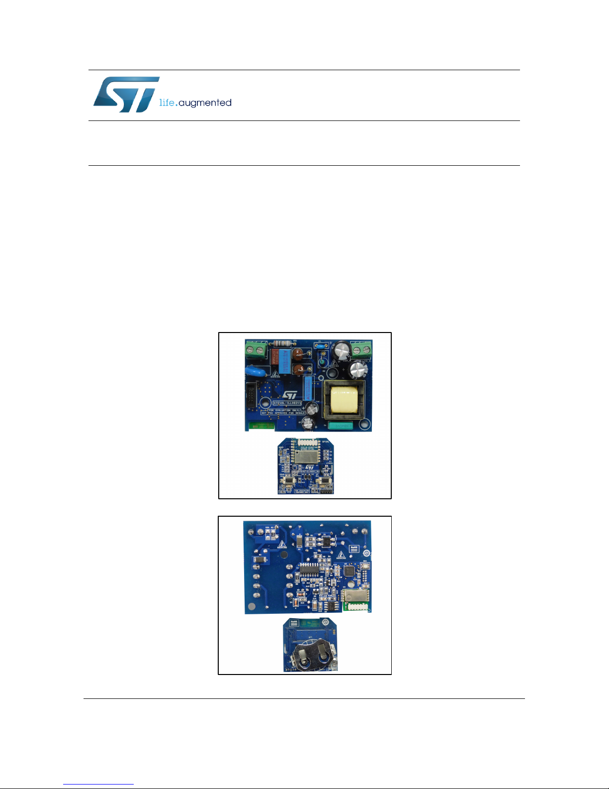
The STEVAL-ILL082V1 is based on the HVLED815PF off-line LED driver. It consists of a LED driver
board with a connectivity module and the STM32L0 microcontroller, which manages wireless
communication and LED brightness control. The microcontroller and connectivity module are supplied
by the LED driver through an auxiliary winding.
STEVAL-ILL082V1 can be operated in standalone mode through the communication with the bundled
STEVAL-ILL082V1_Remote controller based on SP1ML to help to reduce development and certification
time.
The board can also be rendered visible to cloud applications with the addition of a wireless bridge.
Figure 1: STEVAL-ILL082V1 evaluation board plus remote controller (top view)
Figure 2: STEVAL-ILL082V1 evaluation board plus remote controller (bottom view)
Page 2

Contents
UM2170
2/24
DocID030279 Rev 1
Contents
1 Overview .......................................................................................... 5
1.1 Smart home lighting architecture ....................................................... 5
1.2 Hardware description ........................................................................ 6
2 Getting started ................................................................................. 8
2.1 Smart home lighting board used with SPSGRF and SP1ML ............. 8
3 Efficiency testing and measurements ......................................... 10
3.1 Efficiency, power factor, THD, LED current and current regulation . 10
3.2 IEC61000-3-2 class C harmonic measurement............................... 13
3.3 LED dimming versus output power and LED current ...................... 13
3.4 Standby power consumption ........................................................... 13
4 Schematic diagrams ...................................................................... 15
5 Bill of materials .............................................................................. 18
6 Revision history ............................................................................ 23
Page 3

UM2170
List of tables
DocID030279 Rev 1
3/24
List of tables
Table 1: Test conditions ............................................................................................................................ 10
Table 2: Test results ................................................................................................................................. 10
Table 3: STEVAL-ILL082V1 bill of materials ............................................................................................ 18
Table 4: STEVAL-ILL082V1_Remote bill of materials .............................................................................. 21
Table 5: Document revision history .......................................................................................................... 23
Page 4

List of figures
UM2170
4/24
DocID030279 Rev 1
List of figures
Figure 1: STEVAL-ILL082V1 evaluation board plus remote controller (top view) ...................................... 1
Figure 2: STEVAL-ILL082V1 evaluation board plus remote controller (bottom view) ................................ 1
Figure 3: Smart home lighting architecture ................................................................................................. 5
Figure 4: STEVAL-ILL082V1 key components (top view) .......................................................................... 6
Figure 5: STEVAL-ILL082V1 key components (bottom view) .................................................................... 7
Figure 6: LED load connection ................................................................................................................... 8
Figure 7: SP1ML (STEVAL-ILL082V1_Remote) remote controller ............................................................ 9
Figure 8: STEVAL-ILL082V1 test setup.................................................................................................... 10
Figure 9: Input voltage versus LED current .............................................................................................. 11
Figure 10: Input voltage versus PF at full load ......................................................................................... 11
Figure 11: THD versus line variation ........................................................................................................ 12
Figure 12: Current regulation .................................................................................................................... 12
Figure 13: Efficiency curve ....................................................................................................................... 12
Figure 14: STEVAL-ILL082V1: full load condition .................................................................................... 13
Figure 15: STEVAL-ILL082V1: LED dimming linearity ............................................................................. 13
Figure 16: STEVAL-ILL082V1: standby consumption versus line variation ............................................. 14
Figure 17: STEVAL-ILL082V1 circuit schematic (1 of 2) .......................................................................... 15
Figure 18: STEVAL-ILL082V1 circuit schematic (2 of 2) .......................................................................... 16
Figure 19: STEVAL-ILL082V1_Remote circuit schematic ........................................................................ 17
Page 5
UM2170
Overview
DocID030279 Rev 1
5/24
1 Overview
The STEVAL-ILL082V1 features:
• Primary side regulation, no optocoupler required
• High power (> 0.95) and low (< 18%) over the entire voltage range
• Quasi resonant operation
• High efficiency (> 84%)
• Open/short LED management
• Up to 15 W operation
• Remote on/off and five steps dimming down to 2.5% using the STEVAL-
ILL082V1_Remote controller
• Low standby power consumption: < 0.5 W
• RoHS compliant
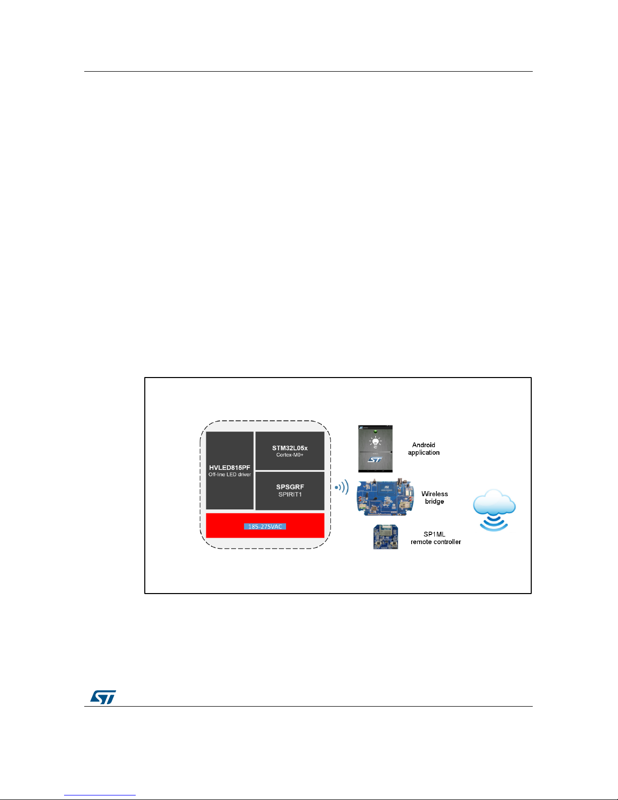
1.1 Smart home lighting architecture
The architecture behind this smart home lighting system involves an LED driver
(HVLED815PF) to supply and monitor the LED load, an STM32L05x microcontroller to
manage the board, a low power sub-GHz module based on the SPIRIT1 RF transceiver
(SPSGRF) for external communication and a remote application running on an Android
®
mobile device to display status information and generate remote commands.
Cloud-based IoT functionality is supported with the introduction of a separate ST wireless
bridge (STEVAL-IDI004V2) or through a remote controller (SP1ML).
Figure 3: Smart home lighting architecture
Page 6
Overview
UM2170
6/24
DocID030279 Rev 1
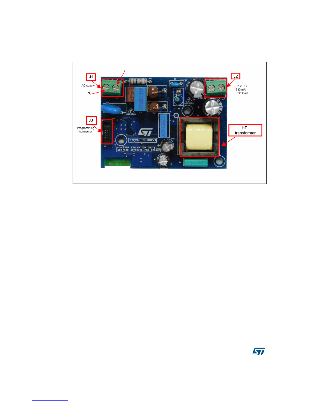
1.2 Hardware description
The top side of the STEVAL-ILL082V1 board is figured below.
Figure 4: STEVAL-ILL082V1 key components (top view)
Key top side components include:
• J1: the input connector for AC voltage input.
• J2: the output connector for the LED load.
• J3: the 10-pin/10-position shrouded connector for STM32 microcontroller firmware
development and debugging.
• HF transformer.
Page 7
UM2170
Overview
DocID030279 Rev 1
7/24
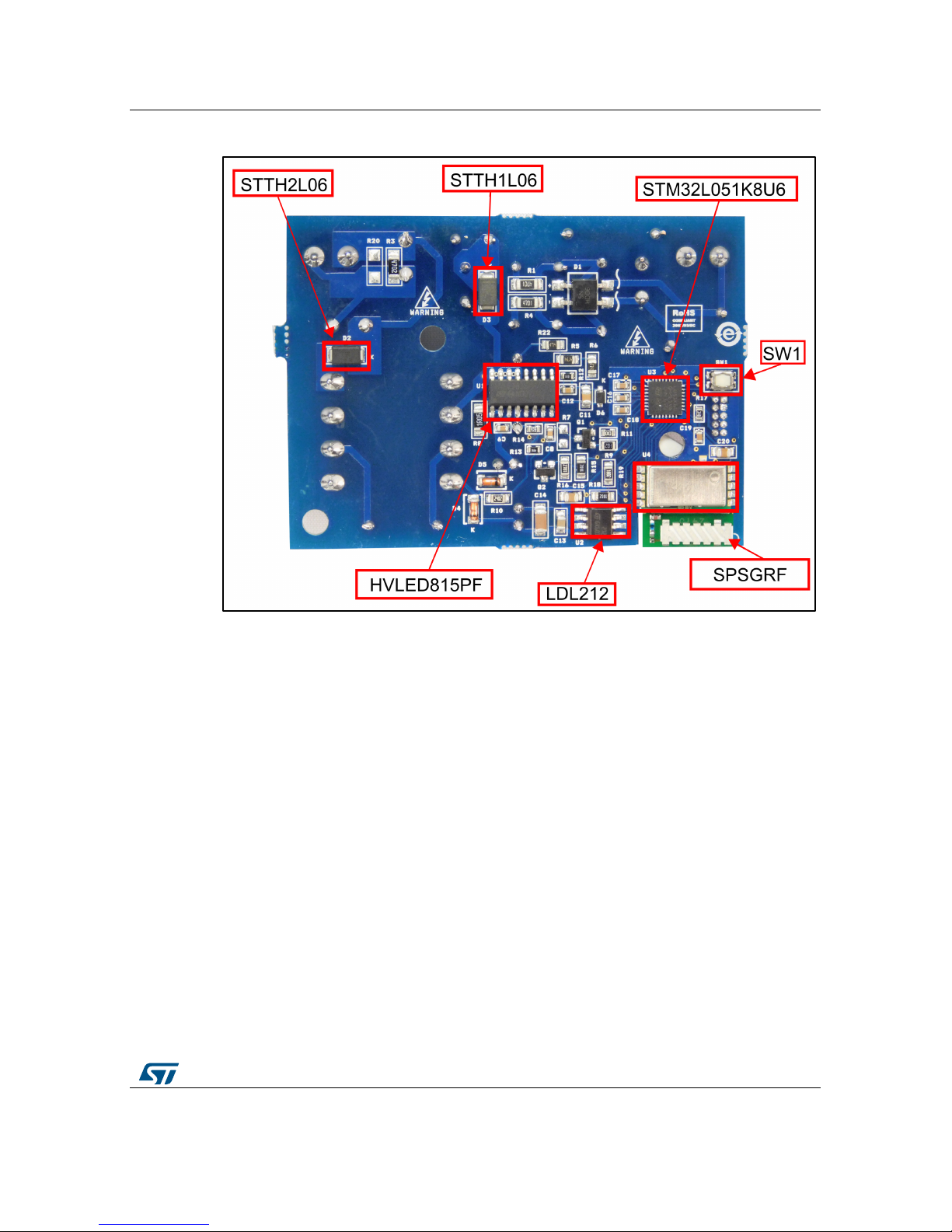
The bottom side of the STEVAL-ILL082V1 board is figured below.
Figure 5: STEVAL-ILL082V1 key components (bottom view)
Key bottom side components include:
• HVLED815PF: offline constant current LED driver with primary-sensing, integrated
MOSFET, high power factor, low THD and ability to supply 15 W controlled power.
• SPSGRF: low power sub-GHz module based on SPIRIT1 RF transceiver and BALUN.
It enables wireless connectivity requiring no RF experience or expertise for integration.
It has a programmable radio which supports different modulation schemes (e.g. FSK,
GFSK, MSK, GMSK, OOK and ASK). The output power can vary up to 11.6 dBm and
the receiver sensitivity is -118 dBm. Four GPIOs are available and can be
programmed for 32 different input/output functions. SPSGRF is FCC, IC and CE
certified. It is available in two different carrier frequency versions to cater 868 MHz
SRD and 915 MHz ISM bands.
• STM32L05x: ultra-low power 32-bit RISC microcontroller based on the ARM
®
Cortex®-
M0+ core, featuring an advanced APB bus, ADC, timer, I²C, SPI and USART.
• STTH1L06 and STTH2L06: ultra-fast high voltage rectifiers, with low reverse recovery
current and low thermal resistance.
• LDL212: a 3.3 V low dropout regulator (LDO) to supply the MCU and SPSGRF.
• SW1: reset switch for the microcontroller and connectivity module.
Page 8

Getting started
UM2170
8/24
DocID030279 Rev 1
2 Getting started
2.1 Smart home lighting board used with SPSGRF and SP1ML
1
Connect LED load (10 LED/32 V 322 mA) to J2.
2
Connect mains voltage (185 – 275 VAC) through input connector J1.
Figure 6: LED load connection
Page 9

UM2170
Getting started
DocID030279 Rev 1
9/24
3
Use SP1ML (STEVAL-ILL082V1_Remote) to control the LED brightness from 2.5%
to 100% or to switch LEDs on or off.
SW1 decreases output current and switches LEDs off.
SW2 increases output current and switches LEDs on.
Figure 7: SP1ML (STEVAL-ILL082V1_Remote) remote controller
Page 10

Efficiency testing and measurements
UM2170
10/24
DocID030279 Rev 1
3 Efficiency testing and measurements
3.1 Efficiency, power factor, THD, LED current and current
regulation
Table 1: Test conditions
Test conditions Devices
Input voltage: 185-275 VAC, 50 Hz
LED load: 32 V, 322 mA±1%
AC source: Agilent 6812B
Power analyzer: Yokogaba -WT310
Figure 8: STEVAL-ILL082V1 test setup
Table 2: Test results
Vin
(V)
Pin
(W)
Po
(W)
Efficiency
(%)
PF
THD
(%)
LED
current
Current regulation
(%)
185 12.19 10.28 84.35 0.98 11.50 325.00 0.87
200 12.13 10.24 84.42 0.99 5.10 324.18 0.61
205 12.10 10.21 84.38 0.99 4.00 323.46 0.39
210 12.08 10.19 84.34 0.99 4.20 322.80 0.18
220 12.03 10.15 84.34 0.99 6.00 321.40 -0.25
230 12.04 10.14 84.24 0.99 8.60 321.00 -0.37
250 12.03 10.10 83.97 0.98 13.00 320.19 -0.63
275 12.11 10.12 83.57 0.97 17.30 320.65 -0.48
Page 11

UM2170
Efficiency testing and measurements
DocID030279 Rev 1
11/24
Figure 9: Input voltage versus LED current
Figure 10: Input voltage versus PF at full load
Page 12

Efficiency testing and measurements
UM2170
12/24
DocID030279 Rev 1
Figure 11: THD versus line variation
Figure 12: Current regulation
Figure 13: Efficiency curve
Page 13

UM2170
Efficiency testing and measurements
DocID030279 Rev 1
13/24
3.2 IEC61000-3-2 class C harmonic measurement
The STEVAL-ILL082V1 is IEC61000-3-2 compliant. The harmonic current is measured
from the 2nd to the 39th harmonic order as required by IEC61000-3-2 class C for lighting
equipment. The measured value at 230 V
AC
is well behind the specified harmonic limits.
Figure 14: STEVAL-ILL082V1: full load condition
3.3 LED dimming versus output power and LED current
The LED dimming is implemented in 5 steps: 2.5, 20, 40, 60 and 80% of the LED power
output. It is linear for the entire EU line voltage range and almost independent from line
voltage variations.
Figure 15: STEVAL-ILL082V1: LED dimming linearity
3.4 Standby power consumption
The STEVAL-ILL082V1 evaluation board standby power consumption is between 0.4 and
0.6 W for the entire line voltage variation.
At the lowest dimming condition, the power consumption is less than standby thanks to the
fact that HVLED815 PF IC is working in high voltage startup mode to generate 3.3 V
housekeeping power supply.
Page 14

Efficiency testing and measurements
UM2170
14/24
DocID030279 Rev 1
Figure 16: STEVAL-ILL082V1: standby consumption versus line variation
Page 15

UM2170
Schematic diagrams
DocID030279 Rev 1
15/24
4 Schematic diagrams
Figure 17: STEVAL-ILL082V1 circuit schematic (1 of 2)
PA10_L
ED_
OFF
D
MG
MCUS
upply
PB4_LED_DIMM
D
MG
AC-DC Converter Circui t
Lp = 915µH, Np = 125, Ns= 32, Naux = 1
4
Mounting Holes
5.08 mm Pitch
5.08 mm Pitch
C9
100nF
R1
4.7K
R22
470K
J1
HEADER 2
1
2
U1
HVL
ED815
PF
SO
URCE
1
C
S
2
VC
C
3
GND
4
I
LED
5
D
MG
6
COM
P
7
N.
A
8
NC
9
N
C
1
0
N
C
1
1
N
C
12
DRA
IN
13
DRA
IN
1
4
DRA
IN
1
5
DR
AIN
1
6
T1
EF20
1
6
4
2
3
8
R9
1K
C3
100nF/X2
L1
1
mH
R8
1.05R
L
2
1mH
R12
8
.2K
Q1
BSS123
R4
4.7K
C2
22nF/X2
C11
4.7uF
C12
4.7nF
R5
470K
D4
1N4148
2 1
R16
2.7K
- +
D1
HD06-T
4
TP3
1
R6
470K
TP1
1
RV1
D2
STTH2L06
R10
24K
C6 1nF/Y2
C5
330uF
D6
BAT54
R11
100K
R20
DNM
C8
100pF
F1
1A
R3
47K
R21
Fusable resisitor/10E
R15
10K
D3
STTH1L06
1
2
J2
HEADER 2
1
2
R14
24K
TP2
1
Q2
MMBT3904
R2 220K
R13
4.99K
C1 10nF
D5
1N4148
2 1
C7
220uF
C10
100uF
R7
DNM
C4
330uF
Page 16

Schematic diagrams
UM2170
16/24
DocID030279 Rev 1
Figure 18: STEVAL-ILL082V1 circuit schematic (2 of 2)
3V
3
PA2_GPIO_2_RADIO
3V3
PA5_SPI_SCK_RADIO
PA6_SPI_MISO_RADIO
PA7_SPI_MOSI_RADIO
PB1_SPI_CS_RADIO
PB5_SDN_RADIO
PA14_SW CLK
PA1_GPIO_3_RADIO
PA2_GPIO_2_RADIO
PA3_GPIO_1_RADIO
PB5_SDN_RADIO
PB1_SPI_CS_RADIO
PA7_SPI_MOSI_RADIO
PA6_SPI_MISO_RADIO
PA5_SPI_SCK_RADIO
PB4_LED_DIMM
PA10_LED_OFF
3V3
NRST
PA13_SW DIO
PA14_SW CLK
PA0_GPIO_0_RADIO
PA13_SW DIO
3V3
PA3_GPIO_1_RADIO
3V3
NRST
PA0_GPIO_0_RADIO
PA1_GPIO_3_RADIO
NRST
3V3
3V3
MCU Supply
MCU Power Supply
Programming Connector
BLE/SPIRIT Transceiver Unit
Microcontroller Unit
C15
10uF
R18
10K
R19
18K
C14
47uF
C19
100nF
R17
10K
U3
STM32L05x
PB8
32
BOOT0
31
PB7
3
0
PB6
29
PB5
28
PB4
27
PB3
26
PA 15
25
PA14
24
PA13
23
PA12
22
PA11
21
PA10
20
PA9
19
VDD_3
1
PC14_OSC_IN
2
PC15_OSC32_OU T
3
NRST
4
VDDA
5
PA0
6
PA2
8
PA1
7
PA 6
12
PA 4
10
PA 5
11
PA 7
13
PB1
15
VDD
17
PB2
1
6
PA8
18
PA 3
9
PB0
14
GND
_PA D
33
U4
SPSGRF
GPIO_3
1
GPIO_2
2
GPIO_1
3
GPIO_0
4
Vin
5
GND
6
11
SDN
SPI_CS
10
SPI_MOSI
9
SPI_MISO
8
SPI_CLK
7
J3
HEADER 5X2
2
4
6
8
10
1
3
5
7
9
C18
100nF
U2
LDL212
VOUT
1
VADJ
8
EN
5
VIN
4
GND
2
GND
3
GND
7
GND
6
C16
100nF
C17
100nF
C20
10uF
SW1
PUSHBUTTON
1
2
4
3
C13
100nF
Page 17

UM2170
Schematic diagrams
DocID030279 Rev 1
17/24
Figure 19: STEVAL-ILL082V1_Remote circuit schematic
3
V
SP1MOD_I2C1_SCL
SP
1MOD
_I2C1_
SDA
3V
3V
SP1MOD_I2C1_
SCL
SP1M
OD_I
2C1_
SD
A
3V
3V
SP1MOD_SWDIO
SP1MOD_SWCLK
NRST
3V
3V
SP1MOD_LED_USER1
SP1MOD
_L
ED
_U
SE
R2
SP1
MOD
_INT
SP1
M
OD
_S
HD
N
SP
1M
OD
_L
ED_USER2
3V
SP1MOD_I2C1_SDA
SP1MOD_I2C1_SCL
SP1MOD_SW2
SP1MOD_SW1
NR
S
T
SP1
MO
D
_S
W
CL
K
SP
1M
OD
_
TX
RX
L
ED
3V
SP1MOD_INT
SP1MOD_SWDIO
3
V
SP1MOD_SW1
SP1MOD_SW2
SP1MOD_SHDN
SP1MOD_SHDN
SP1MO
D_S
W1
SP1M
OD_S
W2
SP
1M
OD
_
TX
RX
LED
SP1MOD_LED_USER1
NR
ST
3V
868 MHz
DNM
C3
100n
F
R5
470K
D
2
LE
D
R
11
DN
M
R2
DNM
R10
DNM
B
T1
BA
TTE
RY
C2
10µF
R18
10K
R
15
10
K
R6
470
K
C
10
100n
F
R7
DNM
U1
SP1
ML
T
XR
X
LE
D
1
SHDN
2
G
PIO0
3
GPIO1
4
MO
D
E0
5
MO
D
E1
6
VDD
7
GN
D
8
C
TS
16
RTS
1
5
RX
D
14
TXD
13
RESET
12
BOOTMODE
11
SWCLK
10
SWDIO
9
U
2
DNM
SCL/SPC
1
SDA/SDI/SDO
2
SDO/SA0
3
CS
4
INT2
5
INT1
6
Vdd_IO
7
Vdd
8
GN
D
9
GND
10
GND
11
Res
12
Res
13
Res
14
C4
100pF
D
1 L
ED
D5
R14
10K
C9
100nF
C1 DNM
S
W
1
SW2
R9
470E
C7
100nF
R8
DNM
J1
CON5
1
2
3
4
5
C5
DNM
D6
J
2
JUMPER
1
2
R
1
2 470
E
D3
BAT54J
D3
R
1
6
470K
R4
470K
D4
BAT54J
R1
7
470K
SW3
RESE
T
R
3
470K
U3
DNM
VDD
1
SCL/SPC
2
CS
6
GND
5
S
DA/SD
I/SDO
4
DRDY
3
R1
DNM
R13
10K
ESDALC6V1-1U2 ESDALC6V1-1U2
Page 18

Bill of materials
UM2170
18/24
DocID030279 Rev 1
5 Bill of materials
Table 3: STEVAL-ILL082V1 bill of materials
Item Quantity Reference Part/Value Description Manufacturer Order code
1 1 C1
10 nF,
630 V±0.1
Capacitor Murata
RDER72J103K2M1H03
A
2 1 C2
100 nF, 305 V,
X2±0.2
Capacitor EPCOS B32921C3104M
3 1 C3
22 nF,
305 V, X2±0.2
Capacitor EPCOS B32921C3223M
4 2 C4, C5
330 µF,
63 V
Capacitors Nichion UVR1J331MPD
5 1 C6
1 nF,
250 V
AC
, Y2±0.2
Capacitor Kemet
PHE850EA4100MA01
R17
6 1 C7
220 µF,
25 V±0.2
Capacitor Nichion UVK1E221MED1TD
7 1 C8
100 pF,
25 V, X7R±0.05
Capacitor Wurtz 885012206053
8 1 C13
100 nF,
25 V, X7R±0.1
Capacitor Murata
GRM21BR71E104KA0
1L
9 5
C9, C16,
C17, C18,
C19
100 nF,
25 V, X7R±0.1
Capacitors TDK
C1608X7R1E104K080
AA
10 1 C10
100 µF,
35 V±0.2
Capacitor Nichion UVR1V101MED1TD
11 1 C11
4.7 µF,
16 V, X7R±0.1
Capacitor Murata
GRM21BR71C475KA7
3L
12 1 C12
4.7 nF,
25 V, X7R±0.1
Capacitor Murata
GRM188R71H472KA0
1D
13 1 C14
47 µF,
25 V, X5R±0.2
Capacitor TDK
C3216X5R1E476M160
AC
14 2 C15, C20
10 µF,
10 V, X7R±0.1
Capacitors Murata
GRM21BR71A106KE5
1K
15 1 D1
HD06-T, 600 V,
0.8 A
Bridge rectifier Diodes Inc. HD06-T
16 1 D2
STTH2L06600 V, 2
A
Ultra-fast high
voltage
rectifier
STMicroelectr
onics
STTH2L06A
17 1 D3
STTH1L06600 V, 1
A
Ultra-fast high
voltage
rectifier
STMicroelectr
onics
STTH1L06A
18 2 D4, D5
1N4148, 75 V,
200 mA
Switching
diode
NXP PMLL4148L115
Page 19

UM2170
Bill of materials
DocID030279 Rev 1
19/24
Item Quantity Reference Part/Value Description Manufacturer Order code
19 1 D6 BAT54 Schottky diode ST BAT54JFILM
20 1 F1 1 A, 250 V Fuse Littelfuse 39211000000
21 2 J1, J2 Header 2 I/O connectors Phoenix 1729128
22 1 J3 HEADER 5x2
10-pin/10position
shrouded
connector
CNC Tech 3220-10-0100-00
23 2 L1, L2
1 mH,
370 mA
Inductors EPCOS B82145A1105J
24 1 Q1
BSS123, 100 V,
0.17 A
Transistor Fairchild BSS123L
25 1 Q2 40 V, 0.2 A
Switching
transistor
Fairchild MMBT3904
26 1 RV1
Varistor Bourns MOV-10D471K
27 1 R21
10R Fusible Yageo FRM-50JR-52-10R
28 2 R1, R4
4.7 K,
0.25 W
±0.05
Resistors Panasonic ERJ-8GEYJ472V
29 1 R2
220 K,
0.5 W
±0.05
Resistor Stackpole CFM12JT220K
30 1 R3
47 K,
0.5 W
±0.05
Resistor Vishay
CRCW120647K0FKEA
HP
31 1 R20 DNM Resistor
32 3
R5, R6,
R22
470 K, 0.125 W
±0.05
Resistor Panasonic ERJ-6GEYJ474V
33 1 R19
18 K, 0.125 W
±0.01
Resistor Panasonic ERJ-6ENF1802V
34 2 R15, R18
10 K, 0.125 W
±0.01
Resistors Yageo RC0805FR-0710KP
35 1 R9 1 K±0.05 Resistor Panasonic ERJ-6GEYJ102V
36 1 R17
10 K,
0.1 W
±0.01
Resistor Yageo RC0603FR-0710KL
37 1 R11
100 K,
0.1 W
±0.01
Resistor Yageo RC0603FR-07100KL
38 1 R7 0.125 W±0.01 Resistor Yageo RC0805FR-07100KL
39 1 R16
2.7 K, 0.125 W
±0.01
Resistor Stackpole RMCF0805FT2K70
Page 20

Bill of materials
UM2170
20/24
DocID030279 Rev 1
Item Quantity Reference Part/Value Description Manufacturer Order code
40 1 R8
1.05 R, 0.25 W
±0.01
Resistor Vishay CRCW12061R05FKEA
41 1 R10
24 K, 0.125 W
±0.01
Resistor Yageo RC0805FR-0724KL
42 1 R12
8.2 K, 0.063 W
±0.05
Resistor Yageo RC0603JR-078K2L
43 1 R13
4.99 K,
0.1 W
±0.01
Resistor Yageo RC0603FR-074K99L
44 1 R14
47 K,
0.1 W
±0.05
Resistor Yageo RC0603JR-0747KL
45 1 SW1
Switch Panasonic EVP-AA402W
46 3
TP1, TP2,
TP3
Mounting
holes
47 1 T1 EFD20 Transformer Wurth 750810150
48 1 U1 HVLED815PF LED driver ST HVLED815PFTR
49 1 U2 LDL212
Low dropout
regulator
ST LDL212
50 1 U3 STM32L051K6U6 Microcontroller ST STM32L051K6U6
51 1 U4 SPSGRF, 868 MHz
Low power
sub-GHz
module
ST SPSGRF-868
Page 21

UM2170
Bill of materials
DocID030279 Rev 1
21/24
Table 4: STEVAL-ILL082V1_Remote bill of materials
Item Quantity Reference Part/Value Description Manufacturer Order code
1 1 U1 SMD
SPIRIT1
module
ST SP1ML-868
2 1 U2 (DNM) LGA-14
MEMS
accelerometer
ST DNM
3 1 U3 (DNM) HLGA-6L
Humidity and
temperature
sensor
ST DNM
4 2 D5, D6 ST0201 ESD protection ST ESDALC6V1-1U2
5 2 D3, D4 SOD-323 Schottky diode ST BAT54JFILM
6 1 J1
Single line 5 pin
Berg stick (1.27
pitch)
Berg stick Sullins GRPB051VWVN-RC
7 1 J2 (DNM)
Single line 2 pin
Berg stick (1.27
pitch)
Berg stick Sullins DNM
8 1 BT1 20 mm coin
CR2032 battery
holder
Linx BAT-HLD-001
9 4
C3, C7,
C9, C10
100 nF, 10 V,
X5R±10%
Capacitors Murata
GRM155R61A104KA
01J
10 2
C1, C5
(DNM)
Capacitors
DNM
11 1 C2
10 µF, 25 V,
±10%
Capacitor Murata
GRM219R61E106KA
12D
12 1 C4
100 pF, 50 V,
±5%
Capacitor Yageo
CC0402JRNPO9BN1
01
13 2
R1, R2
(DNM)
47 µF, 25 V,
X5R±0.2
Resistor Yageo DNM
14 6
R3, R4,
R5, R6,
R16, R17
470 K, 10 W,
±5%
Resistors Panasonic ERJ-2GEJ474X
15 2 R9, R12
470 ohms, 1-16
W±1%
Resistor KOA Speer RK73H1ETTP4700F
16 2
R10, R11
(DNM)
Resistor Te Connectivity 6-1622826-4
17 4
R13, R14,
R15, R18
10 K, ±5% Resistors Samsung RC1005J103CS
18 2
R7, R8
(DNM)
10 K Resistors
DNM
Page 22

Bill of materials
UM2170
22/24
DocID030279 Rev 1
Item Quantity Reference Part/Value Description Manufacturer Order code
19 2 SW 1, SW2 0.05 A, 12 V Tactile switches Panasonic EVQ-5PN04K
20 1 SW3 0.05 A, 12 V Tactile switch Omron B3U-3000P
21 2 D1, D2
CHIPLED
645NM RED
DIFF 0805
LED
OSRAM Opto
Semiconductors
Inc
LH R974-LP-1
Page 23

UM2170
Revision history
DocID030279 Rev 1
23/24
6 Revision history
Table 5: Document revision history
Date Version Changes
08-Feb-2017 1 Initial release.
Page 24

UM2170
24/24
DocID030279 Rev 1
IMPORTANT NOTICE – PLEASE READ CAREFULLY
STMicroelectronics NV and its subsidiaries (“ST”) reserve the right to make changes, corrections, enhancements, modifications, and
improvements to ST products and/or to this document at any time without notice. Purchasers should obtain the latest relevant information on ST
products before placing orders. ST products are sold pursuant to ST’s terms and conditions of sale in place at the time of order
acknowledgement.
Purchasers are solely responsible for the choice, selection, and use of ST products and ST assumes no liability for application assistance or the
design of Purchasers’ products.
No license, express or implied, to any intellectual property right is granted by ST herein.
Resale of ST products with provisions different from the information set forth herein shall void any warranty granted by ST for such product.
ST and the ST logo are trademarks of ST. All other product or service names are the property of their respective owners.
Information in this document supersedes and replaces information previously supplied in any prior versions of this document.
© 2017 STMicroelectronics – All rights reserved
 Loading...