

STMicroelectronics STEVAL-CTM004V1, STEVAL-CTM006V1, STEVAL-CTM009V1, STEVAL-CTM005V1, STEVAL-CTM008V1 User Manual
Page 1
Introduction
The STEV
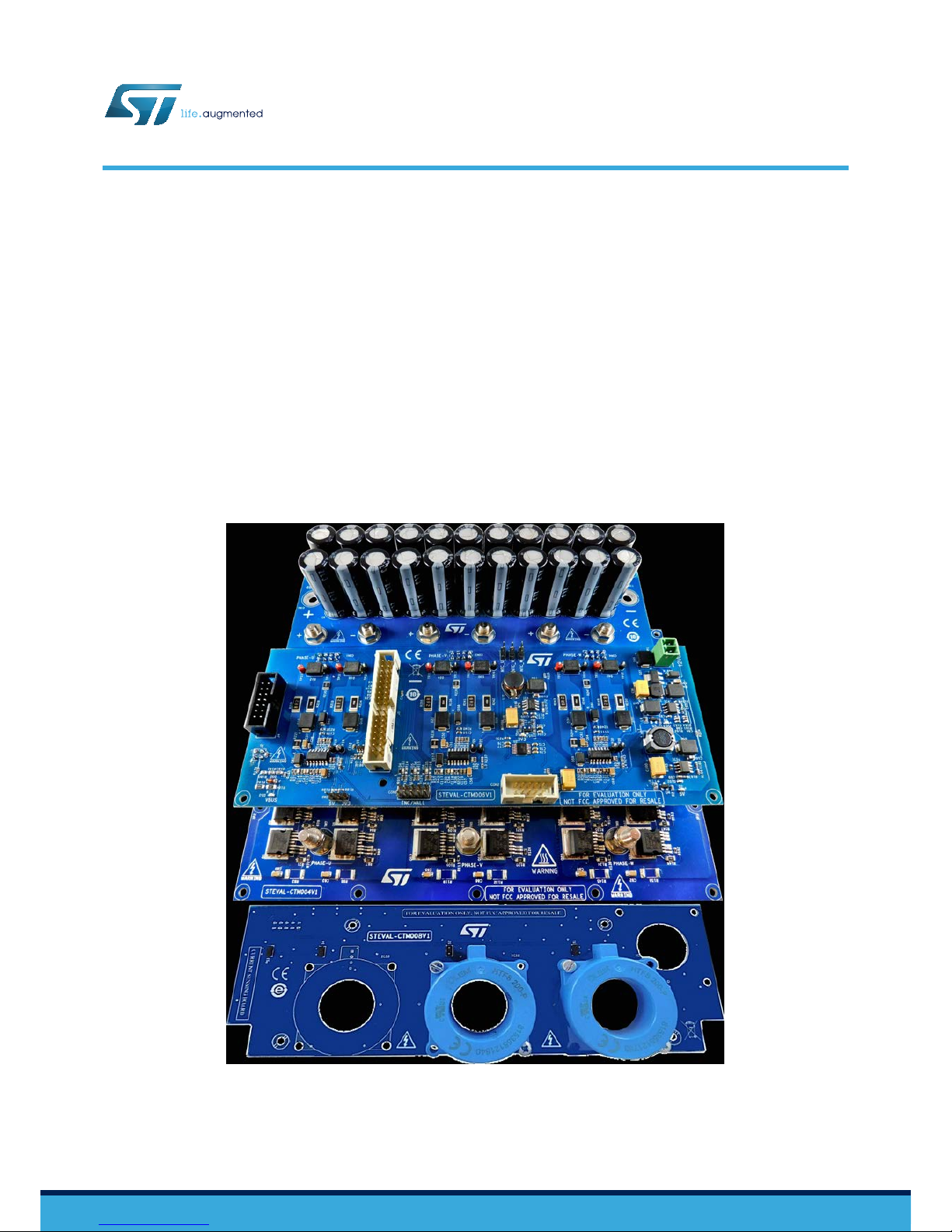
AL-CTM009V1 evaluation kit for motor control is designed to demonstrate the capabilities of ST Power MOSFETs
based on STripFET™ F7 technology. The 100V STripFET™ F7 devices (STH31*N10F7) are ideal for low voltage (up to 48 V),
high current applications such as forklifts, golf carts and power tool.
The STEVAL-CTM004V1 power board features an insulated metal substrate (IMS), NTCs for thermal protection and decoupling
gate resistors for each power MOSFET. The board mounts ST devices in the H²PAK-6 package.
The driver stage is an STEVAL-CTM006V1 board with L6491 high current capability gate drivers to drive the power MOSFETs
and integrated comparator for protections. The driver board includes the ST motor control connector, so you can interface the
STEVAL-CTM009V1 with any ST MCU control board suitable for motor control (not included in the kit).
The system also has an STEVAL-CTM005V1 bus link capacitor board and an STEVAL-CTM008V1 current sensing board.
Figure 1. STEVAL-CTM009V1 evaluation kit
5 kW low voltage high current inverter for industrial motor control applications
UM2458
User manual
UM2458 - Rev 1 - October 2018
For further information contact your local STMicroelectronics sales of
fice.
www.st.com
Page 2

1 Evaluation kit features
1.1 Electrical and functional characteristics
The kit features the following main characteristics:
•
Power board with insulated metal substrate (IMS) hosting 36 STH310N10F7 or STH315N10F7 power
MOSFETS in the H²PAK-6 (6x switch) package, designed also for automotive applications.
• High and low-side, high current capability (L6491) gate driver with integrated comparator for fast protection
and smart shutdown functions.
• Maximum power 5 kW at 48 V.
• Isolated current sensing, bus voltage and temperature monitoring.
1.2 Target applications
The STEVAL-CTM009V1 kit is designed for applications involving motor drives for electric traction, such as:
•
forklifts
• golf carts
• E-rickshaw
UM2458
UM2458 - Rev 1
page 2/40
Page 3

2 Safety and operating instructions
2.1 General terms
All operations involving transportation, installation and use, as well as maintenance, has to be carried out by
skilled technical personnel (national accident prevention rules must be observed). For the purpose of these basic
safety instructions, "skilled technical personnel" are considered as suitably qualified people who are familiar with
the installation, use, and maintenance of power electronic systems.
2.2 Intended use of evaluation kit
This evaluation kit is designed for demonstration purposes only and shall not be used for any commercial
purpose. The technical data, as well as information concerning power supply conditions, must be taken from the
relevant documentation and strictly observed.
2.3 Evaluation kit setup
• The evaluation kit must be set up in accordance with the specifications and the targeted application.
•
The board contains electro-statically sensitive components that are prone to damage through improper use.
Electrical components must not be mechanically damaged or destroyed.
• Avoid any contact with other electronic components.
• During the motor driving, converters must be protected against excessive strain. Do not bend or alter the
isolating distances any components during transportation or handling.
2.4 Electronic connections
Applicable national accident prevention rules must be followed when working on the main power supply with a
motor drive. The electrical installation must be completed in accordance with the appropriate requirements. A
system architecture which supplies power to the evaluation board must be equipped with additional control and
protective devices in accordance with the applicable safety requirements (e.g., compliance with technical
equipment and accident prevention rules).
UM2458
UM2458 - Rev 1
page 3/40
Page 4
3 Evaluation kit overview
The STEVAL-CTM009V1 evaluation kit is designed to let you evaluate STH31*N10F7 power MOSFETs, which
are driven by high and low-side, L6491 high current capability gate drivers. The system includes a bulk capacitor
board and a current sensing board.
The STEV
AL-CTM009V1 can be interfaced with any ST MCU evaluation board with embedded ST motor control
and ST FOC firmware library support.
This kit has been tested with the STEVAL-CTM001V1C (not included in this kit) control board of the STEVALHKI001V1 kit), which features an STM32F303RB 32-bit microcontroller.
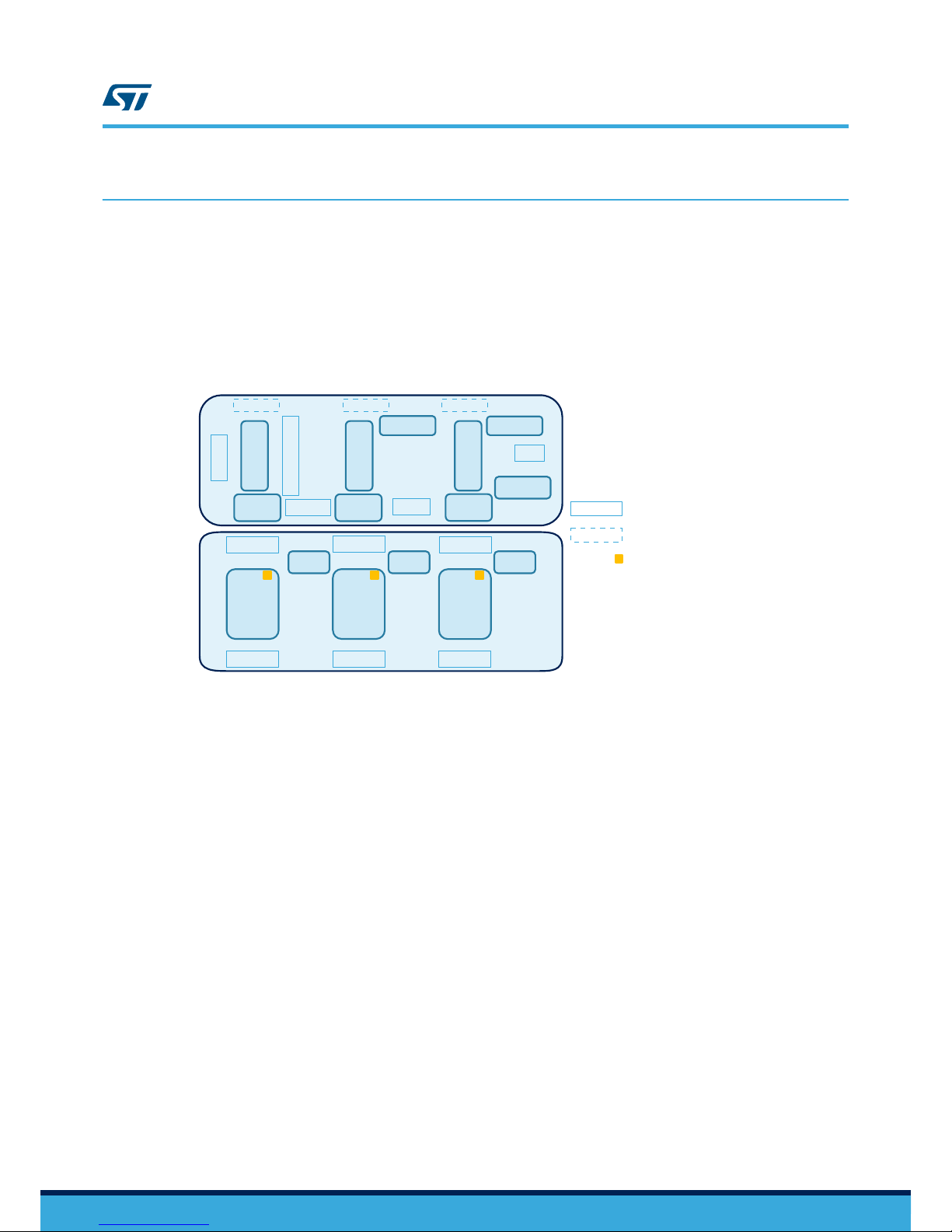
Figure 2. STEVAL-CTM009V1 block diagram
DRIVING STAGEPOWER STAGE
Not used
Motor Control
ICS
Ph_U driving
circuitry
Ph_V driving
circuitry
Ph_W driving
circuitry
Vin
L6491
driver
3V3 DC/DC
5V DC/DC
12V DC/DC
DRV->PW DRV->PW DRV->PW
L6491
driver
L6491
driver
ENC/HALL
PW->DRV
PW->DRV
PW>DRV
12x
STH315N10F7
in H
2
P
AK-6
-
Phase_U Phase_V Phase_W
Shunt
resistor
Shunt
resistor
Shunt
resistor
12x
STH315N10F7
in H
2
P
AK-6
12x
STH315N10F7
in H
2
P
AK-6
connector on top
connector on bottom
NTC
LEGEND
UM2458
Evaluation kit overview
UM2458 - Rev 1
page 4/40
Page 5
4 STEVAL-CTM004V1 power board
The STEVAL-CTM004V1 power board of the evaluation kit has 36 STH31*N10F7 N-channel Power MOSFETS in
the H²P
AK-6 package. A gate resistor is placed near each power MOSFET to eliminate parasitic oscillation. A
pull-down resistor between the gate and the source of each transistor helps to avoid capacitive coupling driving
the transistor and unwanted switch-on when gate is floating. A snubber RC circuit on each switch limits the rate of
voltage change during switching transitions to reduce electromagnetic interference (EMI) and losses.
two decoupling capacitors close to the switching power MOSFETs reduce ringing on the VDS and voltage stress
on the devices. The capacitors reduce voltage overshoot caused by abrupt current change in the parasitic
inductors in the circuit.
To monitor the temperature of the power board and provide over-temperature protection, three NTCs are placed
on the power board near the drain of one power MOSFET for each inverter leg.
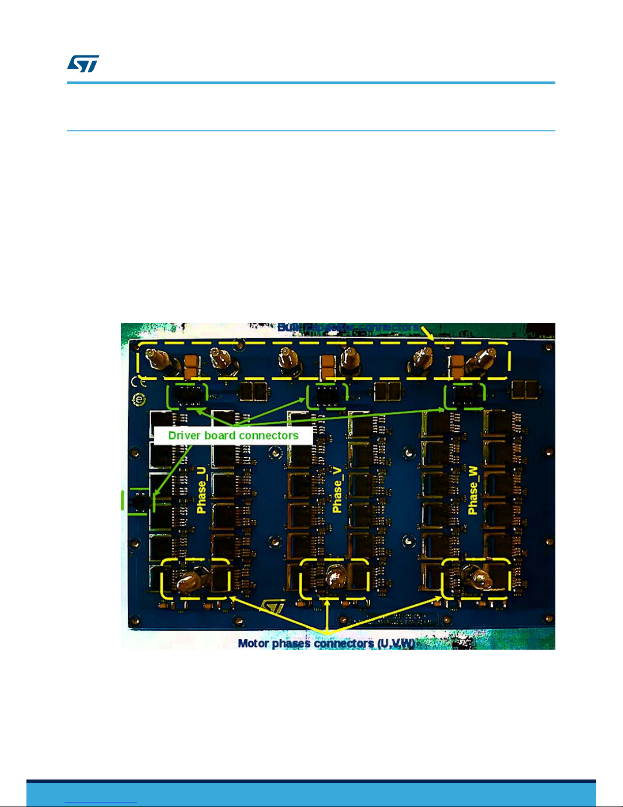
The power section also has connectors for the driver board, with CON5 (phase_U), CON6 (phase_V) and CON7
(phase_W) for gate driving and NTC sensing, and J3 for bus voltage. The board also hosts six towers near the
bulk capacitor board connection and three towers near the motor connection.
Figure 3. Main blocks of the STEVAL-CTM004V1 power board
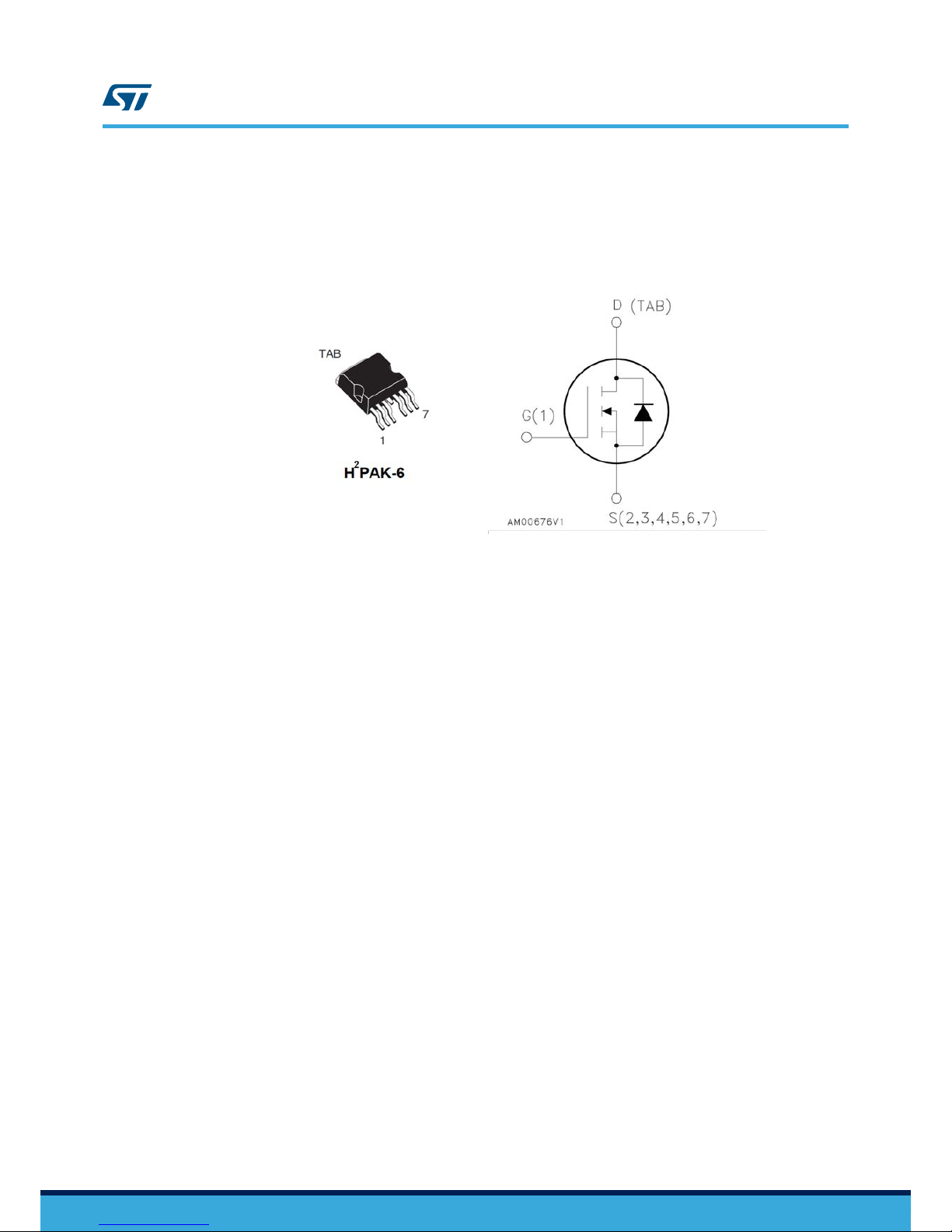
4.1 STH315N10F7 N-channel Power MOSFET characteristics
The N-channel Power MOSFETs use STripFET™ F7 technology with an enhanced trench gate structure for very
low on-state resistance and reduces internal capacitance and gate charge for faster and more ef
ficient switching.
The STH315N10F7 N-channel Power MOSFET has the following features:
• Designed for automotive applications and AEC-Q101 qualified
UM2458
STEVAL-CTM004V1 power board
UM2458 - Rev 1
page 5/40
Page 6
• Among the lowest R
DS(on)
on the market
•
Excellent figure of merit (FoM)
• Low C
rss/Ciss
ratio for EMI immunity
• High avalanche ruggedness
Figure 4. Package and internal schematic diagram
UM2458
STH315N10F7 N-channel Power MOSFET characteristics
UM2458 - Rev 1
page 6/40
Page 7
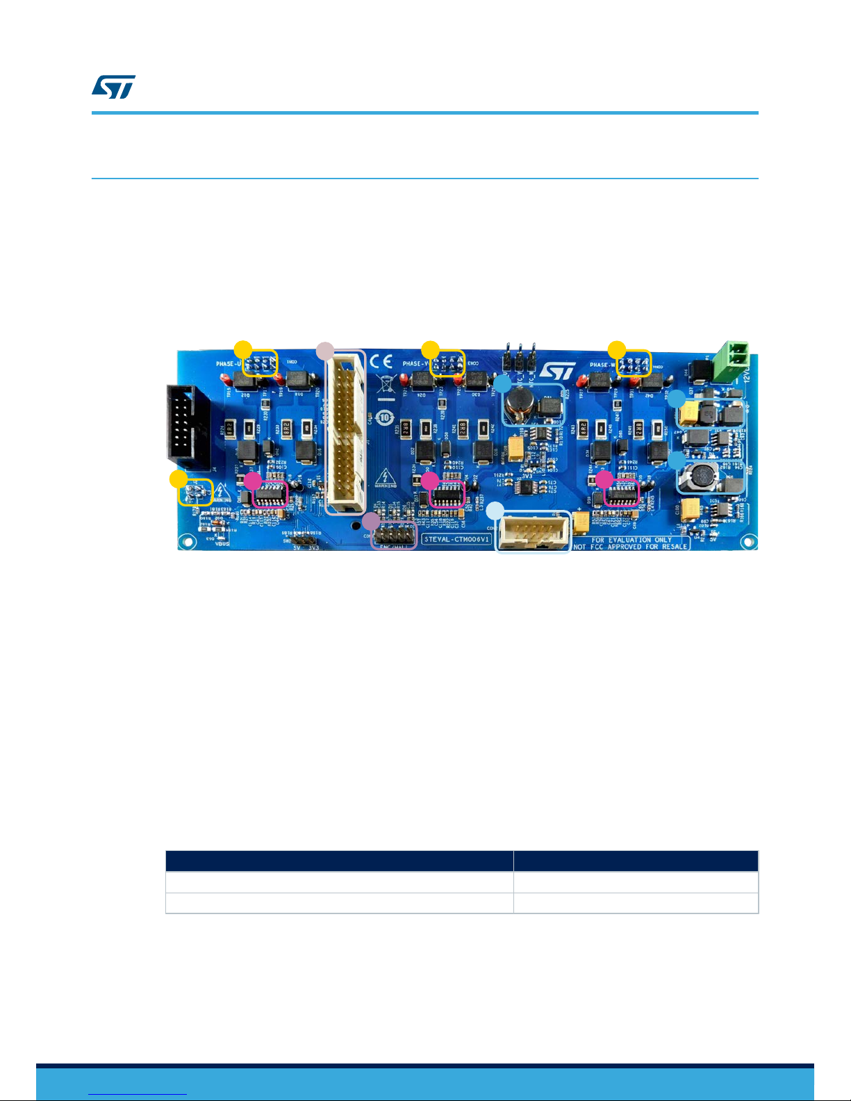
5 Driver board and control board overview
Figure 5. STEV
AL-CTM006V1 driver board functional blocks
1. connections to power board
2. motor control connector
3. ENC/HALL connector
4. ICS connector
5. L6491 drivers
6 3V3 DC/DC regulation
7. 5V DC/DC regulation
8. 12V DC/DC regulation
1
1 1
1
5
5
5
4
3
7
8
6
2
5.1 STEVAL-CTM006V1 driver board
5.1.1 Power supply section
The power supply section provides all the voltages necessary for the circuitry. The required input voltage is 8 to
36 V input, which is supplied through connector JP1.
The input voltage is then converted to the following voltage levels:
•
+12V for gate driver section (via an A7986 3 A step-down switching regulator)
• +5V and +3.3V for the control board (via an A6902 1 A switch step-down regulator)
5.1.2 Bus voltage monitoring
Bus voltage monitoring is implemented across an input voltage range of 5 to 75 V.
The following table shows the measured input voltage and the corresponding voltage level sent to the ADC input
of the STM32 microcontroller unit.
T
able 1. Input voltage bus and input signal to STM32 ADC channel
Input Voltage ADC input
48V 2.0V
75V (max value) 3.1V
5.1.3 Temperature monitor
Three NTCs are placed on the power section to provide temperature information, although only one NTC may be
chosen at a time. Close one of the three jumpers S1, S2 or S3 to read the temperature near the U, V or W phase,
respectively
. The microcontroller monitors processed signals to determine the temperature of the driver board and
manage any overload or over-temperature conditions.
To protect the hardware from excess temperature, a safe threshold is set in the STM32 FOC SDK software library.
UM2458
Driver board and control board overview
UM2458 - Rev 1
page 7/40
Page 8
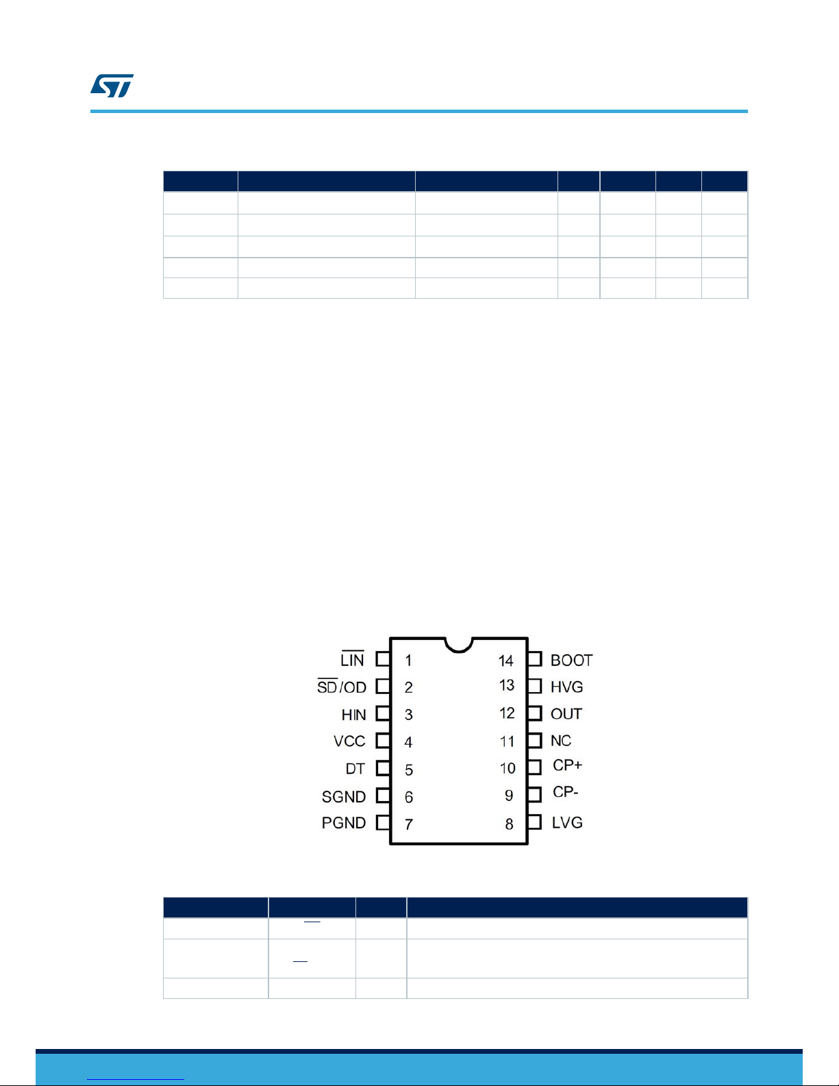
Table 2. NTC electrical characteristics
Symbol Parameter Test Condition Min Typ Max Unit
R
-40
Resistance T = -40°C - 105.7 - kΩ
R
25
Resistance T = 25°C - 4.7 - kΩ
R
100
Resistance T = 100°C - 0.426 - kΩ
B B- constant T = 25°C to 50°C - 3500 - -
T Operating temp range -40 125 °C
5.1.4 L6491 gate driver characteristics
The L6491 gate driver has the following main features:
•
dV/dt immunity ± 50 V/ns in full temperature range
• Driver current capability: 4 A source/sink
• Switching times 15 ns rise/fall with 1 nF load
• 3.3 V, 5 V TTL/CMOS inputs with hysteresis
• Integrated bootstrap diode
• Comparator for fault protections
• Smart shutdown function
• Adjustable deadtime
• Interlocking function
• Compact and simplified layout
• Bill of material reduction
• Effective fault protection
• Flexible, easy and fast design
For detailed information on the product, see the device datasheet.
Figure 6. L6491 gate driver pin-out
Table 3. Pin functions of L6491 gate driver
Pin number Pin name Type Function
1 LIN I Low-side driver logic input (active low)
2
SD / OD I/O
Shutdown logic input (active low)/open-drain
comparator output
3 HIN I High-side driver logic input (active high)
UM2458
UM2458 - Rev 1
page 8/40
Page 9

Pin number Pin name Type Function
4 VCC P Lower section supply voltage
5 DT I Deadtime setting
6 SGND P Signal ground
7 PGND P Power ground
8 LVG O Low-side driver output
9 CP- I Comparator negative input
10 CP+ I Comparator positive input
11 NC Not connected
12 OUT P High-side (floating) common voltage
13 HVG O High-side driver output
14 BOOT P Bootstrapped supply voltage
UM2458
UM2458 - Rev 1
page 9/40
Page 10
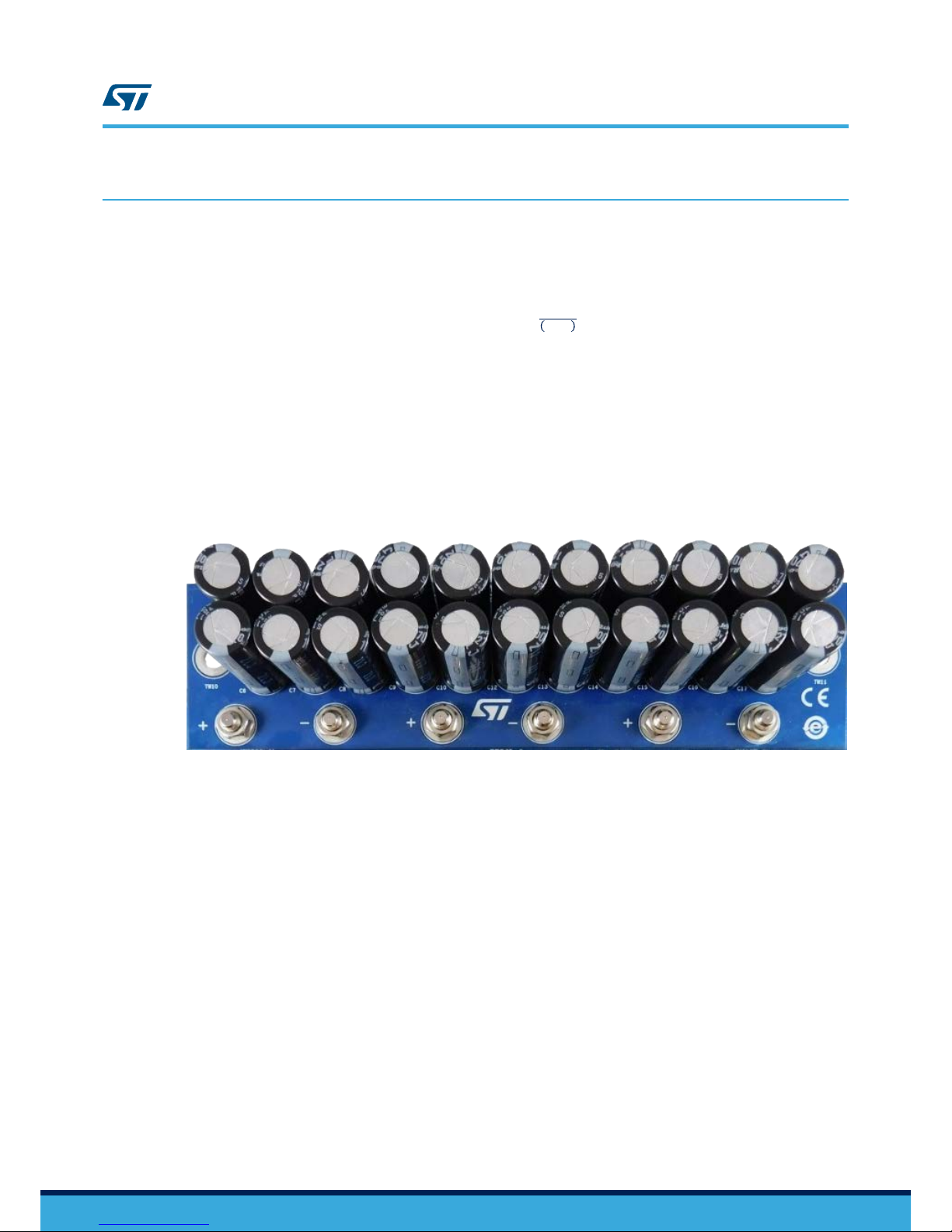
6 STEVAL-CTM005V1 bus link capacitor board
In EV inverter systems, bus link capacitors reduce ripple current and suppress voltage spikes caused by leakage
inductance and switching operations. These capacitors provide a low impedance path for the ripple currents
caused by output inductance load, the bus voltage and PWM frequency
.
The bus link capacitors must sustain a ripple current given by the following formula:
ΔI
0.5t
=
0.25 ×
V
b
us
f × L
Where:
•
ΔI
0.5t
is the maximum ripple current when duty cycle is 50%
• V
bus
is the bus voltage
• f is the switching frequency
• L is the load inductance.
For a very low inductance motor (worst case scenario), ΔI
0.5t
is about 48 A
RMS
(V
bus
= 52 V, f = 8 kHz and
L = 12 μH). If we add 10% to ΔI
0.5t
and choose electrolytic capacitors with a ripple current of 2.4 A, 22 electrolytic
capacitors are required. The resulting capacitance is about 6 mF, leading to a negligible ripple voltage on the bus.
Figure 7. STEVAL-CTM005V1 bus link capacitor board
6.1 STEVAL-CTM008V1 current sensing board
The STEVAL-CTM008V1 current sensing board is a general purpose board for motor control that can read up to
three phase motor currents and DC bus currents if four ICS are on-board. The board included in the kit hosts two
ICS to read two phase currents.
This sensing feature determines motor currents for digital control based on FOC algorithms. The sensors provide
high accuracy
, with 4 mV/A over a temperature range of -40 °C to +105 °C and a nominal current of 200 A
RMS
.
The internal reference voltage of the ICSs (according to their VCC) is generally used, but the reference voltage
can be overdriven by providing an external reference voltage through the J1 connector. A female to female flat
cable is used to connect CON2 on the driver board with J1 on the current sensing board.
The signals from the sensors center around 1.65 V (average value at zero current).
UM2458
STEVAL-CTM005V1 bus link capacitor board
UM2458 - Rev 1
page 10/40
Page 11
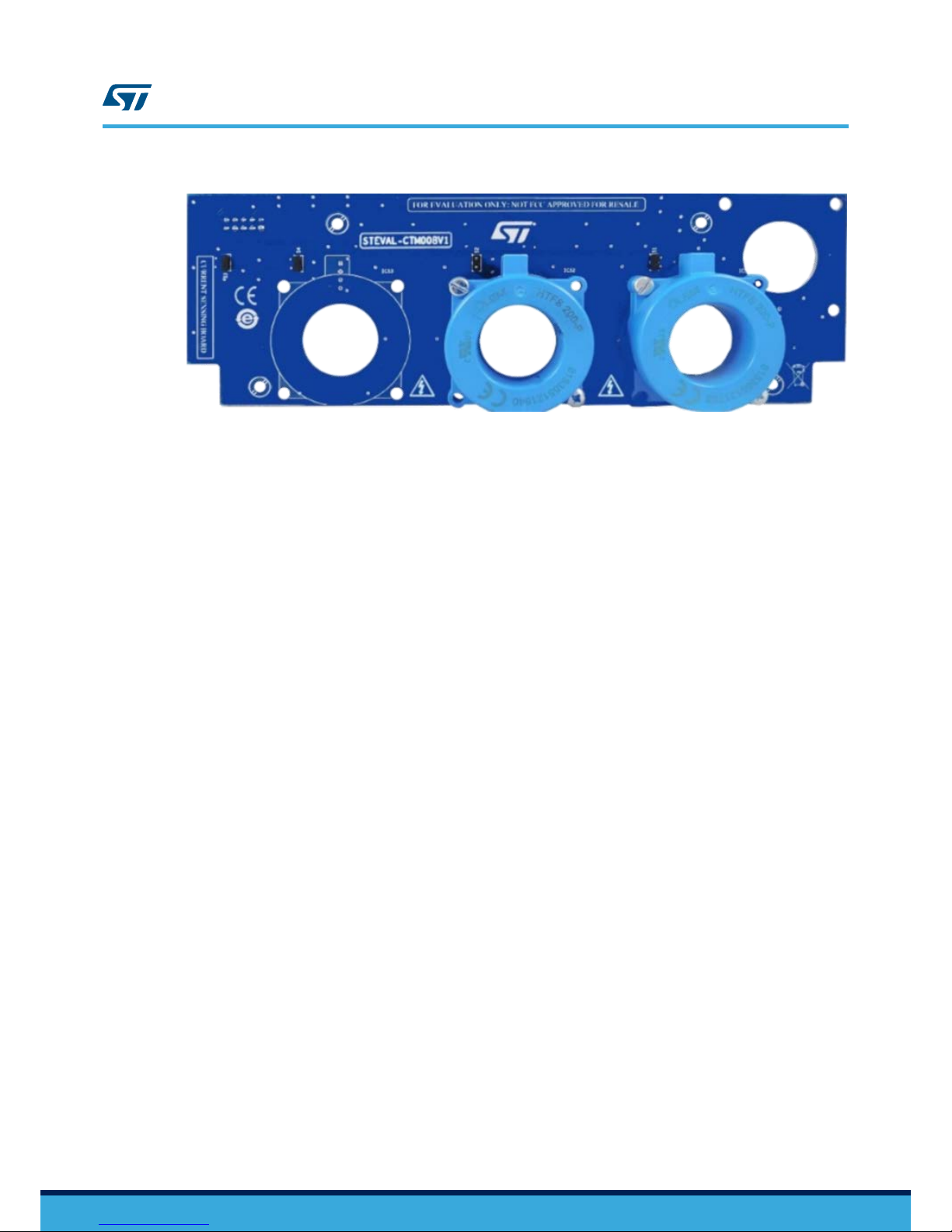
Figure 8. STEV
AL-CTM008V1 current sensing board
UM2458
STEVAL-CTM008V1 current sensing board
UM2458 - Rev 1
page 11/40
Page 12

7 How to set up the system
Follow the steps below to set up the evaluation kit.
Step 1. Mount the STEV
AL-CTM004V1 power board heatsink.
Use standard thermal interface material or a graphite sheet for high thermal conductivity
Step 2. Connect the STEVAL-CTM004V1 power board with the STEVAL-CTM006V1 driver board.
– use connectors CON5, CON6, CON7 and J3 on the STEVAL-CTM004V1 power board
– use connectors CON1, CON3, CON4 and J2 on the STEVAL-CTM006V1 driver board
Step 3. Connect the control board:
– If you use the STEVAL-CTM001V1C control board (not included in the kit):
◦ use connectors J1 and J4 on the STEVAL-CTM006V1 driver board
◦ use connectors CON3 and CON1 on the STEVAL-CTM001V1C control board.
– If you use a control board that is not the STEVAL-CTM001V1C:
◦ Use connector J1 on the driver board.
Step 4. Mount the STEVAL-CTM005V1 bus link capacitor board on the STEVAL-CTM004V1 power board
Step 5. Set up the STEVAL-CTM001V1C control board (optional, if present).
– close jumper SW5 in the default position (indicated near the switch)
– connect ST-LINK to the CON14 connector
– connect the USB to serial converter to the P2 with a serial cable DB9 female to female
Step 6. Set up the STEVAL-CTM006V1 driver board.
– close jumper S1, S2 or S3 to read one of the three NTCs on the power stage
– connect a 12 V DC power supply to the JP1 connector and turn on the power supply
Step 7. Connect the flat cable between CON2 on the STEVAL-CTM006V1 driver board and J1 on the STEVAL-
CTM008V1 current sensing board.
Step 8. Connect a 48 VDC power supply to the STEVAL-CTM006V1 driver board.
Step 9. Connect the phase motor cables to the STEVAL-CTM004V1 power board.
7.1 Connectors
In addition to the connector used for the supply voltage, the driving board has connectors to plug it to the power
board and the control board, and to receive external signals.
•
Connector for supply voltage: provided at JP1 (8 to 36 V).
• Connectors to the power board:
– CON1, CON3 and CON4: for power MOSFET driving and NTC sensing.
– J2: connector for DC bus voltage sensing (fpr undervoltage and overvoltage protection).
• Connectors to the control board
– J1: motor control connector, including signals like fault management, bus voltage monitoring, power
board temperature sensing and current sensing.
– J4: connector used for mechanical robustness when a control board (e.g., STEVAL-CTM001V1C, not
included in kit) is plugged but not electrically connected.
• Connectors for external signals
– CON8 (ENC/HALL connector): to receive external signals from Encoder/Hall sensors and provides
+3V3 or +5V supply voltages.
– CON2 (CURRENT SENSING connector): to receive current signals from the external current sensor
board and provide a +5V supply voltage.
UM2458
How to set up the system
UM2458 - Rev 1
page 12/40
Page 13

Figure 9. Current sensing connector (CON2 on driver board)
Table 4. Current sensing connector pinout
Pin number Pin name / Function
1 Ground
2 ADC_U
3 Ground
4 ADC_V
5 Ground
6 ADC_W
7 Ground
8 Not Connected
9 Ground
10 Vcc_ICS
Figure 10. 34-pin motor control connector (J1 on the driver board)
Table 5. Motor control connector pinout
Pin number Pin name / Function Pin number Pin name / Function
1 FAULT 18 Ground
2 Ground 19 ADC_W
3 PWM_U_H 20 Ground
4 Ground 21 Not connected
UM2458
Connectors
UM2458 - Rev 1
page 13/40
Page 14

Pin number Pin name / Function Pin number Pin name / Function
5 PWM_U_L 22 Not connected
6 Ground 23 Not connected
7 PWM_V_H 24 Not connected
8 Ground 25 5V
9 PWM_V_L 26 Heatsink temperature signal
10 Ground 27 Not connected
11 PWM_W_H 28 3.3V
12 Ground 29 Not connected
13 PWM_W_L 30 Ground
14 Bus voltage monitoring 31 Enc A/H1
15 ADC_U 32 Ground
16 Ground 33 Enc B/H2
17 ADC_V 34 Enc Z/H3
7.2 Signal LEDs
Table 6. LEDs Indicators on board
Name Color Description Location
D1 RED 3V3 STEVAL-CTM006V1
D2 RED 5V STEVAL-CTM006V1
D3 RED 12V STEVAL-CTM006V1
D53 RED 48V STEVAL-CTM004V1
7.3 Push buttons
Table 7. Push buttons
Name Description Location
SW6 STM32 microcontroller reset Control Board
SW7 User push-button Control Board
UM2458
Signal LEDs
UM2458 - Rev 1
page 14/40
Page 15

8 Firmware for STM32 PMSM FOC SDK
This evaluation kit is compatible with latest X-CUBE-MCSDK
- STM32 FOC firmware library, please visit the X-
CUBE-MCSDK web page on www.st.com for information and installation instructions.
8.1 Firmware for STM32 PMSM FOC SDK
You can use the ST Motor control workbench to customize the STM32 FOC library (installed together with the X-
CUBE-MCSDK package). The required parameters for the power stage of the STEVAL-CTM009V1 are given in
the following table.
Parameter Value Unit
Inrush current limiter disabled -
Dissipative brake disabled -
Bus voltage sensing Enabled -
R1 (Bus voltage sensing) 63.9 kΩ
R2 (Bus voltage sensing) 2.7 kΩ
Min. rated voltage 36 V
Max. rated voltage 60 V
Nominal voltage 48 V
Temperature sensing Enabled -
V0 761 mV
T0 25 °C
ΔV/ΔT 21 mV/°C
Max. working temperature on sensor 125 °C
Current sensing Enabled -
Current reading topology Two insulated current sensors -
ICS gain 0.004 V/A
Overcurrent protection disabled -
Power switches - switching frequency
12
(can be changed according the requirements)
kHz
Power switches - dead-time
2
(can be changed according the requirements)
µs
U,V,W driver
High side driving signal polarity
Active high -
U,V,W driver
Low side driving signal
Complemented from high side
disabled -
U,V,W driver
Low side driving signal
Polarity
Active low -
UM2458
Firmware for STM32 PMSM FOC SDK
UM2458 - Rev 1
page 15/40
Page 16

Parameter Value Unit
U,V,W driver
Force same values for U, V
, W driver
enabled -
U,V,W driver
Use STGAP1S gap drive
disabled -
UM2458
Firmware for STM32 PMSM FOC SDK
UM2458 - Rev 1
page 16/40
Page 17

9 Experimental measurements
The experimental results were obtained by testing the system at maximum power rating.
The power board was mounted with a heatsink (manuf.: ABL Components; manuf. order code: 159AB2000B; Rth:
0.36 °C/W
; dimensions: 200x160x40mm, or equivalent), using a thermal interface material with high thermal
conductivity (1300 W/mK) to form a natural convection cooling system.
A 48 V bus voltage was applied to drive a PMSM connected to a brake dynamometer.
The system was set at 5 kW output power to monitor the behavior of VGS, VDS, phase current and device
temperatures measured by an infrared thermo-camera.
Ch1: Ids; Ch2: Vgs HS; Ch3: Vds HS; Ch4: Vgs LS
Figure 11. Measured waveforms
The figure below shows the temperature of phase U devices after 40 minutes of continuous operation at full
power
. The devices operated in safe conditions and the temperature did not exceed the absolute max ratings. The
maximum measured temperature is about 105 °C.
UM2458
Experimental measurements
UM2458 - Rev 1
page 17/40
Page 18

Figure 12. Measured temperatures of U_phase Power MOSFET
s
The following table shows the MOSFET maximum, minimum and average temperature values.
T
able 8. Measured case temperatures of the STH315N10F7 power MOSFETs
Case Temperature [°C]
High Side Uphase devices Low Side Uphase devices
Q1 Q2 Q3 Q4 Q5 Q6 Q7 Q8 Q9 Q10 Q11 Q12
max. 99.5 99.8 100.4 101.2 102.4 101.5 98.5 101.9 103.4 104.5 104.3 104.9
min. 85.9 81.1 91.9 91.9 87.9 93.3
NA
(1)NA(1)
88.6 90.1 94.9 103.5
Average 94.6 91.6 98.8 96.2 96.7 97.4
NA
(1)
NA
(1)
94.5 96.7 99.9 101.9
1.
Not measured due to an obstacle along the measurement line
UM2458
Experimental measurements
UM2458 - Rev 1
page 18/40
Page 19

10 STEVAL-CTM0091V1 kit schematic diagrams
10.1 STEVAL-CTM004V1 schematic diagram
Figure 13. STEV
AL-CTM004V1 power board schematic
_
R82
R96
1
_
R176
2.2
U
GND
10k
Source
W
PW
_
_
2.2
R80
V
_
R155
_
Source
Source_
1
PW
W
HS
1
LS
_
_
2
_P
1
V
2
R150
R113
2.2
__V
1
1
D
Source
GATE
W
_
1
_
D
U
C86
PW
5 6 7
1
W
_
2
2
V
t
W
DC
_
V
_
V
2
_BUS-
1
2.2
U
0.001
_
1
Q35
_
DC
GATE
W
HS
N.M.
_
GATE
1
0.033uF
GATE
_
Q4
LS
_
_
_
R77
_
_
Q20
_
_
BUS-
2.2
PW
2 3
_LS
10k
5 6 7
PW
GATE
R142
_
23
Q21
PW
_
2
1uF
P
1
2.2
2.2
1
1
_
R118
R157
_
Battery
LS
23
R143
Q19L
1
2
t
_
_
2
10k
U_
C88
BUS+
R127
Q17
W
2
2.2
R132
NTC-
GATE
HS
NTC+
V
R71
U
V
0.033uF
GATE
DC
PHASE
_
_
1
1
R76
D
RT2
10k
Phase
W
Q13
GATE
W
RT3
_
2
LS
LS
2
BUS+
1
U
2.2
U
HS
2
HS
D
2
10k
_
5 6 7
GATE
D
GATE
W
2.2
U
PW
_
C83
10k
_
2.2
10k
P
LS
GATE
LS
GATE
_
_
Q11
_
1
V
LS
GND
HS
_
2.2
1
W
LS_
Q33
V__
GATE
HS
_
2 3
PHASE
1
2.2
_
1
_
VGATE
NTC+
Q30
TW7
10k
10k
_
_
GATE
U
W
V
1
_
1
R89
Out
LS
V
BUS+
_
10k
_
R158
GATE
_
_
W
R145
_
1
R84
D
_
2
_
1
2 3
Source
R131
_
V
2
PW
V
LS
R87
5 6 7
_
23
_
1
_
R135
Source
_
U
V
5 6 7
1
2
_
R128
1
_
Q26
2 3
23
10k
LS
_
LS
1
HS
HS
P
2
0.033uF
1
D
2
_U
Q36
_
HS
Phase
D
_
_
R81
_
D
_
_
V
1
_
2 3
10k
2.2
1
2
_
10k
D
5 6 7
PW
LS
TW8
BUS-
TW9
LS
10k
GATE
5 6 7
_
D
2
HS
RES
_NTC+
1
R133
Q15
LS
R152
1
_
_
2 3
BUS+
_
PW
5 6 7
10k
1
D
2
_
GATE
23
1
10k
10k
Q1
R112
GATE
_
D
_
BUS+
2
1
R1482.2
LS GATE
W
V
R174
_
_
GATE
4.7k
56 7
R74
NTC+
_
HS_
BUS-
HS
_
BUS-
1
5 6 7
GATE
V
2.2
1
_
GATE
Sense
D
R98
GATE
_
GATE
1
1
_
_
U
P
LS
U
0.001
0.001
_
R147
HS
BUS-
_
_ HS
U
W
PW
_
D
PW
1
R1382.2
1uF
R73
_
P
_
GATE
_HSOut
1
_
_
NTC+
DC
_
1uF
R109
W
1uF
2 3
R119
W
10k
_
U
_
R83
HS
W
1
2.2
U
4.7k
LS
_
11
GATE_
W
Q14
10k
10k
PW
D
RES
V
2.2
_
_
2.2
2
NTC-
R120
R175
PW_
_
12
D
0.033uF
HS
_
_
_
10k
V
56 7
Q34
2
1
DC
2
Q10
U
0.033uF
D
23
LS
_
R117
Source
NTC-
_
Q22
_
_
U
HS
_
C82
_
V
U
R177
Q12
2.2
Q27
R121
5 6 7
_
10k
LS_
2.2
PW
LS
2.2
4.7k
10k
R72
_
1
_
_
_
5 6 7
V
5 67
2 3
2
V
_
_
V
GATE_
_
1
1
GATE
+HV
R125
_
GATE
D
2.2
2 3
2
U
2.2
R153
0.001
2
_
C81
_
Source
R1242.2
V
1
R126
1
Q16
_
R97
V
R130
10k
R114
GATE
2
_
D
5 6 7
1
_
GATE
2
_
V
W
W
Out
GATE
_
PHASE
10k
10k
Sense
LS
HS
RES
2
1
2
_
_
1
V
R1222.2
2 3
PW
V
DC
_
R178
1
P
PW
1
D
U
_
10k
1
C80
C90
2.2
W
Q31
2.2
3
2 3
_
_
R137
R93
HS
PW
2 3
_
PW
_
P
_
0.001
R1072.2
_
2
Source
1
_
23
_
Sense
U
10k
1
GATE
Q25
_
D
R140
_
GATE
PW
2
1
56 7
1
2
_
V
2
DC_
Source
Source
U
W
GATE
R1362.2
_
D
_NTC+
D
Q3
1
D
P
2
Q7
R111
GATE
Phase
Source
Q2
2
2
RT1
1
1
_
S
_
1
V
_
D
1
_
1
R116
_
GND
t
R94
_
_
D
U
1
GND
D
_
Q28
U
_
R129
GATE
1
U
_
RES
2
5 67
_
R144
10k
P
_
C89
_
POWER
R108
D
10k
P
R78
NTC-
_
DC
5 6 7
HS
Source
2.2
_
2
HS
1uF
2
HS
_W
U
1
10k
Q6
R154
HS
HS
1
Source
2.2
56 7
1
V
Source
R85
_
DC
_
LS
W
GATE
LS
_
PW
2.2
Sense
PW
W
C87
2
_
_
_
NTC-
W
2
W
Q9
5 6 7
_
_
Source
2 3
U
V
W
RES
_
_
5 6 7
DC
V
1
Source
_
0.001
_
2
S
_
W
R156
_
W
_
R90
2
HS
U
R139
HS
_
C92
_HS_
R151
1
V
_
1
Q18
1
_
1
_
GATE
V
R173
2
5 67
LS
_
R88
Sense
_
_
1
_
GND__
2 3
2
P
_
GATE
D
NTC-
R95
GATE
GND
_
V
V
_
_
V
LS
_
BUS-
_
2.2
5 67
Sense
_
_
_
NTC-
1uF1
W
_
1
D
GATE
HS
NTC-
1
U
1
R146
_
NTC+
PW
10k
_
DC
2
R134
_
PW
RES
1
_
10k
C85
LS
HS
2
_
R149
_
_
R79
2
_
NTC+
2
_
1
_
_
Q29
U
_
D
R75
0.033uF
LS
W_
D
NTC+
U
U
2
_
Q23
_W
5 6 7
HS
DC
1
_
HS
2 3
R123
BUS-
R110
GATE
_
LS_
2 3
_
U
_
GATE
_
10k
_
PW
_
_
2
U
1
D
Q24
GATE
W
R141
2
Q32
10k
V
PW
1
U
_
2
GND
NTC-
V
Q5
DC
_
2.2
1
Q8
Source
2
W
U
_
R92
1
PW
L
W
GATE
GATE
10k
R115
DD
V
1
C91
2
3
3
2
3
2 32 32 3
2 3 23 2 32 3
3
3
5 6 7 5 6 75 6 7 5 6 75 6 7 5 6 7
5 6 7 5 6 75 65 6 75 75 6 7
7
6
UM2458
UM2458 - Rev 1
page 19/40
Page 20

10.2 STEVAL-CTM005V1 schematic diagram
Figure 14. STEV
AL-CTM005V1 capacitor board schematic
DC_BUS+_V
270µF
270µF
+
C14
+
C23
TW11
2
1
1
2
DC_BUS+_U
+
C12
2
1
270µF
1
C21
DC_BUS+_U
C13
++
270µF
C27
2
+
DC_BUS-
1
2
270µF
C20
2
C9
+
C18C10
1
1
DC_BUS-_V
270µF
1
2
++
PADs for High Current - 200A
C8
270µF
2
C19
+
C16
270µF
DC_BUS+
270µF
+
C24
DC_BUS-_U
2
1
270µF
270µF
1
C17
270µF
1
1
+
C15
DC_BUS+_V
2
+
C11
1
2
1
1
270µF
1
DC_BUS-
2
2
+
2
C22 C26
++
1
270µF
C7
DC_BUS-_W
+
270µF
2
1
2
+
270µF
2
+
DC_BUS+_W
2
270µF
DC_BUS-_V
1
TW10
+
2
DC_BUS+
1
DC_BUS+_W
270µF
C6
1
+
1
270µF
270µF
+
DC_BUS-_W
C25
270µF
270µF
1
2
2
2
1
DC_BUS-_U
10.3 STEVAL-CTM006V1 schematic diagrams
Figure 15. STEV
AL-CTM006V1 driver board schematic - main
4
LS_Gate_V_D
CH3_N
Driver Board
CH1_N
24
CON2
10
Enc Z/H3_D
GND_D
NTC+_W
6
1
1803426
1
4
7
21
CH1
POWER_GROUND_D
2
2
LS_Gate_W_D
LS_Source_W_D
2
NTC-_W
Temp.Monitoring
NTC+_W
ADC_U
8
1
CON3
4
HS_Source_W
HS_Source_U_D
HS_Source_W_D
NTC-_V
HS_Source_V_D
3
Temperature_Sensing_D
Enc A/H1_D
POWER_GND
NTC+_U
2
GND_D
J2
19
14
15
5
5
C4
NTC+_V
47µF
1
HS_Source_W_D
30
LS_Source_U
2
3
ADC_V
34
HS_Gate_U_D
LS_Gate_W
LS_Source_V_D
4
2
Iph_W
GND_D
GND_D
1
CON4
ADC_W
26
LS_Gate_W_D
6
1
CON1
CON4A
6
HS_Source_V
+
HS_Source_U_D
9
25
LS_Gate_V_D
1
Multipole Male connector
5
Distreleck 121637
09185346324
4
CH1_N
+Vin_D
+5V_D
+3V3_M
Iph_U
0.1µF
HS_Gate_U
1
FEMALE CONNECTOR - ON BOTTOM
2
Enc A/H1_D
HS_Gate_W_D
LS_Gate_V
NTC-_V
11
12
13
HS_Source_V_DHS_Gate_V_D
POWER_GROUND_D
18
20
8
7
1
DC_BUS_MONITOR_D
23
C5
14
Enc B/H2_D
JP1
Vcc_ICS
C3
Iph_V
LS_Gate_U_D
13
HS_Gate_V
10
7
FEMALE CONNECTOR - ON BOTTOM
FEMALE CONNECTOR- ON BOTTOM
FEMALE CONNECTOR- ON BOTTOM
8
C2
Enc B/H2_D
6
GND_D
2
120Ohm@100MHz
CH2_N
10
11
Vcc_ICS
22
0.1µF
2
1
Enc Z/H3_D
NTC+_ULS_Source_V_D
CH1
+5V_D
Temperature_Sensing_D
12
HS_Gate_V_D
HS_Source_U
6
LS_Source_W_D
NTC-_W
BKIN
DC_Bus_Monitor
2
2
LS_Source_U_D
NTC-_U
DC_BUS_MONITOR_D
7
NTC+_V
33
GND_D
BKIN_D
1
ADC_U
NTC-_U
2
4
LS_Source_V
CH2
6
1
3
LS_Gate_U
28
LS_Gate_U_D
ICS CONNECTCO1R
5
NTC+_U
NTC+_W
CH3
8
+HV_Battery_D
LS_Source_U_D
NTC-_U
CH3
1
CH3_N
0.1µF
+3V3_Micro_D
GND_D
7
29
CH2
+3V3_Micro_D
J1
17
1
LS_Source_W
L1
CH2_N
+HV_Battery_D
HS_Gate_W
4
HS_Gate_U_D
5
8
8V to 36V
NTC+_V
2
0.1µF
2
Driver Board
LS_Source_U_D
31
NTC-_W
9
5
HV_DC_BAT
3
J4
2
1
3
16
LS_Source_W_D
HS_Gate_W_D
GND_D
+5V_D
3
LS_Source_V_D
NTC-_V
ADC_V
ADC_W
+Vin_D
3
32
7
8
9
27
UM2458
STEVAL-CTM005V1 schematic diagram
UM2458 - Rev 1
page 20/40
Page 21

Figure 16. STEV
AL-CTM006V1 driver board schematic - sensing
D52
K
2
1
2
C33
+Vin_D
HS_IN_PWM
+3V3_D
HS_IN_PWM
-
+
R179
S1
Con2
2
NTC-_W
Con2
1
I_sense
2
Enc B/H2_D
D2
NTC+
0.0
CH2
C34
R184
1
3.9k
Source_HS
1
SD_1
0.1uF
2
Iph_U
R14NM
2
D1
CH2_N
A
0.0
1
+3V3_D
CH1_N
SD_3
Vin
GND_D
R1
Enc/Hall Connector Male
2
Iph_W
2
GND_D
1
GND_D
CH3_N
1
R180
Source_LS
2
K
D53
R186
39
+5V_D
POWER_GND
2
Drive_U
GND_D
HS_Source_W
LS_Gate_U
3
1
LS_IN_PWM
120Ohm@100MHz
Enc A/H1_D
0.0
1
20k
Enc A/H1_D
+5V_D
25°C= 0.8V
135 °C= 3.3V
2
+12V_D
2
120Ohm@100MHz
POWER_GND
GND_D
GND_Drive
2
Gate_LS
2
HS_Gate_U
GND_D
2
3
NTC+
A
2
1
+12V_D
GND_D
2
Iph_V
LS_IN_PWM
GND_P
NTC+_W
R12
1
1
POWER_GND
+12V_D
Enc A/H1_D
R4
2.7k
R9
10k
2
2
Vcc_ICS
BAT30KFILM
DC_Bus_Monitor
HV_DC_BAT
CH3
1
L2
K
GND_D
I_sense
Bus voltage sensing
GND_D
R13
A
3.3V
1
2
Iph_V
SD_1
OverCurrent Protection
3V3_D
S3
Source_LS
+5V_D
+3V3_M
3
K
1
20k
CH2
Iph_W
CH1
A
SD_2
20k
R182
+5V_D
10k
+3V3_D
I_sense
CH1_N
L3
Gate Driver
GND_D
HS_Gate_W
6
NTC+_V
HS_Source_U
CH3
Gate Driver
2
Gate_HS
R99
0.0
1
R3
CH1
CH2_N
0.1uF
Enc B/H2_D
+3V3_D
GND_P
+12V_D
R183
1
RS 687-8250
ON Semiconductor MMSZ4684T1G
NTC
HALL/ENCODER CONNECTOR
Gate_LS
10pF
C35
1
Overcurrent
POWER_GND
LS_Source_V
1
4.7k
5
8
10
1
L4
C113
1
SD/OD
SD_1
Source_HS
Iph_U
GND_P
0.0
1
NTC-_U
N.M.
2
+3V3_D
2
+12V_drive
+5V_Drive
+3V3_Drive
+3V3_Micro
1
BAT30KFILM
SD_3
NTC-
Source_LS
1
2
R187
GND_D
POWER_GND
2
HS_Source_V
D5
LS_Source_U
GND_D
K
C112
+3V3_D
CH1_N
2
2
9
Gate_HS
1
Enc Z/H3_D
Enc B/H2_D
D54
Gate Driver
GND_D
+12V_D
+3V3_D
R7
+5V_D
Iph_U
GND_D
1
R8
GND_D
R15NM
A
CH3_N
0.0
1
CH2_N
Drive_V
D4
NTC-
CON8
GND_D
Iph_W
U1
5
BAT30KFILM
NTC+_U
1
NTC-_V
0.0
2
R189
2
1
SD/OD
4.7k
3.57k
1
2
HS_IN_PWM
2
Enc Z/H3_D
1
Iph_V
S2
Con2
2
1
Ch3_N
R100.0
2
R101
D3
D6
1
2
LS_IN_PWM
+12V_D
+3V3_D
R100
+3V3_M
+5V_D
GND_D
HS_Gate_V
+5V_D
all resistor are 1% of tollerance
CH1
7
GND_D
820
+5V_D
10nF
SD_2
Gate_LS
SD_2
+12V_D
+3V3_D
Drive_W
R6
Source_HS
LS_Source_W
TSZ121IYLT
4
R181
+3V3_D
GND_D
120Ohm@100MHz
C28
+12V_D
SW2Con3
1
2
R2
Gate_HS
2
R185
GND_D
POWER_GND
LS_Gate_W
4
LS_Gate_V
1.33k
CH2
1
BKIN
Temp.Monitoring
1
10pF
2
4.7k
Driver Board Power Supply
R1880.0
1
R16NM
1
1.5k
+3V3_D
10pF
1
FAULT
+3V3_D
SD/OD
2.7V 500mW
SD_3
Enc Z/H3_D
CH3
GND_Drive
Driver Board Power Supply
2
+3V3_M
R11
0.0
2
UM2458
STEVAL-CTM006V1 schematic diagrams
UM2458 - Rev 1
page 21/40
Page 22

Figure 17. STEV
AL-CTM006V1 driver board schematic - gate drivers
LVG
Source_HS
D42
1
C72
R243
L6491D
A
100pFC120
1
2
fc=22.7kHz
GND_D
1
R58
1
R51
62k
HVG
13
2
1
GND_D
BOOT
14
1
+12V_D
DT
5
1
2
SD/OD
2
TP31
2
2
1
+3V3_D
1
5001
10uF
2
STPS5L60SY
LS_IN_PWM
1
0.0
6
2
4
Vcc
2.87k
Gate_HS
GND_P
+3V3_D
+12V_D
1
2
1
GND_P
SM15T12CAY
100kR59
2
1.5
2
TP30
A
D36
4.7k
8.2
1
D40
R248
LIN
1
0.1uF
15nF
9
CP-
5001
R245
1
C111
1
100pFC121
2
GND_P
R250
CP+
10
K
100
5001
C
1
1
5000
A
+3V3_D
TP28
2
2
2
PGND8LVG
N.C.
11
Expected 2.58V at 220Apk with LEM HTFS 200-P
2
1000pF
D59
R57
Source_LS
SD/OD
STPS5L60SY
IC9
C640.22uF
1
TP32
C74
K
100k
R223
GND_D
STTH102AY
HIN
3
TP27
0.22uF
D34
R249
0.1
R56
2
1
D60
1
C122
SM15T12CAY
2
8.2
5001
SGND
7
C65
1000pF
18k
1.5
2
5000
R62
GND_P
100
I_sense
Gate_LS
1
1
R247
1.87k
2
1
R53
C
C70
2
0.22uF
C631 µF
+3V3_D
STTH102AY
TP29
1
GND_P
+12V_D
10
R244
R246
1
R54
A
HS_IN_PWM
2
1
0.1uF
C67
2
1
C69
OUT
12
6.98k
1
LVG
Source_HS
D30
1
C59
R235
L6491D
A
100pFC117
1
2
fc=22.7kH
GND_D
1
R42
1
R35
62k
HVG
13
2
1
GND_D
BOOT
14
1
+12V_D
DT
5
1
2
SD/OD
2
TP25
2
2
1
+3V3_D
1
5001
10uF
2
STPS5L60SY
LS_IN_PWM
1
0.0
6
2
4
Vcc
2.87k
Gate_HS
GND_P
+3V3_D
+12V_D
1
2
1
GND_P
SM15T12CAY
100kR43
2
1.5
2
TP24
A
D24
4.7k
8.2
1
D28
R240
LIN
1
0.1uF
15nF
9
CP-
5001
R237
1
C110
1
100pFC118
2
GND_P
R242
CP+
10
K
100
5001
C
1
1
5000
A
+3V3_D
TP22
2
2
2
PGND8LVG
N.C.
11
z
Expected 2.58V at 220Apk with LEM HTFS 200-P
2
1000pF
D57
R41
Source_LS
SD/OD
STPS5L60SY
IC8
C510.22uF
1
TP26
C61
K
100k
R222
GND_D
STTH102AY
HIN
3
TP21
0.22uF
D22
R241
0.1
R40
2
1
D58
1
C119
SM15T12CAY
2
8.2
5001
SGND
7
C52
1000pF
18k
1.5
2
5000
R46
GND_P
100
I_sense
Gate_LS
1
1
R239
1.87k
2
1
R37
C
C57
2
0.22uF
C501 uF
+3V3_D
STTH102AY
TP23
1
GND_P
+12V_D
10
R236
R238
1
R38
A
HS_IN_PWM
2
1
0.1uF
C54
2
1
C56
OUT
12
6.98k
1
LVG
Source_HS
D42
1
C72
R243
L6491D
A
100pFC120
1
2
fc=22.7kH
GND_D
1
R58
1
R51
62k
HVG
13
2
1
GND_D
BOOT
14
1
+12V_D
DT
5
1
2
SD/OD
2
TP31
2
2
1
+3V3_D
1
5001
10uF
2
STPS5L60SY
LS_IN_PWM
1
0.0
6
2
4
Vcc
2.87k
Gate_HS
GND_P
+3V3_D
+12V_D
1
2
1
GND_P
SM15T12CAY
100kR59
2
1.5
2
TP30
A
D36
4.7k
8.2
1
D40
R248
LIN
1
0.1uF
15nF
9
CP-
5001
R245
1
C111
1
100pFC121
2
GND_P
R250
CP+
10
K
100
5001
C
1
1
5000
A
+3V3_D
TP28
2
2
2
PGND8LVG
N.C.
11
z
Expected 2.58V at 220Apk with LEM HTFS 200-P
2
1000pF
D59
R57
Source_LS
SD/OD
STPS5L60SY
IC9
C640.22uF
1
TP32
C74
K
100k
R223
GND_D
STTH102AY
HIN
3
TP27
0.22uF
D34
R249
0.1
R56
2
1
D60
1
C122
SM15T12CAY
2
8.2
5001
SGND
7
C65
1000pF
18k
1.5
2
5000
R62
GND_P
100
I_sense
Gate_LS
1
1
R247
1.87k
2
1
R53
C
C70
2
0.22uF
C631 uF
+3V3_D
STTH102AY
TP29
1
GND_P
+12V_D
10
R244
R246
1
R54
A
HS_IN_PWM
2
1
0.1uF
C67
2
1
C69
OUT
12
6.98k
1
U PHASE
V PHASE
W PHASE
UM2458
STEVAL-CTM006V1 schematic diagrams
UM2458 - Rev 1
page 22/40
Page 23

Figure 18. STEV
AL-CTM006V1 driver board schematic - overcurrent protection
U2C
3V3_D
4
SD_3
VD
VD
SD_1
VD
R251
2
C76
GND_D
2
0.1µF
GND_D
GND_D
1
C75
12
GND_D
13
11
GND_D
10
8
GND_D
1
1
VD
3V3_D
C77
7
U2A
0.1µF
9
2
6
MM74HC08MTCX
GND_D
SD_2
GND_D
1
2
0.1µF
U2D
5
0.0
1
MM74HC08MTCX
3
1
C79
MM74HC08MTCX
0.1µF
GND_D
C78
FAULT
GND_D
GND_D
2
14
2
14
MM74HC08MTCX
0.1µF
U2B
2
1
7
14
7
14
7
Figure 19. STEV
AL-CTM006V1 driver board schematic - power supply
C93
CS-
3
R163
GND_Drive
ESDA6V1LY
R160
VCC
R172
1
OUT
2
1.5k
2
STPS3L40SY
STPS5L60SY
L11
STN4NF06L
A
1
2
13k
C96
47uF
5.49k
1
+12V_drive
110k
1
BEAD Murata BLM18SG331TN1D
1
2
47uH
2
BEAD Murata BLM18SG331TN1D
L10
IC6
A6902D13TR
2
A
U3
C107
D50
2
R162
C94
1
2
K
1
+
2
BEAD Murata BLM18SG331TN1D
2
D46
R168
4
COMP
2
STPS3L40SY
CS+
2
2
1
C95
Vin
+3V3_Drive
2
0.1uF
+3V3_Micro
1
+5V_Drive
2
220
2
A
2
L6
2
GND
7
COMP
8
VCC
1
ESDA5V3LY
A
3.3uF
2
1
1
1
C97
47k
1k
R159
L5
ESDA14V2LY
1
15uH
2
CS+
15nF
0.0
Q37
6
2
9.1k
1
A
6
FSW
1
120pF
7GND 5FB
D48
2
R171
2
0.1
2
C101
CS-
3
1
R167
C99
1
SYNC
EN
3
0.1
10uF
C105
2
C104
1
D47
4.3k
U4
SM4T28AY
2
R165
+
C108
47uF
11
1
C100
47uF
1K1 2K2
A3
2
150pF
C102
0.1uF
C106
C98
11
1
K
7GND
EXP
9
15nF
STPS3L40SY
2
R170
1
U5
9.1k
L9
COMP
8
1
2
0.0
A3
2
4
12
2
2
1K1 2K2
A3
VCC
Vref
L7
68uH
2
3.3uF
+
1
2
D49
2
K
0.1uF0.1uF
5FB
4
9.1k
L12
2.49k
3V3/1A
5V/1A
12V/2A
C103
K
6 Vref
IC5
A6902D13TR
1K1 2K2
R224
FB
5
1
OUT
R164
2200pF
R225
OUT
1
2
1
8
IC4
A7986ATR
470pF
1
BEAD Murata BLM18SG700TN1D
1
R169
GND_Drive
1
STPS3L40SY
K
1
R166
L8
D51
1
R161
BEAD Murata BLM18SG331TN1D
UM2458
STEVAL-CTM006V1 schematic diagrams
UM2458 - Rev 1
page 23/40
Page 24

10.4 STEVAL-CTM008V1 schematic diagram
Figure 20. STEV
AL-CTM008V1 current sensing board schematic
Ibat
IPH_V
R5
TEST POINT
C5
47nF/10V
C4
ICS3
C8
JP
J1
TEST POINT
Ip
IPH_V
Vref
9
Vref
ICS1
Iph_W
IPH_U
IBAT
HTFS 200-P
1.8K
4
C2
JP
S1
0
8
TEST POINT
47nF/10V
S4
S2
Iph_V
3.6K
R7
C1
5
R3
47nF/10V
C3
TP4
1.8K
JP
7
3
Vref
C9
JP
+5V
Iph_U
1
HTFS 200-P
S3
Vref
1.8K
R1
C6
2
1
ICS4
Ip
47nF/10V
Vref
IPH_W
Out
3
3
Out
Out
2
1
+5V
0
male
0
2
4.7nF/10V
+5V
0
4
VCC
3
R4
TEST POINT
47nF/10V
0
3.6K
R6
ICS2
VCC
Ip
4
Vref
1
Ip
+Vcc
1
HTFS 200-P
47nF/10V
4
Out
1
1
C10
1.8K
TP1
0
IBAT
4
3.6K
R8
HTFS 200-P
TP2
+Vref
GND_C
0
TP3
IPH_W
2
+5V
4.7nF/10V
C12
CON10A
4.7nF/10V
1
C7
2
0
0
0
0
3.6K
+Vcc
0
47nF/10V4.7nF/10V
C11
10
6
R2
3
47nF/10V
IPH_U
1
UM2458
STEVAL-CTM008V1 schematic diagram
UM2458 - Rev 1
page 24/40
Page 25

11 STEVAL-CTM009V1 bill of materials
Table 9. STEV
AL-CTM009V1 evaluation kit bill of materials
Item Q.ty Ref. Part / Value Description Manufacturer Order code
1 1 -
STEVALCTM004V1
Power board ST
not available
separately
2 1 -
STEVALCTM005V1
Capacitor board ST
not available
separately
3 1 -
STEVALCTM006V1
Driver board ST
not available
separately
4 1 -
STEVALCTM008V1
Current sensing
board
ST
not available
separately
11.1 STEVAL-CTM004V1 bill of materials
Table 10. STEV
AL-CTM004V1 power board bill of materials
Item Q.ty Ref. Part / Value Description Manufacturer Order code
1 6
C80, C83, C85,
C88, C89, C92
0.033uF 1206
(3216 Metric)
250V
CAP CER 0.033UF
250V X7R 1206
TDK
Corporation
CGA5L3X7R2E333M1
60AA
2 6
C81, C82, C86,
C87, C90, C91
1uF 2220 (5750
Metric) 250V
CAP CER 1UF 250V
X7R 2220
TDK
Corporation
CGA9N3X7R2E105K2
30KA
3 3
CON5, CON6,
CON7
CON8
StripMale2X4SM
D
Double Strip Line
Male SMD 2X4 Pitch
2, 54
Molex. LLC 0015912080
4 1 J3
CON4A
StripMale2X2SM
D
double Strip Line
male smd 2X2 Pitch
2, 54mm
Molex. LLC 0015912040
5 36
Q1, Q2, Q3, Q4,
Q5, Q6, Q7, Q8,
Q9, Q10, Q1
1,
Q12, Q13, Q14,
Q15, Q16, Q17,
Q18, Q19, Q20,
Q21, Q22, Q23,
Q24, Q25, Q26,
Q27, Q28, Q29,
Q30, Q31, Q32,
Q33, Q34, Q35,
Q36
100V 180A
N-Ch Power
MOSFET H²PAK-6
ST
STH310N15F7-6
STH315N10F7-6
UM2458
STEVAL-CTM009V1 bill of materials
UM2458 - Rev 1
page 25/40
Page 26

Item Q.ty Ref. Part / Value Description Manufacturer Order code
6 36
R71, R72, R73,
R74, R75, R76,
R84, R85, R87,
R88, R89, R90,
R107, R108,
R109, R1
10,
R111, R112,
R120, R121,
R122, R123,
R124, R125,
R133, R134,
R135, R136,
R137, R138,
R146, R147,
R148, R149,
R150, R151
2.2 1206 (3216
Metric) 1/4
- - -
7 36
R77, R78, R79,
R80, R81, R82,
R92, R93, R94,
R95, R96, R97,
R1
13, R114,
R115, R116,
R117, R118,
R126, R127,
R128, R129,
R130, R131,
R139, R140,
R141, R142,
R143, R144,
R152, R153,
R154, R155,
R156, R157
10k 0603 (1608
Metric) 1/10w
RES SMD 10K OHM
1% 1/10W 0603
Yageo RC0603FR-0710KL
8 6
R83, R98, R119,
R132, R145,
R158
NM - - -
9 6
R173, R174,
R175, R176,
R177, R178
0.001 2818 7W
RES SMD 0.001
OHM 1% 7W 2818
Vishay Dale WSHM28181L000FEA
10 3 RT1, RT2, RT3
4.7k 0805 (2012
Metric)
NTC THERMISTOR
4.7K OHM 5% 0805
Murata
Electronics
North America
NCP21XM472J03RA
11 9
TW1, TW2,
TW3, TW4,
TW5, TW6,
TW7, TW8,
TW9, TW10,
TW1
1
Hexagonal
Tower M5x10mm
Male-Femal M5X10 RS PRO 806-6632
12 2 SP1, SP2 M3x10mm
Standoff, Steel, M3,
Hex Male-Female,
10 mm, W
A-SSTIE
Series
Wurth
Electronic
971 100 351
13 18
conic head
screw M3X8mm
M3x8mm
Machine Screw with
flat + spring lock
washer
Farnell 2494539
14 9+9+9 - M5
Nut + Washer +
shakeproof
RS
483-0546 + 482-7720
+ 526-833
UM2458
STEVAL-CTM004V1 bill of materials
UM2458 - Rev 1
page 26/40
Page 27

11.2 STEVAL-CTM005V1 bill of materials
Table 11. STEV
AL-CTM005V1 capacitor board bill of materials
Item Q.ty Ref. Part / Value Description Manufacturer Order code
15 22
C6, C7, C8, C9,
C10, C1
1, C12,
C13, C14, C15,
C16, C17, C18,
C19, C20, C21,
C22, C23, C24,
C25, C26, C27
270µF Radial,
Can 100V ±20%
CAP ALUM Rubycon 100ZLJ270M12.5X30
11.3 STEVAL-CTM006V1 bill of materials
Table 12. STEVAL-CTM006V1 driver board bill of materials
Item Q.ty Ref. Part / Value Description Manufacturer Order code
1 2 C1, C96 47µF 25V ±10% CAP TANT 2917
AVX
Corporation
TAJD476K025RNJ
2 2 C2, C4 0.1µF 25V ±10%
CAP, Ceramic, SMD,
0603
Kemet C0603C104K3RAC
3 19
C3, C5, C28,
C44, C57, C70,
C75, C76, C77,
C78, C79, C93,
C97, C103,
C104, C1
12,
C116, C119,
C122
0.1µF 50V ±10% CAP CER X7R 0603 KEMET C0603C104K5RACTU
4 1 C33 10pF 50V ±10% CAP CER X7R 0603
Murata
Electronics
North America
GRM188R71H103KA0
1D
5 2 C34, C35
10pF 50V
±0.5pF
CAP CER 10PF 50V
C0G 0603
TDK
Corporation
CGA3E2C0G1H100D0
80AD
6 3 C37, C50, C63 1 µF 50V ±10% CAP CER JB 1206
TDK
Corporation
C3216JB1H105K160A
A
7 9
C38, C48, C51,
C61, C64, C74,
C109, C1
10,
C111
0.22µF 50V
±10%
CAP CER X7R 0603
TDK
Corporation
CGA3E3X7R1H224K0
80AD
8 6
C39, C46, C52,
C59, C65, C72
1000pF 50V
±10%
CAP CER X7R 0603
AVX
Corporation
06035C102KAT2A
9 5
C41, C54, C67,
C99, C105
15nF 50V ±10% CAP CER X7R 0603
Murata
Electronics
North America
GRM188R71H153KA0
1D
10 4
C43, C56, C69,
C95
10µF 50V ±20% CAP CER X5R 1206
TDK
Corporation
CGA5L3X5R1H106M1
60AB
11 1 C94
2200pF 50V
±10%
CAP CER X7R 0603
TDK
Corporation
CGA3E2X7R1H222K0
80AD
12 1 C98 470pF 50V ±5% CAP CER C0G 0603
TDK
Corporation
CGA3E2C0G1H471J0
80AD
13 2 C100, C108 47µF 10V ±10% CAP TANT 2917
AVX
Corporation
TAJD476K010RNJ
UM2458
STEVAL-CTM005V1 bill of materials
UM2458 - Rev 1
page 27/40
Page 28

Item Q.ty Ref. Part / Value Description Manufacturer Order code
14 2 C101, C106 3.3µF 50V ±10% CAP CER X5R 0805
TDK
Corporation
C2012X5R1H335K125
AB
15 1 C102
150pF 100V
±5%
CAP CER C0G 0603
TDK
Corporation
CGA3E2C0G2A151J0
80AD
16 1 C107 120pF 50V ±5% CAP CER C0G 0603
TDK
Corporation
CGA3E2C0G1H121J0
80AD
17 1 C113 10nF 50V ±10% CAP CER X7R 0603
Murata
Electronics
North America
GRM188R71H103KA0
1D
18 6
C114, C115,
C1
17, C118,
C120, C121
100pF 50V ±5%
CAP CER C0G/NP0
0603
Murata
Electronics
North America
GRM1885C1H101JA0
1D
19 3
CON1, CON3,
CON4
CON8
Double Strip Line
Female 2X4 Pitch
2,54
Sullins
Connector
Solution
PPTC042LFBN-RC
20 1 CON2
ICS
CONNECT
OR
- HARTING 09185106324
21 1 CON8
Enc/Hall
Connector Male
Double Strip Line
Female 2X4 Pitch
2,54
Sullins
Connector
Solution
PPTC042LFBN-RC
22 4 D1, D2, D3, D53
1.6mmX0.8mm,3
0mA, 1.8V
DIO, Rectangle, Flat
T
op Red,
KINGBRIGHT KP-1608SRC-PRV
23 3 D4, D5, D6 30V 300mA
DIODE SCHOTTKY
SOD523
ST BAT30KFILM
24 7
D10, D16, D22,
D28, D34, D40,
D46
60V 5A
DIODE SCHOTTKY
SMC
ST STPS5L60SY
25 6
D12, D18, D24,
D30, D36, D42
10.2VWM
21.7VC
TVS DIODE SMC ST SM15T12CAY
26 4
D47, D48, D50,
D51
40V 3A
DIODE SCHOTTKY
SMC
ST STPS3L40SY
27 1 D49 400 W Automotive Transil ST SM4T28AY
28 1 D52 2.7V 500mW
DIODE ZENER
SOD80
Vishay
Semiconducto
r Diodes
Division
TZMB2V7-GS08
29 1 D54 3.3V 500mW
DIODE ZENER
SOD123
ON
SemiconductorMMSZ4684T1G
30 6
D57, D58, D59,
D60, D61, D62
200V 1A
DIODE GEN PURP
SMA
ST STTH102AY
31 1 IC4 3A
IC REG BUCK ADJ
8HSOP
ST A7986ATR
32 2 IC5, IC6 1A
IC REG BUCK ADJ
8SOIC
ST A6902D13TR
33 3 IC7, IC8, IC9 4A
IC GATE DVR
HIGH/LOW 14SOIC
ST L6491DTR
34 1 J1 34POS CONN HEADER T/H HARTING 09185346324
35 1 J2
CON4A 2X2
Pitch 2.54mm
double Strip Line
female
Sullins
Connector
Solution
PPTC022LFBN-RC
UM2458
STEVAL-CTM006V1 bill of materials
UM2458 - Rev 1
page 28/40
Page 29

Item Q.ty Ref. Part / Value Description Manufacturer Order code
36 1 J4 Multipole Male Connector
Sullins
Connector
Solution
SFH11-PBPC-D07-STBK
37 1 JP1
2-position vert
3.81mm
TERM BLOCK HDR
Phoenix
Contact
1803426
38 4 L1, L2, L3, L4
120Ω @
100MHz
FERRITE BEAD
0603 1LN
Wurth
Electronics
Inc.
742792625
39 1 L5
15µH 1.45A 125
MΩ ±20%
FIXED IND
Wurth
Electronics
Inc.
74404063150
40 1 L6 70Ω
FERRITE BEAD
0603 1LN
Murata
Electronics
North America
BLM18SG700TN1D
41 1 L7
68µH 1.9A 132
MΩ ±20%
FIXED IND SMD
Wurth
Electronics
Inc.
7447714680
42 4 L8, L9, L10, L12 330 Ω
FERRITE BEAD
0603 1LN
Murata
Electronics
North America
BLM18SG331TN1D
43 1 L11
47µH 1.8A 190
MΩ ±10%
FIXED IND SMD
Wurth
Electronics
Inc.
74456147
44 1 Q37 60V 4A
MOSFET N-CH
SOT
-223
ST STN4NF06L
45 1 R1
820Ω 1/10W
±1%
RES SMD 0603 Yageo RC0603FR-07820RL
46 1 R2
1.33k 1/10W
±1%
RES SMD 0603 Yageo RC0603FR-071K33L
47 1 R3
3.57k 1/10W
±1%
RES SMD 0603 Yageo RC0603FR-073K57L
48 16
R4, R6, R8, R9,
R10, R1
1, R12,
R13, R26, R42,
R58, R179,
R188, R224,
R225, R251
0.0Ω 1/10W
RES SMD JUMPER
0603
Yageo RC0603JR-070RL
49 2 R7, R163
1.5kΩ 1/10W
±1%
RES SMD 0603 Yageo RC0603FR-071K5L
50 3 R14, R15, R16 NM - Any -
51 6
R19, R35, R51,
R99, R100,
R101
4.7kΩ 1/10W
±1%
RES SMD 0603 Yageo RC0603FR-074K7L
52 6
R21, R22, R37,
R38, R53, R54
100Ω 1/10W
±1%
RES SMD 0603 Yageo RC0603FR-07100RP
53 3 R24, R40, R56
6.98kΩ 1/10W
±1%
RES SMD 0603 Yageo RC0603FR-076K98L
54 3 R25, R41, R57
1.87kΩ 1/10W
±1%
RES SMD 0603 Yageo RC0603FR-071K87L
55 3 R27, R43, R59
100kΩ 1/10W
±5%
RES SMD 0603 Yageo RC0603JR-07100KL
56 3 R30, R46, R62
2.87kΩ 1/10W
±1%
RES SMD 0603 Yageo RC0603FR-072K87L
UM2458
STEVAL-CTM006V1 bill of materials
UM2458 - Rev 1
page 29/40
Page 30

Item Q.ty Ref. Part / Value Description Manufacturer Order code
57 1 R159 1kΩ 1/10W ±1% RES SMD 0603 Yageo RC0603FR-071KL
58 1 R160
110kΩ 1/10W
±5%
RES SMD 0603 Yageo RC0603JR-07110KL
59 1 R161
47kΩ 1/10W
±1%
RES SMD 0603 Yageo RC0603FR-0747KL
60 1 R162
220Ω 1/10W
±1%
RES SMD0603 Yageo RC0603FR-07220RL
61 1 R164
2.49kΩ 1/10W
±1%
RES SMD 0603
Stackpole
Electronics
Inc.
RMCF0603FT2K49
62 2 R165, R169 0.1Ω 1/3W ±1% RES SMD 0603
Panasonic
Electronic
Components
ERJ-3BWFR100V
63 1 R166
13kΩ 1/10W
±1%
RES SMD 0603 Yageo RC0603FR-0713KL
64 3
R167, R170,
R171
9.1kΩ 1/10W
±1%
RES SMD 0603 Yageo RC0603FR-079K1L
65 1 R168
4.3kΩ 1/10W
±1%
RES SMD 0603 Yageo RC0603FR-074K3L
66 1 R172
5.49Ω 1/10W
±1%
RES SMD 0603 Yageo RC0603FR-075K49L
67 3
R180, R181,
R183
20kΩ 1/8W ±1% RES SMD0805 Yageo RC0805FR-0720KL
68 2 R182, R184 10kΩ 1/4W ±1% RES SMD 1206 Yageo RC1206FR-0710KL
69 1 R185
3.9kΩ 1/10W
±1%
RES SMD 0603 Yageo RC0603FR-073K9L
70 1 R186 39Ω 1/10W ±1% RES SMD 0603
Panasonic
Electronic
Components
ERJ-3EKF39R0V
71 1 R187
2.7kΩ 1/10W
±1%
RES SMD 0603 Yageo RC0603FR-072K7L
72 1 R189 N.M. ±1% - Any -
73 3
R222, R223,
R231
100k ±1% - Any -
74 6
R226, R233,
R235, R241,
R243, R249
8.2 ±1% - Any -
75 3
R227, R236,
R244
10Ω 1/2W ±1% RES SMD 1210
Stackpole
Electronics
Inc.
RMCF1210FT10R0
76 3
R228, R237,
R245
18k ±1% - Any -
77 6
R229, R234,
R238, R242,
R246, R250
1.5 ±1% - Any -
78 3
R230, R239,
R247
0.1 ±1% - Any -
79 3
R232, R240,
R248
62k ±1% - Any -
80 3 S1, S2, S3 Con2
CONN HEADER
2POS VER
T T/H
Amphenol FCI 77311-118-02LF
UM2458
STEVAL-CTM006V1 bill of materials
UM2458 - Rev 1
page 30/40
Page 31

Item Q.ty Ref. Part / Value Description Manufacturer Order code
81 1 SW2 Con3
SIL VERTICAL PC
T
AIL PIN HEADER
Harwin Inc. M20-9990345
82 6
TP15, TP19,
TP21, TP25,
TP27, TP31
5000
TEST POINT PC
MINI .040"D RED
Keystone
Electronics
5000
83 12
TP16, TP17,
TP18, TP20,
TP22, TP23,
TP24, TP26,
TP28, TP29,
TP30, TP32
5001
TEST POINT PC
MINI .040"D BLACK
Keystone
Electronics
5001
84 1 U1 400KHZ
IC OPAMP ZRODRFT SOT23-5
ST TSZ121IYLT
85 1 U2
IC GATE AND 4CH
2-INP 14-TSSOP
Fairchild/ON
SemiconductorMM74HC08MTCX
86 1 U3 12VWM 21VC
TVS DIODE
SOT23-3L
ST ESDA14V2LY
87 1 U4 5.2VWM 16VC
TVS DIODE
SOT23-3L
ST ESDA6V1LY
88 1 U5 3VWM 19VC
TVS DIODE
SOT23-3L
ST ESDA5V3LY
11.4 STEVAL-CTM008V1 bill of materials
Table 13. STEVAL-CTM008V1 sensing board bill of materials
Item Q.ty Ref. Part / Value Description Manufacturer Order code
1 4
C1,C4,C7,C9
ANY
4.7nF ,
smc0603, 25 V
,
10 %
CAP CER X7R 0603 any -
2 8
C2,C3,C5,C6,C8
,C10,C1
1,C12
ANY
47nF, 25 V, 10 % CAP CER X7R 0603 any -
3 2 ICS1,ICS2
CURRENT
SENSOR HALL
200A V
trasdulemHTFS400
P
LEM HTFS 200-P
4 1 ICS3 (NM)
CURRENT
SENSOR HALL
200A V
trasdulemHTFS400
P
LEM HTFS 200-P
5 1 ICS4 (NM)
CURRENT
SENSOR HALL
200A V
trasdulemHTFS400
P
LEM HTFS 200-P
6 4
TP1,TP2,TP3,TP
4
M3X20mm
Male_Femal,
mthole3
hex spacer richco htsb-m3-20-5-2
7 1 J1
10X2 pitch
2,54mm,
ampmode10
Connector male
Wurth_Elektro
nik
61201021621
8 4
R1,R3,R5,R7
ANY
3.6kΩ 1/10W 1
%
RES SMD 0603 any -
9 4
R2,R4,R6,R8
ANY
1.8kΩ, 1/10W 1
%
RES SMD 0603 any -
UM2458
STEVAL-CTM008V1 bill of materials
UM2458 - Rev 1
page 31/40
Page 32

Item Q.ty Ref. Part / Value Description Manufacturer Order code
10 1 Flat cable 150mm
10 Position Cable
Assembly
Rectangular Socket
to Socket
Harwin Inc. M50-9100542
11 4
S1,S2,S3,S4
ANY
2X2,54 mm +
Jumper
,
siptm2002
Strip line male any -
UM2458
STEVAL-CTM008V1 bill of materials
UM2458 - Rev 1
page 32/40
Page 33

12 PCB layouts
The STEVAL-CTM004V1 power board is built on an IMS mono layer with a copper thickness of 175 µm. The
board is designed for optimal thermal management under high current conditions.
Figure 21. STEV
AL-CTM004V1 power board layout
The STEVAL-CTM006V1 driver board is a 2-layer PCB, thickness 1.6 mm and copper thickness 70 µm.
UM2458
PCB layouts
UM2458 - Rev 1
page 33/40
Page 34

Figure 22. STEV
AL-CTM006V1 driver board layout
UM2458
PCB layouts
UM2458 - Rev 1
page 34/40
Page 35

Revision history
T
able 14. Document revision history
Date Version Changes
04-Oct-2018 1 Initial release.
UM2458
UM2458 - Rev 1
page 35/40
Page 36

Contents
1 Evaluation kit features .............................................................2
1.1 Electrical and functional characteristics ............................................2
1.2 T
arget applications .............................................................2
2 Safety and operating instructions ..................................................3
2.1 General terms .................................................................3
2.2 Intended use of evaluation kit ....................................................3
2.3 Evaluation kit setup.............................................................3
2.4 Electronic connections ..........................................................3
3 Evaluation kit overview ............................................................4
4 STEVAL-CTM004V1 power board...................................................5
4.1 STH315N10F7 N-channel Power MOSFET characteristics............................5
5 Driver board and control board overview...........................................7
5.1 STEVAL-CTM006V1 driver board .................................................7
5.1.1 Power supply section .....................................................7
5.1.2 Bus voltage monitoring ....................................................7
5.1.3 Temperature monitor......................................................7
5.1.4 L6491 gate driver characteristics.............................................8
6 STEVAL-CTM005V1 bus link capacitor board ......................................10
6.1 STEVAL-CTM008V1 current sensing board .......................................10
7 How to set up the system .........................................................12
7.1 Connectors...................................................................12
7.2 Signal LEDs ..................................................................14
7.3 Push buttons .................................................................14
8 Firmware for STM32 PMSM FOC SDK .............................................15
8.1 Firmware for STM32 PMSM FOC SDK ...........................................15
9 Experimental measurements......................................................17
10 STEVAL-CTM0091V1 kit schematic diagrams......................................19
10.1 STEVAL-CTM004V1 schematic diagram ..........................................19
10.2 STEVAL-CTM005V1 schematic diagram ..........................................19
UM2458
Contents
UM2458 - Rev 1
page 36/40
Page 37

10.3 STEV
AL-CTM006V1 schematic diagrams .........................................20
10.4 STEVAL-CTM008V1 schematic diagram ..........................................23
11 STEVAL-CTM009V1 kit bill of materials............................................25
11.1 STEVAL-CTM004V1 bill of materials .............................................25
11.2 STEVAL-CTM005V1 bill of materials .............................................26
11.3 STEVAL-CTM006V1 bill of materials .............................................27
11.4 STEVAL-CTM008V1 bill of materials .............................................31
12 PCB layouts ......................................................................33
Revision history .......................................................................35
UM2458
Contents
UM2458 - Rev 1
page 37/40
Page 38

List of figures
Figure 1. STEV
AL-CTM009V1 evaluation kit ......................................................1
Figure 2. STEVAL-CTM009V1 block diagram......................................................4
Figure 3. Main blocks of the STEVAL-CTM004V1 power board .........................................5
Figure 4. Package and internal schematic diagram ..................................................6
Figure 5. STEVAL-CTM006V1 driver board functional blocks ...........................................7
Figure 6. L6491 gate driver pin-out .............................................................8
Figure 7. STEVAL-CTM005V1 bus link capacitor board.............................................. 10
Figure 8. STEVAL-CTM008V1 current sensing board ............................................... 11
Figure 9. Current sensing connector (CON2 on driver board) ..........................................13
Figure 10. 34-pin motor control connector (J1 on the driver board) .......................................13
Figure 11. Measured waveforms .............................................................. 17
Figure 12. Measured temperatures of U_phase Power MOSFETs ....................................... 18
Figure 13. STEVAL-CTM004V1 power board schematic ..............................................19
Figure 14. STEVAL-CTM005V1 capacitor board schematic ............................................ 20
Figure 15. STEVAL-CTM006V1 driver board schematic - main.......................................... 20
Figure 16. STEVAL-CTM006V1 driver board schematic - sensing........................................ 21
Figure 17. STEVAL-CTM006V1 driver board schematic - gate drivers ..................................... 22
Figure 18. STEVAL-CTM006V1 driver board schematic - overcurrent protection.............................. 23
Figure 19. STEVAL-CTM006V1 driver board schematic - power supply .................................... 23
Figure 20. STEVAL-CTM008V1 current sensing board schematic........................................ 24
Figure 21. STEVAL-CTM004V1 power board layout ................................................. 33
Figure 22. STEVAL-CTM006V1 driver board layout ................................................. 34
UM2458
List of figures
UM2458 - Rev 1
page 38/40
Page 39

List of tables
T
able 1. Input voltage bus and input signal to STM32 ADC channel .......................................7
Table 2. NTC electrical characteristics ...........................................................8
Table 3. Pin functions of L6491 gate driver ........................................................8
Table 4. Current sensing connector pinout........................................................ 13
Table 5. Motor control connector pinout.......................................................... 13
Table 6. LEDs Indicators on board .............................................................14
Table 7. Push buttons ...................................................................... 14
Table 8. Measured case temperatures of the STH315N10F7 power MOSFETs ..............................18
Table 9. STEVAL-CTM009V1 evaluation kit bill of materials............................................ 25
Table 10. STEVAL-CTM004V1 power board bill of materials ............................................ 25
Table 11. STEVAL-CTM005V1 capacitor board bill of materials .......................................... 27
Table 12. STEVAL-CTM006V1 driver board bill of materials.............................................27
Table 13. STEVAL-CTM008V1 sensing board bill of materials ........................................... 31
Table 14. Document revision history ............................................................. 35
UM2458
List of tables
UM2458 - Rev 1
page 39/40
Page 40

IMPORTANT NOTICE – PLEASE READ CAREFULLY
STMicroelectronics NV and its subsidiaries (“ST”) reserve the right to make changes, corrections, enhancements, modifications, and improvements to ST
products and/or to this document at any time without notice. Purchasers should obtain the latest relevant information on ST products before placing orders. ST
products are sold pursuant to ST’
s terms and conditions of sale in place at the time of order acknowledgement.
Purchasers are solely responsible for the choice, selection, and use of ST products and ST assumes no liability for application assistance or the design of
Purchasers’ products.
No license, express or implied, to any intellectual property right is granted by ST herein.
Resale of ST products with provisions different from the information set forth herein shall void any warranty granted by ST for such product.
ST and the ST logo are trademarks of ST. All other product or service names are the property of their respective owners.
Information in this document supersedes and replaces information previously supplied in any prior versions of this document.
© 2018 STMicroelectronics – All rights reserved
UM2458
UM2458 - Rev 1
page 40/40
 Loading...