

UM2438
User manual
Predictive maintenance reference kit with sensors and IO-Link capability
Introduction
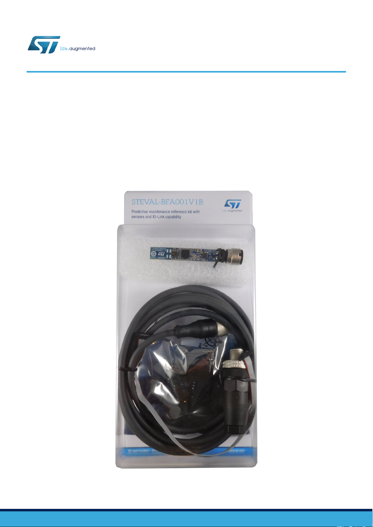
The STEVAL-BFA001V1B
vibration, environmental and acoustic algorithms for condition monitoring and predictive maintenance applications and can be
used as a reference to base your own solutions on our hardware and software designs.
The kit is based on the STEVAL-IDP005V1 high performance industrial sensor platform featuring a compact design that is
especially suitable for monitoring motors, pumps and fans.
reference kit for condition monitoring and predictive maintenance lets you evaluate embedded
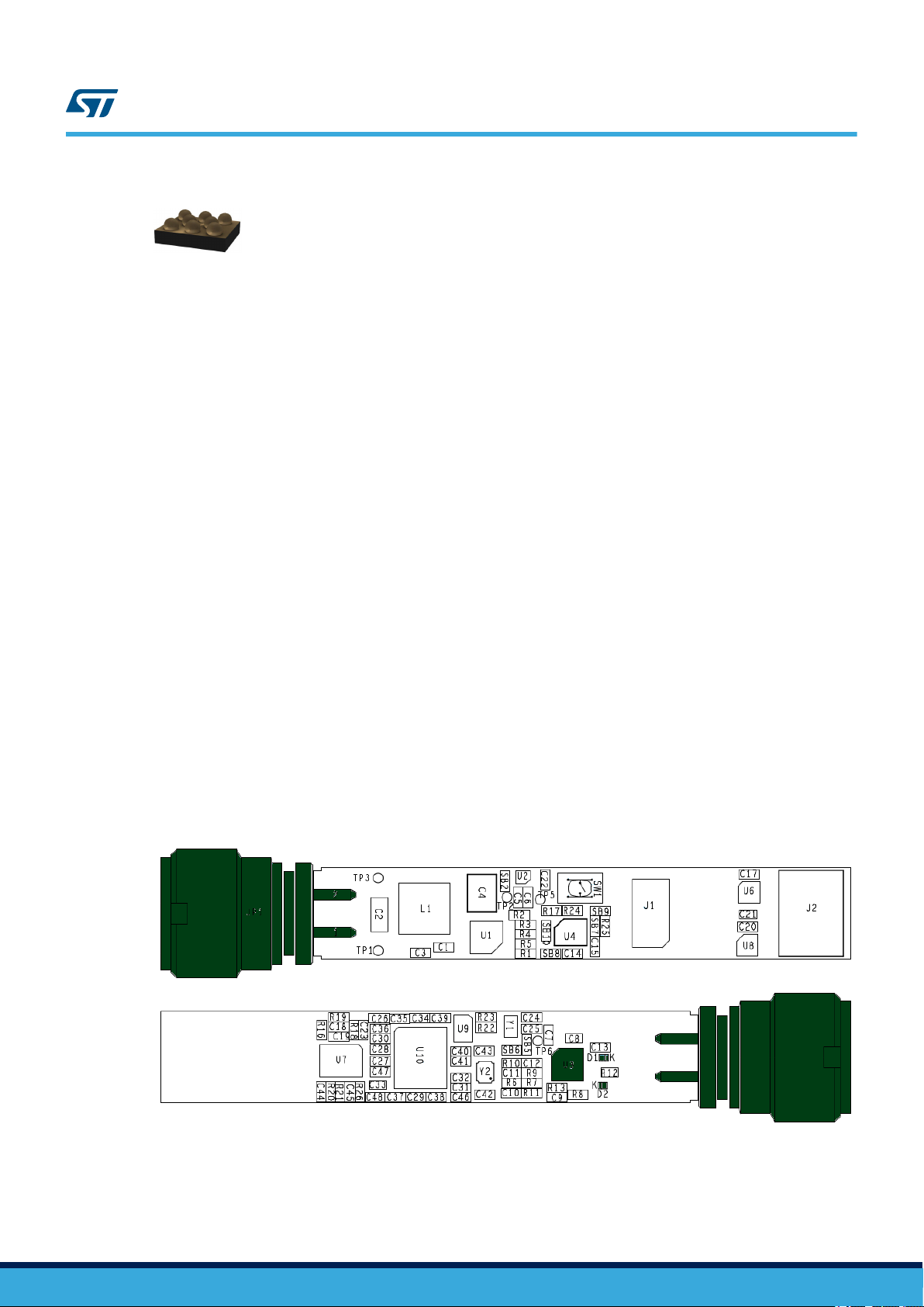
Figure 1. STEVAL-BFA001V1B predictive maintenance reference kit
UM2438 - Rev 2 - March 2019
For further information contact your local STMicroelectronics sales office.
www.st.com

1 Overview
The main board in the kit is the STEVAL-IDP005V1 sensor platform, which features a high end ARM® Cortex®-M4
32-bit microcontroller running the processing and analysis firmware for the following on-board sensors:
• an iNEMO 6DoF accelerometer and gyroscope
• a barometric pressure sensor
a relative humidity and temperature sensor
•
• a digital microphone
The sensor platform comes complete with EEPROM for data Storage, an IO-Link PHY device and power
management based on a step-down switching regulator and LDO regulator.
The firmware includes all the necessary drivers, libraries, application and demonstration software and utilities to
deliver the following functionality:
• algorithms for advanced time and frequency domain vibration analysis
• environmental (pressure, humidity and temperature) monitoring
• audio algorithms for acoustic emission (AE)
• condition monitoring and predictive maintenance demonstration software
• a GUI to help you set up monitoring environments and plot incoming data
Sensor data results can be transmitted through one of the following serial communication channels:
1. IO-Link (stack is not included in the FW): connect with an external STEVAL-IDP004V1 IO-Link master multiport evaluation board and use one of the firmware applications or the GUI bundled in the firmware package
to display sensor data and send query commands.
2. UART: display the data using a common terminal emulator like TeraTerm, through the UART communication
channel.
UM2438
Overview
RELATED LINKS
Visit the STEVAL-BFA001V1B web page for the most up to date resources and reference material
UM2438 - Rev 2
page 2/67
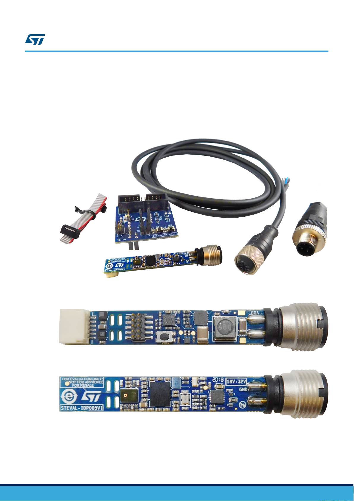
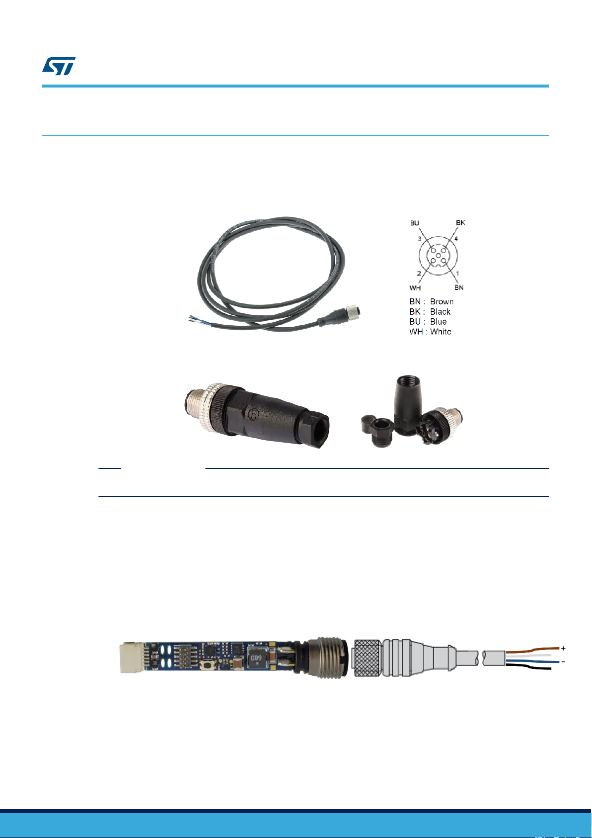
1.1 Package components
One reference design board (10 x 50 mm) - STEVAL-IDP005V1.
•
• One adapter for ST-LINK programming and debugging tool - STEVAL-UKI001V1.
• One 0.050” 10-pin flat cable.
• One 4-pole cable with M12 female connector.
• One 4-pole mount M12 connector plug, with male contacts.
UM2438
Package components
Figure 2. STEVAL-BFA001V1B package contents
1.2 System requirements
The STEVAL-IDP005V1 is already programmed with Condition Monitoring firmware. To run the demo, you need
the following items:
• A Windows™ (version 7 or higher) PC with a serial line terminal application like Putty.
• A USB type A to mini B male cable.
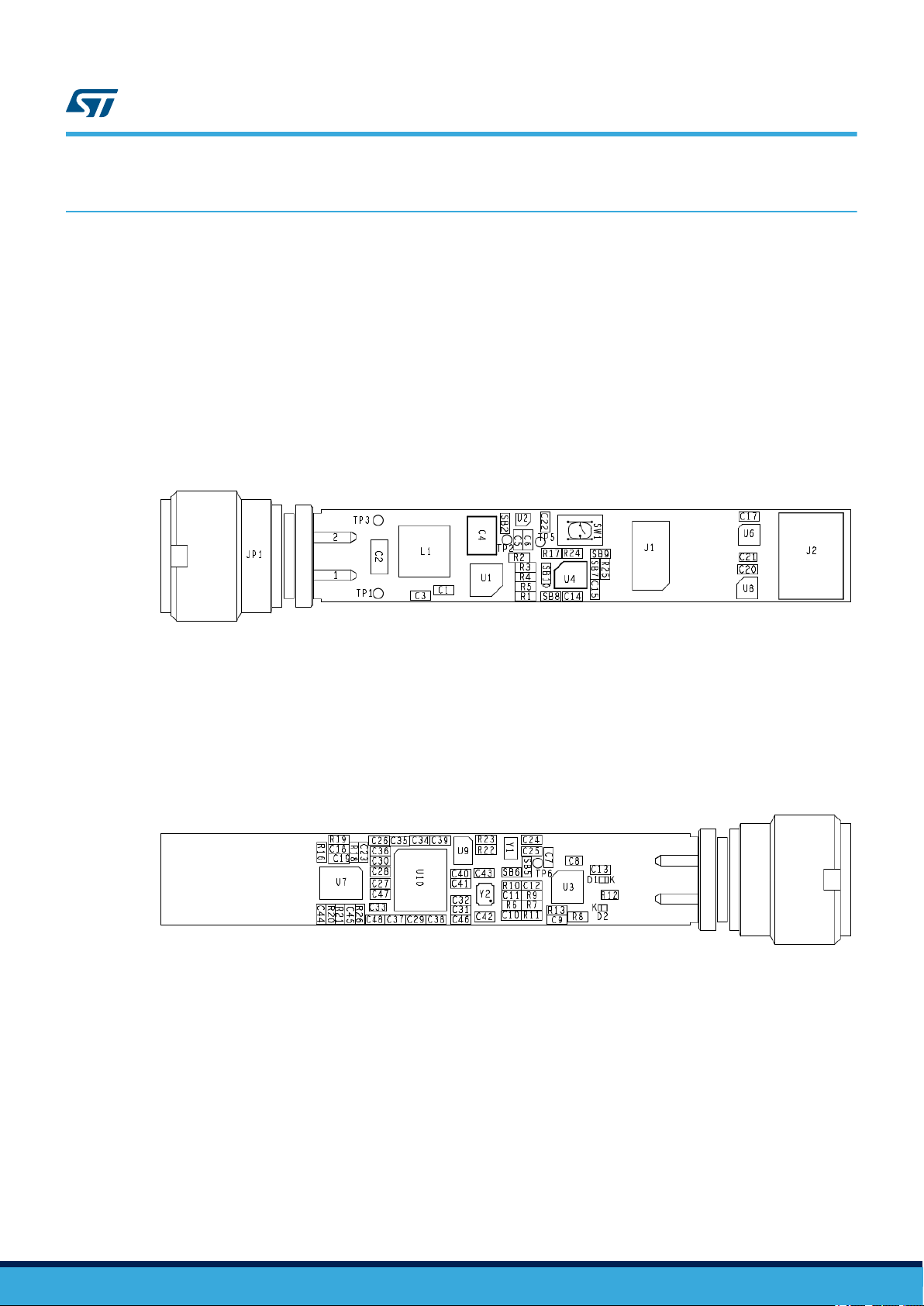
Figure 3. STEVAL-IDP005V1 board - top
Figure 4. STEVAL-IDP005V1 board - bottom
UM2438 - Rev 2
page 3/67

• A generic power supply (range 18 to 32 V).
•
An STM32 Nucleo 64 board with ST
-LINK V2.1 in-circuit debugger/programmer
To develop your own project, you will also need the following items:
• A Windows™ (version 7 or higher) PC with IAR, KEIL or System Workbench for STM32 firmware
development environment.
• Microsoft.NET Framework 4.5 or higher (for the GUI only).
• ST-LINK utility for binary firmware download (find the latest embedded software version on www.st.com).
1.3 How to run the demo supplied with the firmware
UM2438
How to run the demo supplied with the firmware
.
To run the demo, you must first unpack the STEV
AL-BFA001V1B
kit.
Follow the steps below to run the condition monitoring demonstration firmware (STSW-BFA001V1\Projects
\Demonstrations\Condition_Monitoring\CondMonitor_SRV) loaded on the STEVAL-IDP005V1 evaluation board:
Step 1. Plug the STEVAL-UKI001V1 onto the Nucleo board.
Step 2. Connect the STEVAL-UKI001V1 plus Nucleo board assembly to the STEVAL-IDP005V1.
Step 3. Supply power
Step 4. Connect the ST-LINK/V2-1 (on the STM32-NUCLEO 64 board) to the PC through the USB Type-A
Male to Type-B mini cable
Step 5. Open and configure your terminal emulator.
Set the following parameters:
– Name: COM Port name
– Baud Rate: 230400
– Data:8
– Parity: None
– Stop Bit: One
– Flow Control: None
Step 6. Push the Reset button on the STEVAL-UKI001V1 (or STEVAL-IDP005V1).
Step 7. Insert the new parameters and/or press ENTER, then press [Y] and [Enter] to start monitoring.
RELATED LINKS
4 How to supply power to the STEVAL-IDP005V1 board on page 15
5.1 Connection through an ST-LINK/V2-1
7.1 Outputs for the acoustic analysis project on page 29
on page 17
UM2438 - Rev 2
page 4/67
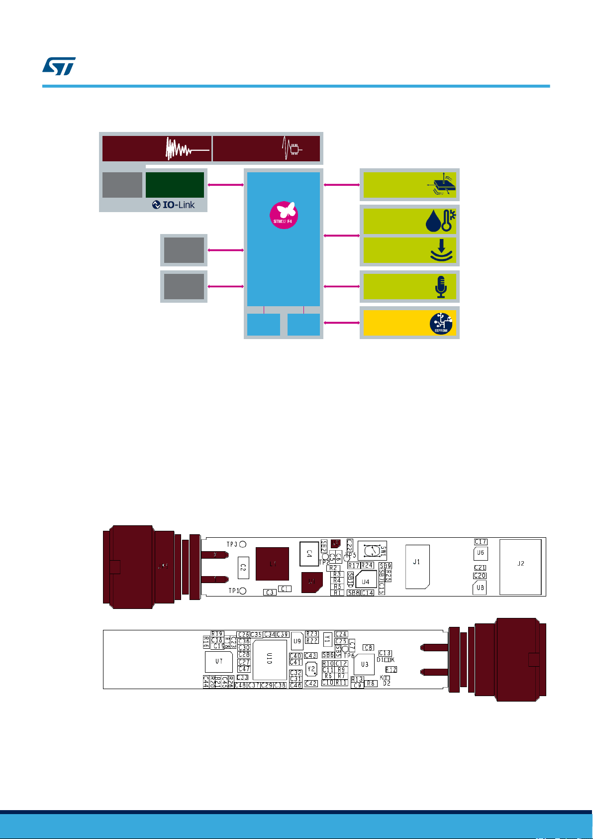
2 STEVAL-IDP005V1 hardware architecture
UM2438
STEVAL-IDP005V1 hardware architecture
Figure 5. STEV
JP1 - IO-Link 4-position M12 A-coded connector
•
•
J1 - SWD connector
• J2 - Auxiliary connector
• SW1 - Reset button
• L1 - Shielded power inductor
• U1 - L6984 step-down switching regulator
• U2 - LDK220 LDO
• U4 - ISM330DLC 3D accelerometer and 3D gyroscope
• U6 - HTS221 humidity and temperature sensor
• U8 - LPS22HB pressure sensor
Figure 6. STEVAL-IDP005V1 bottom side components
• U3 -
• U7 - MP34DT05-A digital microphone
• U9 - M95M01-DF 1-Mbit serial SPI bus EEPROM
• U10 - STM32F469AI ARM® Cortex®-M4 32-bit MCU
• Y1 - 32.768 kHz crystal
• Y2 - 24 MHz crystal
L6362A IO-Link communication transceiver
AL-IDP005V1 top side components
UM2438 - Rev 2
The whole system consists of the following functional subsystems:
1. Power management
2. Microcontroller
3.
MEMS sensors
4. EEPROM
5. Wired connectivity
6. External connectors
The sensors are connected to the microcontroller through separate bus SPI and I2C peripherals.
The connectivity options are:
• UART and I2C on the expansion connectors.
• IO-Link on the M12 male socket.
page 5/67
STM32F469AI
Microcontroller
32 kHz
Crystal
24 MHz
Crystal
ISM330DLC
3D Accelerometer
3D Gyroscope
HTS221
Humidity and
Temperature Sensor
LPS22HB
Pressure Sensor
SPI1
MP34DT05-A
Digital Microphone
I2S2
L6362A
IO-Link Transceiver
USART2
Enhanced
SWD
Connector
UART5
I2C2
ADC3
GPIO
M12 4-pin A-
Coded Male
Socket
Auxiliary
Connector
L6984
step-down switching
regulator
LDK220
LDO
M95M01-DF
1-Mbit SPI bus
EEPROM
SPI4
I2C1
UM2438
Power management
Figure 7. STEV
AL-IDP005V1 functional block diagram
2.1 Power management
The STEVAL-IDP005V1 power management stage can accept an 18 to 32 VDC input through the M12 A-coded 4pin male connector (JP1) and provide 3.3 VDC / 200 mA voltage output to its digital components.
U1 - L6984 step-down switching regulator
•
U2 - LDK220 LDO
•
Figure 8. Power management system
UM2438 - Rev 2
page 6/67
2.1.1 L6984
output voltage adjustability ranges from 0.9 V. The fixed 3.3 V V
“Low Consumption Mode” (LCM) maximizes the ef
“Low Noise Mode” (LNM) makes the switching frequency almost constant over the load current range. The
PGOOD open collector output can implement output voltage sequencing during the power-up phase. The
synchronous rectification, designed for high efficiency at medium - heavy load, and the high switching frequency
capability make the size of the application compact. Pulse-by-pulse current sensing on low-side power element
implements an effective constant current protection.
2.1.2 LDK220
from an input voltage in the range of 2.5 V to 13.2 V, with a typical dropout voltage of 100 mV
stabilizes it on the output. The very low drop voltage, low quiescent current and low noise make it suitable for
industrial applications. The enable logic control function puts the LDK220 in shutdown mode allowing a total
current consumption lower than 1 μA. The device also includes a short-circuit constant current limiting and
thermal protection.
UM2438
Microcontroller
The L6984 is a step-down monolithic switching regulator able to deliver up to 400 mA DC. The
requires no external resistor divider. The
OUT
ficiency at light load with controlled output voltage ripple. The
The LDK220 is a low drop voltage regulator, which provides a maximum output current of 200 mA
. A ceramic capacitor
2.2 Microcontroller
The STEVAL-IDP005V1 embeds an STM32F469AI (U10) ARM®Cortex®-M4 32-bit MCU.
The board has a Serial Wire Debug (SWD) connector (J1) for MCU programming and debugging. This connector
routes UART pins as well.
The board also has a reset button (SW1) to restart the microcontroller.
Figure 9. Microcontroller subsystem
2.2.1 STM32F469AI
The STM32F469AI microcontroller is based on the high-performance ARM® Cortex®-M4 32-bit
RISC core operating at a frequency of up to 180 MHz. The Cortex®-M4 core features a Floating point unit (FPU)
UM2438 - Rev 2
page 7/67
single precision which supports all ARM® single-precision data processing instructions and data types. It also
implements a full set of DSP instructions and a memory protection unit (MPU) which enhances application
security
The device incorporates high-speed embedded memories (Flash memory up to 2 Mbytes, up to 384 Kbytes of
SRAM), up to 4 Kbytes of backup SRAM, and an extensive range of enhanced I/Os and peripherals connected to
two APB buses, two AHB buses and a 32-bit multi-AHB bus matrix.
The device of
two PWM timers for motor control, two general-purpose 32-bit timers, and a true random number generator
(RNG).
The microcontroller features the following standard and advanced communication interfaces:
• Up to three I2Cs.
• Six SPIs, two I2Ss full duplex. To achieve audio class accuracy, the I2S peripherals can be clocked via a
• Four USARTs plus four UARTs.
• One SAI serial audio interface.
The STM32F469AI device operates in the -40 to +105 °C temperature range from a 1.7 to 3.6 V power supply.
.
fers three 12-bit ADCs, two DACs, a low-power R
dedicated internal audio PLL or via an external clock to allow synchronization.
2.2.2 Enhanced SWD connector
The STEVAL-IDP005V1 has a 1.27 mm pitch, 10-contact, 2-row board-to-board connector. The connector can be
used for the following purposes:
•
To program the microcontroller via a dedicated adapter (STEVAL-UKI001V1) connected to the programming
tool (e.g. ST-LINK/V2-1).
• As an expansion connector that routes the UART pins, to allow the STEVAL-IDP005V1 to connect with a PC
COM port. A further IO for USER_LED is also routed.
UM2438
Sensors
TC, twelve general-purpose 16-bit timers including
2.3 Sensors
The STEVAL-IDP005V1 embeds several sensors to detect vibration, environmental parameters and sound
parameters. The sensor data is analysed with algorithms running on the STM32F469AI microcontroller with FPU.
The following sensors are mounted on the board:
•
U4 - ISM330DLC 3D accelerometer and 3D gyroscope
U6 - HTS221 humidity and temperature sensor
•
• U8 - LPS22HB pressure sensor
• U7 - MP34DT05-A digital microphone
Figure 10. Enhanced SWD connector
UM2438 - Rev 2
page 8/67
2.3.1 ISM330DLC
UM2438
Sensors
Figure 11. Sensor array subsystem
The ISM330DLC is a system-in-package featuring a high performance 3D digital accelerometer and
3D digital gyroscope tailored for Industry 4.0 applications.
ST’s family of MEMS sensor modules leverages the robust and mature manufacturing processes already used for
the production of micro machined accelerometers and gyroscopes.
The various sensing elements are manufactured using specialized micromachining processes,
while the IC interfaces are developed using CMOS technology that allows the design of a dedicated circuit which
is trimmed to better match the characteristics of the sensing element.
In the ISM330DLC, the sensing element of the accelerometer and of the gyroscope are implemented on the same
silicon die, thus guaranteeing superior stability and robustness.
The ISM330DLC has a full-scale acceleration range of ±2/±4/±8/±16 g and an angular rate range of
±125/±250/±500/±1000/±2000 dps.
Delivering high accuracy and stability with ultra-low power consumption (0.75 mA in high-performance, combo
mode) enables, also in the industrial domain, long-lasting battery operated applications.
The ISM330DLC includes a dedicated configurable signal processing path with low latency
dedicated filtering specifically intended for control loop stability. Data from this dedicated signal path can be made
available through an auxiliary SPI interface, configurable for both the gyroscope and accelerometer. Highperformance, high-quality, small size and low power consumption together with high robustness to mechanical
shock makes the ISM330DLC the preferred choice of system designers for the creation and manufacturing of
versatile and reliable products.
The ISM330DLC is available in a plastic, land grid array (LGA) package.
The STSW-BFA001V1 firmware package includes applications and demonstrations firmware supporting
accelerometer part.
, low noise and
2.3.2 HTS221
element and a mixed signal ASIC to provide the measurement information through digital serial interfaces.
UM2438 - Rev 2
The HTS221 is an ultra-compact sensor for relative humidity and temperature. It includes a sensing
page 9/67
The sensing element consists of a polymer dielectric planar capacitor structure capable of detecting relative
humidity variations and is manufactured using a dedicated ST process.
The HTS221
temperature range from -40 °C to +120 °C.
2.3.3 LPS22HB
digital output barometer. The device comprises a sensing element and an IC interface which communicates
through I2C or SPI from the sensing element to the application.
The sensing element, which detects absolute pressure, consists of a suspended membrane manufactured using a
dedicated process developed by ST.
The
LPS22HB is available in a full-mold, holed LGA package (HLGA). It is guaranteed to operate over a
temperature range extending from -40 °C to +85 °C. The package is holed to allow external pressure to reach the
sensing element.
2.3.4 MP34DT05-A
UM2438
Memory
is available in a small top-holed cap land grid array (HLGA) package guaranteed to operate over a
The LPS22HB is an ultra-compact piezoresistive absolute pressure sensor which functions as a
with a capacitive sensing element and an IC interface.
The sensing element, capable of detecting acoustic waves, is manufactured using a specialized silicon
micromachining process dedicated to producing audio sensors.
The IC interface is manufactured using a CMOS process that allows designing a dedicated circuit able to provide
a digital signal externally in PDM format.
The MP34DT05-A is a low-distortion digital microphone with a 64 dB signal-to-noise ratio and -26 dBFS ±3 dB
sensitivity
The MP34DT05-A is available in a top-port, SMD-compliant, EMI-shielded package and is guaranteed to operate
over an extended temperature range from -40 °C to +85 °C.
2.4 Memory
The STEVAL-IDP005V1 has non-volatile memory which can store up to 1-Mbits of data.
•
U9 - M95M01-DF 1-Mbit serial SPI bus EEPROM
The MP34DT05-A is an ultra-compact, low-power, omnidirectional, digital MEMS microphone built
.
Figure 12.
EEPROM subsystem
UM2438 - Rev 2
page 10/67
2.4.1 M95M01-DF
The M95M01 electrically erasable programmable memory (EEPROM) id organized as 131072 x 8
bits, accessed through the SPI bus.
The M95M01-DF can operate with a supply range from 1.7 V up to 5.5 V. This device is guaranteed for the -40
°C/+85 °C temperature range.
The M95M01-DF of
application parameters that can subsequently be permanently locked in Read-only mode.
fers an additional Identification Page (256 bytes), which can be used to store sensitive
2.5 IO-Link communication
The STEVAL-IDP005V1 board has IO-Link connectivity available on the M12 A-coded connector.
IO-Link is an industrial standard for hardware connectivity
• the number of wires needed for the bus installation
•
the colors to distinguish supply voltage from the IO-Link bus line
• connector pinouts.
The standard also establishes two different data communication methods:
1. Pure serial data communication (SDCI) with a detailed protocol structure to manage sensor parameters and
sensor data.
2. A simple level transition high to low and vice versa to signal the sensor status only.
The use of an IO-Link system offers several advantages, like:
• Automatic detection and parameterization of the IO-Link device: the operating parameters of devices are
stored in the master during setup. Once connected, the master recognizes the device and enables automatic
startup. If a device like a sensor fails, it can be replaced and parameterization data stored in the master is
automatically downloaded to the replacement device.
• Device monitoring and diagnostics: IO-Link allows equipment components and systems to be monitored and
proactively managed. Diagnostics provided by IO-Link devices lets the control system track data and trends,
facilitating preventive and predictive maintenance and improving machine uptime.
• Changes on the fly: parameters can be quickly adjusted for installed devices while the machine is running,
reducing time consumption.
• Reduced component costs: by exploiting the configuration capabilities of IO-Link, a device can be configured
to have different output functions.
UM2438
IO-Link communication
. The standard specifies:
Figure 13. IO-Link subsystem
UM2438 - Rev 2
page 11/67
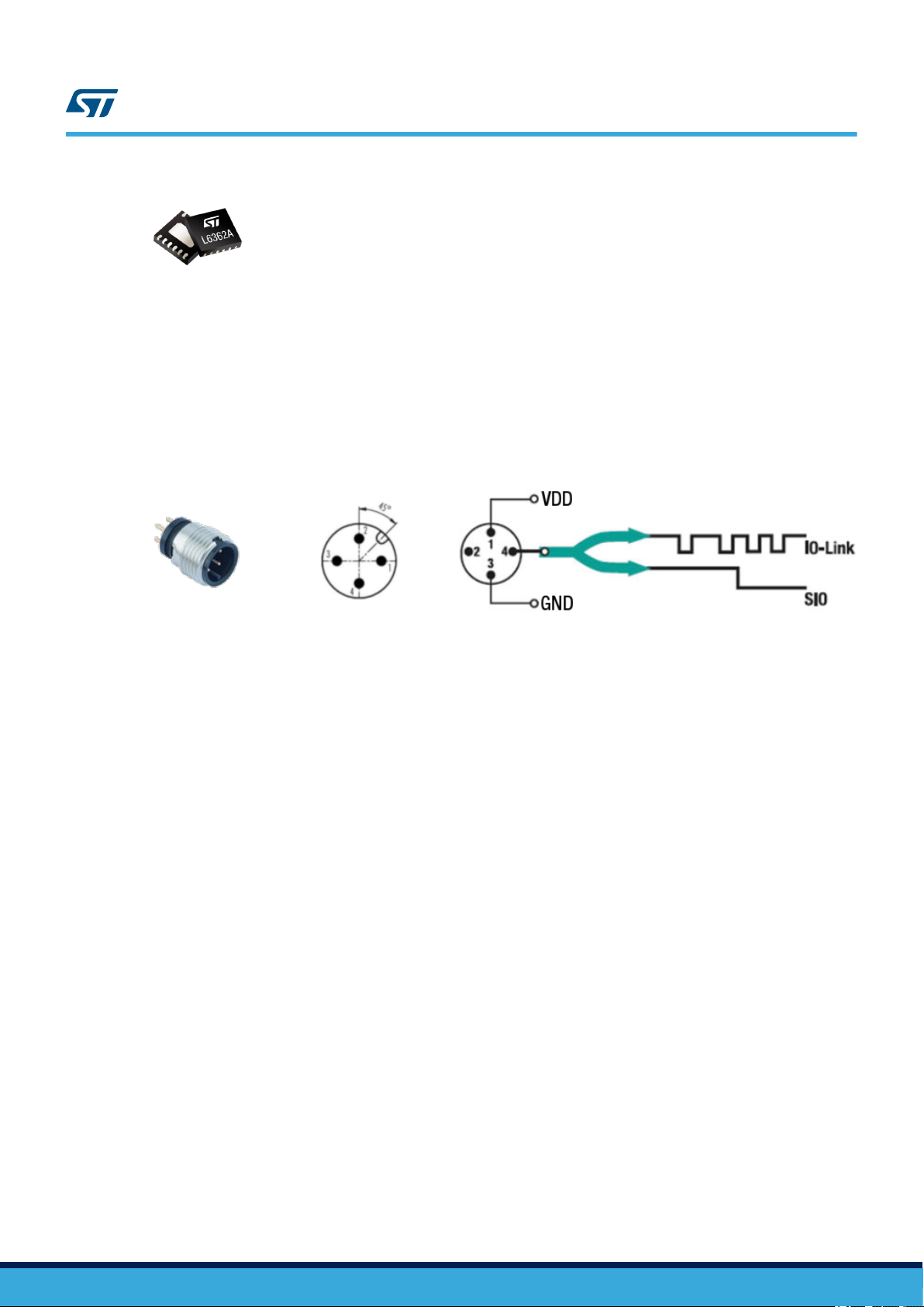
2.5.1 L6362A
The L6362A is an IO-Link transceiver device compliant with PHY2 (3-wire connection) supporting
COM1 (4.8 kbaud), COM2 (38.4 kbaud) and COM3 (230.4 kbaud) modes. The output stage can be configured as
high-side, low-side or push-pull by hardware connection, and it can drive resistive, capacitive and inductive loads.
The IC can interface a sensor node to a master unit using both the Serial Data Communication Interface (SDCI)
based on IO-Link protocol and the Standard I/O mode (SIO). Communication is managed using the 24 V industrial
bus voltage. The L6362A is protected against reverse polarity across VCC, GND, OUTH, OUTL and I/Q pins. The
IC is also protected against output short-circuits, overvoltage and fast transient conditions (±1 kV, 500 Ω and 18
μF coupling).
2.5.2 IO-Link connector
The IO-Link connector is M12 A-coded 4-pin.
UM2438
Auxiliary connections
Figure 14. IO-Link connector and signals
2.6 Auxiliary connections
The STEVAL-IDP005V1 comes with a 6-pin auxiliary connector for:
• VDD and GND
• SMBus (I2C)
•
One ADC channel
The above pins can still be used as GPIOs.
The mounted auxiliary connector is a JST SM06B-NSHSS-TB. This mates with a JST NSHR-06V-S, female
connector housing, that be assembled with six JST SSHL-003T-P0.2, female crimp terminal contact. These
components are not part of the kit.
UM2438 - Rev 2
page 12/67
3 STEVAL-UKI001V1
VDD_TARGET
SWCLK
3
USR_BTN
VDD_TARGET
SWCLK
CN13
4
SWO
SWO_RS232_RX
SWDIO
4-pin Male Header
5
100 mils 20-pin Header
CN2_1
8
miniswitch-KMR211GLFS
USR_BTN
NRST
590
Not Mounted
JP1
2
3-pin Male Header
6
SWO_RS232_RX
4
2
GND
C1
1-pin Male Header
6
SWCLK
CN2_2
Fit on STM32 Nucleo board
GND
RST
SWO
3
1
SW1
2
18
RS232_TX
5
7
C2
2-pin Female Header
ST_LINK_RX
GND
SWO
1
USR_LED
1
14
miniswitch-KMR211GLFS
4-pin Female Header
20
mounted on TOP
mounted on TOP
mounted on BOTTOM
SW2
10 to 20 pin Serial Wire Debug (SWD) adapter
J2
2
3
1
17
1
8
GND
VDD_TARGET
CN14
11
CN2_4
10
100nF
CN2
2
CN2_3
SWDIO
1
J3
CN3
LED (Yellow)
6-pin Female Header
NRST
3
CN2_3
9
USR_BTN
1
ST_LINK_3V3
ST_LINK_RX
2-pin Male Header
NRST
4
6
CN4
2
2-pin Female Header
2-pin Female Header
ST_LINK_TX
3
9
CN15
USR_LED
NRST
CN2_2
2
16
SWDIO
ST_LINK_3V3
CN2_1
D1
1
3
100nF
10
2-pin Male Header
R1
CN2_4
1
CN12
12
13
ST_LINK_TX
4
5
1
15
JP2
GND
2
50 mils 10-pin Header
2
closed 2-3
J1
Not Mounted
closed
VDD_TARGET
GND
4
RS232_TX
7
19
This tool is an adapter for Serial Wire Debug (SWD) from 10-pin 50-mil socket to 20-pin 100-mil socket (mounted
on ST
-LINK/V2) or to 6-pin 100-mil (mounted on ST
The ST
-LINK/V2-1 of the STM32 Nucleo-64 board offers more features. However, you need to ensure that the
target application routes the UART RX, UART TX, user button and user LED tracks correctly on the SWD.
You can use ST-LINK/V2-1 through the STEVAL-UKI001V1 board to program and debug the target application.
You can also use the ST-LINK/V2-1 as a UART interface adapter via the STM32 Virtual COM Port Driver. This
allows you to keep using the USB cable that connects the kit to your PC. To use this configuration, ensure that
pins 2 and 3 of CN14 and pins 1 and 2 of CN15 are shorted. Refer to the schematic below.
UM2438
STEVAL-UKI001V1
-LINK/V2-1 on the STM32 Nucleo-64 board).
Figure 15. STEVAL-UKI001V1 schematic
UM2438 - Rev 2
page 13/67
UM2438
STEVAL-UKI001V1
Figure 16. STEV
Figure 17. STEV
AL-UKI001V1 top view
AL-UKI001V1 bottom view
UM2438 - Rev 2
page 14/67
How to supply power to the STEVAL-IDP005V1 board
4 How to supply power to the STEVAL-IDP005V1 board
The STEVAL-BFA001V1B kit includes the necessary cable and connectors to power the STEVAL-IDP005V1
board.
Figure 18. 4-wire cable with free ends and an M12 A-coded 4-pin female connector
UM2438
Figure 19. 4-pole cable mount connector plug with male contacts
RELATED LINKS
1.3 How to run the demo supplied with the firmware on page 4
4.1 Supply power directly from a DC power supply
You can power the board directly from a DC power supply using only the cable provided in the kit.
Step 1. Connect the cable to an 18 – 32 VDC power supply:
Pin 1 (brown wire) to positive
–
– Pin 3 (blue wire) to negative
Figure 20. STEV
AL-IDP005V1 power supply connection (without IO-Link master board)
4.2 Supply power through an IO-Link master board
You can supply power via an IO-Link master board using the cable and connectors provided in the kit.
Step 1. Attach the 4-pole cable mount connector plug with male contacts to the cable.
Step 2. Connect the female end to the STEV
master board.
UM2438 - Rev 2
AL-IDP005V1 board and the male end to the STEVAL-IDP004V1
page 15/67
UM2438
Supply power through an IO-Link master board
Step 3. Power the STEV
connector CON1.
Figure 21.
AL-IDP004V1
IO-Link master board with an 18 to 32 VDC supply through screw
STEVAL-IDP005V1 power supply connection (through IO-Link master board)
UM2438 - Rev 2
page 16/67
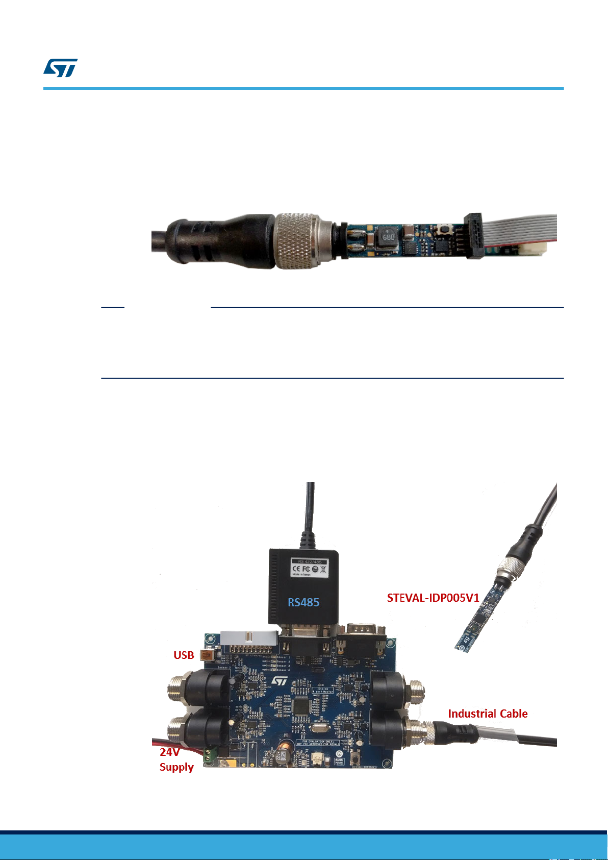
5 STEVAL-IDP005V1 board connections
The STEVAL-IDP005V1 needs to be linked with a PC to manage the data coming from the board. The connection
can either be through a serial communication adapter (ST
STEV
AL-IDP004V1).
(
5.1 Connection through an ST-LINK/V2-1
The ST-LINK/V2-1 in-circuit debugger/programmer on the STM32 Nucleo-64 board lets you update the STEVALIDP005V1 firmware. It also allows UART communication with a PC.
To enable UART communication
Step 1. Install the STM32 Virtual COM Port Driver (STSW-STM32102) on your PC.
Step 2. Run a terminal emulator like PuTTY, Tera Term, etc.
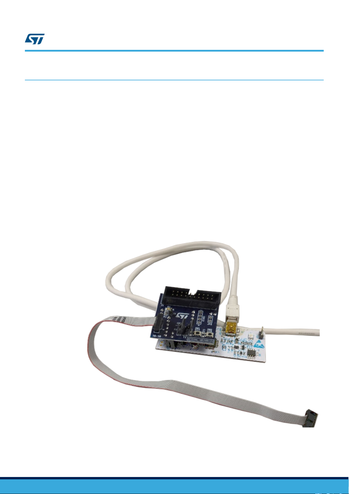
To set up a connection for firmware update.
Step 3. Plug the STEVAL-UKI001V1 on ST-LINK/V2-1 in a manner that the connectors with the same
identification are overlapped.
Step 4. Connect the ST-LINK/V2-1 to the PC through the USB Type-A Male to Type-B mini cable.
Step 5. Respecting the polarity, connect an end of the 10-pin flat IDC wire cable to J2 of the STEVAL-
UKI001V1.
-LINK/V2-1) or an IO-Link master multi-port board
UM2438
STEVAL-IDP005V1 board connections
Figure 22. ST-LINK/V2-1 connection
UM2438 - Rev 2
Step 6. On the STEVAL-UKI001V1, short the CN14 pin 2-3 and the CN15.
Step 7. Use the 4-wire cable with free ends and an M12 A-coded 4-pin female connector (e.g. Telemecanique
Sensors XZCP1141L2).
page 17/67
UM2438
Connection through an STEVAL-IDP004V1
Step 8. Connect the M12 A-coded 4-pin female connector of the cable to JP1 (IO-Link connector) of the
STEV
AL-IDP005V1.
Step 9. Connect wire 1 (VIN) and wire 3 (GND) of the cable to a power supply able to provide 18 to 32 VDC.
Step 10. Respecting the polarity
the STEV
AL-IDP005V1.
The STEVAL-IDP005V1 is ready to be programmed with new firmware.
RELATED LINKS
1.3 How to run the demo supplied with the firmware on page 4
6.2.4.3 Demonstrations folders on page
8 How to run projects via IO-Link on page 42
7.1 Outputs for the acoustic analysis project on page 29
, connect the free end of the 10-pin flat IDC wire cable to J1 (SWD connector) of
Figure 23. IO-Link and SWD connection
25
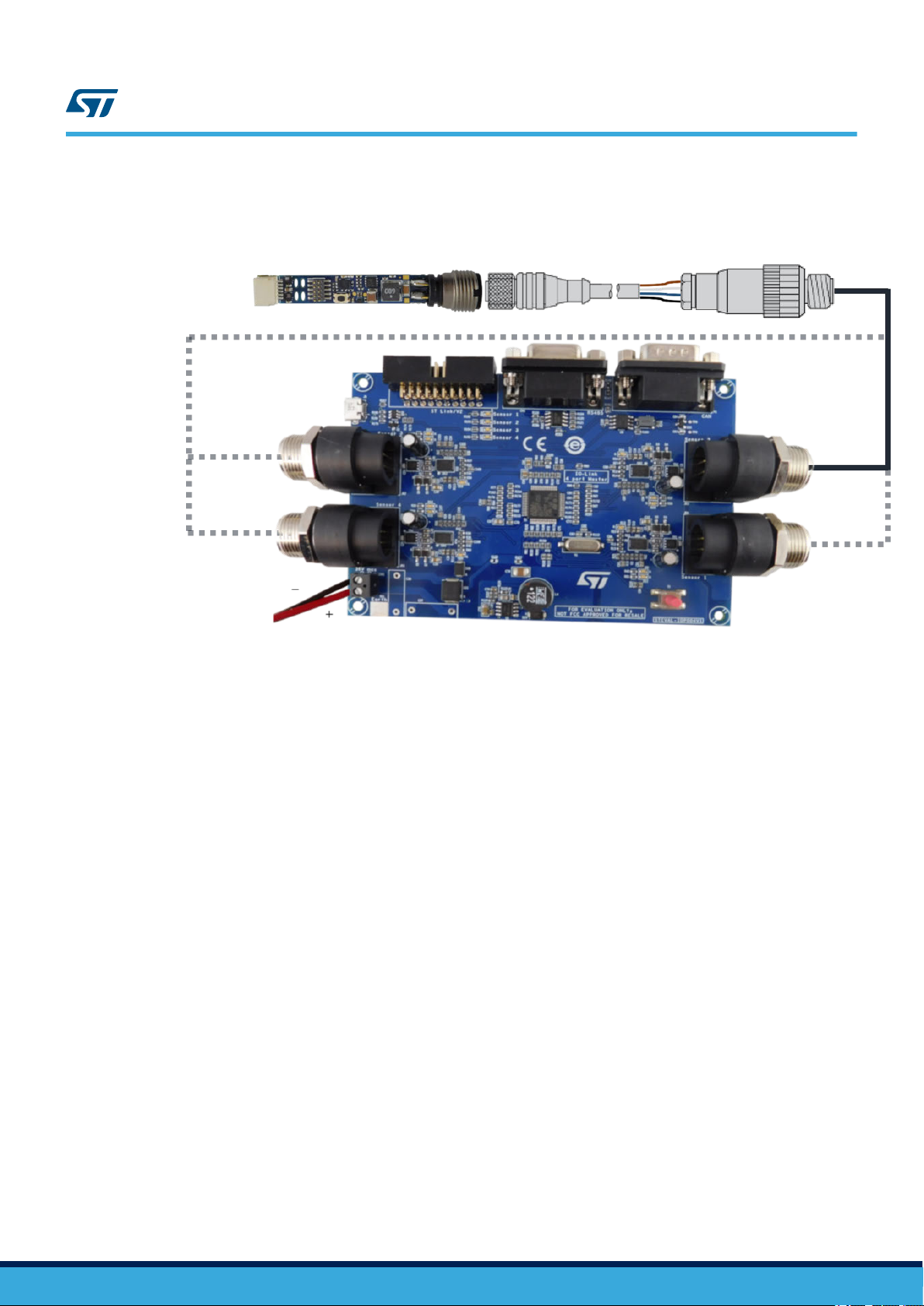
5.2 Connection through an STEVAL-IDP004V1
The physical IO-Link connection between STEVAL-IDP005V1 and the PC is made using the STEVAL-IDP004V1
multiport master board with an L6360 master IC for each IO-Link port.
Step 1. Ensure that none of the boards are connected to a power supply.
Figure 24. STEV
AL-IDP004V1 vs STEVAL-IDP005V1 connections
UM2438 - Rev 2
page 18/67

UM2438
Connection through an STEVAL-IDP004V1
Step 2. Assemble the T
elemecanique Sensors XZCP1
141L2 (4-wire cable) with the T
elemecanique Sensors
XZCC12MDM40B (4-pole connector).
You can also use a preassembled 4-wire cable (not provided in the package) with M12 A-coded 4-pin
connectors, male on one end and female on the other.
Step 3. Plug the female M12 connector of the cable to the STEVAL-IDP005V1.
Step 4. Plug the male M12 connector of the cable to a free port of the four ones that are in the STEVAL-
IDP004V1.
Step 5. Connect the RS485 dongle (not present in the package) and install the related driver to create the
physical connection between PC and master board.
For correct communication, use the reference pinout on the DB9 connector shown below.
Table 1. RS485 Connector pinout
PIN Number PIN Description
1 , 4 Inverting receiver input and inverting driver output
2 , 8 Non inverting receiver input and non-inverting driver output
6 , 7 , 9 Not connected
3 , 5 Ground
Step 6. Connect an 18 to 32 V (typ. 24 V) supply voltage through screw connector CON1 on the board to run
the system.
RELATED LINKS
6.2.4.3 Demonstrations folders on page 25
8 How to run projects via IO-Link on page 42
Graphical Interface overview on page 43
9
UM2438 - Rev 2
page 19/67

6 Firmware overview
UM2438
Firmware overview
The STSW
applications using inertial, environmental and microphone sensors. The firmware includes sample condition
monitoring and predictive maintenance applications based on 3D digital accelerometer, environmental and
acoustic MEMS sensors.
The software uses the following lower layers:
•
•
• Medium level board support package (BSP) layer to provide on-board sensor control and data reception at
The middleware libraries built on top of the lower layers provide the following features:
• Middleware, including algorithms for advanced time and frequency domain signal processing for vibration
• Middleware with microphone algorithms:
• Sample application to monitor environmental, acoustic and vibration data and read algorithm outputs through
• Sample application with programmable warning and alarm thresholds in the time domain and across spectral
• Application example firmware to communicate with STEVAL-IDP004V1 (IO-Link master multi-port evaluation
-BFA001V1 software is an expansion of the STM32Cube platform with functions to help you develop
Low level STM32Cube HAL layer to provide all the MCU communication peripherals APIs compatible with
STM32Cube framework.
Low level drivers to facilitate sensor configuration and data reception with dedicated APIs that are
compatible with STM32Cube framework.
the application level.
analysis:
– For the frequency domain:
◦ Programmable FFT size (256, 512, 1024, 2048)
◦ Programmable FFT input data overlapping
◦ Programmable FFT input data windowing (Flat Top, Hanning, Hamming)
◦ Programmable FFT output averaging
◦ Programmable FFT subrange analysis
– For the time domain:
◦ HP filtering to reduce accelerometer offset
◦ Accelerometer max peak evaluation
◦ Accelerometer integration to evaluate Speed
◦ Moving RMS speed evaluation
– PDM to PCM
– Sound pressure
– Audio FFT
a terminal emulator.
bands.
board) and dedicated PC GUI.
6.1 Firmware architecture
The firmware is based on the STM32Cube™ framework for applications running on the STM32 microcontroller.
The package provides a board support package (BSP) for the MEMS and Microphone sensors and other devices
used for IO-Link communication. The package also contains middleware for signal and audio processing.
UM2438 - Rev 2
page 20/67
Demonstrations
Applications
Condition
Monitoring
Predictive
Maintenance
Acoustic
Analysis
Vibration
Analysis
Environmental
Monitoring
Vibration Signal Processing
Audio Lib
STM32Cube Hardware
Abstraction Layer
Board Support
Package
Middleware
Hardware
Abstraction
Hardware
STM32F469AI, ISM330DLC, LPS22HB, HTS221, MP34DT05-A
STEVAL-IDP005V1
User interfaces
and utilities
STEVAL-IDP005V1 GUI
UART / Windows terminal
(vibration, acoustic and
environmental data monitoring)
UM2438
Firmware architecture
Figure 25. STSW
A001V1 firmware architecture
-BF
The following firmware layers access and use the hardware components:
• STM32Cube HAL layer: generic Application Programming Interfaces (APIs) which interact with higher level
applications, libraries and stacks. The APIs are based on the common STM32Cube framework so other
layers like middleware can function without requiring specific hardware information for a given
microcontroller unit (MCU).
• Board support package (BSP) layer: provides firmware support for the STM32 (excluding MCU) peripherals.
These APIs provide a programming interface for certain board-specific components like LEDs, user buttons,
etc. The APIs can also fetch board serial and version information, as well as support initializing, configuring
and reading data from sensors. The BSP provides the drivers for the STEV
to connect to the microcontroller peripherals.
This firmware package expands the functionality of the STM32Cube platform with the following features for
specific industrial applications:
• Low and middle level drivers to connect all the on-board MEMS sensors:
– Pressure and temperature sensor (LPS22HB)
– Humidity and temperature sensor (HTS221)
– Accelerometer/Gyroscope motion sensors (ISM330DLC)
– Digital Microphone audio sensor (MP34DT05-A)
• Complete BSP functions to allow applications to access sensors. The data acquisition from different sensors
is provided via SPI and I2C.
• Six different sample firmware projects divided into two main groups:
– Applications: examples that use motion, environmental and acoustic measurements, including
• Command line interface (CLI) using a debug console on an external terminal via UART communication with
middleware algorithms focused on vibration and acoustic analysis and environmental monitoring.
– Demonstrations: projects designed to demonstrate condition monitoring and predictive maintenance
with the STEVAL-IDP005V1. The projects include IO-Link connectivity with the master board (STEVAL-
IDP004V1).
a PC.
AL-IDP005V1 board peripherals
UM2438 - Rev 2
page 21/67

6.2 Firmware folder structure
The STSW-BFA001V1 package is developed using the standard STM32Cube™ framework structure shown
below.
UM2438
Firmware folder structure
Figure 26. STSW
6.2.1 Documentation
The documentation folder contains a compiled HTML file generated from doxygen comments in the source code.
The folder also has documentation regarding the firmware framework, drivers for the on-board components and
APIs to manage the different functions.
Note: For more information, open the STEV
6.2.2 Drivers
All firmware packages compliant with the STM32Cube framework contain the following main groups:
•
BSP: board-specific drivers for the HW components.
• CMSIS: vendor-independent hardware abstraction layer for the ARM Cortex-M series, including DSP
libraries used for the projects.
STM32F4xx_HAL_Drivers: microcontroller HAL libraries.
•
The board support package files are grouped into two main folders with the low level hardware device drivers and
the board-specific medium level drivers:
• Components: includes a set of platform-independent device drivers for LPS22HB, HTS221, ISM330DLC,
M95M01-DF, as well as common files.
• STEVAL-IDP005V1: includes a set of medium level drivers for each hardware subsystem. You can use the
drivers in your application to control and configure the functionality of different measurement datatypes.
These APIs abstract the on-board hardware and connectivity devices contained in the steval_idp005v1 module for
use by applications.
-BFA001V1 firmware folder structure
AL-IDP005V1_FW.chm help file in the documentation folder.
6.2.3 Middleware
The Middlewares folder contains two specific libraries that give higher level applications access to APIs for
acoustic and motion signal processing analysis.
6.2.4 Projects
The Projects directory contains several user projects under Applications and Demonstrations subfolders.
UM2438 - Rev 2
page 22/67

Figure 27. Projects folders
UM2438
Firmware folder structure
All the projects are available for the following integrated development environments (IDE):
• IAR Embedded Workbench® for ARM® (EW
• Microcontroller Development Kit for ARM® (MDK-ARM) by Keil
• System Workbench for STM32 (SW4STM32) by AC6 (free IDE)
6.2.4.1 Standard files for all projects
The standard STM32Cube application files have the same configuration as any standard example using the
STM32 HAL libraries, plus the peripherals used for demonstration purposes in the following files:
• main.c: APIs for system clock configuration and all the standard include files for the other APIs defined in
HAL libraries, BSP and Middleware.
• stm32f4xx_hal_msp.c: APIs for application-level peripheral initialization.
stm32f4xx_hal_it.c: APIs for all interrupt handlers.
•
6.2.4.2 Applications folder
The Applications folder includes separate projects and reference firmware to monitor (through serial
communication via the
STEVAL-UKI001V1
1. Vibration data: with vibration analysis based on accelerometer data for diagnostic purposes.
2. Audio data: retrieves sound data such as sound pressure level and sound power spectrum.
3. Environmental data: retrieves environmental data such as humidity, temperature and pressure.
ARM) by IAR systems
®
®
) the following types of data from the STEVAL-IDP005V1:
UM2438 - Rev 2
page 23/67

Figure 28. Applications folders
UM2438
Firmware folder structure
6.2.4.2.1 Application-specific files for projects in the Applications folder
The application-specific APIs for vibration analysis are found in the following files:
• main.c:
– APIs for sending application information to a terminal screen (via Service UART)
– APIs for sensor initialization (accelerometer)
– APIs for sensor measurement (accelerometer)
– APIs for accelerometer parameters that can be configured by the user, and accelerometer INT
management
– APIs for time domain and frequency domain analyses
• data_communication_srv.c: APIs for the CLI configuration command and to monitor the processing outputs
requested by the user.
• audio_application.c: to interface with middleware functions.
UM2438 - Rev 2
page 24/67

6.2.4.3 Demonstrations folders
The Demonstrations folder includes three projects for the STEVAL-IDP005V1:
1. Predictive Maintenance with serial communication via STEVAL-UKI001V1.
Condition Monitoring:
2.
a. with serial communication via IO-Link
b. with serial communication via UART through the STEVAL-UKI001V1
UM2438
Firmware folder structure
Figure 29. User files for vibration analysis
UM2438 - Rev 2
page 25/67

Figure 30. Demonstrations folders
UM2438
Firmware folder structure
UM2438 - Rev 2
The project for Predictive Maintenance analyzes vibration data against threshold parameters for the same
measurement datatype evaluated. The project includes a algorithm to determine status information with respect to
time and frequency domain parameters.
There are two Condition Monitoring projects designed to retrieve and analyze sensor data to evaluate equipment
status.
The two projects dif
fer in how the data is transmitted.
page 26/67

1. The Conditon_Monitoring_SRV project uses standard communication with a PC via the STEVAL-UKI001V1
mounted on STLINK/V2-1.
2.
The Conditon_Monitoring_IOL project uses the IO-Link communication PHY, interfacing the STEV
IDP005V1 with the STEV
AL-IDP004V1 master board and sending the received data via a RS485-USB
adapter to a PC. This methods lets you monitor the system with the STSW-IO-LINK GUI.
RELATED LINKS
5.1 Connection through an ST-LINK/V2-1 on page 17
5.2 Connection through an STEVAL-IDP004V1 on page 18
9 Graphical Interface overview
6.2.4.3.1 Application-specific files for the Conditon_Monitoring_SRV project
The application-specific APIs for the Conditon_Monitoring_SRV project are found in the following files:
• main.c
– APIs for sending the application information to the terminal screen (via Service UART)
–
APIs for sensor initialization (accelerometer, humidity, pressure and temperature)
– APIs for sensor measurement (accelerometer, humidity, pressure and temperature)
– APIs for external memory Init (EEPROM)
– APIs for accelerometer parameters that can be configured by the user, and accelerometer INT
management
– APIs for time domain and frequency domain analyses
• data_communication_srv.c: APIs to run the CLI configuration command and to monitor requested processing
outputs.
• MotionSP_Manager.c: to interface with middleware functionality.
on page 43
UM2438
Firmware folder structure
AL-
Figure 31. User files for Conditon_Monitoring_SRV project
6.2.4.3.2 Application-specific files for the Conditon_Monitoring_IOL project
The application-specific APIs for the Conditon_Monitoring_IOL project are found in the following files:
•
main.c
– APIs for sending the application information to the terminal screen (via IO-Link PHY device)
APIs for sensor initialization (accelerometer, humidity, pressure and temperature)
–
– APIs for sensor measurement (accelerometer, humidity, pressure and temperature)
UM2438 - Rev 2
page 27/67

Firmware folder structure
– APIs for time domain and frequency domain analyses
•
data_communication_iol.c: APIs designed to receive many customized commands from a board with IO-Link
, and to send sensor and processing datatypes. Master-slave node communication is managed
Master
through the IO-Link channel.
•
MotionSP_Manager.c: to interface with middleware functionality.
UM2438
UM2438 - Rev 2
page 28/67

7 How to run projects via Service UART
Perform the following steps for any of the projects available for Service UART:
Step 1. Connect the STEV
Nucleo-64 and download the dedicated firmware.
Step 2. Run a terminal emulator like PuTTY on your PC
Be sure to use the correct COM port and UAR
Step 3. Press the reset button to restart the application.
AL-IDP005V1 to an ST
7.1 Outputs for the acoustic analysis project
The terminal emulator for acoustic analysis shows the following information:
-LINK/V2-1 in-circuit debugger/programmer on the STM32
T parameters: 921600/8-N-1
UM2438
How to run projects via Service UART
Figure 32. T
The log file from the terminal emulator will store the following information:
• the measured sound pressure and its acquisition time
• the measured average power spectrum with its peak and its acquisition time.
erminal emulator screenshot for acoustic analysis firmware
UM2438 - Rev 2
page 29/67

Outputs for the acoustic analysis project
Figure 33. Acoustic analysis terminal emulator log file
UM2438
UM2438 - Rev 2
RELATED LINKS
1.3 How to run the demo supplied with the firmware on page 4
5.1 Connection through an ST-LINK/V2-1 on page
17
page 30/67

Outputs for the environmental monitoring project
7.2 Outputs for the environmental monitoring project
The terminal emulator will show the following information:
Figure 34. Terminal emulator screenshot while running environmental monitoring firmware
UM2438
UM2438 - Rev 2
The log file from the terminal emulator will store the following information:
• the measured sound pressure and its acquisition time
page 31/67

Outputs for the environmental monitoring project
Figure 35. Environmental monitoring terminal emulator log file
UM2438
UM2438 - Rev 2
page 32/67

7.3 Outputs for the vibration analysis project
The terminal emulator will show the following information:
Figure 36. Terminal emulator screenshot while running vibration analysis firmware
UM2438
Outputs for the vibration analysis project
UM2438 - Rev 2
The bottom part of the screen lists the stored parameters for the analysis and prompts you to change any of these
parameters. The configurable parameters are:
odr
Use the same values available for the specific accelerometer (ISM330DLC) to ensure high performance: 13 (for
12.5), 26, 52, 104, 208, 416, 833, 1660, 3330, 6660. See the ISM330DLC datasheet for further details.
fs
The configurable values are: 2, 4 (default), 8, 16. See ISM330DLC datasheet for further details.
hpf
Cutof
f frequency for internal hardware High Pass Filter (HPF) as per the following table:
Table 2. HPF configuration
HPF configuration Cutoff frequency selected
0 ODR/4
1 ODR/100
2 ODR/9
page 33/67

UM2438
Outputs for the vibration analysis project
HPF configuration Cutoff frequency selected
3 (Default) ODR/400
4 NO_HPF
size
FFT input array accelerometer size: 256, 512, 1024, or 2048 (default)
ovl
Overlapping between the following FFT input array in percentage; use a value between 5% and 95% (75% default)
tacq
T
otal acquisition time (in ms) to evaluate all the parameters for the time domain and frequency domain analysis in
the same time.
tau
Time parameter to include for the moving root mean square (RMS) evaluation (for speed and/or acceleration);
choose a value from: 25, 50, 100, 150, 250, 500 (default), 1000, 1500 and 2000.
subrng
Subrange FFT numbers to evaluate the frequency domain analysis results in each subrange frequency sector;
choose a value from 8, 16 (default), 32, or 64 (this parameter is used by the condition monitoring project.
wind
Filter windowing type; choose from:
0 - Hanning (default)
•
• 1 - Hamming
• 2 - Flat Top
tdtype
Time domain datatype format:
• 0 - Speed RMS only
• 1 - Acceleration RMS only
• 2 - Speed RMS and Acceleration RMS
Once you have inserted the new parameters, the Command Line Interface prompts you to type [y] and press
[Enter] to confirm the new values.
UM2438 - Rev 2
page 34/67

Outputs for the vibration analysis project
Figure 37. Default parameter list and starting point
UM2438
UM2438 - Rev 2
After the parameter setting phase, all the configurations are started and checked, and some information is also
returned about the MotionSP algorithm that is about to be launched.
page 35/67

Figure 38. MotionSP Initialization
UM2438
Outputs for the vibration analysis project
The terminal emulator will show the following information:
• Time domain analysis X-Y
-Z arrays according to the tdtype and tacq (timing window) parameters,
transmitting the data every 5 ms. The figure below lists the following information:
– the real ODR evaluated by the algorithm in order to have a more accurate value for the FFT arrays;
– the time domain datalog with the timestamp in the first column, and the X-Y-Z value chosen, in order to
plot the RMS speed trend mm/s.
UM2438 - Rev 2
page 36/67

UM2438
Outputs for the vibration analysis project
Figure 39. T
ime domain data
• Frequency Domain X-Y-Z arrays according to the parameter settings for the configured timing window (tacq)
as well as the bin frequency information. The output shows the acceleration power spectrum in m/s².
Figure 40. Frequency domain data
UM2438 - Rev 2
• Frequency Domain final results, including the average number of FFTs used during processing processing.
Figure 41. FFT results
• The maximum X-Y-Z acceleration peak.
page 37/67

UM2438
Outputs for the vibration analysis project
Figure 42. Maximum X-Y
-Z acceleration peak
• The final step lets you change some parameters again and run a new analysis.
Figure 43. Summary window
UM2438 - Rev 2
page 38/67

7.4 Condition Monitoring via Service UART
The terminal emulator will show the following information:
Figure 44. Condition Monitoring header log
UM2438
Condition Monitoring via Service UART
UM2438 - Rev 2
This project includes the components developed for vibration analysis, environmental measurement and a
specific frequency domain analysis that uses subranges to show the harmonics contributing across the power
spectrum bandwidth.
• The environmental sensor measurements are listed below:
page 39/67

Figure 45. Environmental data
7.5 Predictive Maintenance via Service UART
Predictive Maintenance is based on continuous comparison of vibration data with threshold values, which may be
provided by the machinery manufacturer. The objective is to monitor potentially damaging conditions that cannot
be identified in conventional scheduled maintenance.
The STEVAL-IDP005V1 firmware lets you modify time domain and frequency domain conditions:
Time domain thresholds with three different warning thresholds and three different alarm thresholds to
1.
continuously compare against the following processed data:
– Speed RMS
– Acceleration Peak
2. Frequency domain thresholds with warning and alarm thresholds for all the subranges. The thresholds can
be set using the command line interface, while the threshold values are stored in the MotionSP_thresholds.h
file.
When you run the application, the terminal window will show the following results:
• Time Domain thresholds status for the X-Y-Z RMS speed Status, with values derived from the comparisons.
UM2438
Predictive Maintenance via Service UART
Figure 46. RMS speed threshold status
• Time Domain threshold status for the X-Y-Z acceleration peak, with values derived from the comparisons.
Figure 47. Acceleration peak threshold status
• Frequency domain results are grouped into subranges according to the subrng parameter, which is more
useful for vibration analysis that can also verify the relative maximum values across the frequency
bandwidth. The information is provided for each axis, with the frequency and maximum amplitude for each
subrange.
Figure 48. Frequency domain analysis with subranges
UM2438 - Rev 2
page 40/67

Predictive Maintenance via Service UART
• The final step lets you change some parameters again and run a new analysis.
•
Frequency domain warning and alarm thresholds status for all axes and for each configured subrange,
including the relative maximum value detected in terms of frequency and amplitude. The following figure
shows an example with subrng=8 and an alarm condition in the second subrange on the z axis.
UM2438
Figure 49.
Frequency domain subranges threshold status
• Next, the output shows general status messages related to time or frequency domain comparisons with
thresholds, as shown below:
Figure 50. Threshold status summary
UM2438 - Rev 2
• The final step lets you change some parameters again and run a new analysis.
page 41/67

8 How to run projects via IO-Link
The STEVAL-IDP005V1 is also able to communicate through its embedded IO-Link PHY device, so the board can
receive and transmit data and commands to and from the STEV
PHY master
In the firmware package, the CondMonitor_IOL project (in STSW-BFA001V1\Projects\Demonstrations\
Condition_Monitoring\CondMonitor_IOL) can communicate via IO-Link using dedicated functions (no stack
libraries are implemented) to package the post processing results and sensor parameters. With IO-Link
connectivity, the project can also output results to a GUI.
Follow the procedure below to run the application with IO-Link:
Step 1. Connect the STEVAL-IDP005V1 to the STEVAL-IDP004V1 IO-Link master board using a standard 4-
Step 2. Connect the STEVAL-IDP004V1 to the power supply @ VIN = 18 to 32 V.
Step 3. Connect the STEVAL-IDP005V1 to the STEVAL-UKI001V1 and update the firmware.
Step 4. Turn on the power supply for the IO-Link master board and update the STEVAL-IDP005V1 firmware.
Step 5. Disconnect the assembly used for the firmware update, but leave the two boards with IO-Link and
Step 6. Connect the USB cable to your PC and run the GUI to experience the functionality as condition
.
wire cable with M12 A-coded 4-pin connectors, male on one end and female on the other.
Use the binary file in STSW-BFA001V1\Projects\Demonstrations\Condition_Monitoring
\CondMonitor_IOL\Binary
Use the STEVAL_IDP005V1_CondMonitor_IOL.bin or *.hex binary file
connect the RS-485 adapter for USB.
monitoring by Service UART.
AL-IDP004V1
UM2438
How to run projects via IO-Link
master board based on the IO-Link
RELATED LINKS
5.1 Connection through an ST-LINK/V2-1 on page 17
5.2 Connection through an STEVAL-IDP004V1 on page
9 Graphical Interface overview on page 43
18
UM2438 - Rev 2
page 42/67

9 Graphical Interface overview
The tool is designed to let you simultaneously monitor the different values measured by each sensor node
connected to the STEV
The GUI handles commands and data exchange in string format between a PC and the STEV
command received by the master is processed into byte format and sent to the sensor node.
As the sensor node has several sensors, a set of commands are available to show information like humidity and
pressure values, vibration frequency spectra and time domain acceleration analyses.
In the [
Vibration Analysis] tab, you can select one of the following analyses:
• ENV for environmental data
• RMS/PEAK for time domain results
• ACC FFT for frequency spectrum results
RELATED LINKS
6.2.4.3 Demonstrations folders on page 25
8 How to run projects via IO-Link on page
5.2 Connection through an STEVAL-IDP004V1 on page 18
AL-IDP004V1 IO-Link master board.
42
UM2438
Graphical Interface overview
AL-IDP004V1. Each
9.1 Data commands for sensor queries
Data communication between the STEVAL-IDP005V1 and STEV
serial connection at 230.4 kbaud.
Communication is initiated by the master node with a data frame signaling the STEVAL-IDP005V1 that a
communication request has been received by the host. The sensor node flags the request and sends the
appropriate data when it has been processed and ready to be sent.
The communication commands are defined in the Master_DeviceCOMM.h file in the STEVAL-IDP004V1
firmware. The command structures are shown below
1. FRAME_TYPE_CMD (0x21): this command is sent from master to the device. It communicates that a
command will be sent to the sensor node, which will return an acknowledge byte ACK_CMD when the
sensor node is ready. Once communication initiates, the master node can send the following requests to the
sensor:
– GET_SENSOR_TYPE (0x38): requests the sensor type and FW version on the board.
– GET_ACC_ RAW (0x31): requests accelerometer data from the sensor.
– GET_ACC_TDM (0x32): requests time domain data from the sensor (Peak,RMS).
– GET_ENV_MEASURE (0x33): requests accelerometer data from the sensor.
– GET_ACC_FFT (0x36): requests vibration power spectrum.
– GET_SENSOR_MCU_ID (0x3C): requests the MCU ID of the sensor.
2. FRAME_TYPE_DATA (0x22): this command is sent from master to the device. It communicates that a data
frame will be sent to the sensor node, which will return an acknowledge byte ACK_DATA when the sensor
node when is ready. Once communication initiates, the master send the following commands to the sensor:
– SET_PRM_CPT (0x40): sets the computation parameter for time domain calculation.
– SET_PRM_ACC (0x41): sets the accelerometer data acquisition parameters (ODR, operating mode
and filtering frequency).
Both sets of data are stored in the flash. The microcontroller reads the locations and updates its own settings after
a reset.
AL-IDP004V1 is managed through a simple
.
9.2 How to use the STEVAL-IDP005V1 GUI
To perform this task, your PC must be connected with the Demonstration kit via the RS485 cable.
Follow the steps below to exchange data with the sensor node:
UM2438 - Rev 2
page 43/67

Step 1. Set PC-Master Board communication parameters.
–
Name: COM Port name
Baud Rate: 230400 Baud
–
–
Data: 8
– Parity: None
– Stop Bit: One
– Flow Control: None
Figure 51. Communication parameter settings
UM2438
How to use the STEVAL-IDP005V1 GUI
UM2438 - Rev 2
Step 2. Click on one or more [Sensor] tabs according to the connected devices in the master board section
[Sensor 2] and [Sensor 3]) and click [Connect].
(e.g.,
page 44/67

UM2438
How to use the STEVAL-IDP005V1 GUI
Figure 52. STEV
AL-IDP005V1 home page connection
In this phase, the GUI programs the master IC with the default configuration and then sends the
command IDS to identify the sensor node for each port on the network. If the sensor is recognized, the
corresponding button on the GUI changes color and the “CONNECTED” label appears with firmware
version information.
Step 3. Select the [Vibration Analysis] tab.
UM2438 - Rev 2
page 45/67

UM2438
How to use the STEVAL-IDP005V1 GUI
Figure 53. V
ibration analysis tab
Step 4. Check one or more of the following fields for each active sensor that you wish to analyze:
– ENV MSR (for environmental data shown in the [
ENV Measures] tab)
– RMS/PEAK (for time domain analysis values in 3D dedicated sector)
– ACC FFT (for frequency domain analysis, available in 3D plot)
You can select all of the analyses by clicking on the button to the right of the fields.
Step 5. Select one of the following options to run the application:
– [MEASURE START] for a single pass
– [LOOP MEASURE START] for loop mode acquisition
UM2438 - Rev 2
page 46/67

How to use the STEVAL-IDP005V1 GUI
Figure 54. Frequency domain and time domain results
UM2438
UM2438 - Rev 2
page 47/67

How to use the STEVAL-IDP005V1 GUI
Figure 55. Environmental Measurement results
UM2438
9.2.1 How to modify the default L6360 settings
Step 1. Press [Connect] to connect the PC and the master board.
Step 2. Select the [L6360 Registers] tab.
Step 3. Click on the relevant Master port in the
This will call up the current IC register settings for the selected port.
[View Master Registers V
alues] section
UM2438 - Rev 2
page 48/67

How to use the STEVAL-IDP005V1 GUI
Figure 56. L6360 register update
UM2438
Step 4. Change the register settings.
Once the configuration has been changed, the decimal format is updated in the [Memorize/Program
Registers V
alues] section.
Step 5. Click on the blue button for the modified Master in the [Memorize/Program Registers Values] section.
9.2.2 How to save the log files
The [Flow ]
Follow the procedure below to store the communication history in log file
Step 1. Select the [Measures Files] tab.
Step 2. Check the [Enable Saving ] [To] [ File Sensor X Measures] box.
Step 3. Click the corresponding square blue button and select the folder path and file name for the log file.
[Comm] tab shows the command and data communication history during the session with the GUI.
Figure 57. Log file storage
UM2438 - Rev 2
page 49/67

UM2438
How to use the STEVAL-IDP005V1 GUI
Step 4. Run the analysis in single or loop mode.
In loop mode, each measurement does not overwrite the previous run.
When the sequence is completed, the log for is saved to the file.
UM2438 - Rev 2
page 50/67

VIN
VIN
MEM_SI
VIN: 18 V - 32 V
PRESS_DRDY
PRES_SCL
HUM-TEMP_SDA
HUM-TEMP_DRDY
Power Management
4. EEPROM
ENV_SD
HUM-TEMP_DRDY
PRES_SDA
MIC_DOUT
EEPROM_SDO
MIC_CLK
AUX_CLK
ACC_SDI
2. IO-Link
IO-Link_DIAG
OUT/IQ
MEM_W
ACC_CK
MIC_CK
EEPROM_SCK
EEPROM_HOLD
ACC_SO
ACC_CS
ACC_INT2
SensorsMicrocontroller
IO-Link_COM_TX
MEM_HOLD
ACC_INT1
MEM_CS
ACC_SPC
OL
EEPROM
SMBDATA
ACC_INT2
AUX_IO
SMBALERT
ACC_INT1
AUX_ALERT
ACC_SDO
3. Sensors
DIAG
IN2
PRES_INT_DRDY
ACC_CS
AUX_DATA
HUM-TEMP_SCL
IO-Link_COM_RX
ACC_SI
IO-Link_OL
SMBCLK
EEPROM_CS
ENV_CK
MEM_SO
MEM_CK
5. Microcontroller
EPPROM_W
SMB_IO
EEPROM_SDI
MIC_SD
IO-Link
1. Power Management
VDD: 3.3 V
UM2438 - Rev 2
A Schematic diagrams
Figure 58. STEVAL-IDP005V1 schematic – General purpose industrial sensor
page 51/67
Schematic diagrams
UM2438

VIN
7
TP5
Vdc-dc
LX
6
Vdc-dc
5
GND
IN
6
step-down switching regulator
LDO
SB2
C4
L1
R4
EN
4
9
68uH
LDK220
Vdc-dc
TP2
R3
U2
VIN
LNM
1M
C1
VDD
1uF
1
909k
R5
10
EP
11
100k
U1
1uF
200 mA
3.3 V
3.6 V
ADJ/NC
EN
4
R2
GND
5
100nF
3
TON
0R
Vldo
VBIAS
8
VCC
TP3
205k
1uF
1
OUT
3.3uF
R1
68k
TP1
22uF
NC
2
PGOOD
FB
2
C6
C3
3
L6984
C5
Vldo
C2
VDD
18 V - 32 V
UM2438 - Rev 2
Figure 59. STEVAL-IDP005V1 schematic – Power management
page 52/67
Schematic diagrams
UM2438

12
100R
100R
R13
DIAG
OL
1uF
22k
R9
Not Mounted
OUT/IQ
1
2
U3
Not Mounted
4k7
JP1
10pF
EN/DIAG
5
C7
VDD
47nF
R10
SB5
0R
8
SEL
OUTL
I/Q
10
TP6
NSR05T40P2
C13
3
IN2
11
Vcc
100R
SB6
0R
C10
10pF
R11
IN2
4
C9
3
D2
GND
7
R7
NSR05T40P2
4
Not Mounted
C12
C8R8
4k7
10pF
R6
100k
10pF
OUT/IQ
OL
6
D1
IN1
2
9
1
Vdd
OUTH
100R
R12
L6362A
C11
VIN
UM2438 - Rev 2
Figure 60. STEVAL-IDP005V1 schematic – IO-Link
page 53/67
Schematic diagrams
UM2438

100nF
MEMS Pressure Sensor
SDO/SA0
CS
6
U6
VDD
AUX_DATA
2
C20
ACC_SDI
5
VDD
4.7uF
U7
HTS221
GND
5
3
I²C
AUX_CLK
Auxiliary Connector
Vdd_IO
2
U4
ACC_SPC
SDO/SA0
1
VDD
10k
I²C
I²S
3D accelerometer
INT_DRDY
VDD
ACC_INT1
5
9
INT2
SMBus
VDD
VDD
12
10
OCS_Aux
1
C21
SPI
2
100nF
J2
MEMS microphone
4
PRES_INT_DRDY
PRES_SDA
CS
7
C19
11
SDO_Aux
ISM330DLC
C17
6
GND1
1
VDD
100nF
R24
1uF
ACC_SDO
SCL
13
AUX_IO
10k
LPS22HB
1
2
SDx
2
10
8
GND1
CLK
3
LR
HUM-TEMP_DRDY
PRES_SCL
6
SDA
100nF
INT1
SCx
3
SCL/SPC
RES
3
7
3
SCL/SPC
C14
SDA/SDI/SDO
5
Humidity and Temperature Sensor
DRDY
4
4
DOUT
ACC_CS
C18
MP34DT05-A
HUM-TEMP_SCL
U8
14
R16
VDD
GND2
SDA/SDI/SDO
CS
6
Auxiliary SMBus
GND
5
C15
ACC_INT2
4
1
VDD
AUX_ALERT
100nF
VDDIO
VDD
4
HUM-TEMP_SDA
MIC_CLK
MIC_DOUT
8
VDD
9
GND2
UM2438 - Rev 2
Figure 61. STEVAL-IDP005V1 schematic – Sensors
page 54/67
Schematic diagrams
UM2438

1-Mbit SPI bus EEPROM with high-speed clock
UM2438 - Rev 2
Figure 62. STEVAL-IDP005V1 schematic – EEPROM
page 55/67
Schematic diagrams
UM2438

SB9
COM_TX
C23
2k
VDD
IO-Link_COM_RX
ACC_CK
E12
I2C1_SCL
PB14
nRESET
PC7
G7
OSC32_OUT
PI2
PA0-WKUP
PA1
PA6
Y1
PD12
PB11
SB10
PA15
3
PA10
Take care about the MCU boot configuration table
PD3
PD13
SWDIO
N1
PB7
PC10
D5
E11
PC14-OSC32_IN
R18
Not Mounted
VDD
D9
PDR_ON
PI7
K5
PI10
A2
E7
M2
4
PD8
L4
C10
PI6
SWD Connector
COM_TX
9
H4
SWCLK
PI0
IO-Link_COM_TX
STM32F469AI
PD9
PB13
D6
Not Mounted
PA8
E1
DSIHOST_CKN
D12
PA5
DSIHOST_D0N
H2
E5
PI1
C3
I2C1_SCL
PA12
F6
L12
PB6
G8
1
PA9
E2
Reset
N5
B11
DSIHOST_D1P
SW1
10k
5
PD6
C26
PD10
M3
MIC_SD
PC11
B3
A9
PB8
B9
PC13
MEM_CS
10
K9
PA2
PB15
N2
VDD
PB0
F10
BOOT1
DSIHOST_D0P
2
R17
PA7
PC0
J9
PB2-BOOT1
PB3
D10
PI5
BOOT0
I2C1_SDA
32.768 kHz
U10A
6
PB10
PC12
MIC_CK
PD1
VDD
N10
10pF
J1
SWCLK
nRESET
H3
COM_RX
MEM_HOLD
J8
A3
PD2
C5
N9
P9
L2
C24
8
PC6
F3
DSIHOST_CKP
J3
C4
nRESET
P1
PB12
L9
PA3
7
DSIHOST_D1N
I2C1_SDA
F11
NRST
VDD
C25
P10
A1
PI3
PA13
D1
COM_RX
U10B
100nF
R19
2k
F7
PA11
PD14
L3
A12
PC1
10k
10pF
PD7
A5
PD0
PC15-OSC32_OUT
E6
OSC32_IN
PD15
SB8
0R
H5
PC9
F4
PI11
ENV_SD
K3
L10
VDD
BOOT0
F8
BOOT0
PB1
C22
B2
PI4
M9
PA14
D4
J1
USER_LED
USER_LED
P11
A8
PB4
B4
PD5
C6
OSC32_OUT
SWDIO
OSC32_IN
10pF
J2
C8
PB5
B8
PD4
ACC_SO
K4
PD11
J4
10k
F5
PC8
BOOT1
ACC_SI
STM32F469AI
MEM_W
E3
H9
PA4
PB9
E9
10pF
ENV_CK
L8
PI9
G9
SB7
0R
UM2438 - Rev 2
Figure 63. STEVAL-IDP005V1 schematic – Microcontroller (part A)
page 56/67
Schematic diagrams
UM2438

SMBCLK
100nF
PF11
K7
C2
VDD_3
L1
VDDDSI
B12
PE6
PF13
J7
C27
I2C2_SMBA
I2C2_SDA
OSC_OUT
PE9
K6
M1
PG9
D7
PE13
C9
PE2
F9
K10
PG4
16pF
R21
PE15
P5
SMBDATA
PG8
G6B10
VSS_9
C30
F1
VDDUSB
PH12
N12
100nF
PG15
D8
PE8
M7
4.7uF
10pF
100nF
H10
PF2
STM32F469AI
VSS_5
VSS_6
N8
OSC_IN
G2
PE0
PH11
N3
SMBALERT
G12
F12
VSS_10
PF12
M8
MEM_SI
2.2uF
C38
K2
VDD12DSI
100nF
ACC_CS
PG12
A6
M10
L5
VDD
K12
PE12
H12
I2C2_SDA
100nF
PG2
G5
C43
PE1
G10
PF1
PE3
C35
1
R26
2k
VDD_2
P2
C28
2.2uF
K1
J10
B7
VSS_1
C1
MEM_SO
100nF
10pF
U10C
PG11
B6
VDD
VSSDSI
VBAT
PH4
R20
R25100R
PE4
PF5
PE14
100nF
U10D
3
VCAP1
N4
D2
VCAP2
H7
VSS_4
PF0
P3
VDD_4
P8
VSS_2
VSS_3
F2
K8
PG6
G3
H11
PF4
MEM_CK
VDD
C33
C12
PH5
ACC_INT1
I2C2_SMBA
E10
4
C34
24 MHz
K11
PH0-OSC_IN
C32
J6
PG7
2k
N6
VCAPDSI
PF10
C29
VSS
A4
PF14
L7
OSC_OUT
PF3
PH1-OSC_OUT
PH2
2.2uF
Y2
VSS_11
N11
VSSA
ACC_INT2
L6
C45
PE10
P6
100nF 100nF
VDD
PH15
E4
A11
VDD_6
100nFH6100nF
PG0
PG10
C7
C42
C39
PE11
C37
A7
B5
VDD_1
PH14
D3
1uF
PG13
C47
PH10
M4
J12
VDD_8
C48
J5
L11
H1
2
SMB_IO
VSS_7
P4
VSS_8
P12
VDDA
PH3
OSC_IN
HUM-TEMP_DRDY
D11
PE7
N7
IO-Link_DIAG
C11
PE5
VDD
VDD_5
PH13
B1
100nF
A10
VDD
VDD
PF15
H8
10pF
PG3
G4
C31
E8
C36
I2C2_SCL
PG5
G1
PH9
J11
G11
VDD_7
M12
M11
C41
PRESS_DRDY
2k
I2C2_SCL
IO-Link_OL
C46
M6
C44
PH8
M5
16pF
STM32F469AI
PG1
P7
C40
UM2438 - Rev 2
Figure 64. STEVAL-IDP005V1 schematic – Microcontroller (part B)
Schematic diagrams
page 57/67
UM2438

B Bill of materials
Item Q.ty Ref. Value Description Manufacturer Part Number
1 1 C1
2 1 C2
3 5
4 1 C4 22uF, 16V, ±20% X7R, SMD 1210 MULTICOMP MC1210B226M160CT
5 1 C7 47nF, 10V, ±10% X7R, SMD 0402 Murata GRM155R71A473KA01D
6 1 C8 1uF, 50V, ±10% X5R, SMD 0603 Murata GRT188R61H105KE13D
7 9
8 1 C13 TBD, 10V, SMD 0402
9 17
10 1 C15
11 2 C21, C33
12 2 C24, C25 10pF, 50V, ±5% C0G, SMD 0402 Kemet C0402C100J5GACTU
13 3
14 2 C42, C43 16pF, 50V, ±5% C0G, SMD 0402 Murata GRM1555C1H160JA01D
15 2 D1, D2 NSR05T40P2
16 1 JP1 IO-Link CONN
17 1 J1 SWD Connector
18 1 J2
19 1 L1
20 1 R1 1M, 0.1 W, ±1% SMD 0402 Any
C3, C5,
C6, C19,
C31
C9, C10,
C1
1, C12,
C23, C26,
C44, C45,
C48
C14, C17,
C18, C20,
C22, C28,
C32, C34,
C35, C36,
C37, C38,
C39, C40,
C41, C46,
C47
C27, C29,
C30
UM2438
Bill of materials
Table 3. Bill of materials
100nF, 50V,
±10%
3.3uF, 50V,
±10%
1uF, 10V, ±10% X7S, SMD 0402 TDK C1005X7S1A105K050BC
10pF, 10V
100nF, 10V,
±10%
100nF, 10V,
±10%
4.7uF, 10V,
±10%
2.2uF, 10V,
±10%
Auxiliary
Connector
68uH, Isat = 0.4
A / Rdc = 0.34
ohm, ±30%
, ±1% C0G, SMD 0402 MULTICOMP MCMT15N100F100CT
X7R, SMD 0402 TDK CGA2B3X7R1H104K050BB
X7R, SMD 1206 TDK C3216X7R1H335K160AC
X7R, SMD 0402 Wurth Elektronik 885012205018
X7R, SMD 0805 TDK C1005X7R1A104K050BB
X7S, SMD 0603 TDK C1608X7S1A475K080AC
X7R, SMD 0402 Murata GRM155Z71A225KE44D
Schottky Barrier
Diode, SOD-923
IO-Link 4
position M12 Acoded connector
SMT Pitch 1.27
mm (5x2)
SMT Pitch 1 mm
(8x6.8)
Shielded Power
Inductor
, SMD
(4.8x4.8x2.8
mm)
On Semiconductor NSR05T40P2T5G
Binder 9043121204
Samtec FTS-105-01-L-DV
JST Sales America Inc. SM06B-NSHSS-TB
urth Elektronik
W
744043680
UM2438 - Rev 2
page 58/67

UM2438
Bill of materials
Item Q.ty Ref. Value Description Manufacturer Part Number
21 3
22 1 R3
23 1 R4
24 1 R5 68k, 0.1 W, ±1% SMD 0402 Any
25 1 R6
26 2 R7, R8 4k7, 0.1 W, ±1% SMD 0402 Any
27 5
28 1 R12 22k, 0.1 W, ±1% SMD 0603 Any
29 5
30 5
31 2 SB2, SB5 0R, 0.1 W, ±1% SMD 0402 Any
32 3
33 1 SW1 Reset
34 1 U1 L6984
35
36 1 U3 L6362A
37 1 U4 ISM330DLC
38 1
39
40 1 U8 LPS22HB
R2, R22,
R23
R9, R10,
R1
1, R13,
R25
R16, R17,
R24, SB9,
SB10
R18, R19,
R20, R21,
R26
SB6, SB7,
SB8
1 U2 LDK220
U6 HTS221
1 U7 MP34DT05-A
100k, 0.1 W,
±1%
909k, 0.1 W,
±1%
205k, 0.1 W,
±1%
100k, 0.1 W,
±1%
100R, 0.1 W,
±1%
10k, 0.1 W, ±1% SMD 0402 Any
2k, 0.1 W, ±1% SMD 0402 Any
0R, 0.1 W, ±1% SMD 0402 Any
SMD 0402 Any
SMD 0402 Any
SMD 0402 Any
SMD 0402 Any
SMD 0402
smd (L 4.6 x W
2.2 x H 1.9 mm)
Step-Down
Switching
Regulator
VDFPN10
(3x3x1.0 mm)
LDO, DFN6
(1.2x1.3x0.5
mm)
IO-Link
Communication
T
VFDFPN 12L
(3x3x0.90 mm)
3D
Accelerometer,
LGA-14L
(2.5x3x0.83 mm)
Humidity and
Temperature
Sensor,
HLGA-6L
(2x2x0.9 mm)
Microphone,
HCLGA-4LD
(3x4x1 mm)
Pressure Sensor,
HLGA-10L
(2x2x0.76 mm)
,
ransceiver
Any
C & K KMR211G LFS
ST L6984ATR
ST LDK220PU33R
,
ST L6362A
ST ISM330DLCTR
ST HTS221TR
ST MP34DT05TR-A
ST LPS22HBTR
TR
UM2438 - Rev 2
page 59/67

UM2438
Bill of materials
Item Q.ty Ref. Value Description Manufacturer Part Number
EEPROM,
41 1 U9 M95M01-DF
42 1 U10 STM32F469AI
43 1 Y1
32.768 kHz,
±20ppm
WLCSP8
(2.578x1.716
mm)
ARM®Cortex®M4 32-bit MCU,
WLCSP 168L
DIE 434 (12X14
P 0.4mm)
Crystal, smd
(2.05x1.2x0.55mm)NDK
ST M95M01-DFCS6TP/K
ST STM32F469AIY6TR
NX2012SA 32.768kHz
EXS00A-MU00389
44 1 Y2 24 MHz, ±20ppm
Crystal, smd
(2x1.6x0.45 mm)
NDK
NX2016SA 24.000MHz
EXS00A-CS05544
UM2438 - Rev 2
page 60/67

Revision history
Date Version Changes
19-Jul-2018 1 Initial release.
20-Mar-2019 2
UM2438
Table 4. Document revision history
Updated Section Introduction
Updated Section 1 Overview
Updated Figure 27, Figure 28, Figure 29, Figure 30, Figure 31, Figure 32, Figure 34, Figure 36,
Figure 37, Figure 37, Figure 42, Figure 43, Figure 44, Figure 45
Added Figure 33, Figure 35, Figure 38
In Section 7.4 Condition Monitoring via Service UAR
Section 7.5 Predictive Maintenance via Service UART:
bullet list item: Frequency domain results...
•
• Figure 48. Frequency domain analysis with subranges
• bullet list item: The final step lets you...
T, moved the following figure and bullet items to
UM2438 - Rev 2
page 61/67

UM2438
Contents
Contents
1 Overview ..........................................................................2
1.1 Package components ...........................................................2
1.2 System requirements ...........................................................3
1.3 How to run the demo supplied with the firmware.....................................4
2 STEVAL-IDP005V1 hardware architecture ..........................................5
2.1 Power management ............................................................
2.1.1 L6984 .................................................................6
2.1.2 LDK220................................................................7
6
2.2 Microcontroller .................................................................7
2.2.1 STM32F469AI...........................................................7
2.2.2 Enhanced SWD connector .................................................8
2.3 Sensors ......................................................................8
2.3.1 ISM330DLC ............................................................9
2.3.2 HTS221................................................................9
2.3.3 LPS22HB .............................................................10
2.3.4 MP34DT05-A ..........................................................10
2.4 Memory .....................................................................10
2.4.1 M95M01-DF ...........................................................10
2.5 IO-Link communication.........................................................11
2.5.1 L6362A ...............................................................11
2.5.2 IO-Link connector .......................................................12
2.6 Auxiliary connections ..........................................................12
3 STEVAL-UKI001V1 ................................................................13
4 How to supply power to the STEVAL-IDP005V1 board .............................15
4.1 Supply power directly from a DC power supply.....................................15
4.2 Supply power through an IO-Link master board ....................................15
5 STEVAL-IDP005V1 board connections ............................................17
5.1 Connection through an ST-LINK/V2-1 ............................................17
5.2 Connection through an STEVAL-IDP004V1........................................18
UM2438 - Rev 2
page 62/67

UM2438
Contents
6 Firmware overview ...............................................................20
6.1 Firmware architecture..........................................................20
6.2 Firmware folder structure .......................................................21
6.2.1 Documentation .........................................................22
6.2.2 Drivers ...............................................................22
6.2.3 Middleware ............................................................22
6.2.4 Projects...............................................................22
7 How to run projects via Service UART.............................................29
7.1 Outputs for the acoustic analysis project ..........................................29
7.2 Outputs for the environmental monitoring project ...................................30
7.3 Outputs for the vibration analysis project ..........................................33
7.4 Condition Monitoring via Service UAR
T ...........................................39
7.5 Predictive Maintenance via Service UART.........................................40
8 How to run projects via IO-Link ...................................................42
9 Graphical Interface overview......................................................43
9.1 Data commands for sensor queries ..............................................43
9.2 How to use the STEV
9.2.1 How to modify the default L6360 settings .....................................48
9.2.2 How to save the log files ..................................................49
AL-IDP005V1 GUI ..........................................43
A Schematic diagrams.............................................................51
B Bill of materials .................................................................58
Revision history .......................................................................61
UM2438 - Rev 2
page 63/67

List of figures
UM2438
List of figures
Figure 1. STEVAL-BFA001V1B predictive maintenance reference kit .....................................
Figure 2. STEVAL-BFA001V1B package contents .................................................. 3
Figure 3. STEVAL-IDP005V1 board - top......................................................... 3
Figure 4. STEVAL-IDP005V1 board - bottom ......................................................3
Figure 5. STEVAL-IDP005V1 top side components..................................................5
Figure 6. STEVAL-IDP005V1 bottom side components ...............................................5
Figure 7. STEVAL-IDP005V1 functional block diagram ...............................................6
Figure 8. Power management system ...........................................................6
Figure 9. Microcontroller subsystem ............................................................7
Figure 10. Enhanced SWD connector ............................................................8
Figure 11. Sensor array subsystem ............................................................. 9
Figure 12. EEPROM subsystem............................................................... 10
Figure 13. IO-Link subsystem ................................................................ 11
Figure 14. IO-Link connector and signals ........................................................ 12
Figure 15. STEVAL-UKI001V1 schematic ........................................................ 13
Figure 16. STEVAL-UKI001V1 top view ......................................................... 14
Figure 17. STEVAL-UKI001V1 bottom view ....................................................... 14
Figure 18. 4-wire cable with free ends and an M12 A-coded 4-pin female connector ........................... 15
Figure 19. 4-pole cable mount connector plug with male contacts........................................ 15
Figure 20. STEVAL-IDP005V1 power supply connection (without IO-Link master board) ........................ 15
Figure 21. STEVAL-IDP005V1 power supply connection (through IO-Link master board) ........................ 16
Figure 22. ST-LINK/V2-1 connection............................................................ 17
Figure 23. IO-Link and SWD connection ......................................................... 18
Figure 24. STEVAL-IDP004V1 vs STEVAL-IDP005V1 connections ...................................... 18
Figure 25. STSW-BFA001V1 firmware architecture.................................................. 21
Figure 26. STSW-BFA001V1 firmware folder structure ............................................... 22
Figure 27. Projects folders................................................................... 23
Figure 28. Applications folders................................................................ 24
Figure 29. User files for vibration analysis ........................................................ 25
Figure 30. Demonstrations folders ............................................................. 26
Figure 31. User files for Conditon_Monitoring_SRV project ............................................ 27
Figure 32. Terminal emulator screenshot for acoustic analysis firmware ................................... 29
Figure 33. Acoustic analysis terminal emulator log file................................................ 30
Figure 34. Terminal emulator screenshot while running environmental monitoring firmware ...................... 31
Figure 35. Environmental monitoring terminal emulator log file .......................................... 32
Figure 36. Terminal emulator screenshot while running vibration analysis firmware ............................33
Figure 37. Default parameter list and starting point ..................................................35
Figure 38. MotionSP Initialization ..............................................................36
Figure 39. Time domain data .................................................................37
Figure 40. Frequency domain data .............................................................37
Figure 41. FFT results ..................................................................... 37
Figure 42. Maximum X-Y-Z acceleration peak ..................................................... 38
Figure 43. Summary window ................................................................. 38
Figure 44. Condition Monitoring header log ....................................................... 39
Figure 45. Environmental data ................................................................40
Figure 46. RMS speed threshold status.......................................................... 40
Figure 47. Acceleration peak threshold status ..................................................... 40
Figure 48. Frequency domain analysis with subranges ............................................... 40
Figure 49. Frequency domain subranges threshold status ............................................. 41
Figure 50. Threshold status summary ...........................................................41
Figure 51. Communication parameter settings .....................................................44
Figure 52. STEVAL-IDP005V1 home page connection ............................................... 45
1
UM2438 - Rev 2
page 64/67

UM2438
List of figures
Figure 53. V
ibration analysis tab .............................................................. 46
Figure 54. Frequency domain and time domain results ............................................... 47
Figure 55. Environmental Measurement results .................................................... 48
Figure 56. L6360 register update .............................................................. 49
Figure 57. Log file storage................................................................... 49
Figure 58. STEV
Figure 59. STEV
AL-IDP005V1 schematic – General purpose industrial sensor............................... 51
AL-IDP005V1 schematic – Power management ........................................ 52
Figure 60. STEVAL-IDP005V1 schematic – IO-Link ................................................. 53
Figure 61. STEVAL-IDP005V1 schematic – Sensors................................................. 54
Figure 62. STEVAL-IDP005V1 schematic – EEPROM................................................ 55
Figure 63. STEVAL-IDP005V1 schematic – Microcontroller (part A) ...................................... 56
Figure 64. STEVAL-IDP005V1 schematic – Microcontroller (part B) ...................................... 57
UM2438 - Rev 2
page 65/67

UM2438
List of tables
List of tables
Table 1. RS485 Connector pinout.............................................................. 19
Table 2. HPF configuration .................................................................. 33
able 3. Bill of materials .................................................................... 58
T
Table 4. Document revision history .............................................................61
UM2438 - Rev 2
page 66/67

UM2438
IMPORTANT NOTICE – PLEASE READ CAREFULLY
STMicroelectronics NV and its subsidiaries (“ST”) reserve the right to make changes, corrections, enhancements, modifications, and improvements to ST
products and/or to this document at any time without notice. Purchasers should obtain the latest relevant information on ST products before placing orders. ST
products are sold pursuant to ST’s terms and conditions of sale in place at the time of order acknowledgement.
Purchasers are solely responsible for the choice, selection, and use of ST products and ST assumes no liability for application assistance or the design of
Purchasers’ products.
No license, express or implied, to any intellectual property right is granted by ST herein.
Resale of ST products with provisions different from the information set forth herein shall void any warranty granted by ST for such product.
ST and the ST logo are trademarks of ST
names are the property of their respective owners.
Information in this document supersedes and replaces information previously supplied in any prior versions of this document.
. For additional information about ST trademarks, please refer to www
© 2019 STMicroelectronics – All rights reserved
.st.com/trademarks. All other product or service
UM2438 - Rev 2
page 67/67
 Loading...