

Page 1

STD10P6F6, STF10P6F6,
, TAB
AM11258v1
DPAK
1
3
TAB
1
2
3
TAB
TO-220
3
2
1
TAB
IPAK
1
2
3
TO-220FP
STP10P6F6, STU10P6F6
P-channel -60 V, 0.13 Ω typ., -10 A STripFET™ F6
Power MOSFETs in DPAK, TO-220FP, TO-220 and IPAK packages
Datasheet − production data
Features
Figure 1. Internal schematic diagram
Order codes V
DS
R
DS(on)
max I
D
STD10P6F6
STF10P6F6
STP10P6F6
-60 V 0.16 Ω -10 A
STU10P6F6
• Very low on-resistance
• Very low gate charge
• High avalanche ruggedness
• Low gate drive power loss
Applications
• Switching applications
Description
These devices are P-channel Power MOSFETs
developed using the STripFET™ F6 technology,
with a new trench gate structure. The resulting
Power MOSFETs exhibit very low R
packages.
DS(on)
in all
Table 1. Device summary
Order codes Marking Package Packing
STD10P6F6
DPAK Tape and reel
STF10P6F6 TO-220FP
10P6F6
TubeSTP10P6F6 TO-220
STU10P6F6 IPAK
July 2015 DocID022967 Rev 5 1/24
This is information on a product in full production.
www.st.com
Page 2

Contents STD10P6F6, STF10P6F6, STP10P6F6, STU10P6F6
Contents
1 Electrical ratings . . . . . . . . . . . . . . . . . . . . . . . . . . . . . . . . . . . . . . . . . . . . 3
2 Electrical characteristics . . . . . . . . . . . . . . . . . . . . . . . . . . . . . . . . . . . . . 4
2.1 Electrical characteristics (curves) . . . . . . . . . . . . . . . . . . . . . . . . . . . . . . . . 6
3 Test circuits . . . . . . . . . . . . . . . . . . . . . . . . . . . . . . . . . . . . . . . . . . . . . . . 9
4 Package information . . . . . . . . . . . . . . . . . . . . . . . . . . . . . . . . . . . . . . . . 10
4.1 DP AK package information . . . . . . . . . . . . . . . . . . . . . . . . . . . . . . . . . . . 10
4.2 DP AK packing information . . . . . . . . . . . . . . . . . . . . . . . . . . . . . . . . . . . . 13
4.3 TO-220FP package information . . . . . . . . . . . . . . . . . . . . . . . . . . . . . . . . 15
4.4 TO-220 package information . . . . . . . . . . . . . . . . . . . . . . . . . . . . . . . . . . 17
4.5 IPAK package information . . . . . . . . . . . . . . . . . . . . . . . . . . . . . . . . . . . . 19
5 Revision history . . . . . . . . . . . . . . . . . . . . . . . . . . . . . . . . . . . . . . . . . . . 23
2/24 DocID022967 Rev 5
Page 3

STD10P6F6, STF10P6F6, STP10P6F6, STU10P6F6 Electrical ratings
1 Electrical ratings
Table 2. Absolute maximum ratings
Value
Symbol Parameter
Drain-source voltage -60 V
DS
Gate-source voltage ± 20 V
GS
(1)
Drain current (continuous) at TC = 25 °C -10 A
Drain current (continuous) at TC = 100 °C -7.2 A
D
(2)
Drain current (pulsed) -40 A
Total dissipation at TC = 25 °C 35 20 30 W
Single pulse avalanche energy
AS
(starting T
=25 °C, ID=-3 A, VDD=40 V)
J
I
DM
P
V
V
I
D
E
I
TOT
Insulation withstand voltage (RMS) from all
V
ISO
three leads to external heat sink
(t=1 s; TC=25 °C)
V
T
T
1. Limited by package
2. Pulse width limited by safe operating area
Drain-gate voltage (V
DG
Storage temperature -55 to 175 °C
stg
Max. operating junction temperature 175 °C
j
= 0) -20 V
GS
DPAK
IPAK
Unit
TO-220FP TO-220
80 mJ
2500 V
Table 3. Thermal data
Symbol Parameter
R
thj-case
R
thj-amb
R
thj-pcb
1. When mounted on 1 inch2 FR-4, 2 Oz copper board
Thermal resistance junction-case max 4.29 7.5 5 °C/W
Thermal resistance junction-ambient max 100 62.5 62.5 °C/W
Thermal resistance junc tion-pcb m ax
DocID022967 Rev 5 3/24
Value
DPAK IPAK TO-220FP TO-220
(1)
50 °C/W
Unit
24
Page 4

Electrical characteristics STD10P6F6, STF10P6F6, STP10P6F6, STU10P6F6
2 Electrical characteristics
(T
= 25 °C unless otherwise specified).
CASE
Table 4. Static
Symbol Parameter Test conditions Min. Typ. Max. Unit
V
(BR)DSS
I
DSS
I
GSS
V
GS(th)
R
DS(on)
Drain-source breakd own
Voltage
Zero gate voltage drain
current (V
GS
= 0)
Gate body leakage current
(V
= 0)
DS
Gate threshold voltage V
Stati c drai n-s ourc e on-
resistance
ID = -250 µA, VGS= 0 V -60 V
V
= -60 V -1 µA
DS
V
= -60 V, Tc = 125 °C -10 µA
DS
= ±20 V
V
GS
= VGS, ID = -250 µA -2 -4 V
DS
= -10 V, ID = -5 A 0.13 0.16 Ω
V
GS
±
100 nA
Table 5. Dynamic
Symbol Parameter Test conditions Min. Typ. Max. Unit
C
C
C
Q
Q
Q
Input capacitance
iss
V
Output capacitance - 40 - pF
oss
Reverse transfer
rss
capacitance
Total gate charge
g
Gate-source charge - 1.7 - nC
gs
Gate-drain charge - 1.7 - nC
gd
= -48 V , f=1 MHz,
DS
V
= 0 V
GS
V
= -30 V, ID = -10 A
DD
V
= -10 V
GS
(see Figure 16)
-340-pF
-20-pF
-6.4-nC
Table 6. Switching on/off (inductive load)
Symbol Parameter Test conditions Min. Typ. Max. Unit
t
d(on)
t
d(off)
4/24 DocID022967 Rev 5
Turn-on delay time
= -48 V, ID = -5 A,
V
t
Rise time - 5.3 - ns
r
Turn-of f del ay time - 14 - ns
t
Fall time - 3.7 - ns
f
DD
RG = 4.7 Ω, V
(see Figure 15)
GS
-64 - ns
= -10 V
Page 5

STD10P6F6, STF10P6F6, STP10P6F6, STU10P6F6 Electrical characteristics
Table 7. Source drain diode
Symbol Parameter Test conditions Min. Typ. Max. Unit
I
SD
I
SDM
V
SD
t
Q
I
RRM
1. Pulse width limited by safe operating area.
2. Pulsed: pulse duration = 300 µs, duty cycle 1.5%
Source-drain current - -10 A
(1)
Source-drain current (pulse d) - -40 A
(2)
Forward on voltage I
Reverse recovery time I
rr
Reverse recovery charge - 17.8 nC
rr
Reverse recovery current - -1.8 A
= -5 A, V
SD
= -10 A,
SD
GS
di/dt = -100 A/µs,
V
= -48 V
DD
(see Figure 17)
= 0 V - -1.1 V
-20 ns
DocID022967 Rev 5 5/24
24
Page 6

Electrical characteristics STD10P6F6, STF10P6F6, STP10P6F6, STU10P6F6
I
D
0.1
0.01
0.1
1
V
DS
(V)
10
(A)
Operation in this area is
Limited by max R
DS(on)
100µs
1ms
10ms
Tj= 175°C
Tc=25°C
Single
pulse
1
10
AM15408v1
I
D
1
0.1
0.1
1
V
DS
(V)
10
(A)
Operation in this area is
Limited by max R
DS(on)
100µs
1ms
10ms
Tj= 175°C
Tc=25°C
Single
pulse
10
AM15492v1
I
D
15
10
5
0
0
10
V
DS
(V)
(A)
5
20
VGS= 4 V
VGS= 5 V
VGS= 10 V
25
VGS= 6 V
AM15340v1
2.1 Electrical characteristics (curves)
Note: For the P-channel Power MOSFET, current and voltage polarities are reversed.
Figure 2. Safe operating area for DPAK, TO-220
Figure 4. Safe operating area for TO-220FP Figure 5. Thermal impedance for TO-220FP
Figure 3. Thermal impedance DPAK, TO-220
and IPAK
K
δ=0.5
-1
10
-2
10
-5
10
K
δ=0.5
0.01
Single pulse
-4
10
and IPAK
0.05
0.02
-3
10
0.2
10
GIPG180420141107SA
0.1
-2
10
-1
pcb
t
p(s)
AM15493v1
Figure 6. Output characteristics Figure 7. Transfer characteristics
6/24 DocID022967 Rev 5
10
10
-2
10
-1
0.05
0.02
Single pulse
0.01
-5
I
-4
10
D
10
-3
10
-2
-1
t
p
(s)
10
AM15346v1
(A)
25
VDS= 9 V
15
10
5
0
4
2
3
6
7208
5
9
10
V
GS
(V)
Page 7

STD10P6F6, STF10P6F6, STP10P6F6, STU10P6F6 Electrical characteristics
V
GS
6
4
2
0
0
2
Q
g
(nC)
(V)
8
4
6
10
VDD=30V
I
D
=10A
AM15341v2
C
150
100
50
0
0
20
V
DS
(V)
(pF)
10
30
Ciss
Coss
Crss
40
50
200
250
300
350
400
AM15342v1
V
GS(th)
0.90
0.80
0.70
0.60
-55
-5
T
J
(°C)
(norm)
-30
1
70
20
45
95
120
1.10
ID=250 µA
AM15344v1
Figure 8. Gate charge vs gate-source voltage Figure 9. Static drain-source on-resistance
R
DS(on)
(mΩ)
VGS=10V
180
160
140
120
100
2
3
1
4
Figure 10. Capacitance variations Figure 11. Normalized V
V
(BR)DSS
(norm)
1.15
1.10
D
= 1mA
I
6
579
(BR)DSS
8
vs temperature
AM15350v1
D
(A)
I
AM15349v1
Figure 12. Normalized gate threshold voltage vs
temperature
1.05
1
0.95
0.90
-55
-30
20
-5
45
70
95
120
T
J
(°C)
Figure 13. Normalized on-resistance vs
temperature
R
DS(on)
(norm)
2
VGS=10V
1.8
1.6
1.4
1.2
1
0.8
0.6
0.4
-55
-30
-5
20
45
70
95
120
DocID022967 Rev 5 7/24
AM15350v1
T
J
(°C)
24
Page 8

Electrical characteristics STD10P6F6, STF10P6F6, STP10P6F6, STU10P6F6
V
SD
2
6
I
SD
(A)
(V)
4
8
0.55
0.65
0.75
0.85
0.95
1.05
TJ=-55°C
TJ=175°C
TJ=25°C
AM15345v1
Figure 14. Source-drain diode forward
characteristics
8/24 DocID022967 Rev 5
Page 9

STD10P6F6, STF10P6F6, STP10P6F6, STU10P6F6 Test circuits
AM11255v1
AM11256v1
AM11257v1
3 Test circuits
Figure 15. Switching times test circuit for
resistive load
Figure 17. Test circuit for diode recovery
behaviour
Figure 16. Gate charge test circuit
DocID022967 Rev 5 9/24
24
Page 10

Package information STD10P6F6, STF10P6F6, STP10P6F6, STU10P6F6
BBW\SHB&
¡
4 Package information
In order to meet environmental requirements, ST offers these devices in different grades of
®
ECOPACK
specifications, grade definitions and product status are available at: www.st.com.
ECOPACK
packages, depending on their level of environmental compliance. ECOPACK®
®
is an ST trademark.
4.1 DPAK package information
Figure 18. DPAK (TO-252) type C package outline
10/24 DocID022967 Rev 5
Page 11

STD10P6F6, STF10P6F6, STP10P6F6, STU10P6F6 Package information
Table 8. DPAK (TO-252) type C package mechanical data
mm
Dim.
Min. Typ. Max.
A2.202.302.38
A1 0.90 1.01 1.10
A2 0.00 0.10
b0.72 0.85
b4 5.13 5.33 5.46
c0.47 0.60
c2 0.47 0.60
D6.006.106.20
D1 5.25
E6.506.606.70
e 2.186 2.286 2.386
E1 4.70
H 9.80 10.10 10.40
L1.401.501.70
L1 2.90 REF
L2 0.90 1.25
L3 0.51 BSC
L4 0.60 0.80 1.00
L6 1.80 BSC
Θ15°7°9°
Θ25°7°9°
V2 0° 8°
DocID022967 Rev 5 11/24
24
Page 12

Package information STD10P6F6, STF10P6F6, STP10P6F6, STU10P6F6
)3B4
Figure 19. DPAK (TO-252) footprint
(a)
a. All dimensions are in millimeters
12/24 DocID022967 Rev 5
Page 13

STD10P6F6, STF10P6F6, STP10P6F6, STU10P6F6 Package information
P1
A0
D1
P0
F
W
E
D
B0
K0
T
User direction of feed
P2
10 pitches cumulative
tolerance on tape +/- 0.2 mm
User direction of feed
R
Bending radius
B1
For machine ref. only
including draft and
radii concentric around B0
AM08852v1
Top cover
tape
4.2 DPAK packing information
Figure 20. Tape for DPAK (TO-252)
DocID022967 Rev 5 13/24
24
Page 14
Package information STD10P6F6, STF10P6F6, STP10P6F6, STU10P6F6
A
D
B
Full radius
G measured at hub
C
N
REEL DIMENSIONS
40mm min.
Access hole
At sl ot location
T
Tape slot
in core for
tape start 25 mm min.
width
AM08851v2
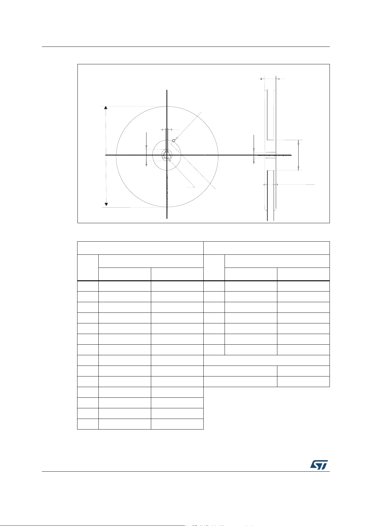
Figure 21. Reel for DPAK (TO-252)
Table 9. DPAK (TO-252) tape and reel mechanical data
Tape Reel
mm
Dim.
Dim.
Min. Max. Min. Max.
A0 6.8 7 A 330
B0 10.4 10.6 B 1.5
B1 12.1 C 12.8 13.2
D 1.5 1.6 D 20.2
D1 1.5 G 16.4 18.4
E 1.65 1.85 N 50
F 7.4 7.6 T 22.4
K0 2.55 2.75
P0 3.9 4.1 Base qty. 2500
P1 7.9 8.1 Bulk qty. 2500
P2 1.9 2.1
R40
T 0.25 0.35
mm
W 15.7 16.3
14/24 DocID022967 Rev 5
Page 15

STD10P6F6, STF10P6F6, STP10P6F6, STU10P6F6 Package information
7012510_Rev_K_B
4.3 TO-220FP package information
Figure 22. TO-220FP package outline
DocID022967 Rev 5 15/24
24
Page 16

Package information STD10P6F6, STF10P6F6, STP10P6F6, STU10P6F6
Table 10. TO-220FP mechanical data
mm
Dim.
Min. Typ. Max.
A4.4 4.6
B2.5 2.7
D2.5 2.75
E 0.45 0.7
F0.75 1
F1 1.15 1.70
F2 1.15 1.70
G 4.95 5.2
G1 2.4 2.7
H10 10.4
L2 16
L3 28.6 30.6
L4 9.8 10.6
L5 2.9 3.6
L6 15.9 16.4
L7 9 9.3
Dia 3 3.2
16/24 DocID022967 Rev 5
Page 17

STD10P6F6, STF10P6F6, STP10P6F6, STU10P6F6 Package information
BW\SH$B5HYB7
4.4 TO-220 package information
Figure 23. TO-220 type A package outline
DocID022967 Rev 5 17/24
24
Page 18

Package information STD10P6F6, STF10P6F6, STP10P6F6, STU10P6F6
Table 11. TO-220 type A mechanical data
mm
Dim.
Min. Typ. Max.
A4.40 4.60
b0.61 0.88
b1 1.14 1.70
c0.48 0.70
D 15.25 15.75
D1 1.27
E 10 10.40
e2.40 2.70
e1 4.95 5.15
F1.23 1.32
H1 6.20 6.60
J1 2.40 2.72
L13 14
L1 3.50 3.93
L20 16.40
L30 28.90
∅
P3.75 3.85
Q2.65 2.95
18/24 DocID022967 Rev 5
Page 19

STD10P6F6, STF10P6F6, STP10P6F6, STU10P6F6 Package information
0068771_L
4.5 IPAK package information
Figure 24. IPAK (TO-251) type A package outline
DocID022967 Rev 5 19/24
24
Page 20

Package information STD10P6F6, STF10P6F6, STP10P6F6, STU10P6F6
Table 12. IPAK (TO-251) type A mechanical data
mm.
DIM
min. typ. max.
A 2.20 2.40
A1 0.90 1.10
b 0.64 0.90
b2 0.95
b4 5.20 5.40
B5 0.30
c 0.45 0.60
c2 0.48 0.60
D 6.00 6.20
E 6.40 6.60
e2.28
e1 4.40 4.60
H16.10
L 9.00 9.40
L1 0.80 1.20
L2 0.80 1.00
V1 10°
20/24 DocID022967 Rev 5
Page 21

STD10P6F6, STF10P6F6, STP10P6F6, STU10P6F6 Package information
7\SH&5HY/
Figure 25. IPAK (TO-251) type C package outline
DocID022967 Rev 5 21/24
24
Page 22

Package information STD10P6F6, STF10P6F6, STP10P6F6, STU10P6F6
Table 13. IPAK (TO-251) type C mechanical data
mm
Dim.
min. typ. max.
A 2.20 2.30 2.35
A1 0.90 1.00 1.10
b 0.66 0.79
b2 0.90
b4 5.23 5.33 5.43
c 0.46 0.59
c2 0.46 0.59
D 6.00 6.10 6.20
D1 5.20 5.37 5.55
E 6.50 6.60 6.70
E1 4.60 4.78 4.95
e 2.20 2.25 2.30
e1 4.40 4.50 4.60
H 16.18 16.48 16.78
L 9.00 9.30 9.60
L1 0.80 1.00 1.20
L2 0.90 1.08 1.25
θ13°5°7°
θ21°3°5°
22/24 DocID022967 Rev 5
Page 23

STD10P6F6, STF10P6F6, STP10P6F6, STU10P6F6 Revision history
5 Revision history
Table 14. Document revision history
Date Revision Changes
10-May-2012 1 First release.
20-Jun-2012 2
Updated title on the cover page.
Updated all parameter values in Table 5, Table 6 and Figure 1.
– Added: TO-220FP and IPAK packages
17-May-2013 3
– Updated: R
and 7 typical values
value in cover page, R
DS(on)
– Updated mechanical data only for DPAK in Section 4: Package
information
– Updated: Figure 2 and 3
24-Apr-2014 4
– Updated: Section 4.1: DPAK package informati on and Section4.4:
TO-220 package information
– Minor text changes
– All voltage and current polarities inverted
27-Jul-2015 5
– Added: note in Section 2.1: Electrical characteristics (curves)
– Updated: Section 4.1 and Section 4.5
– Text and formatting changes throughout document
values, Table 5, 6
thj-case
DocID022967 Rev 5 23/24
24
Page 24

STD10P6F6, STF10P6F6, STP10P6F6, STU10P6F6
IMPORTANT NOTICE – PLEASE READ CAREFULLY
STMicroelectronics NV and it s subsidiaries (“ST”) reserve the right to make changes, corrections, enhancements, modifications, and
improvements to ST produc ts and /or to this document at any time witho ut notice. Purchasers should obt ain the lat est relevan t info rmation on
ST products before placing orders. ST products are sold pursuant to ST’s terms and conditions of sale in place at the time of order
acknowledgement.
Purchasers are solely r espon si ble for t he cho ic e, s elect ion, a nd use of ST produc ts and ST assume s no l iabil ity f or app lication as sist ance or
the design of Purchasers’ products.
No license, express or implied , to any intellectual property right is granted by ST herein.
Resale of ST products with provis ions different from the infor m ation set forth herein shall void any warranty gra nted by ST for such product.
ST and the ST logo are trademarks of ST. All other product or service names are the property of their respective owners.
Information in this document supers edes and replaces information previously sup plied in any prior versions of this document.
© 2015 STMicroelectronics – All rights reserved
24/24 DocID022967 Rev 5
 Loading...