

Page 1

SPSGRFC
Sub1GHz (433 or 868 or 915 MHz) programmable transceiver module
August 2016 - rev 0.1
This is preliminary information on a new product now in development or undergoing evaluation. Details are
subject to change without notice. www.st.com
www.st.com
Preliminary Datasheet
Features
Programmable Radio features
- Modulation schemes: 2-FSK, GFSK,
MSK, GMSK, OOk, ASK
- Air data rate from 1 to 500 kbps
- On board UFL connector for external
antenna
- Operating temperature range from -40 °C
to 85°C
RF features
- Receiver sensitivity: -118 dBm
- Programmable RF output power up to +16
dBm
Host Interface
- SPI
General I/O
- Up to 32 programmable I/O functions on 4
GPIO programmable module pins
Three Carrier Frequency versions
- 433 MHz for externally tuned antenna
- 868 MHz for externally tuned antenna
- 915 MHz for externally tuned antenna
Preliminary module picture
11.5 mm x 13.5 mm x 2.0 mm
Page 2

SPSGRFC
1 Description
The SPSGRFC is an easy to use Sub1GHz transceiver module, with many
programmable features. The module provides a complete RF platform in a tiny form
factor.
The SPSGRFC enables electronic devices with wireless connectivity, not requiring any
RF experience or expertise for integration into the final product. The SPSGRFC, being a
certified solution, optimizes the time to market of the final applications.
The module is designed for maximum performance in a minimal space including 4
programmable I/O pin and SPI serial interface.
2 Applications
AMR (automatic meter reading)
Home and building automation
WSN (wireless sensors network)
Industrial monitoring and control
Wireless fire and security alarm systems
Point-to-point wireless link
P a g e | 2 Rev 0.1
Page 3

SPSGRFC
UFL RF connector
for external antenna
Battery or External Supply
SPI LINE
M.C.U. clock
SPSGRF-xxx Module - 2016
SUPPLY FILTER
Bead Ferrite
RF
BALUN
+ Filter
50 MHz
Crystal
868 MHz or 915 MHz
or 433 MHz
EXTERNAL ANTENNA
I/O
SPIRIT1
DEVICE
RF
TUNING
NETWORK
Programmable
I/O
Host Controller
interface
3 Block Diagram
Figure 1 – Block Diagram
Rev 0.1 P a g e | 3
Page 4

SPSGRFC
4 Short description of the module functional behaviour
The SPIRIT1 device inside the SPSGRFC module is provided with a built-in main controller which controls
the switching between the two main operating modes: transmit (TX) and receive (RX).
In shutdown condition the SPSGRFC module can be switched on/off with the external pin SDN, all other
functions/registers/commands are available through the SPI interface and GPIOs. No internal supply is
generated (in order to have minimum battery leakage), and hence, all stored data and configurations are lost.
The GPIO and SPI ports of the module during SHUTDOWN are in HiZ. From shutdown state, the SPSGRFC
module can be switched on from the SDN pin and goes into READY state, which is the default, where the
reference signal from XO is available.
From READY state, the SPSGRFC module can be moved to LOCK state to generate the high precision LO
signal and/or TX or RX modes. Switching from RX to TX and vice versa can happen only by passing through
the LOCK state. This operation is normally managed by radio control with a single user command (TX or RX).
At the end of the operations above, the SPSGRFC module can return to its default state (READY) and can
then be put into a sleeping condition (SLEEP state), having very low power consumption.
If no timeout is required, the SPSGRFC module can be moved from READY to STANDBY state, which has
the lowest possible current consumption while retaining FIFO, status and configuration registers. To manage
the transitions towards and between these operating modes, the controller works as a state machine, whose
state switching is driven by SPI commands.
Figure 2 - Module functional states transitions diagram
P a g e | 4 Rev 0.1
Page 5

Rating
Min
Typical
Max
Unit
Storage temperature range
-40 - +85
°C
Supply voltage, VIN
-0.3 - + 3.9
Volts
I/O pin Voltage
-0.3 - + 3.9
Volts
RF saturation input power
-
10
-
dBm
Rating
Min
Typical
Max
Unit
Operating Temperature Range
-40 - 85
°C
Supply Voltage VIN
1.8
3.3
3.6
Volts
Signals & I/O Pin Voltage
(according Supply Voltage)
1.8 - 3.6
Volts
RF Frequency Bandwidth
(SPSGRFC-433)
433.050
434.790
MHz
RF Frequency Bandwidth
(SPSGRFC-868)
863 870
MHz
RF Frequency Bandwidth
(SPSGRFC-915)
902 928
MHz
5 Hardware Specifications
General Conditions (VIN= 3.3V and 25°C)
5.1 Absolute Maximum Ratings
Table 1 - Absolute Maximum Ratings
5.2 Recommended Operating Conditions
Table 2 - Recommended Operating Conditions
Rev 0.1 P a g e | 5
Page 6

SPSGRFC
Symbol
Parameter
Test conditions
Max
Unit
Idd
Supply
current
Operating mode
Tx, +11.6 dBm, 2-FSK, 433 MHz
22
mA
Operating mode
Tx, -7 dBm, 2-FSK, 433 MHz
9
mA
Operating mode Rx, 433 MHz
10
mA
Command mode
0.6
mA
Shutdown high level Vdd
With other I/O in High impedance
0.1
µA
Symbol
Parameter
Test conditions
Max
Unit
Idd
Supply
current
Operating mode
Tx, +11.6 dBm, 2-FSK, 868 MHz
22
mA
Operating mode
Tx, -7 dBm, 2-FSK, 868 MHz
9
mA
Operating mode Rx, 868 MHz
10
mA
Command mode
0.6
mA
Shutdown high level Vdd
With other I/O in High impedance
0.1
µA
Symbol
Parameter
Test conditions
Max
Unit
Idd
Supply
current
Operating mode
Tx, +11.6 dBm, 2-FSK, 915 MHz
22
mA
Operating mode
Tx, -7 dBm, 2-FSK, 915 MHz
9
mA
Operating mode Rx, 915 MHz
10
mA
Command mode
0.6
mA
Shutdown high level Vdd
With other I/O in High impedance
0.1
µA
5.3 Module current consumption
Table 3 – SPSGRFC-433 module current consumption
Table 4 – SPSGRFC-868 module current consumption
Table 5 – SPSGRFC-915 module current consumption
P a g e | 6 Rev 0.1
Page 7

Name
Type
Pin #
Description
ALT Function
V max. Tolerant
Initial State
SPI Interface
SPI_CLK
I
7
SPI CLOCK (Max. 8 MHz)
Vin
SPI_MISO
O
8
SPI MISO (MASTER in / SLAVE out)
Vin
SPI_MOSI
I
9
SPI MOSI (MASTER out SLAVE in)
Vin
SPI_CS
I
10
SPI “Chip Select” (SPI slave select)
Vin
Power and Ground
Vin
5
Vin
(1.8V + 3.6V max.)
GND
6
GND
Module SHUTDOWN
SDN
I
11
SHUTDOWN input (active high)
(1.8V + 3.6V max.).
GPIO – General Purpose Input/Output
GPIO [0]
I/O
4
Programmable Input / Output
& Analog Temperature output
(1.8V + Vin max.).
Digital Output.
Low Power
GPIO [1]
I/O
3
Programmable Input / Output
(1.8V + Vin max.).
Digital Output.
Low Power
GPIO [2]
I/O
2
Programmable Input / Output
(1.8V + Vin max.).
Digital Output.
Low Power
GPIO [3]
I/O
1
Programmable Input / Output
(1.8V + Vin max.).
Digital Output.
Low Power
Optional External Antenna connections (Not available on the standard SPSGRFC-xxx modules)
N.C.
N.C
12
Not connected
N.C.
N.C.
13
Not connected
N.C.
N.C.
14
Not connected
5.4 Pin Assignement
Figure 3 – Pin connection diagram
Table 6 – Pin Assignment
Rev 0.1 P a g e | 7
Page 8

SPSGRFC
6 Mechanical dimensions
Figure 4 – Mechanical Dimensions
Figure 5 – Recommend land pattern
P a g e | 8 Rev 0.1
Page 9

Modulation
Standards
Parameter
Max.
Unit
2-FSK
GFSK
MSK
FCC Part 15.207 (1)
FCC Part 15.247 (1)
IC RSS-210 (1)
EN 300 220-2 V2.4.1
EN301 489-01 V1.9.2
EN301 489-03 V1.4.1
Data Rate
500
kbps
Output
power
+11.6
dBm
OOK
ASK
FCC Part 15.207 (1)
FCC Part 15.247 (1)
IC RSS-210 (1)
Data Rate
250
kbps
Output
power
+4
dBm
7 Hardware design
SPSGRFC module supports SPI hardware interfaces.
Notes
All unused pins should be left floating; do not ground.
All GND pins must be well grounded.
The area around the module should be free of any ground planes, power planes, trace
routings, or metal for 6 mm from the module antenna position, in all directions.
Traces should not be routed underneath the module.
7.1 Modules RF compliance limits
The RF compliance limits are those tested for FCC, IC and CE certification using the dedicated
dongle (PC92A.V01). These limits are enforced by the dongle firmware. Care must be taken with
custom application firmware to ensure these limits are not exceeded, voiding the FCC, IC and CE
certification.
(1) FCC and IC standards are applicable only to the SPSGRFC-915 module.
Rev 0.1 P a g e | 9
Table 7. RF compliance limits table
Page 10

SPSGRFC
8 Module user firmware short description
For more user firmware information, please refer to the SPIRIT1 Datasheet - October 2016
DocID022758 Rev 10.
Downloadable at the following link: www.st.com/resource/en/datasheet/bluenrg-1.pdf
The following are short firmware notes, useful to furnish to the user a condensed view of the many
programming ways of the SPSGRFC-xxx module. (The following “Register table” refers the SPIRIT1
datasheet, so the table numbers and the links into the table are referred to the same document).
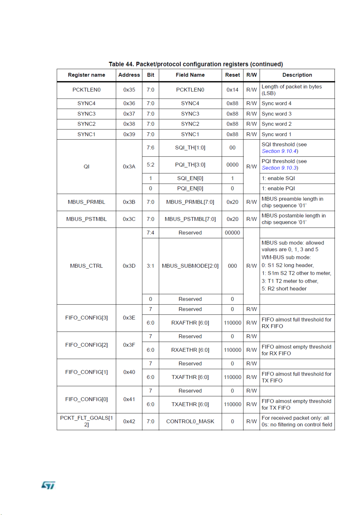
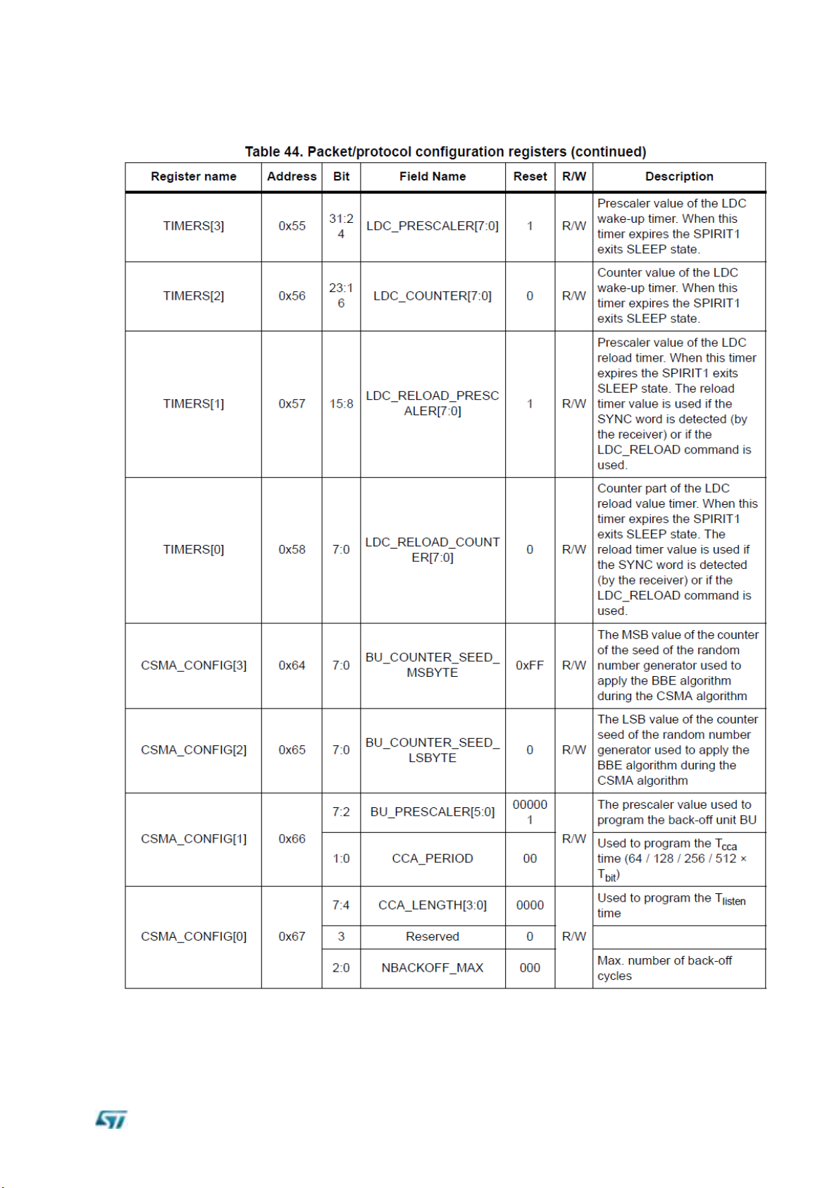
Register table
This section describes all the registers used to configure the SPIRIT1 device, assembled into the module.
The description is structured in sections according to the register usage.
SPIRIT1 has three types of registers:
Read and write (R/W), which can be completely managed by SPI using READ and
WRITE operations
Read-only (R)
Read-and-reset (RR), is automatically cleared after a READ operation.
A further category of special registers collects the ones which cannot be categorized in any
of the three mentioned above R/W, R, or RR.
The fields named as “Reserved” must not be overridden by the user, otherwise, behavior is
not guaranteed.
The memory map is shown in the following table:
P a g e | 10 Rev 0.1
Page 11

Rev 0.1 P a g e | 11
Page 12

SPSGRFC
P a g e | 12 Rev 0.1
Page 13

Rev 0.1 P a g e | 13
Page 14

SPSGRFC
P a g e | 14 Rev 0.1
Page 15

Rev 0.1 P a g e | 15
Page 16

SPSGRFC
P a g e | 16 Rev 0.1
Page 17

Rev 0.1 P a g e | 17
Page 18

SPSGRFC
P a g e | 18 Rev 0.1
Page 19
Rev 0.1 P a g e | 19
Page 20

SPSGRFC
P a g e | 20 Rev 0.1
Page 21

Rev 0.1 P a g e | 21
Page 22

SPSGRFC
P a g e | 22 Rev 0.1
Page 23
Rev 0.1 P a g e | 23
Page 24

SPSGRFC
P a g e | 24 Rev 0.1
Page 25

Rev 0.1 P a g e | 25
Page 26

SPSGRFC
P a g e | 26 Rev 0.1
Page 27

Rev 0.1 P a g e | 27
Page 28

SPSGRFC
Comment
FCC ID
S9NSPSGRFC
With external “TAOGLASS” antenna and UFL to SMA connector RF cable
version
IC ID
8976C-SPSGRFC
With external “TAOGLASS” antenna and UFL to SMA connector RF cable
version
ETSI
Compliant
Approved with external “LINX” antenna and UFL to SMA cable version
9 Regulatory compliance
RF compliance
The RF certifications obtained are described in Table 8 below.
Table 8. RF certification summary
This radio transmitter IC ID 8976-SPSGRFC has been approved by Industry Canada to
operate with the antenna types listed below with the maximum permissible gain indicated.
Antenna types not included in this list, having a gain greater than the maximum gain
indicated for that type, are strictly prohibited for use with this device.
Note: The “TI.19.2113” antenna from “TAOGLASS” is the only approved antenna using the u.fl
connector version.
(Please, see the A.1 at the bottom of this document for the French translation).
The following are the main features of the antennas approved during the certification RF
test procedures, dedicated to SPSGRFC modules.
P a g e | 28 Rev 0.1
Page 29

For the SPSGRFC-915 module the approved antenna is the TAOGLASS TI.19.2113
*Note all data provided in this table are based on the “TAOGLASS TI.19.2113” reference documentation.
Rev 0.1 P a g e | 29
Page 30

SPSGRFC
For the SPSGRFC-868 module the approved antenna is the LINX ANT-868-CW-QW
*Note all data provided in this table are based on the “LINX - ANT-868-CW-QW” reference ground plane.
P a g e | 30 Rev 0.1
Page 31

For the SPSGRFC-433 module the approved antenna is the LINX ANT-433-CW-QW
*Note all data provided in this table are based on the “LINX - ANT-433-CW-QW” reference ground plane.
Rev 0.1 P a g e | 31
Page 32

SPSGRFC
FCC and IC
This module has been tested and complies with the FCC part 15 and IC RSS-247
regulations. These limits are designed to provide reasonable protection against harmful
interference in approved installations. This equipment generates, uses, and can radiate
radio frequency energy and, if not installed and used in accordance with the instructions,
may cause harmful interference to radio communications.
However, there is no guarantee that interference will not occur in a particular installation.
This device complies with part 15 of the FCC rules. Operation is subject to the following two
conditions:
1.
The device must not cause harmful interference.
and
2.
The device must accept any interference received, including interference that may
cause undesired operation.
Modifications or changes to this equipment not expressly approved by the party responsible
for compliance may render void the user's authority to operate this equipment.
Modular approval, FCC and IC
- FCC ID: S9NSPSGRFC
- IC: 8976C-SPSGRFC
In accordance with FCC part 15, the module SPSGRFC-915 is listed above as a modular transmitter
device.
This module and the corresponding antenna are evaluated for stand-alone use only. Finished products
incorporating multiple transmitters must comply with collocation and RF exposure requirements in
accordance with FCC multi-transmitter product procedures. Collocated transmitters operating in portable
RF exposure conditions (e.g. <20 cm from persons including but not limited to body worn and hand-held
devices) may require separate approval.
Labeling instructions
When integrating the SPSGRFC-915 into the final product, it must be ensured that the FCC
and IC labeling requirements specified below are satisfied. Based on the Public Notice from
FCC, the product into which the ST transmitter module is installed must display a label
referring to the enclosed module. The label should use wording like the following:
Contains Transmitter Module
- FCC ID: S9NSPSGRFC
- IC: 8976C-SPSGRFC
Any similar wording that expresses the same meaning may also be used.
P a g e | 32 Rev 0.1
Page 33

CE compliance
This module complies with the following European EMI/EMC and safety directives and
standards:
– ETSI EN 300 328 V1.8.1:2012
– EN 301 489-1 V1.9.2:2011 + EN 301 489-17 V2.2.1:2009
– EN 60950-1:2006 + A11:2009 + A1:2010 + A12:2011 + A2:2013
– EN 62479:2010
Figure 3. CE certified
Rev 0.1 P a g e | 33
Page 34

SPSGRFC
10 Reflow soldering
The SPSGRFC is a surface mount Sub1GHz Transceiver module supplied on a 11 pin, 4-layer
PCB. The final assembly recommended reflow profiles are indicated here below.
Soldering phase has to be executed with care: In order to avoid undesired melting phenomenon,
particular attention has to be taken on the set up of the peak temperature.
Here following some suggestions for the temperature profile based on IPC/JEDEC J-STD-020C,
July 2004 recommendations.
Table 4 – Soldering
Figure 6 – Soldering profiles
P a g e | 34 Rev 0.1
Page 35

Order code
Description
Packing
MOQ
SPSGRFC-433
433 MHz Spirit1 transceiver module (Region 1,Europe)
Jedec
tray
2’448 pcs
SPSGRFC-868
868 MHz Spirit1 transceiver module (Region 1,Europe)
Jedec
tray
2’448 pcs
SPSGRFC-915
915 MHz Spirit1 transceiver module (Region 2,The
Americas)
Jedec
tray
2’448 pcs
11 RoHS compliance
ST Bluetooth modules comply with the ECOPACK2 level of RoHS compliance grade.
12 Ordering Information
Table 5 – Ordering Information
13 Traceability
Each module is univocally identified by serial number stored in a 2D data matrix laser
marked on the bottom side of the module itself.
The serial number has the following format:
WW YY D FF NNN
where
WW = week
YY = year
D = product ID family
FF = production panel coordinate identification
NNN = progressive serial number.
Each module bulk is identified by a bulk ID.
BULK ID and module 2D data matrix are linked by a reciprocal traceability link.
The module 2D data matrix traces the lot number of any raw material used.
Rev 0.1 P a g e | 35
Page 36

SPSGRFC
Déclaration de conformité
A.1 Certification FCC
Le module SPSGRFC-915 a été testé et déclaré conforme avec la section 15 de la
Règlementation FCC. Ces limitations sont stipulées afin de procurer une protection
raisonnable contre les interférences gênantes dans les installations approuvées. Cet
appareil génère, utilise et diffuse des ondes radio et, s’il n’est pas installé et utilisé en
conformité avec les instructions dont il fait l’objet, peut causer des interférences gênantes sur
les communications radio.
Il n’y a cependant pas de garantie qu’une interférence ne se produira pas dans une
installation particulière.
Cet appareil est en conformité avec la section 15 des règlements FCC. L’utilisation est
soumise aux deux conditions suivantes: (1) cet appareil ne doit pas causer d'interférences
nocives, et (2) Cet appareil doit supporter toute interférence reçue, y compris des
A.1.1 Instructions d'étiquetage
(2) Cet appareil doit supporter toute interférence reçue, y compris des interférences qui peuvent provoquer
un fonctionnement non désiré.
interférences qui peuvent provoquer un fonctionnement non désiré.
Tout changement ou modification fait(e) à cet appareil et non expressément approuvé(e)
par STMicroelectronics peut annuler l’autorisation pour l’utilisateur de faire fonctionner
l’appareil.
Approbation du module
FCC ID: S9NSPSGRFC
Conformément à la section 15 des règlements FCC, le module SPSGRFC-915 est répertorié
comme un dispositif émetteur modulaire.
Ce module n’est évalué que pour une utilisation autonome. Les produits finis incorporant
plusieurs émetteurs doivent être conformes à la colocation et aux exigences d'exposition
RF en concordance avec les procédures FCC multi-émetteurs. D’autres émetteurs
fonctionnant dans des dispositifs portables exposés aux RF (par exemple, situés à moins de
20 cm des personnes avec dispositifs portatifs ou portés contre le corps) peuvent nécessiter
d'une approbation séparée.
Lors de l'intégration du module SPSGRFC-915 dans le produit final, le fabricant doit
s’assurer que les exigences en matière d'étiquetage de la FCC sont satisfaites. Une
déclaration doit être placée sur l’étiquette extérieure du produit final indiquant que le produit
comprend un module certifié. L'étiquette doit comporter les informations suivantes (ou une
mention analogue que recouvre la même notion):
Contient FCC ID: S
OU
Ce produit contient FCC ID: S9NSPSGRFC
Le sous-traitant doit inclure les énoncés suivants sur l’étiquette extérieure du produit final à
moins que le produit ne soit trop petit (par exemple moins de 4 x 4 pouces):
Cet appareil est en conformité avec la section 15 des règlements FCC. L’utilisation est
soumise aux deux conditions suivantes:
(1) cet appareil ne doit pas causer d'interférences nocives, et
9NSPSGRFC
P a g e | 36 Rev 0.1
Page 37

A.1.2 Instructions pour l’utilisation du produit
La présente section concerne les produits finis contenant le module SPSGRFC-915,
assujettis aux normes FCC. Le manuel du produit final doit contenir la déclaration suivante
(ou une mention analogue que recouvre la même notion):
“ Avertissement: Les changements ou modifications non expressément approuvés par la
partie responsable de la conformité pourraient annuler l'autorisation de l'utilisateur de faire
fonctionner cet équipement. (Section 15.21)”
Dans le cas où le produit finis d’un fabriquant OEM rentre dans les limites de la Classe
B (résidentiel), les énoncés suivants doivent être inclus dans le manuel du produit
finis:
“Remarque : Cet équipement a été testé et déclaré conforme aux limitations prévues dans le
cadre de la classe B des appareils numériques, définies par la section 15 du règlement de la
FCC. Ces limites sont conçues pour fournir une protection raisonnable contre toute
interférence dangereuse issue d'une installation résidentielle. Cet équipement produit,
utilise et peut émettre de l'énergie radio électrique et, s'il n'est pas installé et utilisé
conformément aux présentes instructions, peut causer des interférences nuisibles aux
communications radio. Cependant, il se peut que des interférences se produisent dans une
installation particulière. Si cet appareil cause des interférences nuisibles à la réception des
signaux de radio ou de télévision, ce qui peut être déterminé en allumant et en éteignant
l'appareil, on encourage l'utilisateur d'essayer de corriger ces interférences par l'un des
moyens suivants:
– Réorienter ou repositionner l'antenne de réception.
– Augmenter la distance séparant l’équipement du récepteur.
– Connecter l’équipement à une prise appartenant à un circuit différent de celui sur
lequel le récepteur est connecté.
– Consulter le revendeur ou un technicien radio/TV expérimenté pour obtenir de l’aide.”
Dans le cas où le produit fini d’un sous-traitant rentre dans les limites imposées aux
appareils numériques de classe A, les énoncés suivants doivent être inclus dans le
manuel du produit finis:
“REMARQUE : Cet appareil a été testé et certifié conforme aux spécifications d'un appareil
électronique de classe A (class A digital device), conformément à la partie 15 du règlement
de la FCC. Ces contraintes sont destinées à fournir une protection raisonnable contre les
interférences nuisibles quand l'appareil est utilisé dans une installation commerciale. Cet
équipement produit, utilise et peut émettre de l'énergie radio électrique et, s'il n'est pas
installé et utilisé conformément aux présentes instructions, peut causer des interférences
nuisibles aux communications radio. L'utilisation de cet appareil dans une installation
résidentielle peut entraîner des interférences nuisibles et l'utilisateur devra corriger les
interférences à ses propres frais.”
Rev 0.1 P a g e | 37
Page 38

SPSGRFC
A.2 Certification IC
Le module SPSGRFC-915 a été testé et déclaré conforme avec la Règlementation IC
CNR-210. Ces limitations sont stipulées afin de procurer une protection raisonnable contre
les interférences gênantes en installations approuvées. Cet appareil génère, utilise et
diffuse des ondes radio et, s’il n’est pas installé et utilisé en conformité avec les instructions
dont il fait l’objet, peut causer des interférences gênantes sur les communications radio.
Il n’y a cependant pas de garantie qu’une interférence ne se produira pas dans une
installation particulière.
Ce produit répond aux exigences de la norme CNR-210 d'Industrie Canada. Son
fonctionnement est soumis aux deux conditions suivantes:
(1) cet appareil ne doit pas causer d'interférences nocives, et
(2) Cet appareil doit supporter toute interférence reçue, y compris des interférences qui
peuvent provoquer un fonctionnement non désiré.
Tout changement ou modification fait(e) à cet appareil et non expressément approuvé(e)
par STMicroelectronics peut annuler l’autorisation pour l’utilisateur de faire fonctionner
l’appareil.
(a)
Approbation du module
IC: 8976C-SPSGRFC
Conformément à IC CNR-210, le module SPSGRFC-915 est répertorié comme un dispositif
émetteur modulaire
Ce module n’est évalué que pour une utilisation autonome. Les produits finis incorporant
plusieurs émetteurs doivent être conformes à la colocation et aux exigences d'exposition
RF en concordance avec les procédures FCC multi-émetteurs. D’autres émetteurs
fonctionnant dans des dispositifs portables exposés aux RF (par exemple, situés à moins de
20 cm des personnes avec dispositifs portatifs ou portés contre le corps) peuvent nécessiter
d'une approbation séparée.
A.2.1 Instructions d'étiquetage
Lors de l'intégration du module SPSGRFC-915 dans le produit final, le fabricant doit
s’assurer que les exigences en matière d'étiquetage de la IC sont satisfaites. Une
déclaration doit être placée sur l’étiquette extérieure du produit final indiquant que le produit
comprend un module certifié. L'étiquette doit comporter les informations suivantes (ou une
mention analogue que recouvre la même notion):
Contient IC ID: 8976C-SPSGRFC
OU
Ce produit contient
Le sous-traitant doit inclure les énoncés suivants sur l’étiquette extérieure du produit final à
moins que le produit ne soit trop petit (par exemple moins de 4 x 4 pouces):
Cet appareil est en conformité aux normes IC. L’utilisation est soumise aux deux conditions
suivantes:
(1) cet appareil ne doit pas causer d'interférences nocives, et
(2) Cet appareil doit supporter toute interférence reçue, y compris des interférences qui
peuvent provoquer un fonctionnement non désiré
IC ID: 8976C-SPSGRFC
P a g e | 38 Rev 0.1
Page 39

A.2.2 Instructions pour l’utilisation du produit
La présente section concerne les produits finis contenant le module SPSGRFC-915,
assujettis aux normes IC. Le manuel du produit final doit contenir la déclaration suivante (ou
une mention analogue que recouvre la même notion):
“Avertissement: Les changements ou modifications non expressément approuvés par la
partie responsable de la conformité pourraient annuler l'autorisation de l'utilisateur de faire
fonctionner cet équipement. (CNR-210)”
Dans le cas où le produit finis d’un fabriquant OEM rentre dans les limites de la Classe
B (résidentiel), les énoncés suivants doivent être inclus dans le manuel du produit finis:
“ Remarque : Cet équipement a été testé et déclaré conforme aux limitations prévues dans le
cadre de la classe B des appareils numériques, définies par la norme CNR-210 d'Industrie
Canada.
Ces limites sont conçues pour fournir une protection raisonnable contre toute interférence
dangereuse issue d'une installation résidentielle. Cet équipement produit, utilise et peut
émettre de l'énergie radio électrique et, s'il n'est pas installé et utilisé conformément aux
présentes instructions, peut causer des interférences nuisibles aux communications radio.
Cependant, il se peut que des interférences se produisent dans une installation particulière.
Si cet appareil cause des interférences nuisibles à la réception des signaux de radio ou de
télévision, ce qui peut être déterminé en allumant et en éteignant l'appareil, nous
encourageons l'utilisateur à essayer de corriger ces interférences par l'un des moyens
suivants:
– Réorienter ou repositionner l'antenne de réception.
– Augmenter la distance séparant l’équipement du récepteur.
– Connecter l’équipement à une prise appartenant à un circuit différent de celui sur
lequel le récepteur est connecté.
– Consulter le revendeur ou un technicien radio/TV expérimenté pour obtenir de l’aide.”
Dans le cas où le produit finis d’un fabriquant OEM rentre dans le cadre des limites imposées
aux appareils numériques de classe A, les énoncés suivants doivent être inclus dans le
manuel du produit finis:
“ REMARQUE: Cet appareil a été testé et certifié conforme aux spécifications d'un appareil
électronique de classe A (class A digital device), conformément à la norme CNR-210
d'Industrie Canada. Ces contraintes sont destinées à fournir une protection raisonnable
contre les interférences nuisibles quand l'appareil est utilisé dans une installation
commerciale. Cet équipement produit, utilise et peut émettre de l'énergie radio électrique et,
s'il n'est pas installé et utilisé conformément aux présentes instructions, peut causer des
interférences nuisibles aux communications radio. L'utilisation de cet appareil dans une
installation résidentielle peut entraîner des interférences nuisibles et l'utilisateur devra corriger
les interférences à ses propres frais.”
Rev 0.1 P a g e | 39
Page 40

SPSGRFC
A.3 Certification CE
Le module SPSGRFC a obtenu une certification de conformité aux normes suivantes:
– EN 300 328 V1.8.1 :2012
– EN 300 328 V1.9.1 :2015
– EN 301 489-17 V2.2.1 :2009
– EN 301 489-1 V1.9.2:2011
– EN 62479 :2010
– EN60950-1:2006 + A11:2009 + A1:2010 + A12:2011 + A2 :2013
Le module est certifié CE:
P a g e | 40 Rev 0.1
Page 41

A.4 Antennes certifiées
Pour le module SPSGRF-915 l'antenne approuvée est le Taoglas TI.19.2113
TI.19 est un 915MHz bande ISM dipôle antenne omnidirectionnelle haute performance.
La conception permet à l'antenne articulée à être positionnée le plus approprié à son
angle. Cette antenne dispose d'un SMA (M) de connecteur Fiche.
Pour un grand nombre d'applications d'antenne, telles que le Wi-Fi Hotspot ou Pico-cell
cellulaire, le
l'antenne de l'appareil de l'opérateur et l'antenne du dispositif à distance de l'utilisateur
ne sont pas sur le même plan horizontal. La TI.19 a été conçu avec un
diagramme de rayonnement en forme de papillon, pour aider à contrer cet effet.
Spécifications de l'antenne
Rev 0.1 P a g e | 41
Page 42

SPSGRFC
Pour le module SPSGRF-868 l'antenne approuvée est le LINX ANT-868-CW-QW
Les antennes CW série ¼ d'onde offrent exceptionnelle
la performance dans un boîtier robuste et esthétiquement attrayant. Ces antennes sont
disponibles avec SMA standard ou FCC Part 15 conformes connecteurs RP-SMA.
connecteurs RP-SMA permettent le remplacement facile sur le terrain tout en respectant
les exigences de la FCC. Une grande variété de connecteurs correspondant permet de
nombreuses options de montage.
P a g e | 42 Rev 0.1
Page 43

Caractéristiques
• À bas prix
• Performance excellente
• modèle Omni-directionnel
• Large bande passante
• Très faible ROS
• Entièrement intempérisés
• arbre principal flexible
• Robuste et résistante aux dommages
• SMA ou de la partie 15 connecteur RP-SMA conforme
• Utiliser avec du plastique * ou boîtiers métalliques
* Nécessite la proximité plan de masse
Spécifications électriques
Fréquence Centre: 868MHz
Recom. Fréq. Gamme: 750-950MHz
Wavelength: ¼ d'onde
Gain de crête: 1.6dBi
ROS: <1,9 typ. au centre
Impédance: 50 ohms
Connecteur: RP-SMA ou SMA
Oper. Temp. Plage: -40 ° C à + 90 ° C
les spécifications et les parcelles électriques mesurées sur 10,16 cm x 10,16 cm de plan
de masse (4,00 "x 4,00") de référence
Informations de commande
ANT-868-CW-QW (avec connecteur RP-SMA)
ANT-868-CW-QW-SMA (avec connecteur SMA)
Rev 0.1 P a g e | 43
Page 44

SPSGRFC
Pour le module SPSGRF-433 l'antenne approuvée est le LINX ANT-433-CW-QW
P a g e | 44 Rev 0.1
Page 45

Spécifications électriques
Fréquence Centre: 433MHz
Recmd. Fréq. Gamme: 400-470MHz
Wavelength: ¼ d'onde
Gain de crête: 3.3dBi
ROS: <1,9 typ. au centre
Impédance: 50 ohms
Connecteur: RP-SMA ou SMA
Oper. Temp. Plage: -40 ° C à + 90 ° C
Caractéristiques électriques et les parcelles mesurées sur 10,16 cm x
10,16 cm (4,00 "x 4,00") plan de masse de référence
Informations de commande
ANT-433-CW-QW (avec connecteur RP-SMA)
ANT-433-CW-QW-SMA (avec connecteur SMA)
Rev 0.1 P a g e | 45
Page 46

SPSGRFC
Please Read Carefully:
Information in this document is provided solely in connection with ST products. STMicroelectronics NV and its subsidiaries (“ST”) reserve
the right to make changes, corrections, modifications or improvements, to this document, and the products and services described herein
at any time, without notice.
All ST products are sold pursuant to ST’s terms and conditions of sale.
Purchasers are solely responsible for the choice, selection and use of the ST products and services described herein, and ST assumes
no liability whatsoever relating to the choice, selection or use of the ST products and services described herein.
No license, express or implied, by estoppel or otherwise, to any intellectual property rights is granted under this document. If any part of
this document refers to any third party products or services it shall not be deemed a license grant by ST for the use of such third party
products or services, or any intellectual property contained therein or considered as a warranty covering the use in any manner
whatsoever of such third party products or services or any intellectual property contained therein.
UNLESS OTHERWISE SET FORTH IN ST’S TERMS AND CONDITIONS OF SALE ST DISCLAIMS ANY EXPRESS OR IMPLIED
WARRANTY WITH RESPECT TO THE USE AND/OR SALE OF ST PRODUCTS INCLUDING WITHOUT LIMITATION IMPLIED
WARRANTIES OF MERCHANTABILITY, FITNESS FOR A PARTICULAR PURPOSE (AND THEIR EQUIVALENTS UNDER THE
LAWS OF ANY JURISDICTION), OR INFRINGEMENT OF ANY PATENT, COPYRIGHT OR OTHER INTELLECTUAL PROPERTY
RIGHT.
ST PRODUCTS ARE NOT DESIGNED OR AUTHORIZED FOR USE IN: (A) SAFETY CRITICAL APPLICATIONS SUCH AS LIFE
SUPPORTING, ACTIVE IMPLANTED DEVICES OR SYSTEMS WITH PRODUCT FUNCTIONAL SAFETY REQUIREMENTS; (B)
AERONAUTIC APPLICATIONS; (C) AUTOMOTIVE APPLICATIONS OR ENVIRONMENTS, AND/OR (D) AEROSPACE
APPLICATIONS OR ENVIRONMENTS. WHERE ST PRODUCTS ARE NOT DESIGNED FOR SUCH USE, THE PURCHASER SHALL
USE PRODUCTS AT PURCHASER’S SOLE RISK, EVEN IF ST HAS BEEN INFORMED IN WRITING OF SUCH USAGE, UNLESS A
PRODUCT IS EXPRESSLY DESIGNATED BY ST AS BEING INTENDED FOR “AUTOMOTIVE, AUTOMOTIVE SAFETY OR
MEDICAL” INDUSTRY DOMAINS ACCORDING TO ST PRODUCT DESIGN SPECIFICATIONS. PRODUCTS FORMALLY ESCC,
QML OR JAN QUALIFIED ARE DEEMED SUITABLE FOR USE IN AEROSPACE BY THE CORRESPONDING GOVERNMENTAL
AGENCY.
Resale of ST products with provisions different from the statements and/or technical features set forth in this document shall immediately
void any warranty granted by ST for the ST product or service described herein and shall not create or extend in any manner whatsoever,
any liability of ST.
ST and the ST logo are trademarks or registered trademarks of ST in various countries.
Information in this document supersedes and replaces all information previously supplied.
The ST logo is a registered trademark of STMicroelectronics. All other names are the property of their respective owners.
© 2014 STMicroelectronics - All rights reserved
STMicroelectronics group of companies
Australia - Belgium - Brazil - Canada - China - Czech Republic - Finland - France - Germany - Hong Kong - India - Israel - Italy - Japan -
Malaysia - Malta - Morocco - Philippines - Singapore - Spain - Sweden - Switzerland - United Kingdom - United States of America
www.st.com
P a g e | 46 Rev 0.1
 Loading...