

Page 1

AN5549
Application note
SPC5x Power PC Interrupts
Introduction
This document is intended for software and hardware developers who need to understand Interrupts, how to generate and
handle them for all cores integrated into SPC5x Automotive Microcontroller devices.
The main goal of this document is to clarify Interrupts management, and to provide reference codes to manage Interrupts as
well as the execution scenario.
This document also describes software and hardware interrupt management for External Interrupts.
AN5549 - Rev 1 - September 2020
For further information contact your local STMicroelectronics sales office.
www.st.com
Page 2
1 Interrupts and Exceptions
An interrupt is the action in which the processor saves its context (typically the machine state register [MSR] and
the next instruction address) and begins the execution at a predetermined interrupt handler address with a
modified MSR.
Core exception occurs when the flow of the execution is diverted, to allow the MCU to handle events generated
by internal or external sources. So the exceptions are generated by signals from internal and external peripherals,
instructions, the internal timer facility, debug events, or error conditions.
AN5549
Interrupts and Exceptions
1.1
Exceptions
When an exception is received, the Core saves its context and starts executing at a predetermined address.
Common types of exceptions are described in Table 1.
Table 1. Common Interrupt types
Exception types IVPR Offset
System Reset 0x00
Machine Check 0x10
Non-Maskable Input Interrupt 0x20
Critical Input Interrupt 0x30
External Input Interrupt 0x40
Performance Monitor Interrupts 0x50
Instruction Based Debug Interrupts 0x60
Debug Interrupt
Debug Imprecise Interrupt
Data Storage / Alignment Interrupts
Instruction Storage Interrupts
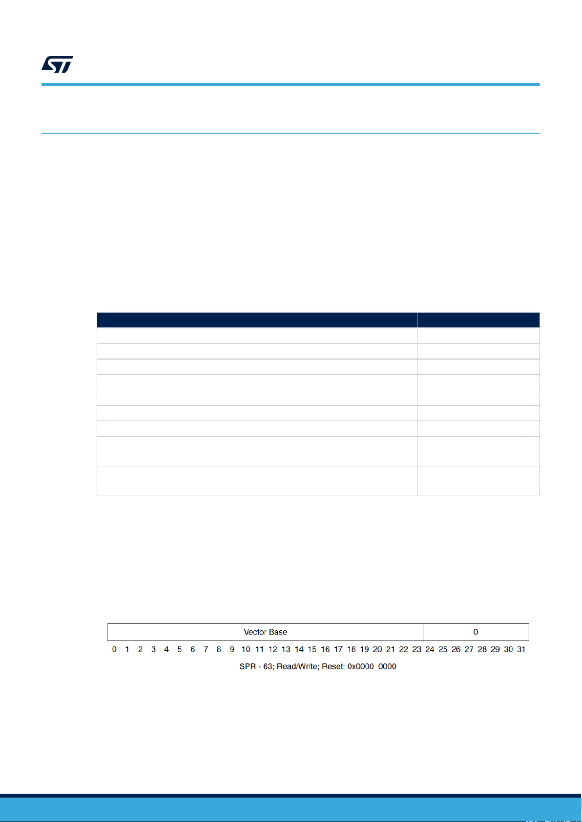
1.1.1 Interrupt Vector Prefix Registers (IVPR)
The Interrupt Vector Prefix Register is used during the exception processing for determining the starting address
of a software handler used to handle an exception.
The value of the Vector Offset selected for a specific exception type is concatenated with the Vector Base value
held in the Interrupt Vector Prefix register (IVPR) to form an instruction address from which execution is to begin.
The structure of the IVPR register is described in Figure 1 (more details can be found in the Reference Manuals
of specific devices).
0x70
0x80
AN5549 - Rev 1
Figure 1. Interrupt Vector Prefix Register
The description of the process for taking an exception is described in Figure 2.
page 2/15
Page 3
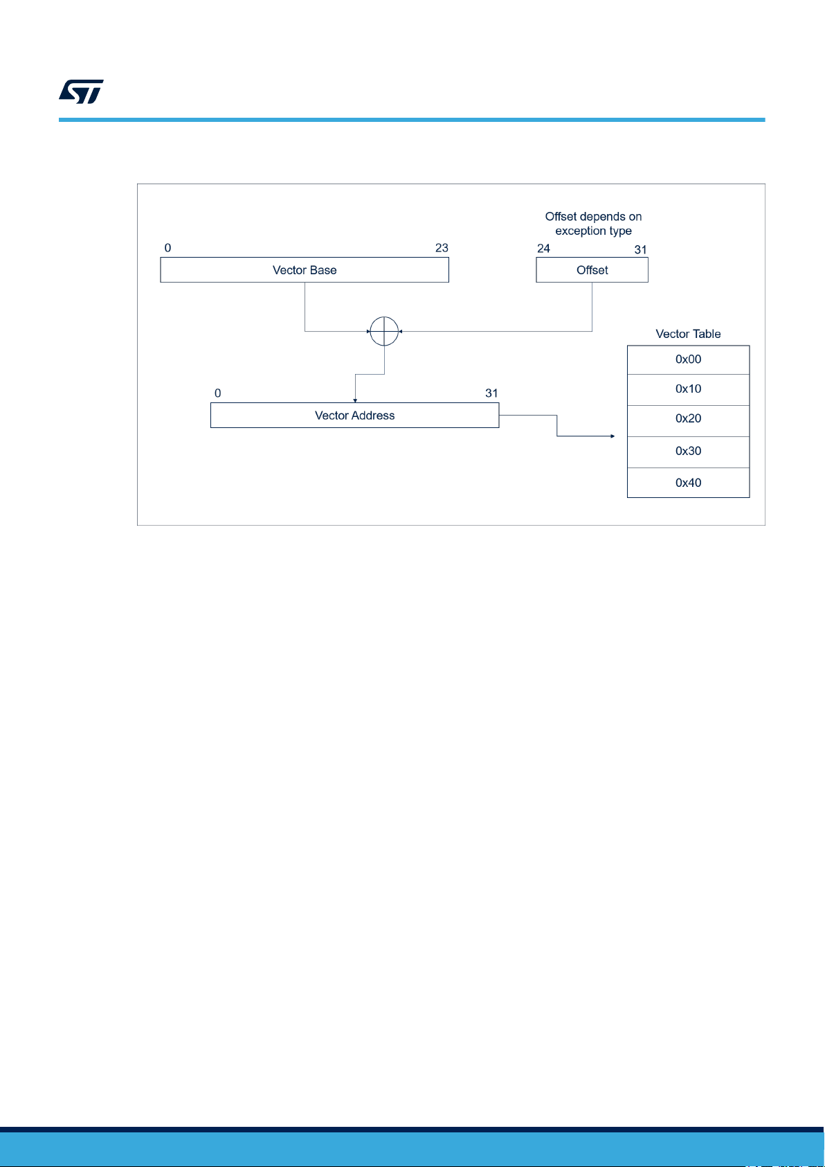
Figure 2. Process of taking an exception
AN5549
Interrupts
1.2 Interrupts
An interrupt is an exception that is signaled to the interrupt controller (INTC) and generated by a peripheral or by
the application code using software interrupts.
1.2.1 Interrupt Controller (INTC)
The interrupt controller is responsible to manage the interrupts generated by a peripheral.
Source of interrupts can be:
• Internal peripherals (embedded IPs e.g.[PC1] I2C, DSPI, SWT, etc.)
• External devices via microcontroller pins
The interrupt controller operates in two modes:
• Software vector mode
• Hardware vector mode
Selection of the operating mode is done by an enable bit (HVEN) in INTC Block Configuration Register (BRC)
• Software vector mode: BCR[HVENx] = 0
• Hardware vector mode: BCR[HVENx] = 1
where ‘x’ in HVEN bit is [0,1,2] to refer to Core_0, Core_1, Core_2 (if available).
AN5549 - Rev 1
page 3/15
Page 4
1.2.2 Software Vector Mode
In the software Vector Mode, as soon as a peripheral interrupt is raised, the External Interrupt Exception (offset
0x40) is generated. The code at offset 0x40 from IVPR is executed.
In order to take the interrupt, the code at offset 0x40 from IVPR should:
• Reserve appropriate space on the stack to save the Core context (PC, MSR, SRR0, SRR1, CR, LR, CTR,
XER, GPR0, …, GPR12)
• Read the INTC IACKR register to get the pointer to the software handler managing the specific peripheral
interrupt (ISR)
• Enable global interrupts (to allow nested interrupts)
• Jump to the ISR
• Disable global interrupts
• Acknowledge the interrupt on the interrupt controller (INTC)
• Restore the context
• Return from interrupt (to normal execution)
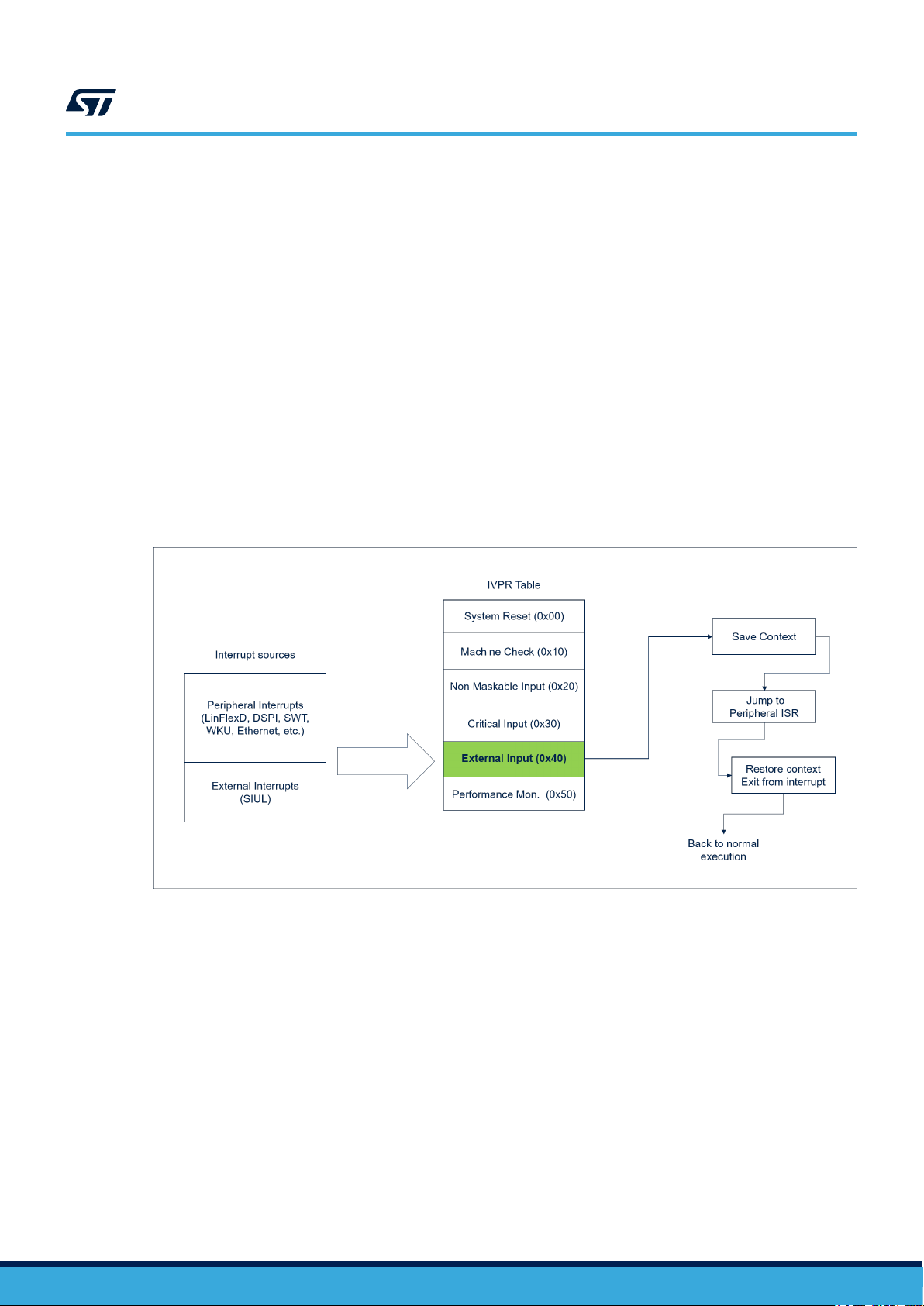
In the software Vector Mode all peripheral interrupts generate the External Interrupt Exception as described in
Figure 3.
AN5549
Interrupts
Figure 3. Software Vector Mode Interrupts
AN5549 - Rev 1
page 4/15
Page 5
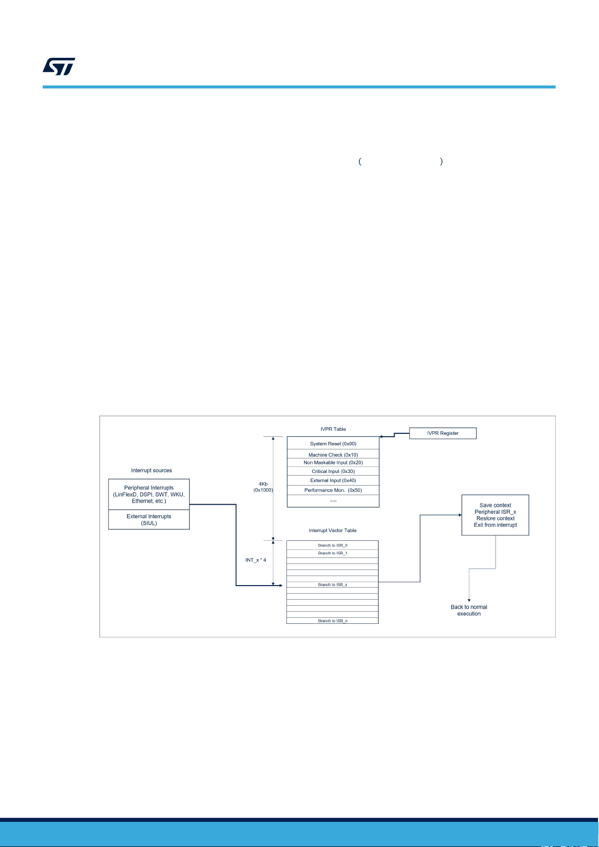
1.2.3 Hardware Vector Mode
In the hardware Vector Mode, as soon as a peripheral interrupt is raised, the control jumps to execute the code
located at a specific address in the Interrupt Vector table which can be calculated as follows:
Execution address = Vector base + 0x1000 + Interrupt number × 4
Where:
• Vector Base is the content of the IVPR register
• 0x1000 is a 4 Kb fixed offset
• Interrupt Number is the interrupt number associated with the peripheral which has raised the interrupt
After taking an interrupt, the execution will continue executing code at Execution Address where there will be an
unconditional jump to the peripheral ISR.
The peripheral ISR:
• Reserves appropriate space on the stack to save the Core context (PC, MSR, SRR0, SRR1, CR, LR, CTR,
XER, GPR0, …, GPR12)
• Enables global interrupts (to allow nested interrupts)
• Manages the peripheral interrupt(s)
• Disables global interrupts
• Acknowledges the interrupt on the interrupt controller (INTC)
• Restores the context
• Returns from interrupt (to normal execution)
The hardware Vector Mode is described in Figure 4.
AN5549
Interrupts
(1)
Figure 4. Hardware Vector Mode Interrupts
1.2.4 Software Vector Mode vs. hardware Vector Mode
In the software Vector Mode all peripherals and external interrupts are routed to a single exception line (at offset
0x40, External Input) which, after reading the interrupt source ISR address from INTC IACKR register, jumps to
this handler. The code handling the External Input exception is also responsible for saving and restoring the
microcontroller context. In other words, there is only one place for all peripheral and external interrupts where to
save/restore the microcontroller context saving code space. On the other side to take an interrupt there is an extra
jump: first read the INTC in order to understand where is located the peripheral ISR, then do the jump to the ISR.
In the hardware Vector Mode, the jump to the peripheral ISR is done just after taking the interrupt (as first action)
then the ISR saves the context and manages the peripheral interrupt. Compared to the software Vector Mode
there is a jump less. The disadvantage is, there is an increase in code size: each interrupt service routine (ISR)
must save/restore the microcontroller context before managing the handler.
AN5549 - Rev 1
page 5/15
Page 6
2 Source code example
This section describes, using source code snippets, how to initialize, configure and manage Software and
Hardware Vector modes.
The source code in the following section refers to the Core_2 initialization only.
For multi-core devices duplicate the following source code for each available core. The source code, at the time of
writing, is inspired to the software provided by SPC5Studio tool available at www.st.com/spc5studio.
2.1 Software Vector Mode
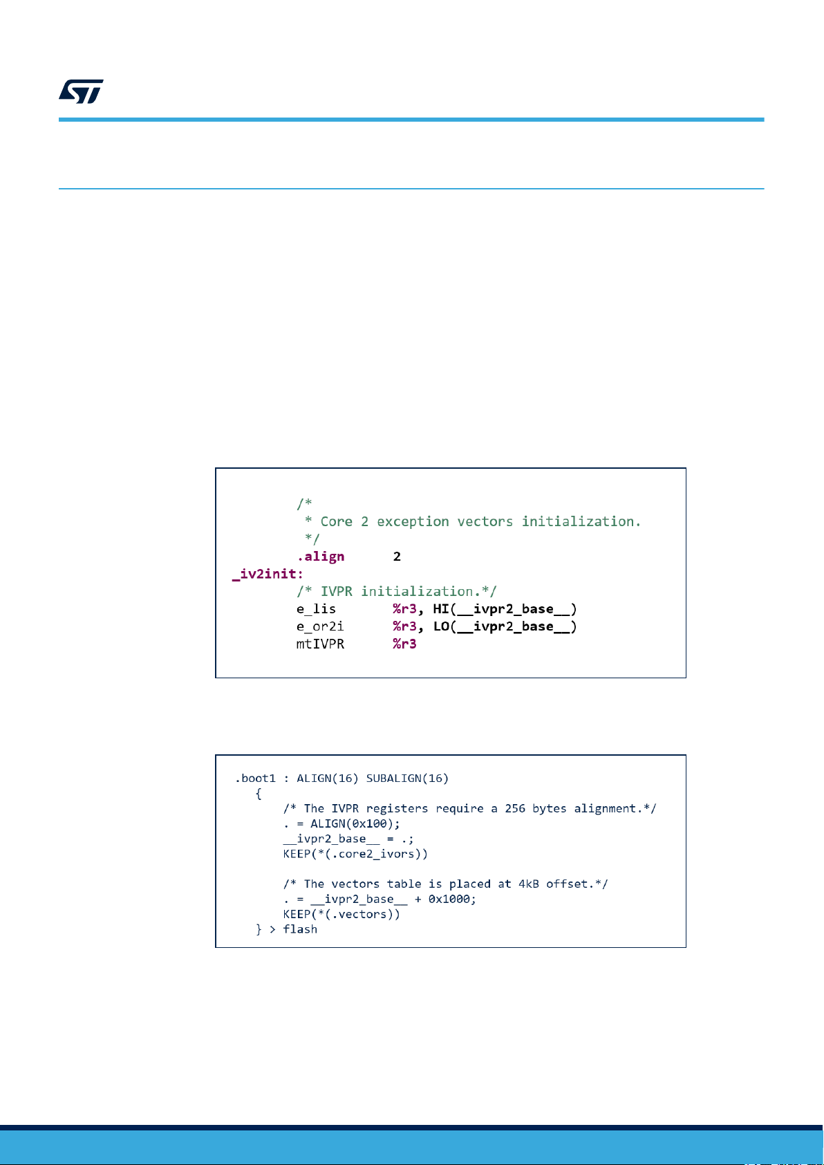
2.1.1 IVPR Initialization
At first stage the initialization of the IVPR register with the base address of the IVPR Table is needed. IVPR
initialization should be done by the boot code just after the initialization of the RAM.
This assembly code shows how to initialize the IVPR register.
AN5549
Source code example
Figure 5. IVPR initialization
The
__ivpr2_base__ variable is defined in the linker script file as the follows:
Figure 6. IVPR base variable initialization in linker script file
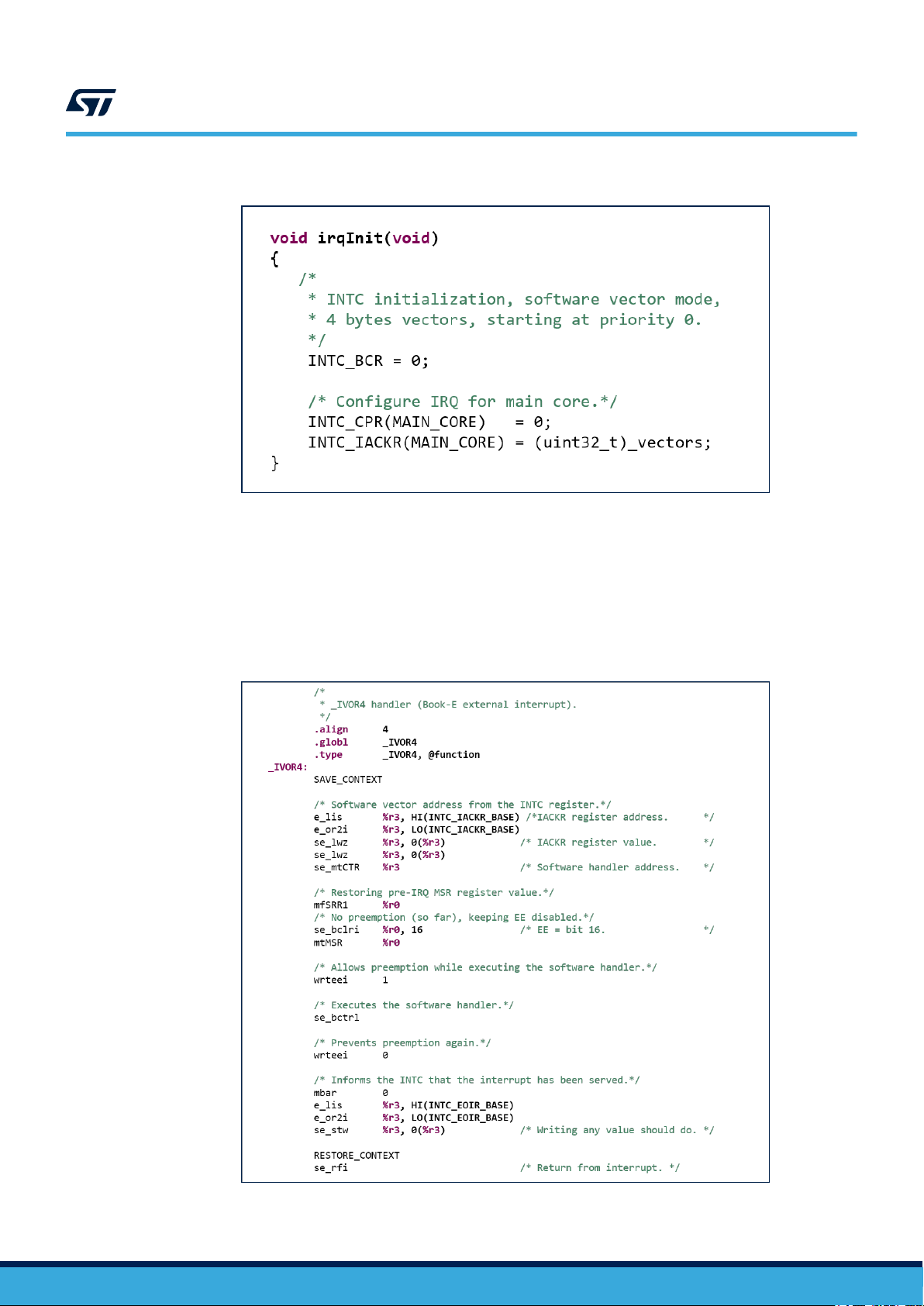
Finally, the initialization of the INTC:
AN5549 - Rev 1
page 6/15
Page 7
2.1.2 Interrupt Vector Table
In the software Vector Mode each entry in the interrupt Vector Table is 4 bytes wide and contains the address of
the Interrupt Service Routine (ISR) for each specific entry in the table.
For example, at entry 0 (zero) there is the ISR function to handle interrupt number 0 (zero).
AN5549
Software Vector Mode
Figure 7. INTC Initialization
2.1.3 External Input Exception (offset 0x40) handler
The External Input Exception (offset 0x40) handler should be implemented as follows:
Figure 8. External Input Exception Handler
AN5549 - Rev 1
page 7/15
Page 8

Finally SAVE_CONTEXT and RESTORE_CONTEXT macros:
Figure 9. Save and Restore Context macros
AN5549
Software Vector Mode
AN5549 - Rev 1
page 8/15
Page 9

2.2 Hardware Vector Mode
2.2.1 IVPR Initialization
In the hardware Vector Mode, IVPR initialization follows the same initialization as the software Vector Mode
except for the linker script initialization and INTC initialization.
The __ivpr2_base__ variable is defined in the linker script file as explained and the interrupt vector table should
be placed at 4Kb offset from the __ivpr2_base__ (the content of the IVPR register).
Figure 10. IVPR base variable initialization in linker script file
AN5549
Hardware Vector Mode
INTC initialization should be done as follows:
2.2.2 Interrupt Vector Table
In the hardware Vector Mode each entry in the interrupt vector table is 4 bytes wide and contains the instruction to
jump to the Interrupt Service Routine (ISR) for each specific entry in the table.
For example, at entry 0 (zero) there is the branch to the ISR function to handle interrupt number 0 (zero).
Figure 11. INTC Initialization
AN5549 - Rev 1
page 9/15
Page 10

2.2.3 ISR handler
The ISRx (for interrupt number ‘x’ and located at position ‘x’ in interrupt vector table) should be implemented as
follows:
AN5549
Hardware Vector Mode
Figure 12. ISRx handler
Save and restore context macros are implemented as Software Vector Mode.
ISRx_handler is the ‘C’ implementation of the interrupt handler serving the interrupt number ‘x’.
AN5549 - Rev 1
page 10/15
Page 11

Revision history
AN5549
Table 2. Document revision history
Date Version Changes
28-Sep-2020 1 Initial release.
AN5549 - Rev 1
page 11/15
Page 12

AN5549
Contents
Contents
1 Interrupts and Exceptions .........................................................2
1.1 Exceptions ....................................................................2
1.1.1 Interrupt Vector Prefix Registers (IVPR) .......................................2
1.2 Interrupts .....................................................................3
1.2.1 Interrupt Controller (INTC)..................................................3
1.2.2 Software Vector Mode.....................................................4
1.2.3 Hardware Vector Mode ....................................................5
1.2.4 Software Vector Mode vs. hardware Vector Mode................................5
2 Source code example..............................................................6
2.1 Software Vector Mode ..........................................................6
2.1.1 IVPR Initialization ........................................................6
2.1.2 Interrupt Vector Table .....................................................7
2.1.3 External Input Exception (offset 0x40) handler ..................................7
2.2 Hardware Vector Mode..........................................................9
2.2.1 IVPR Initialization ........................................................9
2.2.2 Interrupt Vector Table .....................................................9
2.2.3 ISR handler ............................................................10
Revision history .......................................................................11
AN5549 - Rev 1
page 12/15
Page 13

AN5549
List of tables
List of tables
Table 1. Common Interrupt types ...............................................................2
Table 2. Document revision history ............................................................. 11
AN5549 - Rev 1
page 13/15
Page 14

AN5549
List of figures
List of figures
Figure 1. Interrupt Vector Prefix Register .........................................................2
Figure 2. Process of taking an exception .........................................................3
Figure 3. Software Vector Mode Interrupts........................................................4
Figure 4. Hardware Vector Mode Interrupts ....................................................... 5
Figure 5. IVPR initialization ..................................................................6
Figure 6. IVPR base variable initialization in linker script file............................................6
Figure 7. INTC Initialization ..................................................................7
Figure 8. External Input Exception Handler ....................................................... 7
Figure 9. Save and Restore Context macros ......................................................8
Figure 10. IVPR base variable initialization in linker script file............................................9
Figure 11. INTC Initialization ..................................................................9
Figure 12. ISRx handler .................................................................... 10
AN5549 - Rev 1
page 14/15
Page 15

AN5549
IMPORTANT NOTICE – PLEASE READ CAREFULLY
STMicroelectronics NV and its subsidiaries (“ST”) reserve the right to make changes, corrections, enhancements, modifications, and improvements to ST
products and/or to this document at any time without notice. Purchasers should obtain the latest relevant information on ST products before placing orders. ST
products are sold pursuant to ST’s terms and conditions of sale in place at the time of order acknowledgement.
Purchasers are solely responsible for the choice, selection, and use of ST products and ST assumes no liability for application assistance or the design of
Purchasers’ products.
No license, express or implied, to any intellectual property right is granted by ST herein.
Resale of ST products with provisions different from the information set forth herein shall void any warranty granted by ST for such product.
ST and the ST logo are trademarks of ST. For additional information about ST trademarks, please refer to www.st.com/trademarks. All other product or service
names are the property of their respective owners.
Information in this document supersedes and replaces information previously supplied in any prior versions of this document.
© 2020 STMicroelectronics – All rights reserved
AN5549 - Rev 1
page 15/15
 Loading...