


ADJ
v+
v-
21
3
LM134
LM234 - LM334
THREE TERMINAL ADJUSTABLE CURRENT SOURCES
■ OPERATES FROM 1V TO 40V
■ 0.02%/V CURRENT REGULATION
■ PROGRAMMABLE FROM 1µA TO 10mA
■ ±3% INITIAL ACCURACY
DESCRIPTION
The LM134/LM234/LM334 are 3-terminal adjustable current sources characterized by:
❑ an operating current range of 10000: 1
❑ an excellent current regulation
❑ a wide dynamic voltage range of 1V t 10V
The current is determined by an external resistor
without requiring other external components.
Reverse voltages of up to 20V will only draw a current of several microamperes. This enables the
circuit to operate as a rectifier and as a so urce of
current in a.c. applications.
For the LM134/LM234/LM33 4, the voltage on the
control pin is 64m V at +25°C and is direct ly proportional to the absolute temperature (°K). The
simplest external resistor conn ection ge nerates a
current with ≈ 0.33%/°C temperature dependence.
Zero drift can be obtained by adding an additional
resistor and a diode to the external circuit.
Z
TO92
(Plastic Package)
D
SO8
(Plastic Micropacka ge)
ORDER CODE
Part Number
LM134 -55°C, +125°C
LM234 -25°C, +100°C
LM334 0°C, +70°C
Z = TO92 Plastic package - also available in Bulk (Z), Tape & Reel (ZT)
and Ammo Pack (AP)
D = Small Outline Package (SO) - also available in Tape & Reel (DT)
Temperature
Range
Package
ZD
••
••
••
PIN CONNECTIONS (top view)
TO92
(Top view)
May 2003
SO8
(Top view)
NC NCV-NC
8765
1234
ADJNCNC
V+
1/11
LM134 - LM234 - LM334
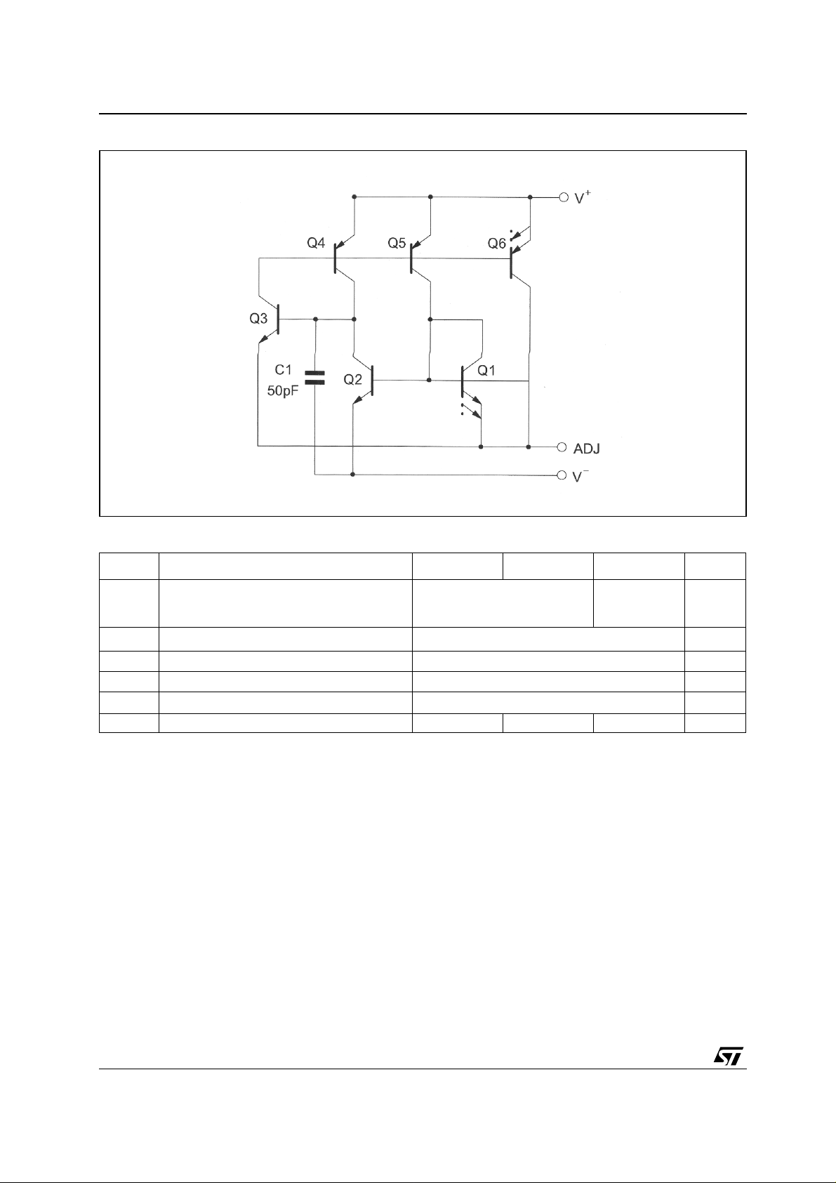
SCHEMATIC DIAGRAM
ABSOLUTE MAXIMUM RATINGS
Symbol Parameter LM134 LM234 LM334 Unit
Voltage V+ to V-
Forward
Reverse
-
V
I
P
T
ADJ Pin to V- Voltage
ADJ
Set Current 10 mA
SET
Power Dissipation 400 mW
tot
Storage Temperature Range -65 to +150 °C
Stg
Toper Operating Free-air Temperature Range -55 to +125 -25 to +100 0 to +70 °C
40
20
30
20
5V
V
2/11
LM134 - LM234 - LM334
ELECTRICAL CHARACTERISTICS
Tj = +25°C with pulse testing so that junction temperature does not change during testing (unless
otherwise specified)
Parameter
Set Current Error (V
10µA ≤ I
1mA ≤ I
2µA ≤ I
Ratio of Set Current to V
10µA ≤ I
1mA ≤ I
2µA ≤ I
+
= +2.5V) -1)
≤ 1mA
SET
≤ 5mA
SET
≤ 10µA
SET
≤ 1mA
SET
≤ 5mA
SET
≤ 10µA
SET
Current
-
Minimum Operating Voltage
2µA ≤ I
100µA ≤ I
1mA ≤ I
≤ 100µA
SET
SET
≤ 5mA
SET
≤ 1mA
Average Change in Set Current with Input Voltage
2µA ≤ I
1mA ≤ I
Temperature Dependence of set current -
25µA ≤ I
≤ 1mA
SET
+1.5V ≤ V
+5V ≤ V
≤ 5mA
SET
+1.5V ≤ V
+5V ≤ V
≤ 1mA
SET
≤ +5V
+
≤ +40V
+
≤ +5V
+
≤ +40V
+
2)
Effective Shunt Capacitance 15 15 pF
LM134 - LM234 LM334
Min. Typ. Max. Min. Typ. Max.
14 18
14
14
0.8
0.9
0.02
0.01
0.03
0.02
3
5
8
23 14 18
1
0.05
0.03
14
14
0.8
0.9
1
0.02
0.01
0.03
0.02
6
8
12
26
0.1
0.05 % / V
0.96 T T 1.04 T 0.96 T T 1.04 T
Unit
%
V
1. Set current is the current flowing into the V+ pin. It is determined by the following formula Iset = 67.7mV/Rset (Tj = +25°C)
Set curren t e rror is expressed as a percent devi at i on from this am ount
2. Iset is directly propor tional to ab solute temperature (° K). Iset at any t em perature can be calculated from I set = Io (T/To) where Io is Iset
measured a t To (°K)
3/11
LM134 - LM234 - LM334
4/11
LM134 - LM234 - LM334
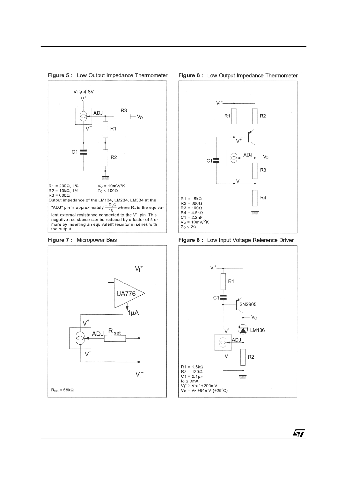
APPLICATION HINTS
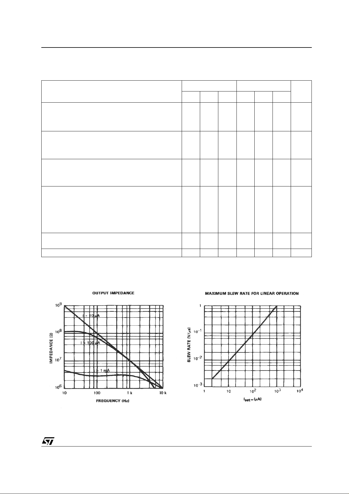
SLEW RATE
At slew rates above a threshold (see curve) the
LM134, LM234, LM334 can have a non-linear current characteristic. The slew rate at which this
takes place is directly proportional to Iset. At Iset =
10µA, dv/dt max. = 0.01V/µs ; at Iset = 1mA, dv/dt
max. = 1V/µs. Slew rates of more than 1V/µs do
not damage the circuit nor do they produce hi gh
currents.
THERMAL EFFE C T S
Internal heating can have a significant effect on
current regulation for an Iset above 100µA. For example, each increase of 1V in the voltage across
the LM134 at Iset = 1mA will increase the junction
temperature by ≈ 0.4°C (in still air). The output
current (Iset) has a temperature coefficient of
about 0.33%/°C. Thus t he change in current due
to the increase in temperature will be (0.4) (0.33) =
0.132%. This is degradation of 10 : 1 in regulation
versus the true electrical effects. Thermal effe cts
should be taken into account when d.c. regulation
is critical and Iset is higher than 100µA.
SHUNT CAPACITANCE
In certain applications, the 15pF value for the
shunt capacitance should be reduced :
❑ because of loading problems,
❑ because of limitation of output imped ance
of the current source in a.c. applications.
This reduction of capacitance can be easily
carried out by adding a FET as indicated in
the typical applications.
The value of this c apacitance can b e reduced by
at least 3pF and regulation can be improved by an
order of magnitude without any modifications of
the d.c. characteristics (except for the minimum input voltage).
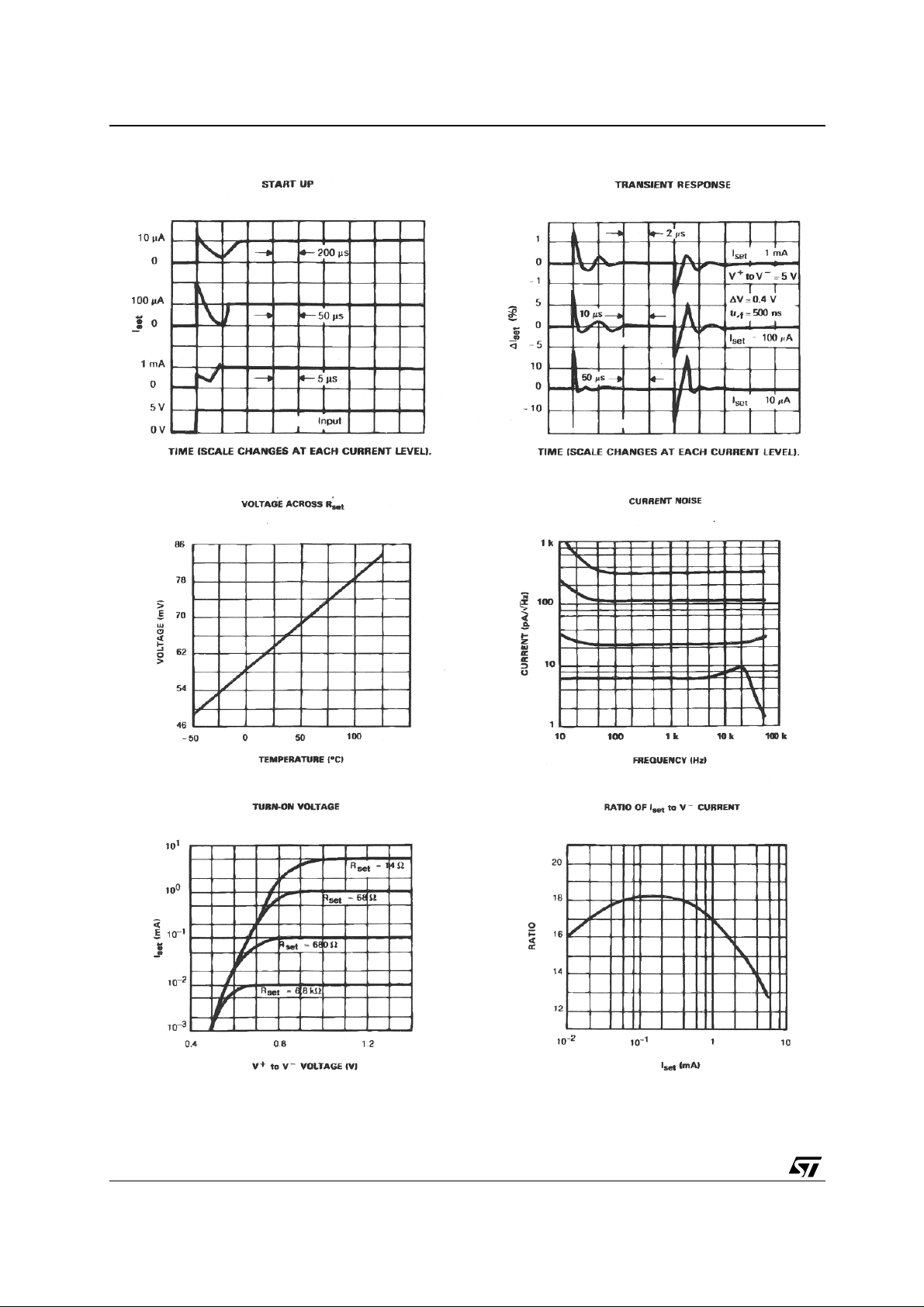
NOISE
The current noise produced by LM134, LM234,
LM334 is about 4 tim es that of a transistor. If the
LM134, LM234, LM334 is used as an active lo ad
for a transistor amplifier, the noise at the input will
increase by about 12dB. In most cases this is acceptable, and a single amplifier can be built with a
voltage gain higher than 2000.
LEAD RESISTANCE
The sense voltage which determines the current
of the LM134, LM234, LM334 is less than 100mV.
At this level, the thermocouple effects and the
connection resistance should be reduced by locating the current setting resistor close to the device.
Do not use sockets for the ICs. A contact resistance of 0.7Ω is sufficient to decrease the output
current by 1% at the 1mA level.
SENSING TEMPERAT URE
The LM134, LM234 , LM334 are excellen t remote
controlled temperature s ensors because t heir operation as current sources preserves their accuracy even in the case of long connecting wires. T he
output current is directly proportional to the absolute temperature in Kelvin degrees according to
the following equation.
227µV/°K) (T
()
Iset =
----------------------------------------Rset
The calibration of the LM134, LM234, LM334 is
simplified by the fact that most of the initial accuracy is due to gain limitation (slope error) and not an
offset. Gain adjustment is a one point trim because the output of the device extrapolates to zero
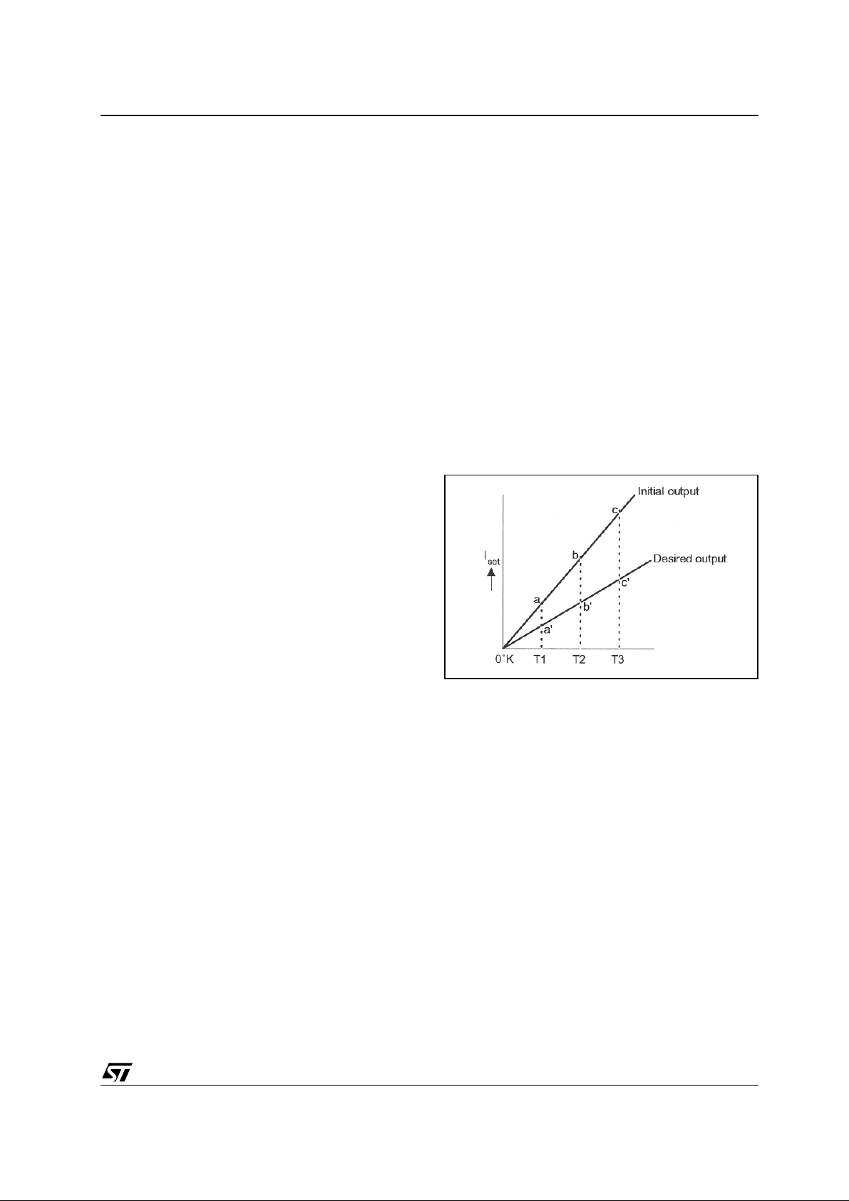
at 0°K.
This particularity of the LM134, LM234, LM334 is
illustrated in the above diagram. Line abc represents the sensor current before adjustment and
line a’b’c’ represents the desired output. A gain
adjustment provided at T2 will move the output
from b to b’ an d will correc t the slope at the sam e
time so that the output at T1 and T3 will be correct.
This gain adjustment can be carried out by means
of Rset or the load resistor used in the circuit. After
adjustment, the slope error should be less than
1%. A low temperature coefficient for Rset is nec essary to keep this accuracy. A 33ppm/°C temperature drif t of Rset w ill give an erro r of 1% on the
slope because the resistance follows the same
temperature variations as the LM134, LM234,
LM334. Three wires are required to isolate Rset
from the LM134, LM2 34, LM334. Since this solution is not recommended. Metal-film resistors with
a drift less than 20ppm/°C are now available.
Wirewound resistors can be use d w hen very high
stability is required.
5/11

LM134 - LM234 - LM334
6/11
LM134 - LM234 - LM334
7/11

LM134 - LM234 - LM334
8/11

LM134 - LM234 - LM334
PACKAGE MECHANICAL DATA
SO-8 MECHANICAL DATA
DIM.
A 1.35 1.75 0.053 0.069
A1 0.10 0.25 0.04 0.010
A2 1.10 1.65 0.043 0.065
B 0.33 0.51 0.013 0.020
C 0.19 0.25 0.007 0.010
D 4.80 5.00 0.189 0.197
E 3.80 4.00 0.150 0.157
e 1.27 0.050
H 5.80 6.20 0.228 0.244
h 0.25 0.50 0.010 0.020
L 0.40 1.27 0.016 0.050
k ˚ (max.)
ddd 0.1 0.04
MIN. TYP MAX. MIN. TYP. MAX.
mm. inch
8
9/11
0016023/C

LM134 - LM234 - LM334
PACKAGE MECHANICAL DATA - TO92 TAPE AMMO PACK & TO92 TAPE & REEL
TO-92 MECHANICAL DATA
DIM.
AL 5.0 0.197
A 5.0 0.197
T 4.0 0.157
d 0.45 0.018
I1 2.5 0.098
P 11.7 12.7 13.7 0.461 0.500 0.539
PO 12.4 12.7 13 0.488 0.500 0.512
P2 5.95 6.35 6.75 0.234 0.250 0.266
F1/F2 2.4 2.5 2.8 0.094 0.098 0.110
h -1 0 1 -0.039 0 0.039
D
P -1 0 1 -0.039 0 0.039
D
W 17.5 18.0 19.0 0.689 0.709 0.748
W0 5.7 6 6.3 0.224 0.236 0.248
W1 8.5 9 9.75 0.335 0.354 0.384
W2 0.5 0.020
H 20 0.787
H0 15.5 16 16.5 0.610 0.630 0.650
H1 25 0.984
DO 3.8 4.0 4.2 0.150 0.157 0.165
L1 11 0.433
MIN. TYP MAX. MI N. TYP. MAX.
mm. inches
Packing information are available at: http://www.st.com/stonline/prodpres/packages/stdlin.htm
10/11
LM134 - LM234 - LM334
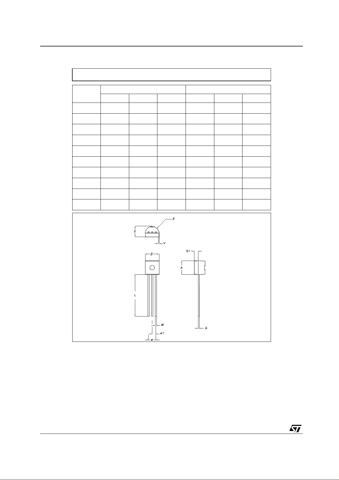
PACKAGE MECHANICAL DATA - TO92 BULK
TO-92 MECHANICA DATA
DIM.
A 4.32 4.95 170.1 194.9
b 0.36 0.51 14.2 20.1
D 4.45 4.95 175.2 194.9
E 3.30 3.94 129.9 155.1
e 2.41 2.67 94.9 105.1
e1 1.14 1.40 44.9 55.1
L 12.7 15.49 500.0 609.8
R 2.16 2.41 85.0 94.9
S1 0.92 1.52 36.2 59.8
W 0.41 0.56 16.1 22.0
MIN. TYP MAX. MIN. TYP. MAX.
mm. mils
0102782/C
Packing information are available at: http://www.st.com/stonline/prodpres/packages/stdlin.htm
Information furnished is bel ieved to be accurate and reliable. However, STMicroe lectronics assumes no responsibility for the
consequences of use of such information nor for any infringement of patents or other rights of third parties which may result from
its use. No li cen se is granted by implication or otherwise un der any patent or pate nt ri ghts of STMicroelectronics. Spec ifi cations
mentioned in this publication a re subject to change without notice. This publicat ion supersedes and replaces all information
previously supplied. STMicroelectronics products are not authorized for use as critical components in life support devices or
systems without express written approval of STMicroelectronics.
Australi a - Brazil - Chi na - Finlan d - F rance - Germ any - Hong Kong - India - It al y - Japan - Malaysia - Ma l ta - Morocco
11/11
The ST logo is a registered trademark of STMicroelectronics
© 2003 STMicroelectronics - All Rights Reserved
STMicroelectronics GROUP OF COMPANIES
Singap ore - Spain - Sweden - Swi t zerland - United Kingdom
http://www.st.com
 Loading...