

Page 1

Application note
L9963 14 Cells BMC IC Evaluation Board Quick Guide
Introduction
This document is intended as quick guide to help the user in the startup phase of EVAL-L9963-MCU combining and
summarizing the information contained in EVAL-L9963-MCU and STSW-L9963 user manuals.
AN5560
AN5560 - Rev 2 - November 2020
For further information contact your local STMicroelectronics sales office.
www.st.com
Page 2
AN5560
What you need
1 What you need
• EVAL-L9963-MCU
• USB cable
• Power supply (at least 3 output 0 – 30 V (if possible 60V):
– 1 output to power L9963 (0:60 V)
– 1 output to simulate Cells common mode voltage (0:60 V)
– 1 output to simulate Cell voltage (0:5 V)
• L9963 evaluation GUI STSW-L9963
• NI Labview-runtime 2014
• NI VISA-RUNTIME
Note: Before using the UART/USB bridge FT2232H, the Virtual Com Port (VCP D2XX) driver needs to be installed. It
can be downloaded by the FTDI Chip website.
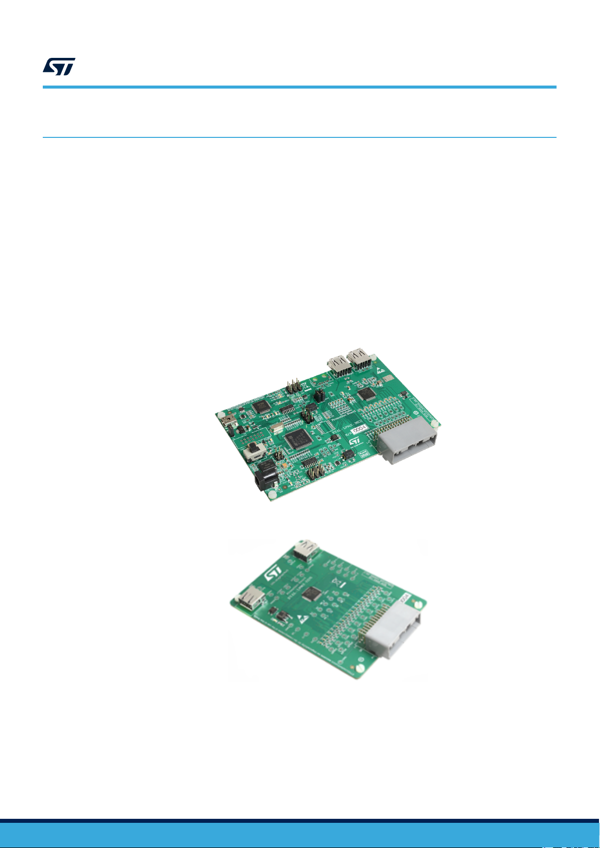
Figure 1. EVAL-L9963-MCU board
Figure 2. EVAL-L9963-NDS board
AN5560 - Rev 2
page 2/25
Page 3
2 Board description
AN5560
Board description
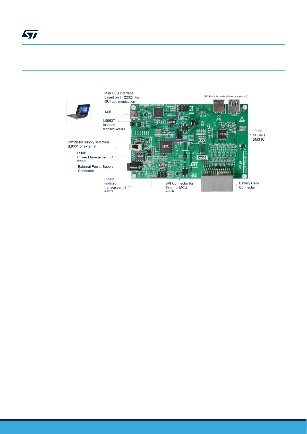
Figure 3. Main components and connectors
Note: 1. EVAL-L9963-MCU can be considered the only stage or the first stage of several stages. The port is the
isolated vertical interface to the next stage (EVAL-L9963-NDS);
2. A second L9963T (optional) may be needed to create a direct loop with the last stage (dual ring access);
3. MCU can be supplied either by USB or by L9001 (PMIC);
4. On board MCU can be bypassed in case a different MCU is needed for the user trials; these pins allow
an SPI connection with an external MCU (upon a specific board configuration). Anyway a specific board
derivative of EVAL-L9963-MCU has been designed for this purpose (same form factor/layout with MCU not
mounted: EVAL- L9963).
AN5560 - Rev 2
page 3/25
Page 4
3 Block diagram
AN5560
Block diagram
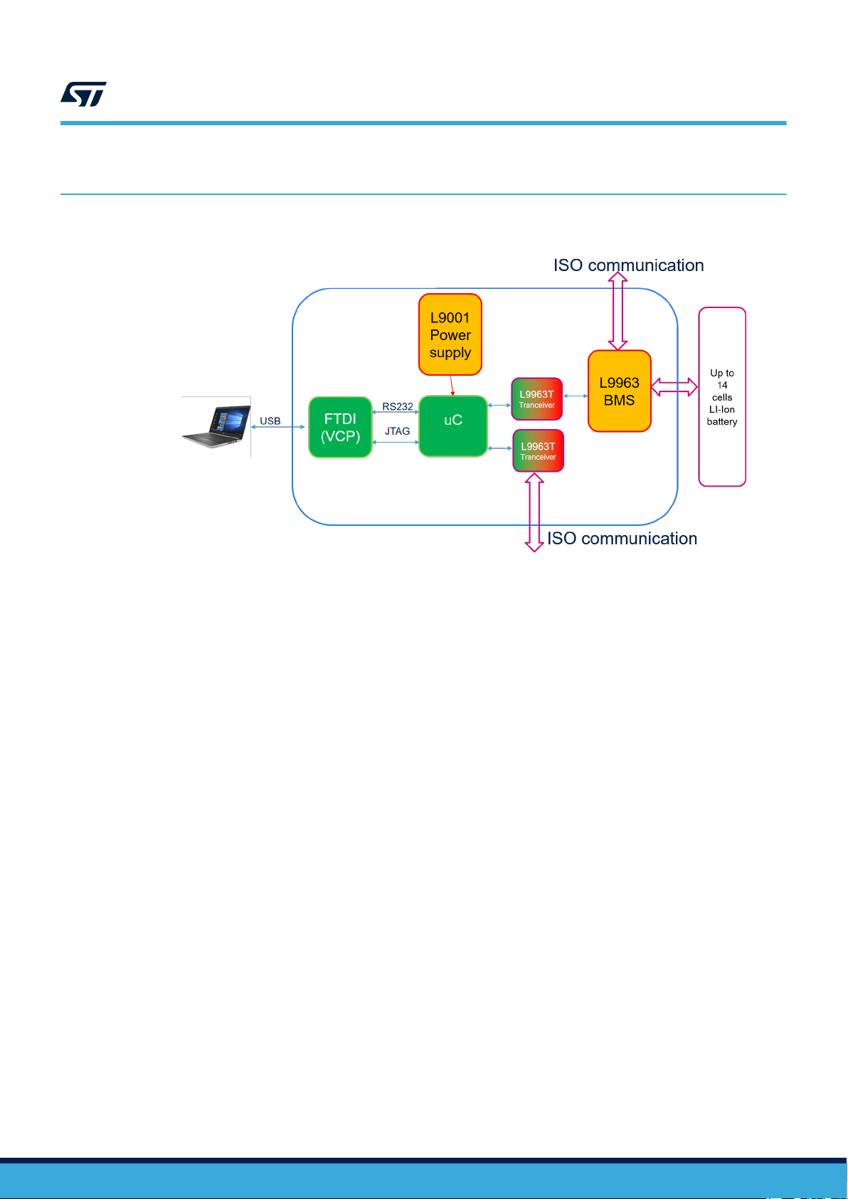
Figure 4. EVAL-L9963-MCU block diagram
AN5560 - Rev 2
page 4/25
Page 5
4 Microcontroller Power supply
Figure 5. Microcontroller Power supply
AN5560
Microcontroller Power supply
AN5560 - Rev 2
page 5/25
Page 6
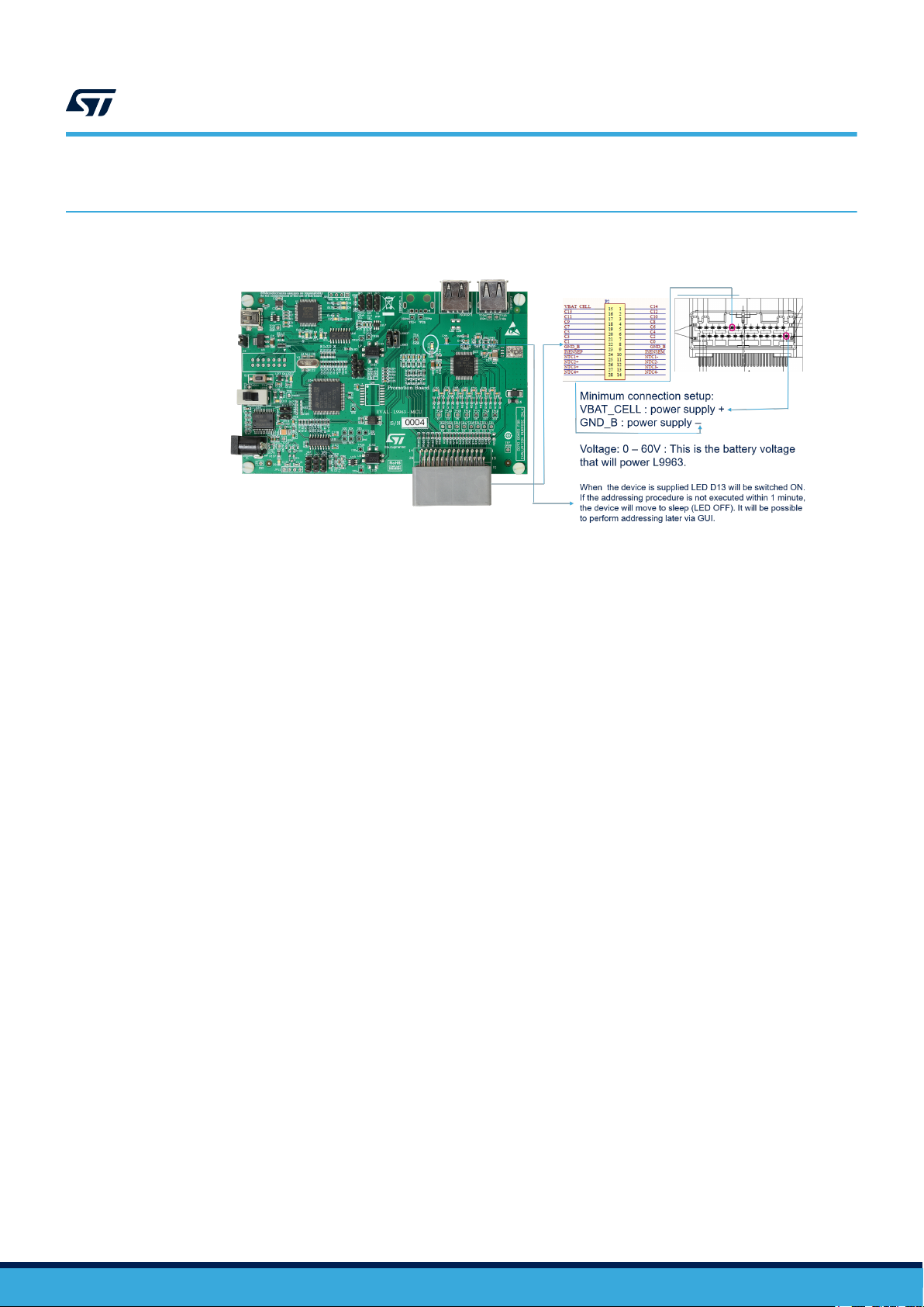
L9963 external connection and power supply
5 L9963 external connection and power supply
Figure 6. L9963 external connection and power supply
AN5560
AN5560 - Rev 2
page 6/25
Page 7
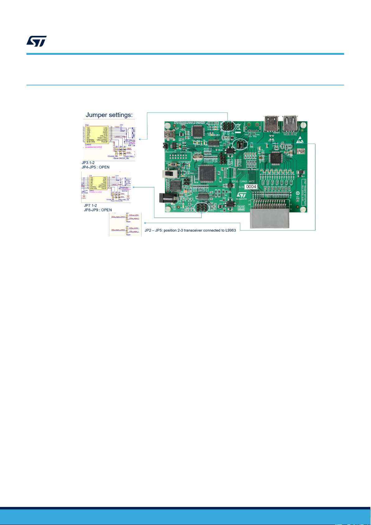
6 Transceiver settings
AN5560
Transceiver settings
Figure 7. Transceiver settings
AN5560 - Rev 2
page 7/25
Page 8

7 Possible connection for battery simulation
Figure 8. Battery simulation 1
AN5560
Possible connection for battery simulation
Figure 9. Battery simulation 2
AN5560 - Rev 2
page 8/25
Page 9

8 Preliminary action to open the GUI
Install the following SW on your PC:
• NI Labview-runtime 2014
• NI VISA-RUNTIME
• FTDI driver
– Before using the UART/USB bridge FT2232H, the Virtual Com Port (VCP) driver needs to be installed.
It can be downloaded by the FTDI Chip website.
When all is installed reboot your PC and open STSW-L9963.exe
AN5560
Preliminary action to open the GUI
AN5560 - Rev 2
page 9/25
Page 10

9 USB to PC connection
AN5560
USB to PC connection
Figure 10. USB to PC connection
AN5560 - Rev 2
page 10/25
Page 11

10 Device Manager appearance
If FTDI Virtual COM PORT (VCP D2XX) driver has been correctly installed, you will find in Windows Device
manager a USB serial port under Ports (COM&LPT). Take note of the COM port number (i.e. COM13).
Figure 11. Windows Device Manger COM port number
AN5560
Device Manager appearance
AN5560 - Rev 2
page 11/25
Page 12

11 GUI usage and setup
11.1 Connection
Steps:
1. Select COM port according to your device manager. The COM led will become green;
2. Press on “get firmware version” button to check the communication with uC and the firmware version. The
version should be 1.5;
3. In the “ID assignment” text box write 1 because you are using 1 L9963 then press “Configure IDs Button”,
ACK LED will become green. If D13 LED on the board was switched OFF it will be switched ON and will not
switch OFF anymore.
AN5560
GUI usage and setup
Figure 12. GUI connection
AN5560 - Rev 2
page 12/25
Page 13

11.2 Threshold configuration
Steps:
1. Select Cell overvoltage and undervoltage. i.e. UV 2.8 V and OV 4.250 V;
2. The VCELL_THRESH_UV_OV register will be automatically updated;
3. Select Dev ID 1;
4. Select Write;
5. Press on “Single write/read” button;
6. If communication with L9963 is ok the ACK LED will become green.
AN5560
Threshold configuration
Figure 13. Threshold configuration 1
AN5560 - Rev 2
page 13/25
Page 14
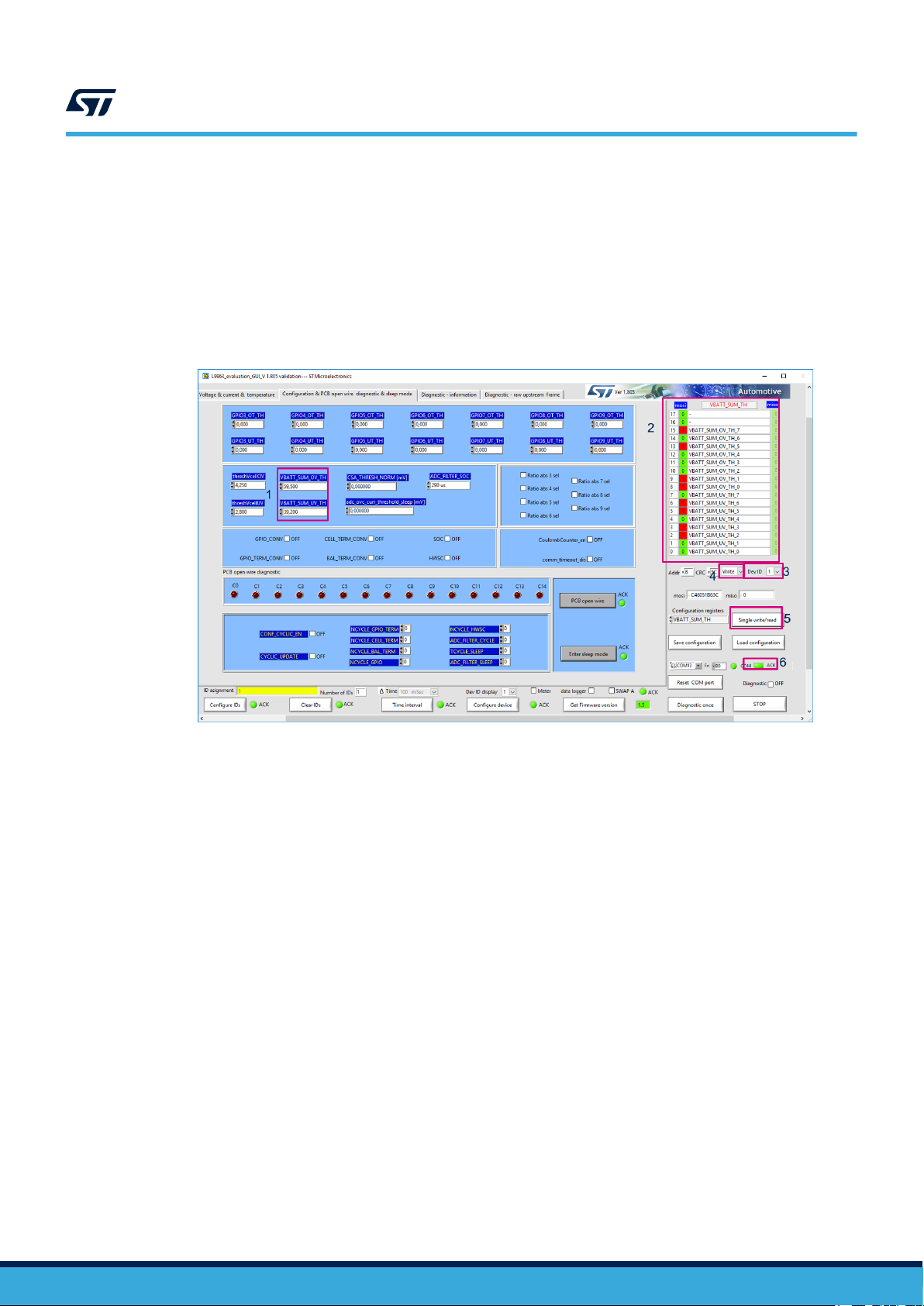
Steps:
1. Select Battery overvoltage and undervoltage. i.e. UV 39.2 V and OV 59.5 V;
2. The VBAT_SUM_TH register will be automatically updated;
3. Select Dev ID 1;
4. Select Write;
5. Press on “Single write/read” button;
6. If communication with L9963 is ok the ACK LED will become green.
Figure 14. Threshold configuration 2
AN5560
Threshold configuration
AN5560 - Rev 2
page 14/25
Page 15

11.3 Measure enabling
Steps:
1. Select cell voltage gauge with the EN check box. At least Cells 1, 2, 13, 14 must be selected;
2. The VCELLS_EN register will be automatically updated;
3. Select Dev ID 1;
4. Select Write;
5. Press on “Single write/read” button;
6. If communication with L9963 it’s ok the ACK LED will become green.
AN5560
Measure enabling
Figure 15. Measure enabling
AN5560 - Rev 2
page 15/25
Page 16

11.4 Measure starting
Steps:
1. Select time interval. i.e. 100 ms. This is the refresh rate of GUI measurement;
2. Press on “Time interval” button to apply setting. ACK LED will become green;
3. Check Diagnostic checkbox to start measurement.
AN5560
Measure starting
Figure 16. Measure starting
AN5560 - Rev 2
page 16/25
Page 17

11.5 Alternative measure setting
Figure 17. Alternative measure setting
AN5560
Alternative measure setting
AN5560 - Rev 2
page 17/25
Page 18
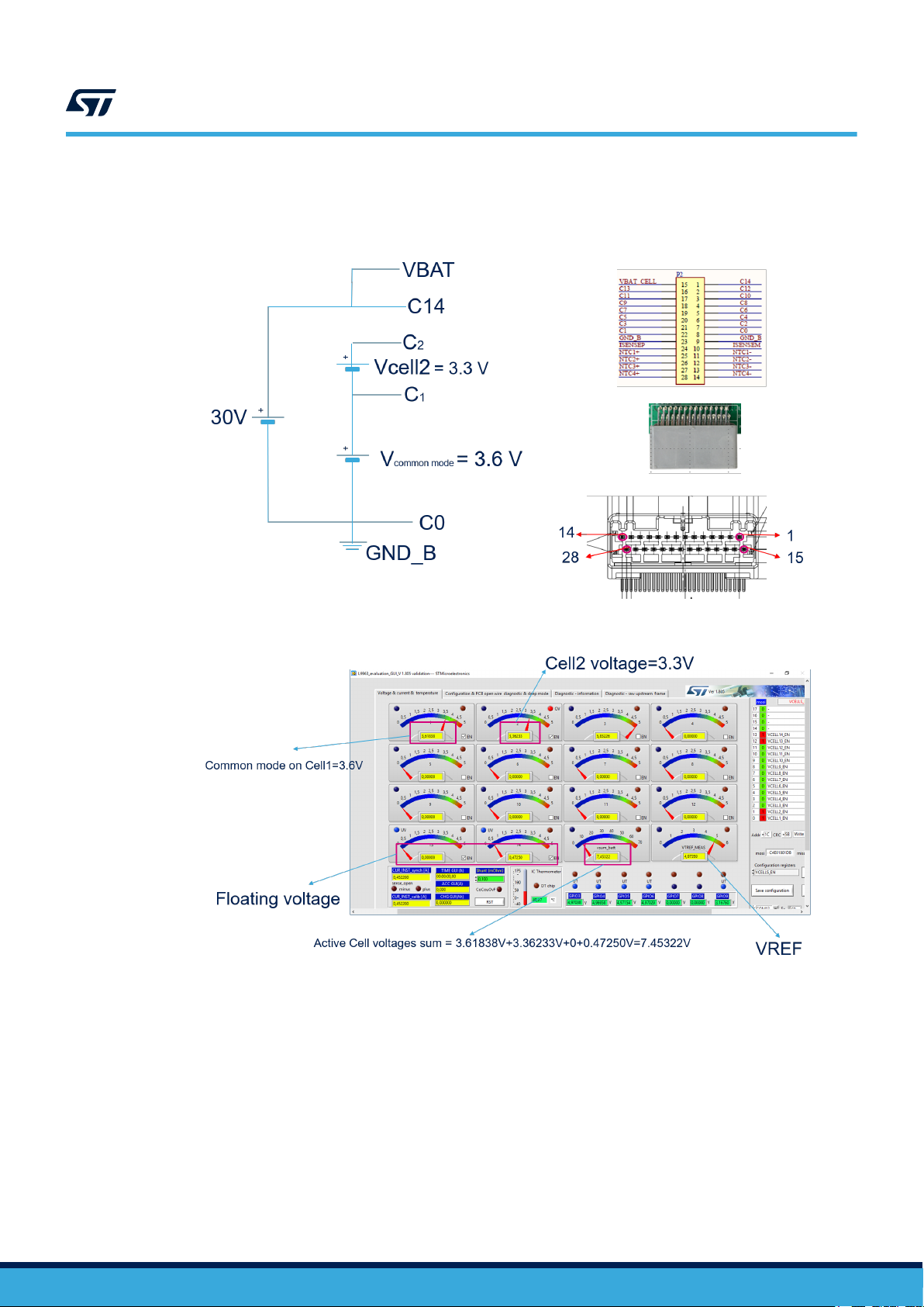
11.6 Measurements example
AN5560
Measurements example
Figure 18. Setup
Figure 19. Results
AN5560 - Rev 2
page 18/25
Page 19

11.7 Diagnostic
All the diagnostics are available in the Diagnostic-Information tab. They are updated at the same rate as
measurement.
AN5560
Diagnostic
Figure 20. Diagnostic
AN5560 - Rev 2
page 19/25
Page 20

Appendix A Reference documents
Table 1. Reference documents
Doc Name ID Title
UM2698 034111 EVAL-L9963-MCU Evaluation Board
UM2734 034356 L9963 evaluation graphical user interface
AN5560
Reference documents
AN5560 - Rev 2
page 20/25
Page 21

Revision history
AN5560
Table 2. Document revision history
Date Version Changes
15-Sep-2020 1 Initial release.
17-Nov-2020 2 Updated Title in cover page.
AN5560 - Rev 2
page 21/25
Page 22

AN5560
Contents
Contents
1 What you need ....................................................................2
2 Board description .................................................................3
3 Block diagram .....................................................................4
4 Microcontroller Power supply......................................................5
5 L9963 external connection and power supply ......................................6
6 Transceiver settings ...............................................................7
7 Possible connection for battery simulation.........................................8
8 Preliminary action to open the GUI .................................................9
9 USB to PC connection ............................................................10
10 Device Manager appearance ......................................................11
11 GUI usage and setup .............................................................12
11.1 Connection ...................................................................12
11.2 Threshold configuration ........................................................13
11.3 Measure enabling .............................................................15
11.4 Measure starting ..............................................................16
11.5 Alternative measure setting .....................................................17
11.6 Measurements example ........................................................18
11.7 Diagnostic ...................................................................19
Appendix A Reference documents....................................................20
Revision history .......................................................................21
AN5560 - Rev 2
page 22/25
Page 23

AN5560
List of tables
List of tables
Table 1. Reference documents ............................................................... 20
Table 2. Document revision history .............................................................21
AN5560 - Rev 2
page 23/25
Page 24

AN5560
List of figures
List of figures
Figure 1. EVAL-L9963-MCU board .............................................................2
Figure 2. EVAL-L9963-NDS board .............................................................2
Figure 3. Main components and connectors .......................................................3
Figure 4. EVAL-L9963-MCU block diagram .......................................................4
Figure 5. Microcontroller Power supply .......................................................... 5
Figure 6. L9963 external connection and power supply ...............................................6
Figure 7. Transceiver settings ................................................................ 7
Figure 8. Battery simulation 1.................................................................8
Figure 9. Battery simulation 2.................................................................8
Figure 10. USB to PC connection.............................................................. 10
Figure 11. Windows Device Manger COM port number ............................................... 11
Figure 12. GUI connection...................................................................12
Figure 13. Threshold configuration 1............................................................ 13
Figure 14. Threshold configuration 2............................................................ 14
Figure 15. Measure enabling ................................................................. 15
Figure 16. Measure starting.................................................................. 16
Figure 17. Alternative measure setting .......................................................... 17
Figure 18. Setup ......................................................................... 18
Figure 19. Results ........................................................................ 18
Figure 20. Diagnostic ...................................................................... 19
AN5560 - Rev 2
page 24/25
Page 25

AN5560
IMPORTANT NOTICE – PLEASE READ CAREFULLY
STMicroelectronics NV and its subsidiaries (“ST”) reserve the right to make changes, corrections, enhancements, modifications, and improvements to ST
products and/or to this document at any time without notice. Purchasers should obtain the latest relevant information on ST products before placing orders. ST
products are sold pursuant to ST’s terms and conditions of sale in place at the time of order acknowledgement.
Purchasers are solely responsible for the choice, selection, and use of ST products and ST assumes no liability for application assistance or the design of
Purchasers’ products.
No license, express or implied, to any intellectual property right is granted by ST herein.
Resale of ST products with provisions different from the information set forth herein shall void any warranty granted by ST for such product.
ST and the ST logo are trademarks of ST. For additional information about ST trademarks, please refer to www.st.com/trademarks. All other product or service
names are the property of their respective owners.
Information in this document supersedes and replaces information previously supplied in any prior versions of this document.
© 2020 STMicroelectronics – All rights reserved
AN5560 - Rev 2
page 25/25
 Loading...