

Page 1
EVAL-SCS003V1
Quick Start Guide
Customizing STUSB4761
using EVAL-SCS003V1 Dongle
Page 2
This document describes how to use an EVAL-SCS003V1 dongle in order to read
or update STUSB4761 NVM (Non Volatile Memory).
Introduction
2
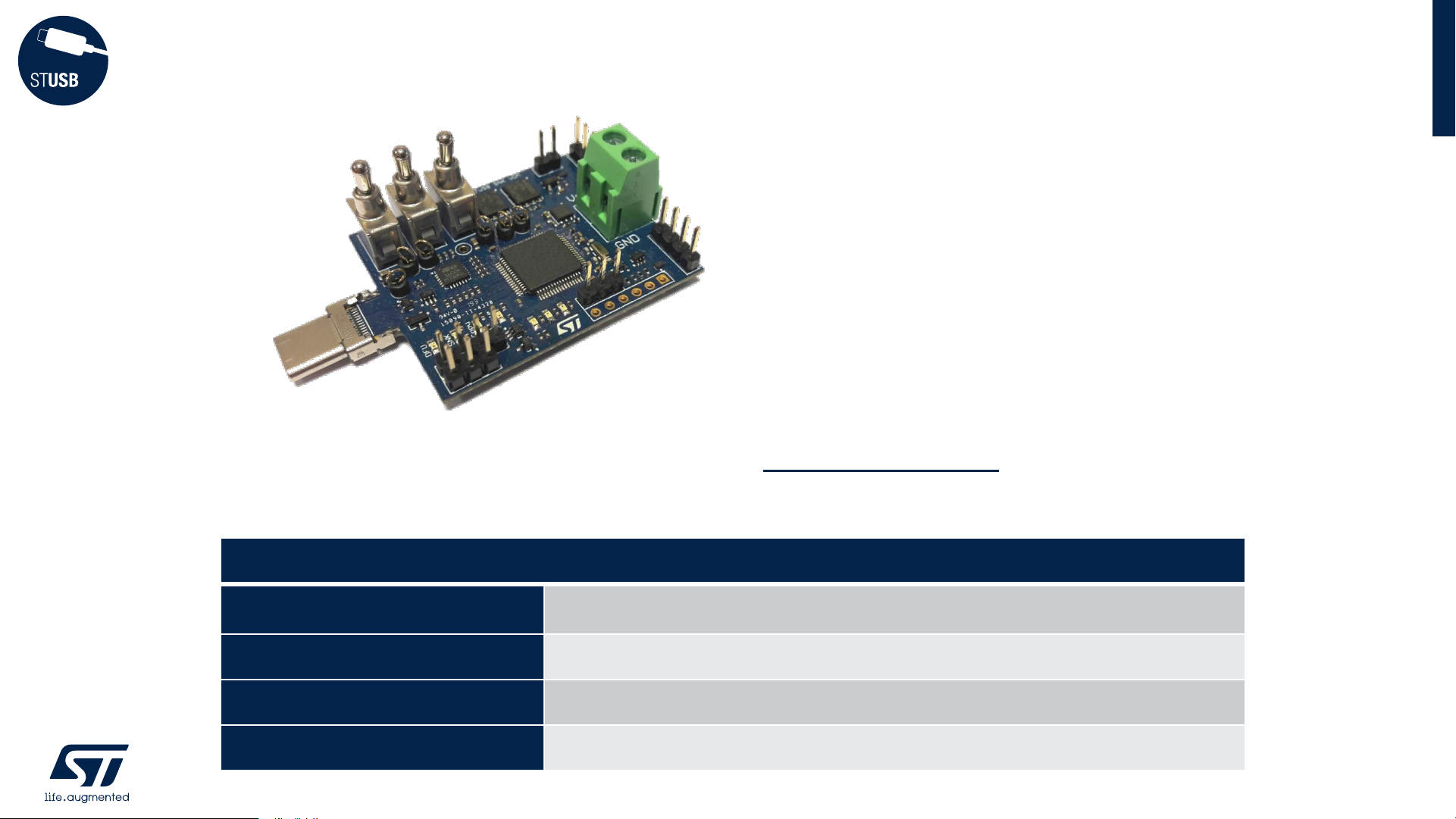
Related components
EVAL-SCS003V1
STUSB
utility dongle board
STSW-STUSB011
STUSB
utility dongle software package
STSW-STUSB005
STUSB4761
Graphical User Interface (GUI)
Operating System
Windows OS
Page 3

Summary
Quick Start
• EVAL-SCS03V1: switch configuration
• Pre-requisites - installation of STSW-STUSB011
• Pre-requisites - installation of DFU drivers
STUSB4761 customization using the GUI and the dongle
Reading STUSB4761 NVM content using the dongle and the GUI
Connecting to a SOURCE using SINK Mode
Updating EVAL-SCS003V1 dongle firmware using ‘DFU’ mode
Tricks
4
page
6
7
10
16
21
24
27
Page 4
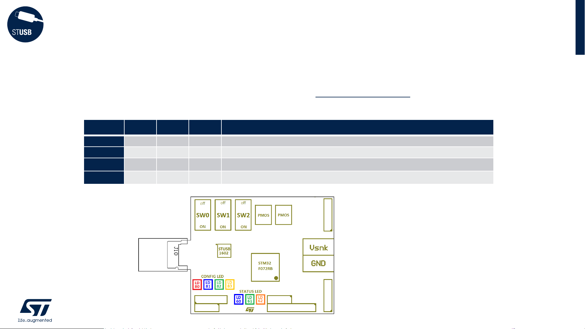
Depending on the switch configuration, the EVAL-SCS003V1 dongle can be
configured according to 4 modes:
Quick Start
4 modes
4
mode
SW0 SW1 SW2 function
DFU
ON
off off
This mode is used to configure and update the dongle firmware
COPY
off
ON ON
This mode configures the board as a STUSB4761 NVM reader
PASTE
off
ON
off
This mode configures the board as a STUSB4761 customization tool
SINK
off off off
This mode configures the board as a USB PD SINK device
Page 5

Dongle configuration and update is done using DFU (Device Firmware Update) mode.
This requires installation of the following package:
- STSW-STUSB011: follow steps and
Also, please ensure that DFU drivers are installed on your windows PC. If not, please
install also:
- STM32CubeProgrammer software: follow steps to
Quick Start
Pre-requisite (1/5)
5
1 2
3
9
Page 6
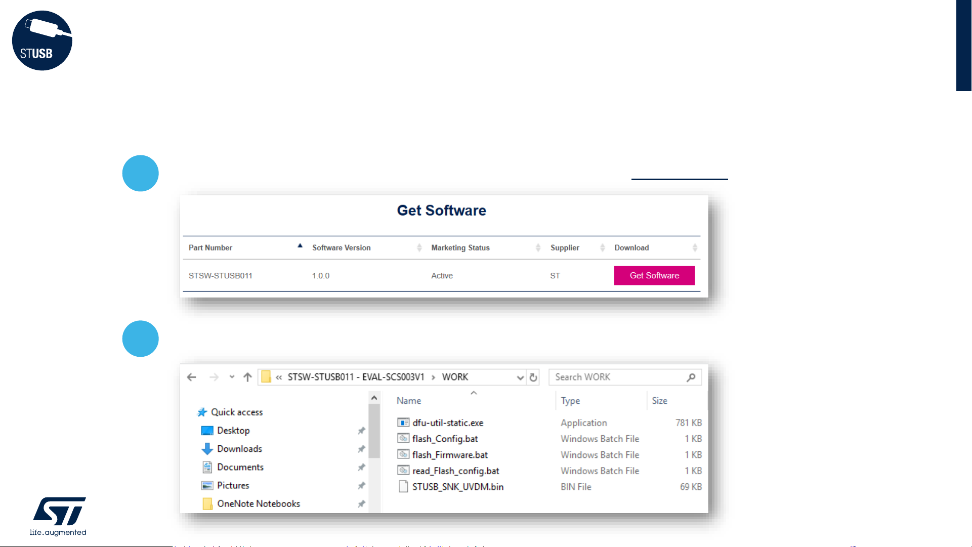
• Please search STSW-STUSB011 software package from www.st.com:
Quick Start
Pre-requisite (2/5)
6
1
Download and unzip in a working directory:
2
Page 7
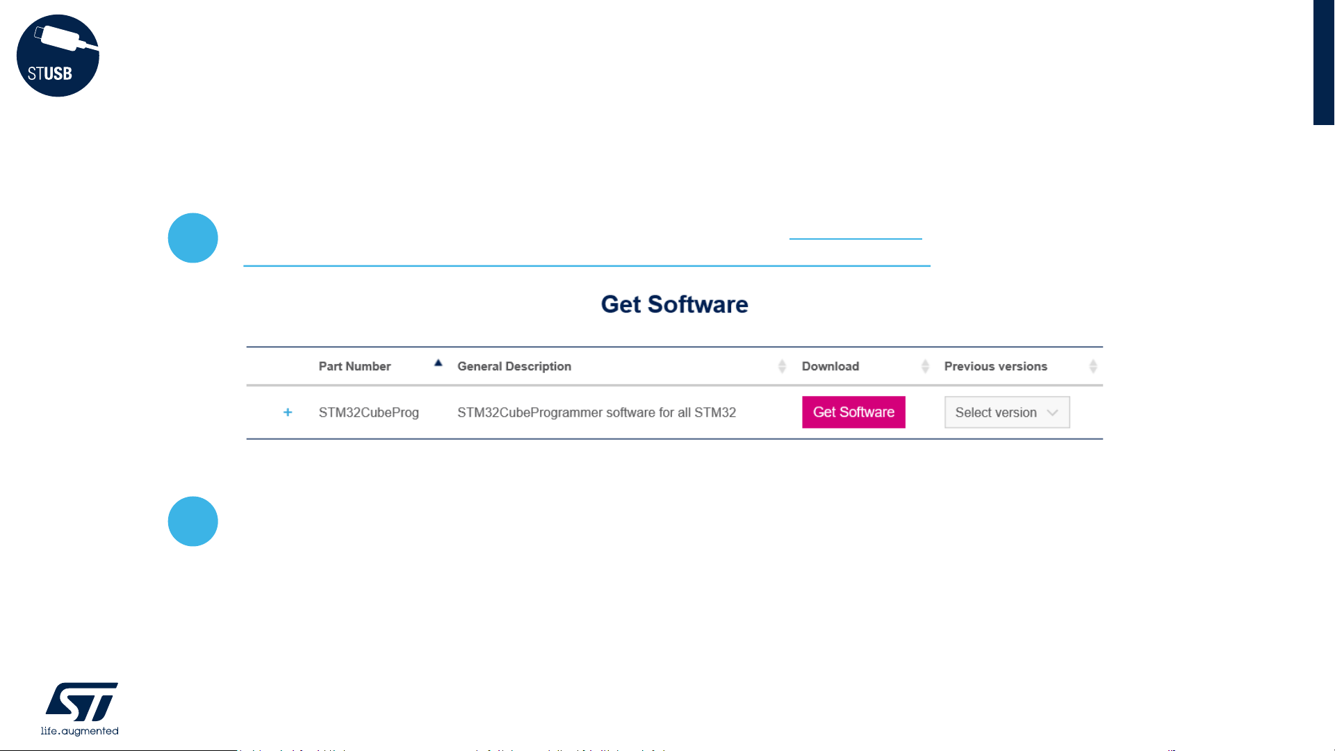
Search STM32CubeProg software package from www.st.com or click on:
https://www.st.com/en/development-tools/stm32cubeprog.html
Download, unzip and start the installation process by clicking on:
SetupSTM32CubeProgrammer-2.2.1.exe
Quick Start
Pre-requisite (3/5)
7
4
3
Page 8
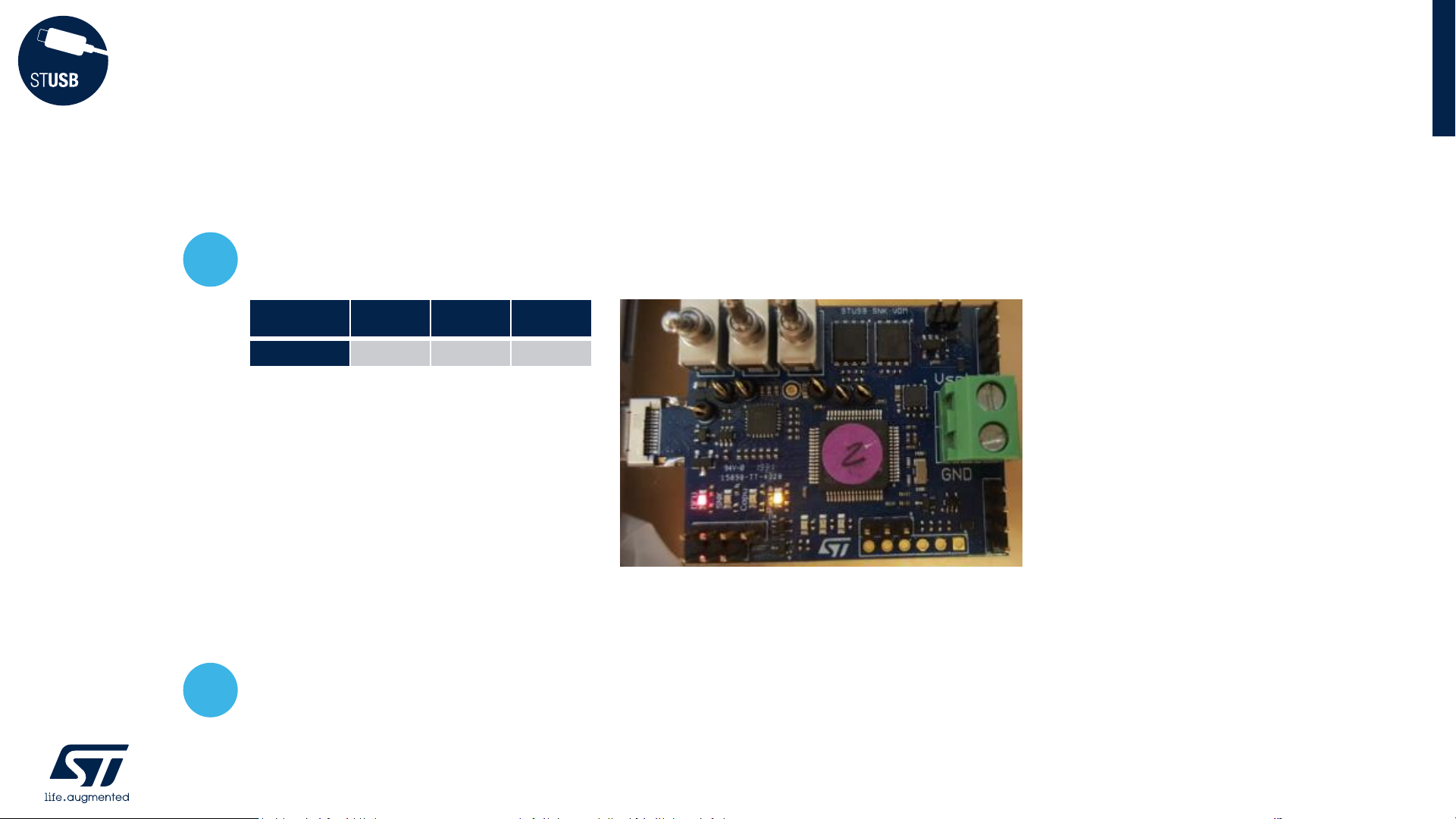
Plug EVAL-SCS003V1 board into USB-C port of the PC with below switch configuration:
NB: PC should find drivers by itself (installed by STM32CubeProgrammer)
Check that Red and Orange LEDs are continuously ON
Quick Start
Pre-requisite (4/5)
8
mode
SW0 SW1 SW2
DFU
ON
off off
6
5
Page 9
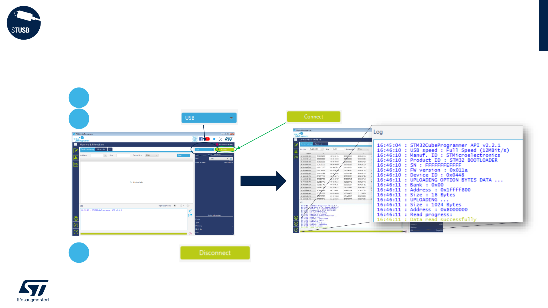
Launch STM32CubeProgrammer program with dongle connected to PC
Take care to select then click
If OK then click on and close the program
Quick Start
Pre-requisite (5/5)
9
8
9
7
Page 10

STUSB4761 customization
using the GUI and the Dongle
Export STUSB4761 configuration file from the GUI
Plug the board in DFU mode
Load STUSB4761 NVM configuration file into the dongle
Switch the board into PASTE mode
Store new NVM content into STUSB4761
11
12
13
14
15
Page 11

The GUI (STSW-STUSB005) is typically used to customize STUSB4761 parameters in
order to meet application requirements (see STSW-STUSB005 QUICK START Guide).
Once a configuration is frozen, it must be first saved in the STSW-STUSB011 working
directory (cf p.5)) by pressing the ‘EXPORT BIN file’ button:
Save as « NVM_Config.bin »
in the STSW-STUSB011 working directory
STUSB4761 customization (1/5)
Export STUSB4761 configuration file from the GUI
11
1
2
2
Page 12

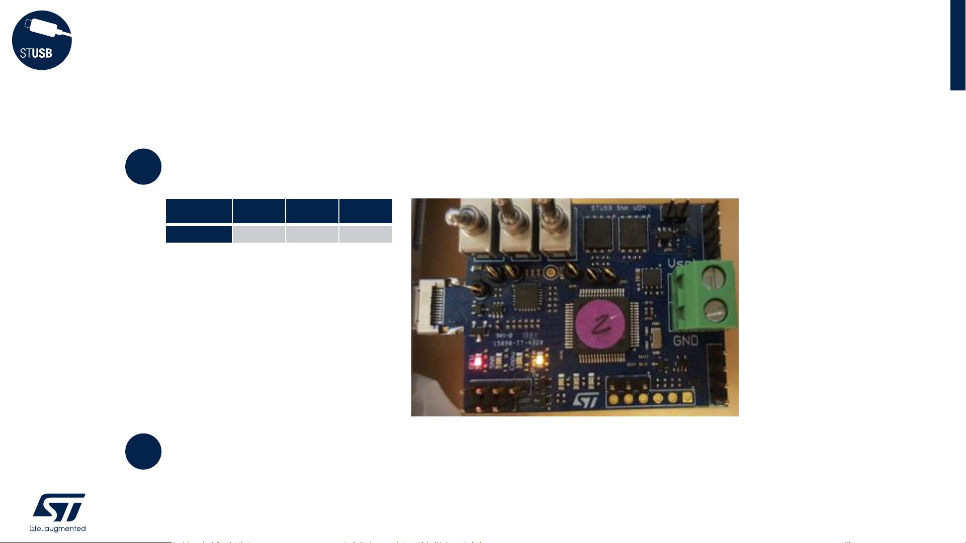
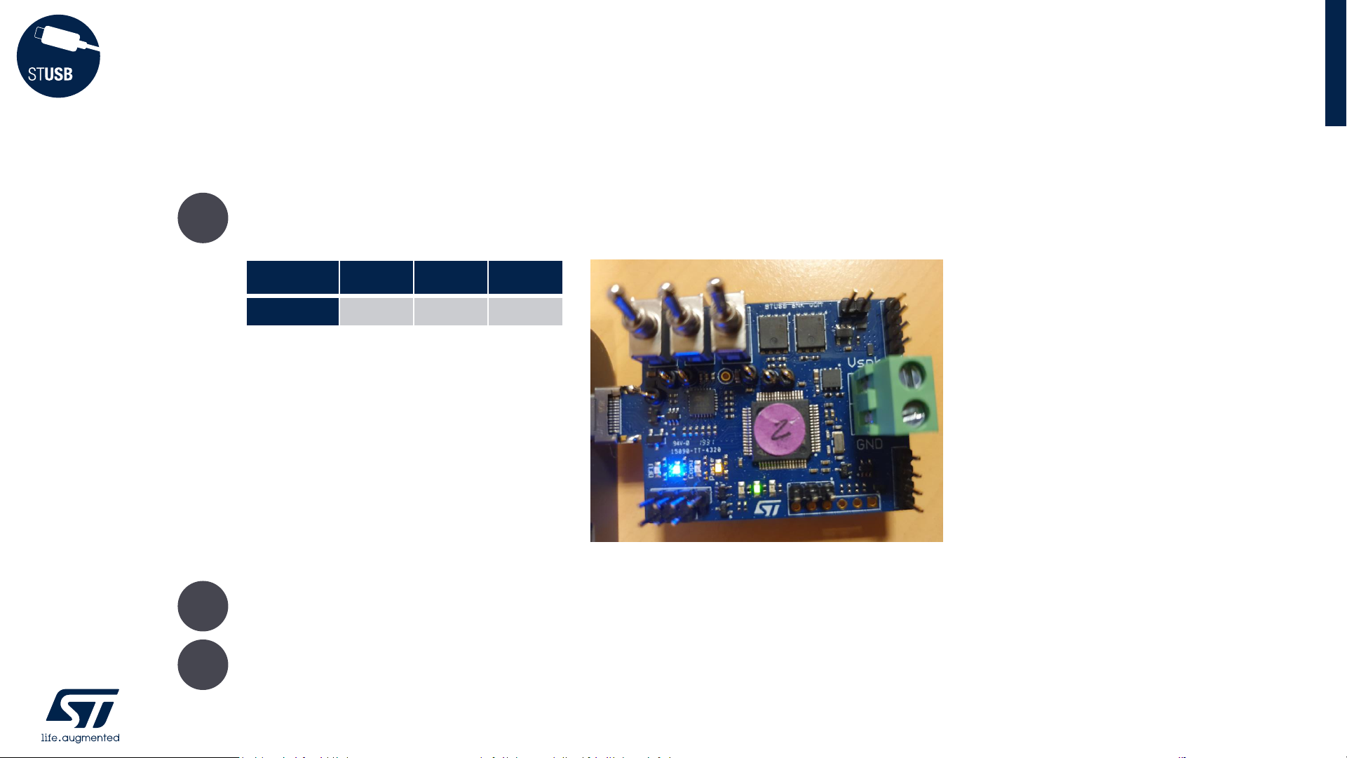
Plug EVAL-SCS003V1 board into USB-C port of the PC with below switch configuration:
Check that Red and Orange LEDs are continuously ON
STUSB4761 customization (2/5)
Plug the board in DFU mode
12
mode
SW0 SW1 SW2
DFU
ON
off off
4
3
Page 13

From STSW-STUSB011 working directory, launch ‘Flash_Config.bat’
STUSB4761 customization (3/5)
Load STUSB4761 NVM configuration file into the dongle
13
NB: ‘Flash_Config.bat’ uses
‘NVM_Config.bin’ as NVM file.
In case the NVM file is exported with
another name, just edit ‘Flash_Config.bat’
6
Check that file download is successful:
5
Page 14

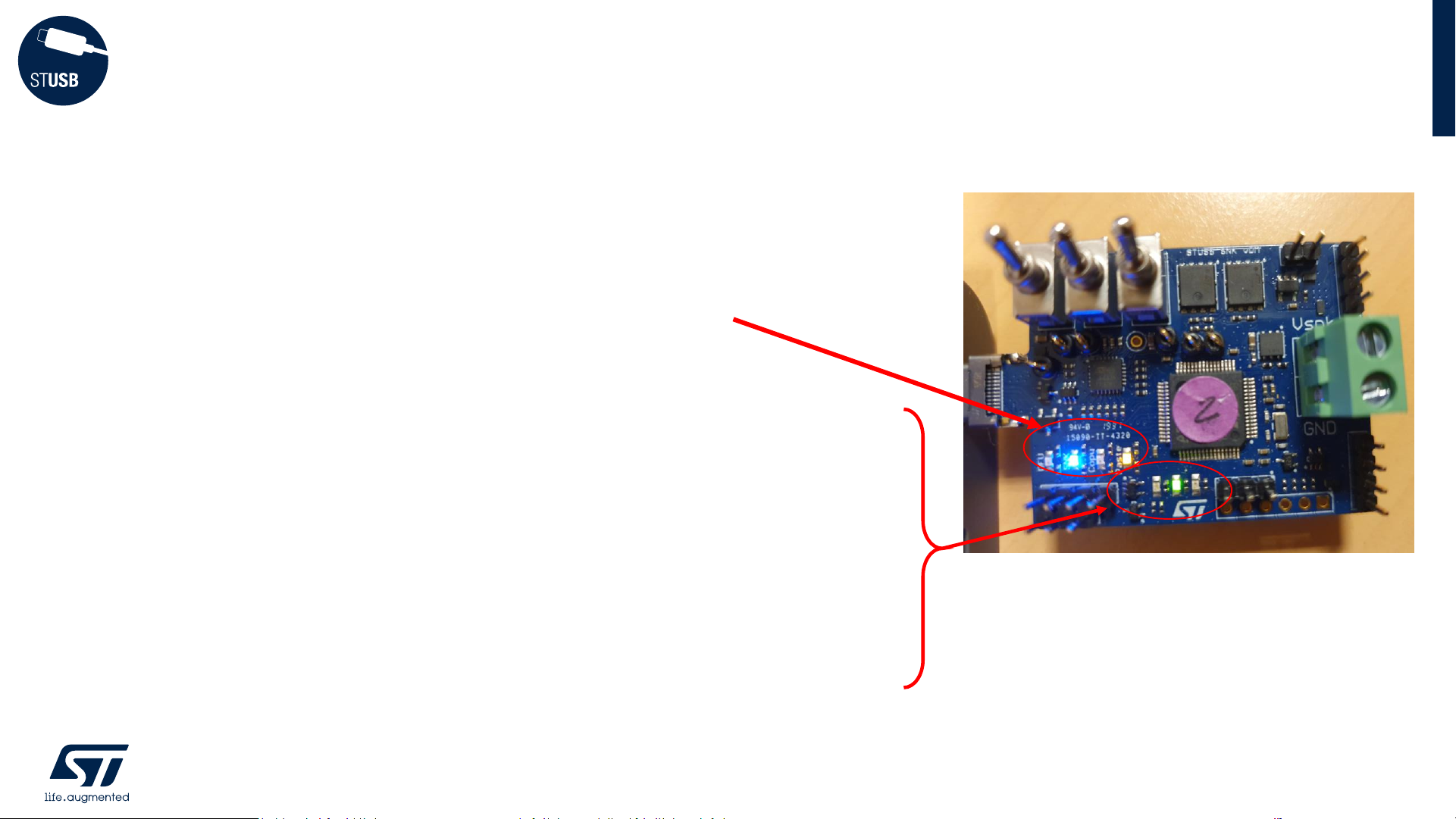
Toggle dongle switches like below picture:
Ensure that Orange LED is continuously ON
STUSB4761 customization (4/5)
Switch the board into PASTE mode
14
8
mode
SW0 SW1 SW2
PASTE
off
ON
off
7
Page 15

Plug the dongle into a powered STUSB4761 application board (to be customized):
Blue and Green status LEDs should be lighting continuously when all is OK. Dongle
can be unplugged
Unpower STUSB4761:
new NVM content is taken into account ONLY at STUSB4761 power-up.
STUSB4761 customization (5/5)
Store new NVM content into STUSB4761
15
application board
9
10
11
Page 16

Reading STUSB4761 NVM content
using the dongle and the GUI
17
18
19
20
select COPY mode
copy STUSB4761 NVM content into the dongle
plug the board in DFU mode
import STUSB4761 configuration file from the dongle
Page 17

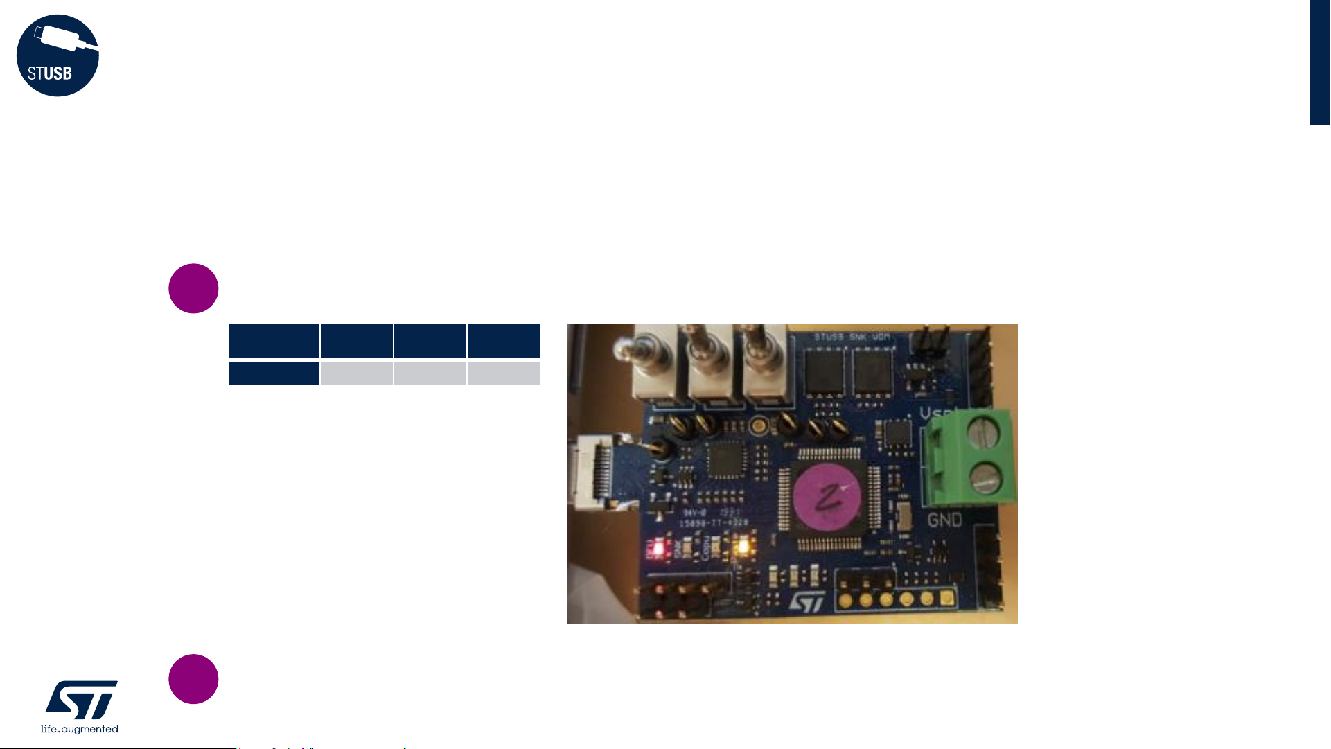
• Toggle dongle switches like below picture
• Connect EVAL-SCS003V1 dongle to PC and
ensure that Green LED is continuously ON
Reading STUSB4761 NVM (1/4)
select COPY mode
17
1
2
mode
SW0 SW1 SW2
COPY
off
ON ON
Page 18

Plug EVAL-SCS003V1 dongle into STUSB4761 application board (or EVLSTCH03-45WPD)
blue and green status LEDs should be lighting continuously when all is OK.
STUSB4761 NVM content is now stored into dongle flash memory:
1. It can be used as a reference for other application boards: user can proceed to duplication
using the ‘PASTE’ mode (see to )
2. It can be imported into the GUI for further analysis. Move to
Reading STUSB4761 NVM (2/4)
copy STUSB4761 NVM content into the dongle
18
application board
4
3
5
6
7
11
Page 19
Plug EVAL-SCS003V1 board into USB-C port of the PC with below switch configuration:
Check that Red and Orange LEDs are continuously ON
Reading STUSB4761 NVM (3/4)
plug the board in DFU mode
19
mode
SW0 SW1 SW2
DFU
ON
off off
7
6
Page 20
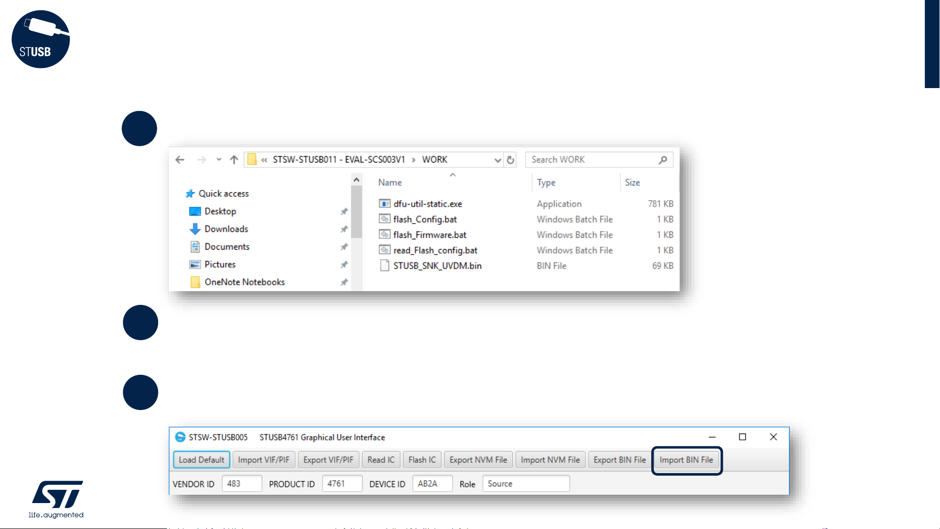
From the working directory, launch ‘read_Flash_config.bat’
Reading STUSB4761 NVM (4/4)
import STUSB4761 configuration file from the dongle
20
8
9
The NVM content is automatically stored in ‘NVM_Config_read.bin’ file.
NB: if file already exists, please remove or save under different name as the
‘read_Flash_config.bat’ is not able to override existing ‘NVM_Config_read.bin’ files
Open the STSW-STUSB005 GUI and import ‘NVM_Config_read.bin’ file pressing
the « IMPORT BIN FILE » button
10
Page 21

Connecting to a SOURCE
using SINK Mode
use the dongle as a Sink
sink connection status
22
23
Page 22
Toggle dongle switches like below picture
Then plug to a SOURCE
With default firmware, the dongle will automatically try to negociate 9V/1.5A first
or by default 5V/1.5A
Connecting to a SOURCE (1/2)
use the dongle as a Sink
22
mode
SW0 SW1 SW2
SINK
off off off
1
2
3
Page 23
• Blue and Orange LEDs are statically lighting
• When PD contract is established, Green LED is ON static
• Red LED blinks regularly 1 time to indicate CC1
connection or 2 times to indicate CC2 connection
• Blue LED is blinking regularly 2 times to indicate that
dongle is Sink
Connecting to a SOURCE (2/2)
sink connection status
23
Page 24

Updating EVAL-SCS003V1 dongle firmware
using ‘DFU’ mode
25
26
plug the board in DFU mode
load the new firmware into the dongle
Page 25
Plug EVAL-SCS003V1 board into USB-C port of the PC with below switch configuration:
Check that Red and Orange LEDs are continuously ON
Updating dongle firmware (1/2)
plug the board in DFU mode
25
mode
SW0 SW1 SW2
DFU
ON
off off
2
1
Upon ST request, EVAL-SCS003V1 dongle firmware can be updated.
Please follow bellow process:
Page 26

From the STSW-STUSB011 working directory, launch ‘Flash_Firmware.bat’
with the new STUSB_SNK_UVDM.bin provided by ST
Updating dongle firmware (2/2)
load the new firmware into the dongle
26
4
Check dongle firmware has been properly updated:
3
Page 27

TRICKS
Page 28

Known Error
28
• Fresh dongles might have difficulties to power up with some PC or laptop
• Work around is to use Legacy-to-C female adaptor to connect dongle to
PC
• Adaptor example:
Page 29

© STMicroelectronics - All rights reserved.
The STMicroelectronics corporate logo is a registered trademark of the STMicroelectronics
group of companies. All other names are the property of their respective owners.
Thank you
© STMicroelectronics - All rights reserved.
The STMicroelectronics corporate logo is a registered trademark of the STMicroelectronics
group of companies. All other names are the property of their respective owners.
Thank you
For More Information
search EVAL-SCS003V1 on www.st.com
 Loading...